TORNOS AS 14 - SAS 16 - BS 20
|
|
|
- Maximillian Warner
- 6 years ago
- Views:
Transcription

 4 50 03 17 52 Fax: 00 33 (0) 4")

1 SELLING / BUYING NEW AND USED MACHINE TOOLS REBUILDING OF MACHINE TOOLS PAE du Pays Rochois - BP , Rue de l'industrie - ETEAUX LA ROCHE SUR FORON France Tel: (0) Fax: (0) Used and New Spare Parts and Attachments TORNOS AS 14 - SAS 16 - BS 20 Rebuilt TORNOS AS14


2 RECONSTRUCTION TORNOS AS14, SAS16 and SAS16DC Variation cam Spindle Thread milling CNC Slide CNC Pickup CNC NEW CROSSED SLIDES 2 AXIS CNC IN STATION 4 Technical characteristics in station 4 Standard stroke axis X 25 mm Max linear speed axis X 10 m/mn Standard stroke axis Z 50 mm Max linear speed axis Z 15 m/mn Strenght of push on the axis 2000 N Resolution 1 µ Ball screw with preforced nut Guiding on preforced ball rails Complete centralized greasing Using standards tool holders - Minimum dimensions - Visual access operator SAMO SAS Pae du Pays Rochois 400, rue de l industrie ETEAUX Tél Fax Web : samo@samo.fr 2
3 Request Quotation for TORNOS Spare Parts Please fill in this form in capital letters Company name: Country: Name: Phone number: Fax number: adress: Please send me prices and delays for: # REF Designation Qty Page Please send us your request by fax By samo@samo.fr

4 TORNOS AS14 / SAS 16 SPARE PARTS Pages Main Spindle group 4 Pulley shaft spindles rotation group 7 Central Block group 6 Camshaft group 7 Pickup group 8 Tightening group 11 Thread milling attachment group 12 Independants group 13 Drum group 15 Reel or Drum + support group 16 Slides group 17 Bolting and indexing group 20 Rod control front slides stations Oscillating bar stop group 23 Loading group 24 Speed box production group 26 Spindle speed box group 29 Upper camshaft group 30 Equippments and attachments group 32 For infos about prices and delays: or samo@samo.fr 3


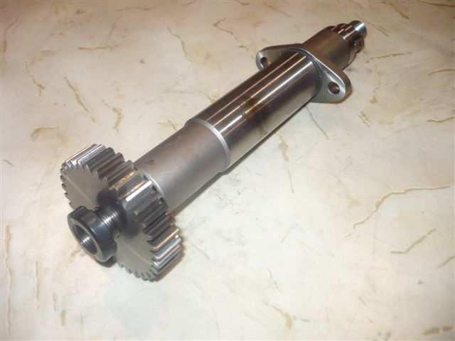
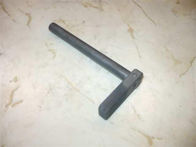
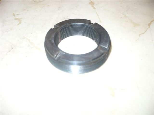
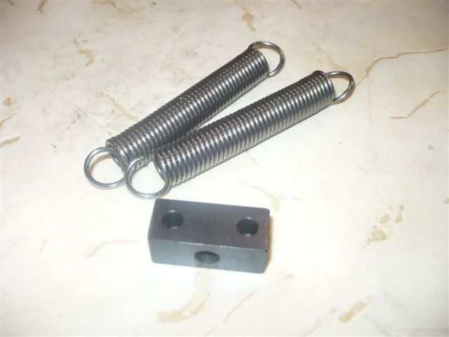
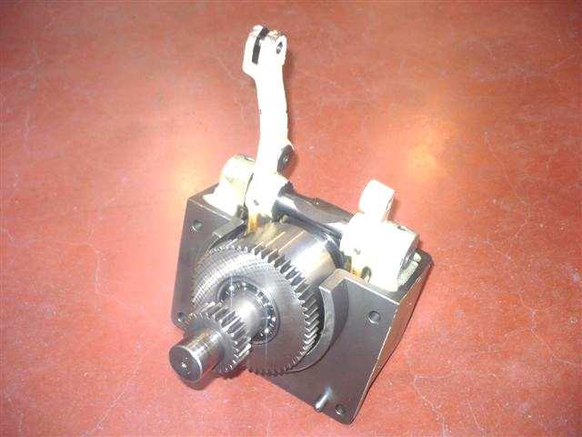
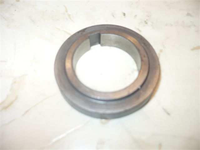
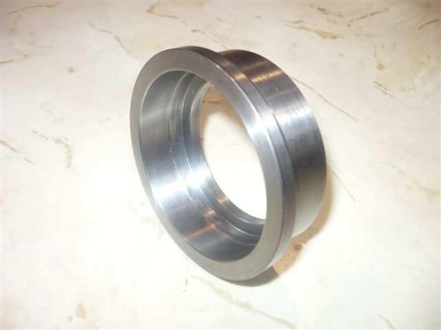
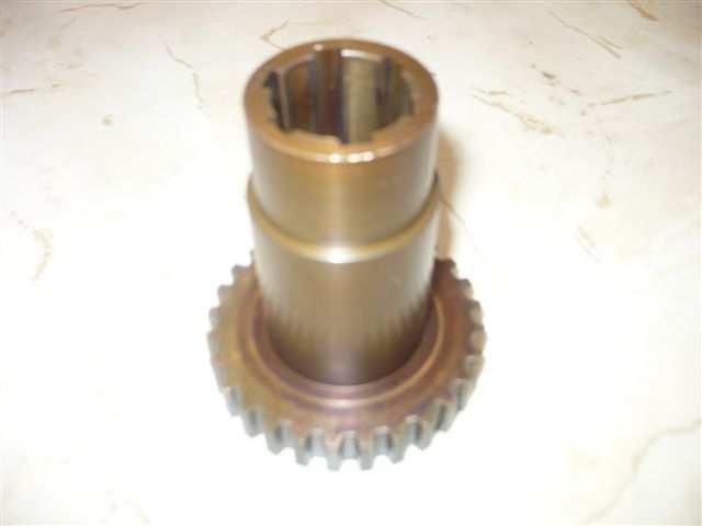
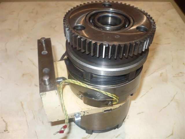
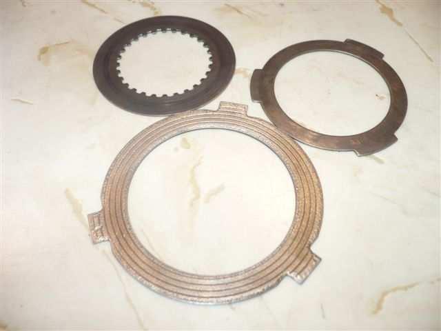
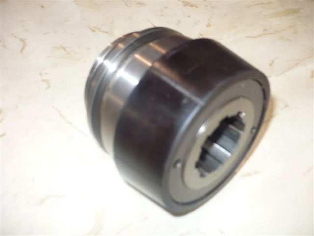
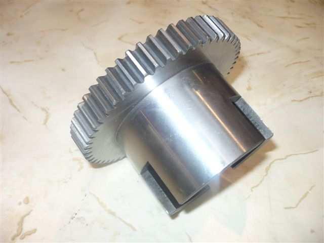
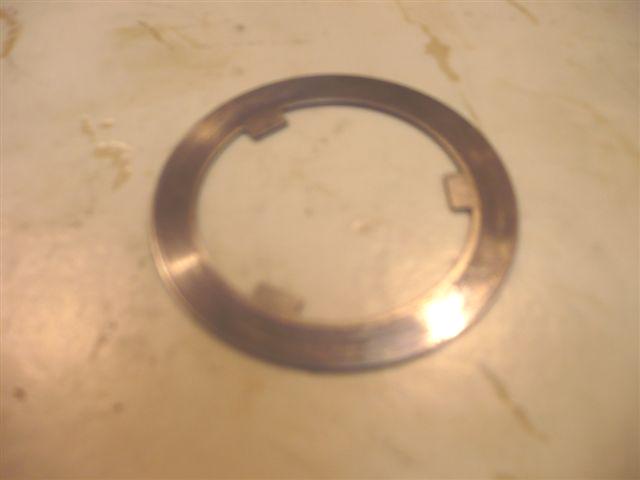
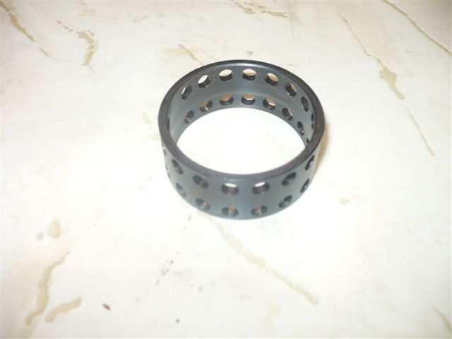
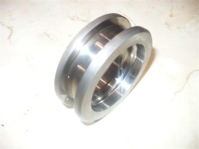
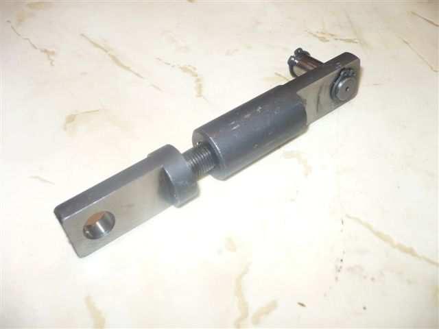
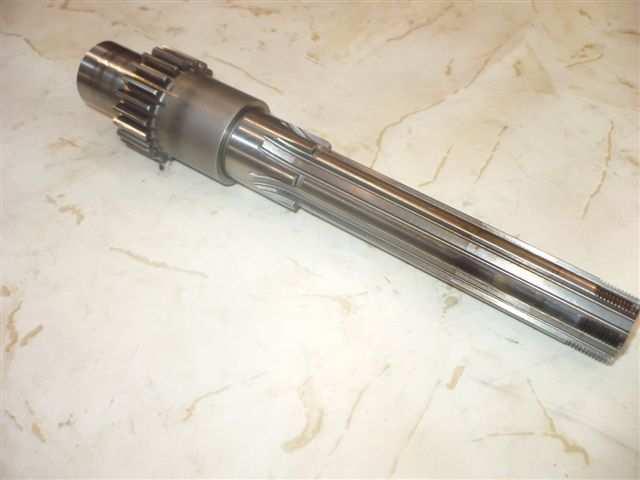
5 Main spindle group Spindle group Stop ring toggle holder Tightening sleeve Tightening toggle AS AS AS12149 Central gear Fixation nut Bearing Spindle gear AS Collet tightening sleeve holder Pin hard metal Toggle Shear connector Spring pivot AS AS12881 AS Toggle holder Tightening tube Used serviced Spindle AS Bearing tie AS


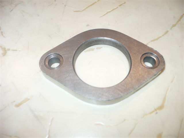
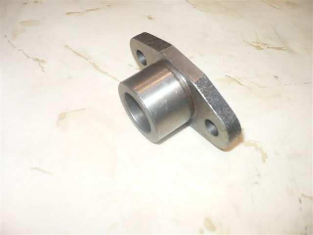
6 Main spindle group Spindle group Feed tube Ring Spindle nose Spindle nose AS Tightening sleeve Toggles holder 381 SAS SAS16 SAS16 Spindle gear Baffle 382 SAS16DC SAS16 Spindle nose SAS16.6 For infos about prices and delays: or samo@samo.fr 5


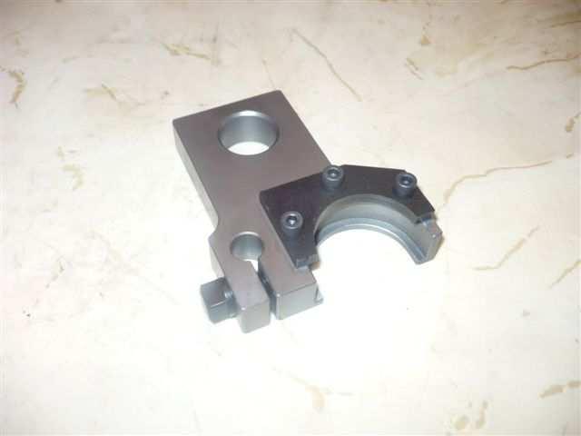
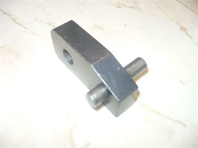
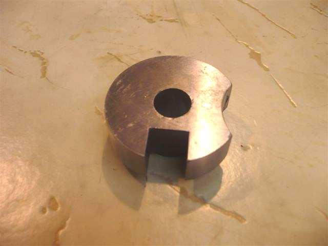
7 Central Block group Centring Pin Sprocket Pads 2 flats 35x20x Pin 53x12x22 Pin 72x14 Feeding pad AS Stop rod Sprocket 24x12x12 Guiding perch AS Central slide Central Block feed pin 150x AS If your spare part is not in this catalog, Please contact us: samo@samo.fr 6


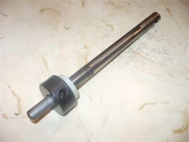
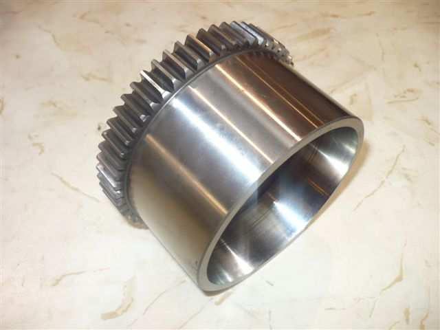
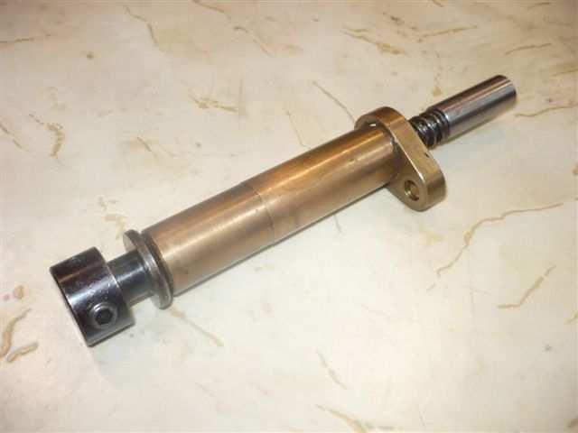
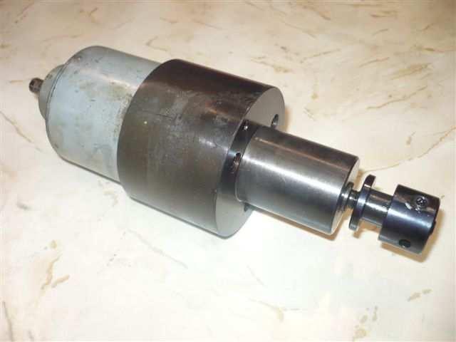
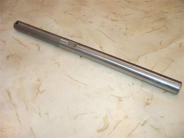
8 Central shaft group Straight wood key 54x8x7 Ring 35x45x40,5 Bush 138x41x Bush 61x41x35 Gear Z 37 Gear Z 42 AS Gear Z 42 Gear Z 37 Central shaft Pulley shaft spindles rotation group Pulley Pulley shaft Gear AS Pulley hub


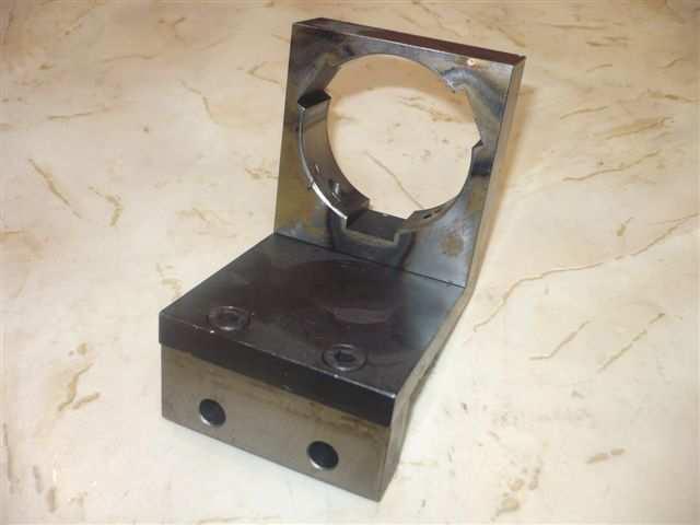
9 Pickup group Sub Spindle - Pickup group Pin 136x20 Nut 6p M16x10 Stop quill alone AS AS28/26 Fork for QUILL Feed support of subspindle Tightening coil AS AS AS24207 Bronze box Diam 38x32xLg45 Sub Spindle Steady front support AS AS AS2448 Long clamping bush Toggle holder Piston AS Compression spring Ø3,8x25 Toggle holder ring 41x39x11,5 Clamping bush collet holder


10 Pickup group Sub-Spindle - Pickup group Tightening cast iron + screw Tightening Toggles Pin hard metal Diam 24x4 AS AS AS24259 Sub Spindle cap M32x1 Against operation stop screw Roller 20x10x AS AS14269 Tightening cast iron Pin on rod Non-stop Sub Spindle feed lever AS28-7 Special stop Cast iron sub-spindle tightening Feed lever pickup AS AS2420 Feed lever sub-spindle Extraction rod Non stop tightening sub-spindle lever AS AS2410 9


11 Pickup group Sub-Spindle - Pickup group Adjustment tightening screw Flask Rlts Ejection lever AS AS AS groupe avance contre Spindle - Pickup Feed slide Feed pad L39 Pin 65x12x Roller 26x12x12 Outlying socket 19,50x13x7 Roller 24x12x Pin 68x12x22 Safety pin Socket 17x12x AS AS Knurled Pin 170x20 Feed slide Pad AS


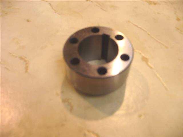
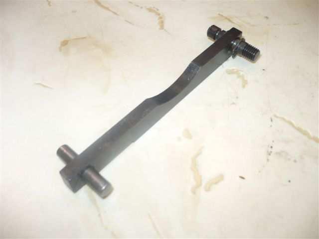
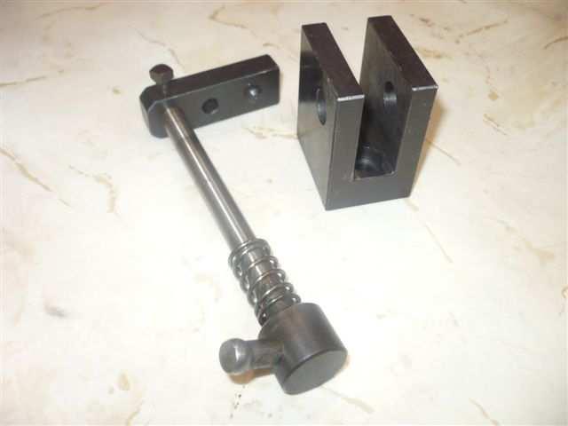
12 Tightening group Manual and automatic tightening lever Outlying Pin 51x12x26 Roller 26,50x17x15 Pin 50x12x AS AS11415 Pin 37x10x17,80 Roller 20x12x10 Roller 24x12x12 AS AS1365 Pin 118x22 Pin 46x12x20 Pin 53x12x22 AS AS Automatic tightening lever Automatic tightening lever L02 Tightening Roller 26,5x15x SAS16 SAS SAS16 Needles SAS16 11

13 Thread milling attachment group Used spare parts 12


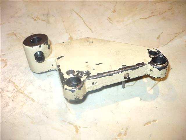
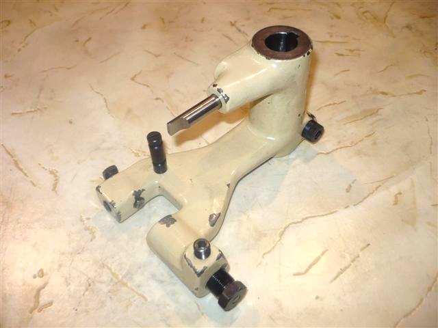
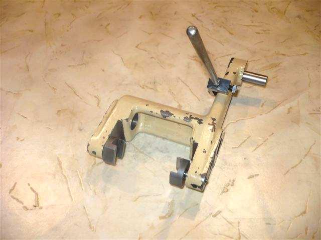
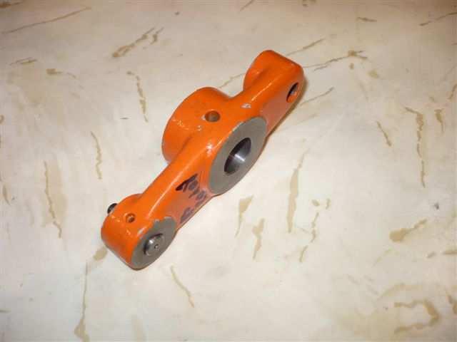
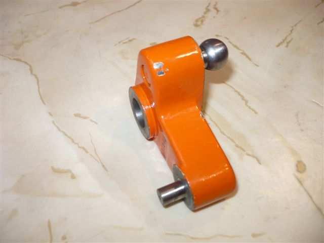
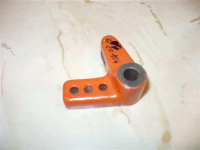
14 Thread milling attachment group Second hand spare parts Independants group Independant lower lever group, large lever Cast Iron lever L 337 Independant lower lever L337 Lower slide L Roller 24x12x12 Pin 50x12x19,70 Pad L AS Nut M20/125 Pin Cylindrical head 90x20x35 Traction spring L


15 Independants group Independant lower lever group, small lever Cast Iron Lever L225 Independant lower lever Pad L Nut M20/125 Pin 50x12x19,70 Roller 24x12x AS AS1365 Traction spring Pin cylindrical head 90x20x35 Upper slide L x If your spare part is not in this catalog, Please contact us: samo@samo.fr 14


16 Drum group Drum group Pole drum support box Ring Ball pin AS Support Ring Thickness hold Drum stop screw AS12299A Joint SKEGA Crown Gear AS10647 For infos about prices and delays: or samo@samo.fr 15


17 Reel or Drum + support group Reel or Drum + support group Drum fixation Drum foot Roller 45x22x20 Roller 36x14x20 AS Drum foot pin Drum location finger Fixation Bolting Finger AS7561 AS Bolt Connection pin Drum guide AS AS1567 Cast Iron drum support Bolting Plate AS1514 SAS16 AS SAS16 For infos about prices and delays: or samo@samo.fr 16


18 Slides group Slides 2 and 3 group Plate Split tube Scew head H Washer Ø AS AS14253 AS1431-1/ / AS14357 Jib Adjusting screw Pusher 140x12,16x17 Short Rack AS AS14153 Spring 220x17,40 Vernier Straight teeth wheel Z AS AS14247 Slide flap Slide stop station 2 and 3 Toolholder AS14321 AS30/80 If your spare part is not in this catalog, Please contact us: samo@samo.fr 17


19 Slides group Slides 1 and 4 group Screw head H Washer Jib Adjusting screw Pusher 115x10,20x15 AS1431-1/ / AS AS Vernier Spring 215x13,60 Long Rack AS RCM Straight teeth wheel Z35 Stop slide station 4 Toolholder AS14249 AS30/80 Cast Iron rod station 4 Lever station 4 Feed slide Box 55x40 AS1450 AS If your spare part is not in this catalog, Please contact us: samo@samo.fr 18


20 Slides group Slides 5 and 6 group Adjusting screw Nut Pusher 135x10x13 AS AS AS14285 Ball pin Cap spring 215x13, AS RCM518 Roller 20x10x12 Pivot Pin slide 5 and AS14269 AS For infos about prices and delays: or samo@samo.fr 19


21 Bolting and Indexing group Bolting and Indexing group Pin Indexable gear CROWN GEAR 70M AS125-2 Pin 27x10 Pin Roller Roller bolt Knurled Pin 410x28 Spring 120x29, AS Maltese cross Screw finger If your spare part is not in this catalog, Please contact us: samo@samo.fr 20


22 Rod control front slides stations Rod control stations 2 et 3 Feeds Pin 330x28x38 Front box 80x40x74 Box 95x40 AS AS14163 AS Pin station 1 and 4 265x28 Pin 27x10 Roller 20x10x AS14269 Lower Pin rod 52x12 Box 16x12 Pin 34x AS AS AS For infos about prices and delays: or samo@samo.fr 21


23 Rod control front slide station Rod control stations 1 and 4 Front box 86x40x74 Feeds Pin 317x28x38 Box 55x40 AS AS AS Upper Pin station 3 and 4 255x28 Pin 27x10 Roller 20x10x AS AS AS14269 Lower Pin rod 52x12 Box 16x12 Pin 34x AS AS AS For infos about prices and delays: or samo@samo.fr 22


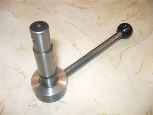
24 Oscillating bar stop group Oscillating bar stop group Pin 28x10 Pin 27x10 Oscillating stop gear 19 teeth AS AS AS Key 120x8x7 Pin Compression spring 27x15, AS AS RPC245 Roller 20x10x12 Bit holder lever Screw knurled head AS Bar stop lever Stop holder Pin 875x26 Cracked screw AS AS29089 Oscillating stop Pin 150 x 20 Roller holder Cast iron stop bar lever AS AS AS


25 Loading group Loading group return feed Bar return and feed pads Stop Pin 130x15 M10 Rod AS Wheel 24x12x12 Bar feed adjustment lever Bar return lever AS1365 AS1158 AS1194 Feed bar Feed lever Feed tube Loading bar AS Pin 53x12x22 Traction spring 80x20 Traction spring 335x AS Nut Rod clip Pin 36,10x10x18 Pin AS


26 Loading group Loading group Bar ending pin 80x12x21,70 Lever rein Pin 120x AS11315 AS11265 AS11205 Wheel 20x10x12 Contact stop Rod clip Pin 26,5x10x AS AS11231 Feed lever Loading lever Feed bar lever SAS SAS SAS16 Feed lever Feed lever SAS16 L. patin 120 SAS16 For infos about prices and delays: or samo@samo.fr 25
27 Speed box production group 26
28 Speed box production group 27


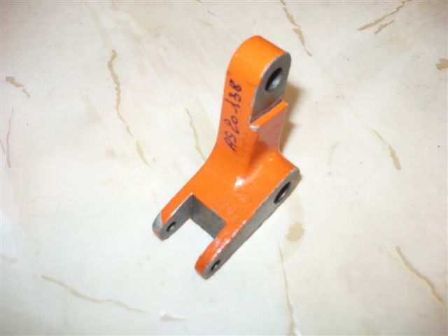
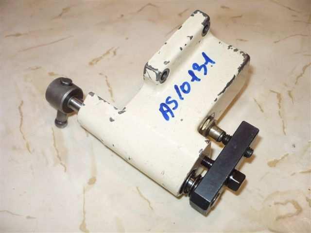
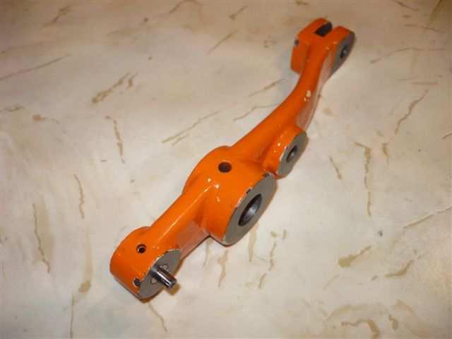
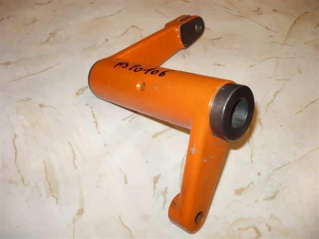
29 Speed box production group Expansion rdl AS Cast iron acceleration AS20106 Cast iron acceleration Control release Speed box safety AS2060 AS10131 Control lever of release Control lever of release Speed box control lever AS20154 AS


30 Speed box production gear Trigger mecanism Control lever AS Spindle speed box group Clutch Endless screw wheel For infos about prices and delays: or 29


31 Upper Camshaft group Camshaft group Extraction cam ejector beak Cam holder sleeve 2 and 3 Sleeve nut Cam follow up slide station 6 Cam follow up slide station 4 Cam follow up slide station Box Back Box Cam follow up slide station AS Box 60x50x70 Splite nut M30x125 Box 50x62x AS Bronze wheel Camshaft Endless screw AS AS


32 Upper Camshaft group Camshaft group Cam holder sleeve 1 and 4 AS14123 Upper Camshaft group Ejector group Compression spring 120x9 Pin 140x18x30 Pad RCC113 AS AS2433 Reel of extraction Pin 36x10 Control lever in cast iron AS2431 AS Bonze wheel 9499 SAS16 31


33 ATTACHMENTS Steady W12 Sliding Tail Stock station 1 to 5 Broaching tool holder AS AS27/3-5A AS32/ Tool holder Double driller Milling attachment AS37/32 AS27/3D AS25/8 Re-engaging device Broaching attachment Broaching Toolholders AS27/15 AS31/ AS32/5 Independant Non-revolving Spindle strengthened Independant non-revolving spindle Toolholders tangential station 1 to 5 AS 27/ AS 27/8-1 station 3 à 6 AS30/10 Double driller ES16 Independante revolving Spindle on slide Slider AS27/13 Station AS27/82 AS32/3A 32


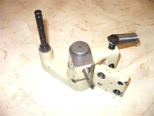
34 Polygon-Generating and Thread-Milling Attachment 2 Speeds Attachment to mill flats and thread Stations 2 and 3 (Other stations upon request) 33


 4")
 4 50 03 35 36 Visit")
35 SAMO P.A.E. du Pays Rochois - B.P , Rue de l'industrie ETEAUX LA ROCHE SUR FORON Cedex France TEL: (0) FAX: (0) Visit our website:
12. Mechanical Drawings & Parts Breakdown List
 12. Mechanical Drawings & Parts Breakdown List Note: When ordering parts, please be prepared with, 1. Machine model & serial number. 2. Item number. 3. Part number and description. 4. Year of Production.
 488 PARTS LIST 1 3 SCREWS FOR NO. 2 2 FLYWHEEL CAP 3 FLYWHEEL 4 END NUT FOR NO. 10 5 BALL BEARING FOR NO. 3 (1 st ) 6 BALLBEARING FOR NO. 3 (2nd) 7A CLUTCH RACE KEY 7B CLUTCH RACE 7C CLUTCH SPRING 7D 7
RYOBI 10 IN (254 MM) TABLE SAW MODEL NO. BT REPAIR SHEET
 TABLE SAW MODEL NO. BT REPAIR SHEET") RYOBI 0 IN (2 MM) TABLE SAW MODEL NO. BT00- REPAIR SHEET 2 RYOBI 0 in. (2 mm) TABLE SAW - MODEL NO. BT00- FOR MITER TABLE ASSEMBLY, REFER TO FIGURE B FOR BLADE GUARD ASSEMBLY, REFER TO FIGURE E FOR RIP
RYOBI 0 IN (2 MM) TABLE SAW MODEL NO. BT00- REPAIR SHEET 2 RYOBI 0 in. (2 mm) TABLE SAW - MODEL NO. BT00- FOR MITER TABLE ASSEMBLY, REFER TO FIGURE B FOR BLADE GUARD ASSEMBLY, REFER TO FIGURE E FOR RIP
Operating Instructions and Parts Manual Electronic Variable Speed Turret Mill Model JTM-1050EVS
 Operating Instructions and Parts Manual Electronic Variable Speed Turret Mill Model JTM-1050EVS JET 427 New Sanford Road LaVergne, Tennessee 37086 Part No. M-690060 Ph.: 800-274-6848 Revision G1 06/2015
SECTION 9: PARTS. Table Breakdown REF PART # DESCRIPTION REF PART # DESCRIPTION
 SECTION 9: PARTS Table Breakdown 1 2 3 4 5 6 7 8 9 10 11 12 13 14 15 16 17 18 19 20 21 22 23 24 23 25 17 26 27 8 1 P0675001 CAP SCREW M8-1.25 X 30 15 P0675015 SUPPORT BLOCK 2 P0675002 TABLE SUPPORT BLOCK
RYOBI 10 in. (254 mm) TABLE SAW MODEL NO. BT3100 REPAIR SHEET
 TABLE SAW MODEL NO. BT3100 REPAIR SHEET") RYOBI 0 in. (4 mm) TABLE SAW MODEL NO. BT00 REPAIR SHEET FOR MITER TABLE ASSEMBLY, REFER TO FIGURE B FOR BLADE GUARD ASSEMBLY, REFER TO FIGURE E FOR RIP FENCE ASSEMBLY, REFER TO FIGURE C FOR MOTOR ASSEMBLY,
RYOBI 0 in. (4 mm) TABLE SAW MODEL NO. BT00 REPAIR SHEET FOR MITER TABLE ASSEMBLY, REFER TO FIGURE B FOR BLADE GUARD ASSEMBLY, REFER TO FIGURE E FOR RIP FENCE ASSEMBLY, REFER TO FIGURE C FOR MOTOR ASSEMBLY,
Operating Instructions and Parts Manual 5-ft. Radial Arm Drill Press Models J-1600R, J-1600R-4
 Operating Instructions and Parts Manual 5-ft. Radial Arm Drill Press Models J-1600R, J-1600R-4 JET 427 New Sanford Road LaVergne, Tennessee 37086 Part No. M-320038 Ph.: 800-274-6848 Revision H 01/2016
 2705 03-09 99 98 97 82 88 89 83 84 85 86 87 101 103 100 106 81 71 105 104 73 74 75 76 77 78 80 79 57 62 58 56 63 65 66 67 68 64 69 70 59 60 61 31 30 29 32 34 35 41 40 42 36 37 38 39 43 4445 46 33 55 54
PARTS LIST: Air Control Assembly (1632 Sander)
") PARTS LIST: Air Control Assembly (1632 Sander) 1 6293482 Filter... 1 2 6293483 Solenoid Valve... 1 3 6293484 Brake Cylinder... 1 4 6293485 Multi-Hole Connector... 1 5 6293486 Air Valve... 1 6 6293487 Air
PARTS LIST: Air Control Assembly (1632 Sander) 1 6293482 Filter... 1 2 6293483 Solenoid Valve... 1 3 6293484 Brake Cylinder... 1 4 6293485 Multi-Hole Connector... 1 5 6293486 Air Valve... 1 6 6293487 Air
11. PARTS LIST 11.1 HEAD STOCK UPSIDE (1) 11-1
 11-1") 11. PARTS LIST 11.1 HEAD STOCK UPSIDE (1) 11-1 HEAD STOCK UPSIDE (1) PARTS LIST NO. PART NO DESCRIPTION QTY 1. SC-M6x20L SOCKET CAP SCREW 4 2. K6-K042-00 TOP BEARING CAP 1 3. 6009LLB BALL BEARING 1 4.
11. PARTS LIST 11.1 HEAD STOCK UPSIDE (1) 11-1 HEAD STOCK UPSIDE (1) PARTS LIST NO. PART NO DESCRIPTION QTY 1. SC-M6x20L SOCKET CAP SCREW 4 2. K6-K042-00 TOP BEARING CAP 1 3. 6009LLB BALL BEARING 1 4.
Headstock Gear System
 Headstock Gear System (0000 Series Parts) 10 7 6 5 4 3, 2 16 11 12 13 14 15 9,8 1 90 17 18 19 20 21 22 23 24 25 26 27 28 29 30 31 32 33 34 91 93 94 95 96 97 98 99 100 102 104 106 108 109 92 101 103 105
Bell and Howell Spare Parts from MTS
 Telephone: 01708 377444 Part No. Description Location in B&H Manual BH053014 Envelope opener valve Fig 12-41 BH053025 Roller assy cam follower Fig 2-38 & 3-67 & 8-43, 62 & 12-28 BH053210 Table lock handle
25-200H. 12 Planer / Jointer. with Helical Cutterhead. Parts List.
 25-200H 12 Planer / Jointer with Helical Cutterhead 4001824 Parts List www.rikontools.com CABINET ASSEMBLY PARTS EXPLOSION & PARTS LIST KEY NO. DESCRIPTION KEY NO. DESCRIPTION 1 Pan Head Screw M6x12 P25-200H-1
RYOBI 10 in. TABLE SAW - MODEL NO. BT3000
 FOR MITER TABLE ASSEMBLY, REFER TO FIGURE 0 RYOBI 0 in. TABLE SAW - MODEL NO. BT000 FIGURE 5: 0 in. TABLE SAW FOR BLADE GUARD ASSEMBLY, REFER TO FIGURE FOR RIP FENCE ASSEMBLY, REFER TO FIGURE FOR MOTOR
EXPLODED PARTS LIST VSS 60
 Page(s): / ENGINE Page(s): / No Code Name Qty No Code Name Qty 05083 Handle assembly 05076 Connecting rod 3 Box Hex locking nut M8 7 5 Washer 8xx 6 Hex locking nut M6 7 T bolot M8x 8 Pin with hole 9 0506
INSTRUCTIONS AND PARTS LIST POWER HAMMER
 INSTRUCTIONS AND PARTS LIST POWER HAMMER DAKE (Division of JSJ) 724 Robbins Road Grand Haven, Michigan 49417 616.842.7110 Phone 800-937-3253 616.842.0859 Fax 800-846-3253 Web: www.dakecorp.com E-mail :
MODEL D DIESEL PILE HAMMER
 AMERICAN PILEDRIVING EQUIPMENT, INC. MODEL D125-42 DIESEL PILE HAMMER SPARE PARTS BOOK Corporate Office 7032 S. 196th Street Kent, WA, USA 98032 Tel: 1-800-248-8498 Tel: 1-253-872-0141 Fax: 1-253-872-8710
HEADSTOCK (CASTNG & CONTROLS)
") HEADSTOCK (CASTNG & CONTROLS) REF.NO. PART NO. DESCRIPTION Q'TY 1 VE2101 HEADSTOCK CASTING 1 2 VE2134 HEADSTOCK COVER 1 3 VE2116 SHAFT 1 4 VE2117 GEAR 1 5 VE2118 WASHER 1 6 VE2119 SHAFT 1 7 VE2120 GEAR
HEADSTOCK (CASTNG & CONTROLS) REF.NO. PART NO. DESCRIPTION Q'TY 1 VE2101 HEADSTOCK CASTING 1 2 VE2134 HEADSTOCK COVER 1 3 VE2116 SHAFT 1 4 VE2117 GEAR 1 5 VE2118 WASHER 1 6 VE2119 SHAFT 1 7 VE2120 GEAR
How to program the digital speed display (This is factory set and will only need to be programmed if the unit is replaced)
") How to program the digital speed display (This is factory set and will only need to be programmed if the unit is replaced) 1. Press and hold the set button (top left corner) until the display shows Fun
How to program the digital speed display (This is factory set and will only need to be programmed if the unit is replaced) 1. Press and hold the set button (top left corner) until the display shows Fun
Parts List: VBS-3612 Band Saw
 Parts List: VBS-3612 Band Saw (refer to breakdowns on pages 35 and 36) Index No. Part No. Description Size Qty 1... VBS3612-101...Gear Box... 1 2... TS-0209101...Socket Head Cap Screw...3/8-16 x 2-1/4...
Section J DISTRIBUTOR
 Section J DISTRIBUTOR 1J 1. 47-094344-003 Front Pulley Shaft 2. 47-091905-003 Turn Plate (right-hand) 3. 11-051038-001 Hex Hd. Cap Screw (8 mm x 16 mm) 4. N.A. Distributor Frame Complete 5. 47-090547-004
Number Wheeler P/N Description Set Rex P/N Notes Base 1 J Support, Right 1 J Support, Left 1 J Nut (M8)
") 1 603500 Base 1 J001 2 603501 Support, Right 1 J002 3 603502 Support, Left 1 J003 4 600328 Nut (M8) 4 5 600130 Spring Washer (8mm) 4 6 600344 Roll Pin (M6x30) 4 7 600129 Socket Hd Cap Screw (M8x25) 4 8
1 603500 Base 1 J001 2 603501 Support, Right 1 J002 3 603502 Support, Left 1 J003 4 600328 Nut (M8) 4 5 600130 Spring Washer (8mm) 4 6 600344 Roll Pin (M6x30) 4 7 600129 Socket Hd Cap Screw (M8x25) 4 8
Operating Instructions and Parts Manual Step-Pulley Turret Mill Model JVM-836
 Operating Instructions and Parts Manual Step-Pulley Turret Mill Model JVM-836 JET 427 New Sanford Road LaVergne, Tennessee 37086 Part No. M-690036 Ph.: 800-274-6848 Revision C 11/2014 www.jettools.com
Model No: TC10. Parts Information: Tyre Changer - Automatic
 Page 1 of 11 1 TC10.01 BODY 2 TC10.02 COLUMN 3 TC10.03 HORIZONTAL ARM ASS'Y 4 TC10.04 WASHER 5 TC10.05 RUBBER FOOT 6 TC10.06 COVER 7 TC10.07 SCREW M14x42 8 TC10.08 PRESS COVER 9 TC10.09 STOP-UP 10 TC10.10
Diesel Pile Hammer D30-32 Part # 66508
 Diesel Pile Hammer D30-32 Part # 66508 2 Diesel Pile Hammer D30-32 Part # 66508 Pos Order No Pg Description Qty 66508 Diesel Pile Hammer D30-32 cmpl 1 1 108742 4 Cylinder Lower Part cmpl 1 2 60151 Inner
Page 1 Parts List for AL-51G (L160) 07/08/201. Headstock Assembly
 07/08/201. Headstock Assembly") Page 1 Parts List for AL-51G (L160) 07/08/201 Headstock Assembly 1--------1002-------------------Headstock Casting 13-------1012------------------------------Nut M28 2--------1006---------------------------Flange
Page 1 Parts List for AL-51G (L160) 07/08/201 Headstock Assembly 1--------1002-------------------Headstock Casting 13-------1012------------------------------Nut M28 2--------1006---------------------------Flange
D('00 D]^ ('&'. G8IKJ
![D('00 D]^ ('&'. G8IKJ](/thumbs/90/103707123.jpg "D('00 D]^ ('&'. G8IKJ") 1 2 5 6 7 8 11 12 10 13 14 15 27 28 16 26 29 30 25 17 19 20 22 21 32 23 24 31 42 43 33 34 40 41 35 49 36 37 51 52 53 44 45 46 47 38 39 48 18-40- 1 XM1099001 CONTROL PANEL FACE 29 XPCAP50M CAP SCREW M5-.8
1 2 5 6 7 8 11 12 10 13 14 15 27 28 16 26 29 30 25 17 19 20 22 21 32 23 24 31 42 43 33 34 40 41 35 49 36 37 51 52 53 44 45 46 47 38 39 48 18-40- 1 XM1099001 CONTROL PANEL FACE 29 XPCAP50M CAP SCREW M5-.8
Di-Acro 18E Stylus Turret Punch Press
 OPERATOR S MANUAL & INSTRUCTIONS Di-Acro E Stylus Turret Punch Press Di-Acro, Incorporated PO Box 00 Canton, Ohio Progress Street N.E. Canton, Ohio 0 0-- 0--00 (fax) Revised 0/0 Sale or distribution of
SECTION 9: PARTS. Headstock A 126A 127A-1 REF PART # DESCRIPTION REF PART # DESCRIPTION
 SECTION 9: PARTS Headstock 120 121 113 115 112 111 110 109 108 105 106 107 135 101 119A 121 120 118 114 115 107 106 104 123 122 118 114 126A 105 126 103 102 126B 127A-1 131 127A 124 133 134 126C 129 130
CATALOG OF REPLACEMENT PARTS
 CATALOG OF REPLACEMENT PARTS MODEL X13 SERIES SLICER FORM 43180 Rev. A (April 2013) F-43180 Rev. A (April 2013) - 2-2013 Table of Contents 5 ELECTRICAL COMPONENTS 7 RING GUARD AND CENTER PLATE 9 ARM ASSEMBLY
3000, 4000, 4100, 7500, 7700
 3000, 4000, 4100, 7500, 7700 Drum & Disc Brake Lathes s Identification READ these instructions before placing unit in service. KEEP these and other materials delivered with the unit in a binder near the
SECTION 9: PARTS. Electrical REF PART # DESCRIPTION REF PART # DESCRIPTION
 SECTION 9: PARTS Electrical 1 P4002001 START BUTTON 52 P4002052 CONTACTOR GSC1CJX4-D 110V 2 P4002002 INDICATOR LIGHT 53 P4002053 CONTACTOR JZC3-40D 110V 3 P4002003 JOG BUTTON 54 P4002054 FUSE HOLDER 4
ECOLAWN APPLICATOR PARTS LIST. Model ECO-100. Rev
 ECOLAWN APPLICATOR PARTS LIST Rev. 04-09- -- Sub-Assemblies Diagram 9 0 5 5 8 7 4 6 4 A-000 MAIN FRAME A-000 STEERING COLUMN ASSEMBLY A-000 MAIN DRIVE SHAFT ASSEMBLY 4 A-0004 DIFFERENTIAL ASSEMBLY 5 A-0005
GEAR HEAD METAL LATHE
 GEAR HEAD METAL LATHE MODEL G4002 / G4003 PARTS LIST COPYRIGHT 2000 BY GRIZZLY INDUSTRIAL, INC. WARNING: NO PORTION OF THIS MANUAL MAY BE REPRODUCED IN ANY SHAPE OR FORM WITHOUT THE WRITTEN APPROVAL OF
RYOBI. 10 in. (254 mm) TABLE SAW MODEL NO. BTS15 REPAIR SHEET
 TABLE SAW MODEL NO. BTS15 REPAIR SHEET") RYOBI 0 in. ( mm) TABLE SAW MODEL NO. BTS REPAIR SHEET FIGURE A 0 0 0 0 The model number will be found on a plate attached to the motor housing. Always mention the model number in all correspondence regarding
RYOBI 0 in. ( mm) TABLE SAW MODEL NO. BTS REPAIR SHEET FIGURE A 0 0 0 0 The model number will be found on a plate attached to the motor housing. Always mention the model number in all correspondence regarding
Singer From the library of: Superior Sewing Machine & Supply LLC
 Singer 69-14 LST OF PARTS COMPLETE NO. 69=14 MACHNE The Singer Manufacturing Co. ) LST OF PARTS COMPLETE FOR No. 69=14 Machine Central Bobbin, makes 18 staying and three fastening or tying stitches in
535A. Main Components. Pipe and Bolt Threading Machine. Printed in U.S.A. Ridge Tool Company/Elyria, Ohio, U.S.A.
 Pipe and Bolt Threading Machine A Main Components 0 Screw, Button Head /" - 0 x /" () Washer, Flat /" ()" Top Cover 0 Base Bottom Cover Screw, Pan Head # - x " () Carriage Assembly 0 Front Support Bar
SECTION 9: PARTS Main
 -64- Model G0765 (Mfd. Since 5/15) 1 2 3 4 5 6 7 8 9 9 10 10 11 11 12 12 13 14 15 16 17 18 19 20 21 21 22 23 23 24 25 26 27 28 29 30 31 32 33 35 36 37 38 39 40 41 42 43 44 44 45 157 46 47 48 49 50 50 51
SPARE PARTS LIST MODEL NO PAGE 1 ITEM PART NO. DESCRIPTION QTY NOTE
 PAGE 1 001 342186-7 SWITCH PROTECTOR 1 002 911118-1 PAN HEAD SCREW M4X12 6 003 155512-9 SWITCH PLATE 1 004 651757-2 SWITCH ABK266 1 006 685712-2 SPONGE SHEET 60X60 1 007 911118-1 PAN HEAD SCREW M4X12 1
CATALOG OF REPLACEMENT PARTS
 The Choice of Experience CATALOG OF REPLACEMENT PARTS MODELS 909A 919A 909E 919E 909M 919M SLICERS EFFECTIVE MARCH 2009 - 2 - Table of Contents 5 ELECTRICAL COMPONENTS (909A & 919A) 7 ELECTRICAL COMPONENTS
Model No: SM2503. Parts Information: Mini Lathe & Drilling Machine
 Page 1 of 5 Page 2 of 5 1 SM2503.001 CHANGE GEAR COVER 2 SM2503.002 CAP SCREW M4x8 3 SM2503.003 CAP SCREW M4x12 4 SM2503.004 HINGE L*B=38*31 5 SM2503.005 WASHER 4 6 SN4.S STEEL NUT M4 ZINC DIN934 (SINGLE)
Section J DISTRIBUTOR
 Section J DISTRIBUTOR December 2009 1J Index No. Part No. Description 1. 47-094344-003 Front Pulley Shaft 2. 47-091905-003 R.H. Turn Plate 3. 11-051038-001 Hex Hd. Cap Screw (8 mm x 16 mm) 4. N.A. Distributor
Main Drive Components
 Pipe and Bolt Threading Machine Main Drive Components 0 0 Rear Centering Head Centering Jaw Set Spiral Pins () 00 Centering Scroll Retaining Ring 0 Rear Bearing 0 Oil Ball Valve () # - x / Screw Motor
SPARE PARTS LIST MODEL NO. LB1200F PAGE 1 ITEM PART NO. DESCRIPTION QTY NOTE
 PAGE 1 001 JM21000018 HEX.SOCKET HEAD SCREW M5X12 4 002 JM21000019 SPRING WASHER 5 4 003 JM21000020 FLAT WASHER 5 4 004 JM21000021 UP COVER COMPLETE 1 005 JM21000025 MICRO SWITCH FIX PANEL A 1 006 JM21000026
Illustrated Parts: Model 853
 Illustrated Parts: Model 853 BCS America LLC 5001 N Lagoon Ave Portland, OR 97217 Revised 09/20/2017 www.bcsamerica.com Phone: 800-543-1040 Fax: 800-777-7069 Bumper Accessories ------ - 823956 01.00 800.010-01.3
ELECTRIC TOOL PARTS LIST
 Hitachi Power Tools LIST E936 ELECTRIC TOOL PARTS LIST COMPOUND SAW Model 2004 4 20 (E1) 1 2 3 23 24 7 8 9 10 6 5 4 15 11 16 12 13 12 14 18 25 26 27 28 29 30 19 17 1 9 11 16 21 624 20 22 39 40 41 42 35
APPLICATOR ECOLAWN PARTS LIST
 APPLICATOR ECOLAWN PARTS LIST Rev. 06-0-0 Sub-Assemblies Diagram 3 8 4 5 6 7 ITEM NO. ASSEMBLY DESCRIPTION REFERENCE SHEET HOPPER ASSEMBLY MOTOR ASSEMBLY 3 3 FEED TRAP ASSEMBLY 4 4 CONVEYOR ASSEMBLY 5
Section E SWEEP WAGON
 Section E SWEEP WAGON 1E 2E Index No. Part No. Description 1. 47-042058-002 Sweep Wagon Frame with Leaf Springs N.A. Sweep Wagon Frame without Leaf Springs 2. 47-041769-003 Sweep Board Only (brown for
PARTS G9729 Lathe Bed
 PARTS G9729 Lathe Bed 114 132 126 125 131 133 129 128 130 127 139 124 10 124 123 122 135 137 147 144 121 148 146 149 136 138 140 150 152 142 143 141 151 153 21 168 20 19 18 17 162 22 147 13315 14 13131
1822-I. Spindle Assembly. Pipe and Bolt Threading Machine. Ridge Tool Company/Elyria, Ohio, U.S.A. 2* 3 4 5* * *
 -I Pipe and Bolt Threading Machine Spindle Assembly * * * 0 * * * 0 * * 0* * * Rear Cover * Screw () * Washer () Top Cover w/clips (Includes,, ) * J Clip () Front Cover * Screw () Pivot Rod Support ()
Parts List: Head Assembly
 Head Assembly 23 Parts List: Head Assembly Index No. Part No. Description Size Qty 1...JWP15H-001... Head Casting......1 2...TS-1525021... Set Screw... M10x12...8...JWP15DX-CA... Cutter Head Assembly (Index
LS2-B891 LT2-B892 LS2-B891-05, LT2-B892-05
 LS2-B891 LT2-B892 Single Needle Unison Feed Lock Stitcher Single Needle Unison Feed Lock Stitcher with Thread Trimmer Twin Needle Unison Feed Lock Stitcher Twin Needle Unison Feed Lock Stitcher with Thread
NEWLONG. r PORTABLE FILLED BAG CLOSING MACHINE NEWLONG MACHINE WORKS, LTD.
 NEWLONG r PORTABLE FILLED BAG CLOSING MACHINE * NEWLONG MACHINE WORKS, LTD. () THREAD TENSION AND COVER PARTS 0 () THREAD TENSION AND COVER PARTS Ref. No. Part No. Description Q ty Remarks 5 6 7 8 9 0
HD38, HD58, HD78 REV
 HD38, HD58, HD78 REV. 07.29.2014 COVER for HD38, HD58, HD78 5 P004868 1/4-20x3/4 Button Head Cap Screw Stainless Steel 2 6 P001450 Lockwasher - Internal Tooth.250 6 8 P005200 Wave Disc Washer 4 10 P004869
Section A December 2009
 Section A ELEVATOR December 2009 1A Index 1. 47-011053-004 Deflection Chain Gear w/bearing Complete 2. 11-051772-001 Lockwasher (12 mm) 3. 47-011130-004 Bearing Bolt 4. 47-011245-003 Lower Chain Guide
LOW-PROFILE ACCU-LENGTH CNC COLLET CHUCKS
 LOW-PROFILE ACCU-LENGTH CNC COLLET CHUCKS High RPM All Royal CNC collet chucks are balanced by design for high-speed operation, and can often be run at higher speeds than conventional 3-jaw chucks because
READ THIS FIRST. For questions or help with this product contact Tech Support at (570) or
 or") READ THIS FIRST Model G4002/G4003 ***IMPORTANT UPDATE*** For Machines Mfd. Since December, 2014 and Owner's Manual Printed April, 2014 For questions or help with this product contact Tech Support at (570)
READ THIS FIRST Model G4002/G4003 ***IMPORTANT UPDATE*** For Machines Mfd. Since December, 2014 and Owner's Manual Printed April, 2014 For questions or help with this product contact Tech Support at (570)
Swing over bed 17.3" Center height 8.6" Swing over cross slide 9.4" Distance between centers 39.3" Width of bed 11.8"
 MODEL KL1640 PLUS Swing over bed 17.3" Center height 8.6" Swing over cross slide 9.4" Distance between centers 39.3" Width of bed 11.8" Spindle speed L:50-355 rpm, H:352-2500 rpm Spindle number 2 Spindle
Turning and Lathe Basics
 Training Objectives After watching the video and reviewing this printed material, the viewer will gain knowledge and understanding of lathe principles and be able to identify the basic tools and techniques
HYDRAULIC CONTROL DETAILS PARTS LIST
 Always give model number, serial number and part number when ordering repair parts. HYDRAULIC CONTROL DETAILS PARTS LIST REF NO. PART NUMBER DESCRIPTION 1 101939 Hydraulic Tank 2 101940 Hydraulic Tank
RYOBI 10 in. TABLE SAW MODEL NO. BTS16 REPAIR SHEET
 RYOBI 0 in. TABLE SAW MODEL NO. BTS REPAIR SHEET FIGURE A FIGURE E FIGURE H FIGURE C FIGURE D 0 0 FIGURE B 0 0 NOTE A WARNING: Improper electrical repair of the table saw can result in damage to the drive
PARTS LIST. Clarke CL500M 6 spd. Metal Lathe Part Number: HT HT HT
 PARTS LIST Clarke CL500M 6 spd. Metal Lathe Part Number: - 7610300 Quantity Description Part Number 1 Countersunk Hd, screw m5x14 HT3000101 1 Retaining Ring, 28 HT3000102 1 Bevel Gear HT3000103 1 Washer
SECTION 9: PARTS Headstock Case and Shift
 SECTION 9: PARTS Headstock Case and Shift 3 1 2 10-1 10-2 8 9 10 6 7 19 10-3 15 11 12 25 16 17 18 14 13 12 32 26 29 20 21 33 34 27 35 37 28 43 22 38 39 40 31 45 28 43 23 41 5 28 43 44 30 36-80- Model G0709
HR24TS Rotary Rake. Serial Numbers less than Illustrated Parts Breakdown. Curtain & Guards, Front
 HRTS Rotary Rake Serial Numbers less than 00 Illustrated Parts Breakdown Page Page Page Page Page Page Page Page Page Page Page Page Tongue Front Frame Front Axle Curtain & Guards, Front Front Pivot Bridge
Coolant Tank Screen Leg Idle End Lockwasher 64 B-015B Leg Drive End Machine Screw 1/4-20 x 3/4 Round Head
 Always give model number, serial number and part number when ordering repair parts. BED, COOLANT & DASH POT PARTS LIST (Cont'd.) REF NO. PART NUMBER DESCRIPTION 19 B-077 Vise Slide Block 20 B-045 Vise
TZl Please clarify Ref. No. and Parts No. as well as parts name When you place an order.
 II -. TZl-.865.2 /...._J..... "Ill -.. Please clarify Ref. No. and Parts No. as well as parts name When you place an order.... ~.. Ref. No. N arne of Parts Part No. Ref. No. N arne of Parts Part No. 1
MODEL RA-200N RADIAL ARM SAW
 ITEM NO PART NO DESCRIPTION PRICE 1 6130089 HEX. NUT (L.H.T.) W5/8"-18UNF 2.18 2 6900079 CONICAL SPRING 16.3 X 31.5 X 1.2 0.78 3 6940444 OUTER FLANGE 4.49 4 6940443 INNER FLANGE 4.91 5 6100509 PARALLEL
EMS-2025scl 230v. Sliding Compound Mitre Saw Fig.1. Revision Date 26/01/2006
 Fig.1 Fig.2 701 inc 2,702,703,704 1 Base 93 089100102700 Space washer Base Assembly Parts (A) 30.23 94 Screw, for base, 45 152 Miter scale label, 2 089100102002 Rubber feet 0.10 702 Pivot Shaft & Screw
OPERATOR S MANUAL MAINTENANCE MANUAL PARTS LIST TURFCO. 60 Inch Seeder. Product Number Starting Serial Number H00801 PATENT PENDING
 0 Inch Seeder OPERATOR S MANUAL MAINTENANCE MANUAL PARTS LIST TURFCO 0 Inch Seeder Product Number 0 Starting Serial Number H000 PATENT PENDING Manual Number DANGER - IF INCORRECTLY USED THIS MACHINE CAN
MODEL RA-2500N RADIAL ARM SAW
 1 6130089 HEX. NUT (L.H.T.) W5/8"-18UNF 2.18 2 6900549 WASHER 1.78 3 6080529 ARBOR COLLAR 31.02 4 6760117 OILLESS METAL 1.57 5 9270612 CLAMP SCREW M6 X 12 0.19 6 9220625 HEX. SOCKET HEAD BOLT M6 X 25 0.22
Printed from MediaCat
 Illustration A Crankcase, Crankshaft Illustration A Crankcase, Crankshaft Ref.Nr. Item code Quantity Description 1 1111 020 2116 1 Crankcase 2-7 2 9371 470 3120 2 Cylindrical pin 6x20 3 9022 341 1010 10
SECTION 10: PARTS. Headstock
 33 32 31 30 7 SECTION 10: PARTS 34 23 36 22 15 14 12 35 37 48 39 41 42 50 40 25 38 38 26 39 42 44 41 25 26 40 51 43 52 10 5 53 9 4 1 27 2 21 19 20 Headstock 8 16 11 17 18 14 13 7 6 45 47 46 3 1 P0768001
SECTION 10: PARTS. Headstock
 33 32 31 30 7 SECTION 10: PARTS 34 23 36 22 15 14 12 35 37 48 39 41 42 50 40 25 38 38 26 39 42 44 41 25 26 40 51 43 52 10 5 53 9 4 1 27 2 21 19 20 Headstock 8 16 11 17 18 14 13 7 6 45 47 46 3 1 P0768001
3000, 4000, 4100, 7500, 7700 Drum & Disc Brake Lathes
 3000, 4000, 4100, 7500, 7700 Drum & Disc Brake Lathes Model 4000 Shown Parts Identification READ these instructions before placing unit in service. KEEP these and other materials delivered with the unit
Parts Catalog. S-Series Slicer Manual Frozen Option S13. Model:
 , 07 995 ECN 08 Parts Catalog S S-Series Slicer Manual Frozen Option Model: S 05/0/07 Rev. G IMPORTANT! TO EXPEDITE SHIPMENT OF PARTS, ALWAYS SPECIFY MODEL, REV, PART NUMBER, AND SERIAL NUMBER OF UNIT.
Section A Gear Box September A
 Section A Gear Box September 06 1A Index 1. 1-10016-000 Gear Box Oil Pan. 1-100486-000 Clutch Lever Assembly, See Page 9A for breakdown. 1-1004-000 Clutch Cam, for all A machines prior to Serial #5 1-104-000
3000, 4000, 4100, 7500, 7700
 3000, 4000, 4100, 7500, 7700 Drum & Disc Brake Lathes Model 4000 Shown s Identification READ these instructions before placing unit in service. KEEP these and other materials delivered with the unit in
Daily Maintenance. 2. Insert bobbin cases in to rotary hooks. Make sure bobbin thread is not over 2 inches long. Close bobbin case covers.
 Rotary hook 1. Open bobbin case covers and remove bobbin cases. Use brush to remove lint build up in and around rotary hooks. Compressed air may also be used. Daily Maintenance Cle aning Oiling Rotary
SERIES I MILLING MACHINES
 INSTALLATION, OPERATION, MAINTENANCE, AND PARTS LIST SERIES I MILLING MACHINES TP5260 Revised: August 29, 2005 Manual No. M-450 Litho in U.S.A. Part No. M -0009500-0450 June, 2003 MAINTENANCE PROCEDURES
Electronic Service Manuals
 Electronic Service Manuals This electronic document is provided as a service to our customers. We do not create the contents of the information contained in this document. Should you have detailed questions
Exploded View Saw Base - Model 7060 Semi-Automatic Cut-Off Band Saw
 Exploded View Saw Base - Model 7060 Semi-Automatic Cut-Off Band Saw 136 137 135 134 132 131 133 113 114 115 117 116 118 119 120 121 79 78 77 107 108 65 76 110 109 66 10 9 6 11 5 4 8 7 75 74 73 72 111 112
Model LS1018 Parts List A = Standard Equipment 〇 = Circuit Diagram
 LS1018 7-14 103 104 105 106 97 99 100 110 109 63 85 96 200 107 90 2 199 108 37 89 91 92 93 94 31 74 75 73 140 70 121 15 254 255 113 215 236 116 114 115 196 258 195 118 197 119 259 117 203 253 67 95 112
LAKSHMI MACHINE WORKS LIMITED COIMBATORE , INDIA
 Spare Parts Catalogue for Vario Clean LB9/2 Issue No. : 02 Month / Year : February 2016 Control No. : 63 194 10 00 Revision Date : Spinning System This Catalogue Belongs to the Mill : Order No. : Machine
AX1001. Smith/Functional training Combo-free weight ASSEMBLY INSTRUCTIONS
 AX1001 Smith/Functional training Combo-free weight ASSEMBLY INSTRUCTIONS EXPLODED DIAGRAM 83 84 84 85/86 87 87 88 89 90 91 62 64 64 64 64 64 64 65 65 65 65 66 66 65 66 66 65 63 63 66 67 68 55 66 66 70
TP1300 OWNERS MANUAL 13 INCH THICKNESS PLANER WITH LEGSET. For Your Safety: Read all instructions carefully Save this manual for future referenece
 TP00 OWNERS MANUAL INCH THICKNESS PLANER WITH LEGSET For Your Safety: Read all instructions carefully Save this manual for future referenece SP Printed in Taiwan Parts List for " Thickness Planer Model
Operation and Maintenance Instructions Geared Head Bench Lathe Models GHB-1340A, GHB-1440A
 Operation and Maintenance Instructions Geared Head Bench Lathe Models GHB-1340A, GHB-1440A (GHB-1340A shown with optional stand 321443AK) For Parts List and Electrical Diagrams, see document M-321357A
PARTS LIST COMMANDER 20 VAC-TRAC COMMANDER 27 VAC-TRAC FH 541V
 PARTS LIST COMMANDER 20 VAC-TRAC COMMANDER 27 VAC-TRAC FH 541V UPPER ASSEMBLY 101 6190481 THROTTLE CABLE FOR MODELS WITH ADDITIONAL CHOKE CABLE 1 101 6190751 THROTTLE CABLE FOR MODELS WITH OUT ADDITIONAL
Tire Chain Kit. Replacing Shear Pins. Weight Kits. Drift Cutter
 Replacing Shear Pins The augers are secured to the spiral shaft with two shear pins and cotter pins. If the auger should strike a foreign object or ice jam, the snow thrower is designed so that the pins
MODEL NO.: MI / 42100
 MODEL NO.: MI-50 / 00 MODEL NO.: MI-50 BOX 1 OF 6 ROUTER LIFT PARTS BREAKDOWN Router Lift Assembly 6 5 2 2 1 5 5 8 12 11 2 26 27 0 12 26 27 27 22 22 27 19 A 5 26 12 26 22 25 25 7 18 18 15 15 7 9 1 17 2
321357T 400/50/3 PARTS LIST ERSATZTEILLISTE LISTE DE PIECES
 GHB-1340A METALWORKING LATHE 321357T 400/50/3 PARTS LIST ERSATZTEILLISTE LISTE DE PIECES WMH Tool Group AG Bahnstrasse 24, CH 8603 Schwerzenbach www.wmhtoolgroup.ch; info@wmhtoolgroup.ch Tel +41 (0) 44
132,5 572,5 (distance between the centres of the wheels) 50 max. DESCRIPTION REV. Trolley 2 1 DRG Bottom Block
 50 max. DESCRIPTION REV. Trolley 2 1 DRG Bottom Block") 5 65,5 57,5 (distance between the centres of the wheels) 8 7 67 79 Ø5 5 max. 5 75 6 5 75 ITEM QTY PART NUMBER DESCRIPTION REV. DRG 5 Trolley DRG 5 Bottom Block TNC TWAL TE Air Title of project Material
5 65,5 57,5 (distance between the centres of the wheels) 8 7 67 79 Ø5 5 max. 5 75 6 5 75 ITEM QTY PART NUMBER DESCRIPTION REV. DRG 5 Trolley DRG 5 Bottom Block TNC TWAL TE Air Title of project Material
M2 Assembly. M2 Sub-Assemblies mm Belt Sub-Assembly mm Belt Sub-Assembly Spider Sub-Assembly... 4
 M2 Assembly Table of Contents M2 Sub-Assemblies... 3 630mm Belt Sub-Assembly... 3 702mm Belt Sub-Assembly... 3 Spider Sub-Assembly... 4 Idler Bolt Sub-Assembly... 8 Y Motor Sub-Assembly... 9 X Motor Sub-Assembly...
Model No: SM2502. Parts Information: Mini Drilling & Milling Machine
 Page 1 of 6 Page 2 of 6 Page 3 of 6 1 SM2502.001 BASE 2 SM2502.002 X-AXIS FEEDING SCREW -- SM2502.002-1 KEY 4x16 4 SM2502.004 DIAL 5 SM2502.005 HAND WHEEL 6 SN8.S STEEL NUT M8 ZINC DIN934 (SINGLE) 7 SM2502.007
EEBR312A Brake Lathes Parts Identification
 EEBR312A Brake Lathes s Identification READ these instructions before placing unit in service. KEEP these and other materials delivered with the unit in a binder near the machine for ease of reference
SECTION 9: PARTS. Accessories
 SECTION 9: PARTS Accessories 2 1 1-1 1-2 3 4 39 138 35 135 40 34 33 7 6 5 401V2 36 36-3 36-2 28 29 30 27 26 31 32 25 22 24 23 16-21 15 14 10 11 9 13 12 36-1 37 38 1 P4003G0001 4-JAW INDEPENDENT CHUCK ASSEMBLY
SPECIALIZED WATCH MAKING TOOLS 03 2 LATHES RIVETING STAKES 03 20
 03 SPECIALIZED WATCH MAKING TOOLS 03 2 LATHES 03 12 RIVETING STAKES 03 20 SPECIALIZED WATCH MAKING TOOLS i Tools for locking/unlocking oscillating weight bolts. S Cal. 2892 and 7750 For calibres Base holder
Illustrated Pats List
 Illustrated Pats List Automatic Lawn Tractor Models 0 0 0 Model 0 Shown IMPORTANT: READ SAFETY RULES AND INSTRUCTIONS CAREFULLY Warning: This unit is equipped with an internal combustion engine and should
M-5 PRO CORE BORE PARTS LIST DRILLING MACHINE. (March 2017) Part #
 Part #") M- PRO CORE BORE DRILLING MACHINE PARTS LIST (March 07) Part #809 Table of Contents Description Page No. Carriage Assembly....... - Combo Base Assembly....... - 7 Anchor Base Assembly........8 Anchor
M- PRO CORE BORE DRILLING MACHINE PARTS LIST (March 07) Part #809 Table of Contents Description Page No. Carriage Assembly....... - Combo Base Assembly....... - 7 Anchor Base Assembly........8 Anchor
DO35 MAINTENANCE INSTRUCTIONS
 CUSTOMER INFORMATION SHEET NO. 038 DO35 MAINTENANCE INSTRUCTIONS (DO35 V3 LAUNCHED PRODUCTION JUNE 2017) Table of Contents 1.0 Replacing Spindle Bushes V3... 22 2.0 Replacing Locking Mechanism V3... 6
ST927E Spare Parts
 ST927E 1.1997 Spare Parts ELECTRIC START ASSEMBLY 8 9 7 6 ENGINE 6 601 00 15-88 MOTOR, STARTER 7 601 00 15-89 SCREW, 1/4-20X.50 8 601 00 15-90 SCREW, #6-32X2.50 9 601 00 15-91 CORD, STARTER 10 601 00 21-61