SPIETH Hydrodynamic Radial-Slide-Bearings
|
|
|
- Alyson Elliott
- 6 years ago
- Views:
Transcription

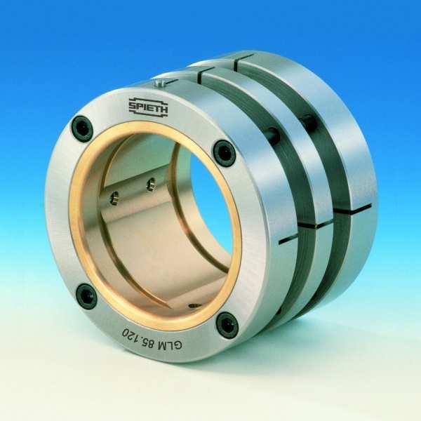
1 SPIETH Hydrodynamic Radial-Slide-Bearings Series GLM Works Standard SN 03.01
2 2
3 Content Page 1. General SPIETH Hydrodynamic Radial-Slide-Bearing Hydrodynamic lubrication Lubrication solvent Lubrication System Sealing 5 2. Adjustable SPIETH Radial-Slide-Bearing Use and preferences Layout and function Execution Connecting Components Housing Spindle Mounting and adjustment of play 8 3. Table of dimensions for Radial-Slide-Bearing Series GLM Calculation of Bearing Ascertainment of load capacity Nomogram I Ascertainment of heating of the bearing Nomogram II Viscosity of standard lubricants Nomogram III Standard values for bearing play Nomogram IV Calculation examples Legend Assembly example 19 3
4 1. General In modern and powerful machines the importance of the spindle bearing is increasing. Solutions for these tasks are offered by roller bearings as well as by slide bearings. Increasing demands for long tool life as well as for surface performance, shape accuracy, and fabrication tolerances of the work pieces has been shown in the last years, that especially at hydrodynamic sectionalised surface slide bearings with its caused by the lubricating film high damping properties and concentric accuracy the smoothness as well as the insusceptibility to shock together with its high durability are characteristics which can barely be featured by roller bearings SPIETH Hydrodynamic Radial-Slide-Bearing SPIETH-slide bearings are hydrodynamic lubricated adjustable sectionalised-surface radial slide bearings. The main use is in the field of mechanical engineering and especially for building machine tools with its complex requirements Hydrodynamic lubrication Hydrodynamic lubrication means the stream caused by a running spindle in the with lubricant filled wedged shaped gap of a slide bearing. This stream cause liquid thrusts in the lubricant with the highest level of thrust short before the smallest gap in running direction. At correct arrangement of wedged shaped gap, spindle revolutions and oil viscosity the created liquid thrust is able to lift even high loaded spindles from the bearing surface. The effect is that the spindle is >>swimming<< above the lubricant layer Lubricant Used for lubrication are mineral oils, mainly spindle oils. Their viscosity has to be chosen in dependence of the working conditions. For hydrodynamic lubricated slide bearings an adequate supply of oil is required for problem free running. The function of the lubricant hereby is not only to create the hydrodynamic thrust in the wedged shaped gap, it also has to transfer the friction heat out of the region of the slide surfaces Lubrication system The most used lubrication systems are: Splash lubrication, centrifuge lubrication and external lubrication 4
5 The external lubrication by a pump is the most secure and efficient lubrication system. Especially for high sliding speeds which need a high quantity of oil for cooling the external lubrication supply by a pump is absolutely necessary. For this lubrication system any spindle position can be allowed. There is only the need for sufficient pump pressure to negotiate circuit and duct resistance to ensure an adequate quantity of oil for the temperature equation. As said before, the carrying liquid thrust will be created by itself after the rotation of the spindle has started Sealing Slide bearings are provided with gaskets to avoid the escape of the lubricant out of the inner system and also to protect the bearing system against penetration of dirt and humidity. The sealing system is dependent of the working conditions. Contact or sliding gaskets are used for low and middle velocities. The wear and friction heat limits its use. The application area is up to the peripheral speed of 12 m/s. Higher sliding speeds require non-contact gaskets such as a pressure-tight sealing thread, labyrinth sealing or an annular gap with a loose inserted bronze sliding ring. As in the annular gap a hydrodynamic thread will be created by the spinning spindle, which is higher than the regular pressure of the lubricant, no oil can escape while the spindle is running. All non-contact sealing have a little amount of leaking oil as long as the spindle is not running. As this is known, this can be absorbed and returned to the lubricant tank. 2. Adjustable SPIETH Radial-Slide-Bearing 2.1. Use and preferences This hydrodynamic sectionalised radial slide bearing is used wherever optimum bearing play and highest running smoothness is requested and a sufficient lubrication supply is ensured. High and low frequencies are allowed as same as both directions. As the optimum bearing play can be set and readjusted, no longsome adaptation between bearing and spindle are necessary. It is sufficient if the seating of the spindle and the bore in the housing are machined cylindrical according to an ISO-Tolerance. This adjustable bearing type is today successful used wherever best surface quality, and shape accuracy has to be machined. The GLM is used for spindle bearing in grinding-machines, lathes, precise drilling or as counter bearing of milling arbor and boring bars. For this machinery there are for example grind and work piece spindles with a GLM bearing in use to realize a concentricity of less than 0,4 µm. One of the most underestimated advantages of the Type GLM bearing is the damping effect of the hydrodynamic bearing system. The high absorbability of the hydrodynamic guidance is very useful for machining processes where high frequencies can occur due to the high durability of the static elements. 5
6 2.2. Layout and function The SPIETH hydrodynamic radial slide bearings have a meander formed profiled steel hull (a) with integrated clamping screws (b) and a bearing bush made out of bearing bronze (c). The bearings are configured in a way, that after tightening the clamping screws first the mounting play (S 1 + S 2 ) will be eliminated. After this the radial strangling of the inner bearing bush will start. This strangling will be in a parallel direction to the axis. It is possible to set any requested bearing play or adjustment without any scraping. Fig. 3: a b c d e f g h i S S 1 S 2 r R iron hull clamping screws bushing lubrication flute lubrication hole outer cut-in lubrication inlet lubrication outlet cylindrical pin bearing play mounting play mounting play shaft-radius slide-radius The inner bushing has some axial lubrication flutes (d) which are connected with the outer cut-in (f) in the steel hull by radial lubrication holes (e). By this arrangement the bushing is connected with the lubrication inlet (g) and outlet (h) in the housing bore. 6
7 The lubrication flutes are dividing the bushing bore in a few sliding surfaces. During the adjustment of bearing play, these sliding surfaces are changing their original radius in the way, that there will arise a wedge crack between sliding surface and spindle. The tightest point of this wedge crack will be in the middle of the sliding surface and will expand in both directions to the lubrication flutes. SPIETH hydrodynamic radial slide bearings are independent of the rotation direction of the spindle as the lubricant can flow under the developed pressure in the squeezed wedge crack and can thereby lift the spindle from the bearing sliding surface. Due to physical rules, the hydrodynamic lubrication process is all round the spindle and therefore centring the spindle unavoidable. The radial orientation of the bearing in the housing bore will be realized by a cylindrical pin (i) which will fit in a flute to be machined in the housing Execution The meander formed steel hull working as an adjustment element is made out of special steel and not hardened. The bushing is made out of high grade bearing bronze. This material was chosen for high security reasons and due to its emergency running properties as during the short period of start-up and run-out the lubrication layer may be interrupted and a metal contact between spindle and bearing sliding surface may occur. The outer diameter of the bearing is grinded according to the tolerance h5; the bore is machined to F6. As the bearing is machined under compressed conditions, a control measurement of the bore is not possible in its untensioned delivery state. The mounted clamping screws shall be tightened by using a wrench according to ISO Connecting Components Housing The housing bore has to be machined cylindrically according to the tolerance H6. The radial orientation of the bearing is done by a cylindrical pin of the bearing, aligned in a flute to be machined in the housing. Normally the orientation is chosen in a way, that the direction of the bearing load is about 6 before one of the sliding surface centre out of the rotation direction. The lubrication supply has to be done in a way, that the lubricant can be feed into the outer cut-in of the steel hull of the bearing. The lubricant return circuit will be dependent of the working conditions through the second outer cut-in and/or through outpouring side wards as leak oil. Return circuit and leak oil will be conveyed to the reservoir. For horizontal spindles it may be practical to install the supply and return from the top. At vertical spindles the supply should be beneath, the return above. 7
8 Spindle For an accurate concentricity the spindle contact surface has to be done cylindrically according to tolerance g5. Recommended quality of the spindle is a surface roughness of 0,4 0,63 µm best realized by smooth grinding. The material of the spindle is dependent of the requirements. For high operational demands the spindle should be case hardened ( HRC 64) or nitrogen hardened ( HV 8500 N/mm 2 ). Regarding to the for bearing play adjustment necessary control of contact pattern we recommend following for using two bearings with the same size: The diameter of the first to insert spindle-bearing seat should be machined with a reduction of IT3. The result will be that passing the second bearing during dismounting will not smear the visible areas of a die spotting Mounting and adjustment of play To inform every first time user detailed, every delivery is equipped with an extensive instruction. Further instructions are available under request. Basic requirement for proper bearing function is an accurate cleaning of all lubrication-conveying holes, and lines. Left over from fabrication or other particles are removed best by pressure flushing with heated (warm) low viscosity machine oil Dismantling of clamping screws, greasing of thread and contact surface of screw head. Screw the screws back on place until contact of screw head contact face, but do not tighten more to avoid pretension Insert the radial-plain-bearing into the housing, pay attention that the orientation pin must not come to rest axially against the groove in the housing. Tighten the clamping screws evenly crosswise until the radial-plain-bearing is seated firmly in the housing. Even actuation of the clamping screws can be achieved by tightening in each case by a certain angular amount (e.g.30 ) Insert the spindle into the borehole of the radial-plain-bearing. Adjust on each spindle end a micrometer for concentricity. Pay attention that the radial play, cause by radial movements, is measured in the direction of the clamping screws and as near as possible to the radialplain-bearing Reduce bearing play on both bearings by tightening the clamping screws crosswise until the play is 0,01 mm bigger than the wanted movement play. After each tightening sequence hit the spindle a few times lightly with a rubber mallet in the direction of the clamping screws. It could happen, that the bearing play will increase by this treatment, but this is intended. 8
9 As the bearing play is now 0,01 mm bigger than the wanted movement play, remove the spindle and apply a coating of inking paste. To assess the contact pattern by the left ink impression, the coating of the inking paste has to be kept real thin Reinsert the spindle into the radial-plain-bearing and generate a contact pattern by radial and axial movements of the spindle. Remove the spindle and assess the ink impressions left If the contact pattern in the radial-plain-bearing is equally at all sliding sections, the final movement play can be set by tightening the clamping screws as described above. If the contact pattern is uneven, the clamping screws shall be tightened individually depending on the ink impressions. This could result in a one-sided adjustment. If the movement play was set too closed, all screws have to be loosened until play is 0,01 0,02 mm bigger. The play has to be set again as described above. The complete adjusting range correspond approx. the basic tolerance field IT 10 based on the spindle diameter. 9
10 3. Table of dimensions for Radial-Slide-Bearing Series GLM ISO 2338 ISO 4762 Code GLM GLM GLM GLM Designation of an adjustable hydrodynamic radial slide bearing with d 1 = 40 mm, d 2 = 65 mm, and L = 45 mm: Radial slide bearing GLM dimensions in mm cylindrical pin ISO clamping screws d 1 d 2 L l 1 l 2 d 3 d 4 c l 3 α dimensions n F6 1) h5 max mm mm mm ISO No ,8 12,5 4 M 4 x M 4 x 40 GLM ,8 16,5 6 M 5 x 45 GLM ,8 18, M 5 x GLM ,3 21,5 M 5 x GLM , M 6 x 60 GLM , M 6 x 65 GLM M 6 x GLM M 6 x 75 GLM ,8 29,5 GLM ,8 30,5 15 M 6 x 80 GLM M 6 x GLM ,3 35,5 20 M 6 x 90 GLM ,8 40,5 M 8 x 100 GLM ,5 43 M 8 x 110 GLM M 8 x 120 GLM ,5 53 M 8 x 130 1) see chapter 2.3. subject to change without notice
11 4. Calculation of Bearing With the here presented method the designer is given the possibility to collect the for bearing definition needed but unknown values by graphic method. This method is easy and sufficient enough Ascertainment of load capacity (Nomogram I) The SPIETH hydrodynamic radial slide bearing Type GLM has nearly wedge shaped retain fields in defined geometric dimensions. Therefore the load bearing capacity is according to technical literature: l F = C η u b h 2 2 o The smallest operational lubrication gap is according to technical literature about the size of h o 2µ m Due to this h o < t b = supporting bearing width can be ascertained and the load rating C displayed as: h C 0,25 t o For the geometric of the GLM the load bearing capacity F can be calculated as: d F 30η u h 2 o and the average high loading pressure p : F p = l b 150η u 1 h o Nomogram I was compiled for the smallest lubrication gap occurring under operation ηis the dynamic viscosity under working temperatures. h o 2µ m ; 4.2. Ascertainment of heating of the bearing (Nomogram II) Out of the for wedge shaped retain field named relations η u µ (0,5...1) p there is the outcome of the friction coefficient h o µ
12 and the friction loss P = F u In the diagram of Nomogram II are two overlapping cases displayed: Case 1: heat emission at the bearing surface. At an exothermic surface A 10 d 2 and the heat transmission number W α = 20 K m 2 the dissipation of friction loss at the bearing surface P = α A T air As a result of this, the high temperature of the bearing is P Tair K air ; 2 d whereby K air K m = 0,005 W 2 In this case the high temperature will be ascertained with the diameter scale in the Nomogram II. Case 2: heat emission to the coolant At a supposed specific heat Nm c = 1900 kg K and a density of the coolant 3 ρ = 0, [ kg / m ] the dissipated friction loss by the quantity of coolant Q is P = ρ c Q T oil As a result of this, the high temperature of the bearing is P K I Toil K oil ; whereby K oil 0,03 Q W min The high temperature will be determined by the scale of the coolant quantity in the Nomogram. 12
13 4.3. Viscosity of standard lubricants In the Nomogram III the dynamic viscosity η of some standard lubricants in dependency of the working temperature can be ascertained Standard values for bearing play The bearing play is the resulting difference of the adjusted diameter of the bearing sliding surfaces and the diameter of the shaft. In the Nomogram IV there are standard values for the bearing play, graded in dependence of the bearing size and the allowed high temperature Calculation examples bearing Reading description code dimensions case 1 heat emission at the bearing surface case 2 heat emission through the coolant Nomogram I and II N'gr. III diameter (spindle) d mm load capacity F kn 3,6 8,7 revolutions per minute n 1/min peripheral speed u m/s 1,3 13 average surface pressure p N/mm 2 3,6 5,6 working viscosity η mpa s 34 5,4 high temperature T K friction loss P W coolant quantity Q l/min - 1,25 working temperature T C kinematical viscosity υ mm 2 /s 134 at 20 C 10 at 20 C N'gr. IV bearing play standard value S µm 18,
14 Nomogram I
15 Nomogram II 15
16 Nomogram III kinematic viscosity dynamic viscosity Approx viscosity run of standard lubrication oils calculation of ν in η at an average oil density of ζ=0, kg/m 3 temperature C 16
17 Nomogram IV 17
18 4.6. Legend F = load capacity η = dynamic viscosity at working temperature u = peripheral speed d = diameter (shaft) p = average surface pressure P = friction loss Q = coolant quantity T = high temperature (difference between working- and coolant supply temperature) T = working temperature ν = kinematical viscosity s = bearing play 18
19 5. Assembly example Headstock with open housing The adjustable hydrodynamic sectionalised radial slide bearings GLM are mounted directly in the bores of the headstock. The axial guiding is placed between the GLM, adjusted for correct play and tightened with a SPIETH-Locknut against the spindle accretion. V-rings are used for sealing against oil loss. 19
20 No part of this publication may be reproduced in any form without our prior permission. Although the specifications and information provided in this catalogue are compiled and checked for correctness with the greatest care, we are unable to accept liability for any errors or omissions which may have been overlooked. SN e 0409/0000/ SPIETH-Maschinenelemente GmbH & Co KG Alleenstrasse Esslingen 20
SPIETH Locknuts. Series MSW. Works Standard SN 04.03
 SPIETH Locknuts Series MSW Works Standard SN 0.03 SPIETH Locknuts Series MSW SPIETH locknuts offer a range of technical benefits, qualified by their special system and production. Under high levels of
Design Guide. Original version of the design guide
 Page 1 of 12 Original version of the design guide For Series Components Spieth locknuts (precision locknuts) MSR 58x1.5 MSR 60x1.5 MSR 60x2 MSR 62x1.5 MSR 65x1.5 MSR 65x2 MSR 68x1.5 MSR 70x1.5 MSR 70x2
BEARING AND TYPES OF BEARING
 BEARING AND TYPES OF BEARING In this article, you will learn about bearing and types of bearing. Generally, all types of machinery are provided with supports for rotating shafts, the supporting device
KBS 40 Locking Device is a frictionally engaged detachable shaft-hub connection for cylindrical shafts and bores without keyway.
 KBS 40 Locking Device is a frictionally engaged detachable shaft-hub connection for cylindrical shafts and bores without keyway. KBK Antriebstechnik GmbH Page 1 Features - delivered in mounted condition
Assembly Instructions. Original version of assembly instructions
 Page 1 of 7 Original version of assembly instructions For Series Components Spieth locknuts (precision locknuts) MSR 10x0.75; MSR 10x1; MSR 12x1; MSR 12x1.5; MSR 14x1.5; MSR 15x1; MSR 16x1.5; MSR 17x1;
Design Guide. Original version of the design guide
 Page 1 of 14 Original version of the design guide For Components Short Long Compact Short Long Compact Spieth clamping set (precision clamping sets) - 14.2-40.1 40.2 40.56 16.1 16.2 16.28 42.1 42.2 42.58-18.2
Trunnion bearing housings for grinding mills FSDR.. K series
 Trunnion bearing housings for grinding mills FSDR.. K series Bearing types Spherical roller bearings Bearing dimension series 39, 48 and 49 Shaft diameter range 825 to 1 460 mm Typical bearing-shaft combinations
HMZ Locknuts simple and reliable locking devices
 simple and reliable locking devices Technical Product Information A Member of the Schaeffler Group Application Characteristics Application The new HMZ locknuts are easy to handle, permitting accurate and
KRW bearing solutions for rotary tables
 KRW bearing solutions for rotary tables All data have been prepared with a great deal of care and checked for their accuracy. However, no liability can be assumed for any incorrect or incomplete data.
KRW bearing solutions for rotary tables
 KRW bearing solutions for rotary tables All data have been prepared with a great deal of care and checked for their accuracy. However, no liability can be assumed for any incorrect or incomplete data.
Operating Instructions
 Page 1 of 10 Original version of the operating instructions For Series Components Spieth locknuts (precision locknuts) MSR 58x1.5 MSR 60x1.5 MSR 60x2 MSR 62x1.5 MSR 65x1.5 MSR 65x2 MSR 68x1.5 MSR 70x1.5
WHAT? WHERE? HOW?
 JIGS WHAT? WHERE? HOW? Introduction Mass production aims at high productivities to reduce unit cost and inter-changeabilites to facilitate easy assembly. Jigs are useful in mass production. They provide
Workpiece Clamping. Collets for Workpiece Clamping Collet Chucks for Workpiece Clamping
 Workpiece Clamping Collets for Workpiece Clamping Collet Chucks for Workpiece Clamping Overview of Contents Page Collets for Workpiece Clamping Draw-in Collets DI 2 Dead Length Collets DL 3 Emergency Dead
DODGE Grease Lubricated SPLIT-SPHER Roller Bearings and Pillow Blocks
 Mounting Instructions For DODGE Grease Lubricated SPLIT-SPHER Roller Bearings and Pillow Blocks WARNING: Because of the possible danger to person(s) or property from accidents which may result from the
Ensat driving tools...
 nsat driving tools... On this page, you can configure the optimum tool for your application. A configuration is provided in the following as an illustrative example. The article number is composed of two
High-precision inch guide units Made in Germany
 High-precision inch guide units Made in Germany cm 1 2 3 4 5 6 7 8 9 10 11 12 13 14 15 16 17 18 19 20 cm inch inch 1 2 3 4 5 6 7 8 STEINEL All you need for tools Your partner for punching and bending
Various other types of drilling machines are available for specialized jobs. These may be portable, bench type, multiple spindle, gang, multiple
 Drilling The process of making holes is known as drilling and generally drilling machines are used to produce the holes. Drilling is an extensively used process by which blind or though holes are originated
SKF filament wound bushings
 SKF filament wound bushings The maintenance-free heavy-duty bushing High load carrying capacity Corrosion resistant Maintenance-free Maintenance-free, durable, cost-effective Filament wound material provides
Vertical and horizontal Turning/Grinding Centers
 Vertical and horizontal Turning/Grinding Centers INDEX Turning/Grinding Centers Turning and grinding of course with INDEX The INDEX Turning/Grinding Centers combine the advantages of turning and grinding
Assembly Instructions DSK/DSL. Original version of assembly instructions
 Page 1 of 6 Original version of assembly instructions For Components DSK 14.26 DSL 14.26 DSK 30.42 DSL 30.42 DSK 50.75 DSL 50.75 DSK 140.170 DSL 140.170 DSK 14.26 DSL 15.28 DSK 30.47 DSL 30.47 DSK 50.80
Catalog October Speedi-Sleeve The quickest and most economical way to repair worn shafts
 Catalog 457027 October 2005 Speedi-Sleeve The quickest and most economical way to repair worn shafts Table of Contents The Speedi-Sleeve concept...3 SPEEDI-SLEEVE, the quickest and most sensible way to
Installation and Operating Instructions for Shrink Discs RLK 608 and RLK 608 E E e
 for Shrink Discs RLK 608 and RLK 608 E E 03.621e Schaberweg 30-34 Telephone +49 6172 275-0 61348 Bad Homburg Telefax +49 6172 275-275 Germany www.ringspann.com info@ringspann.com issue: 26.10.2018 version
ROOP LAL Unit-6 Lathe (Turning) Mechanical Engineering Department
 Mechanical Engineering Department") Notes: Lathe (Turning) Basic Mechanical Engineering (Part B) 1 Introduction: In previous Lecture 2, we have seen that with the help of forging and casting processes, we can manufacture machine parts of
Notes: Lathe (Turning) Basic Mechanical Engineering (Part B) 1 Introduction: In previous Lecture 2, we have seen that with the help of forging and casting processes, we can manufacture machine parts of
DRIVE COMPONENTS REMOVAL. 9. FXCW/C: see Figure Remove bolt (9), sprocket retainer (8), and thrust washer (7). NOTE PRIMARY DRIVE LOCKING TOOL
, sprocket retainer (8), and thrust washer (7). NOTE PRIMARY DRIVE LOCKING TOOL") DRIVE COMPONENTS REMOVAL PART NUMBER HD-7977 TOOL NAME PRIMARY DRIVE LOCKING TOOL S To remove the primary chain, remove compensating sprocket, clutch assembly and primary chain as an assembly:. Remove
DRIVE COMPONENTS REMOVAL PART NUMBER HD-7977 TOOL NAME PRIMARY DRIVE LOCKING TOOL S To remove the primary chain, remove compensating sprocket, clutch assembly and primary chain as an assembly:. Remove
PRODUCTS & SERVICES GUIDE
 PRODUCTS & SERVICES GUIDE IT S YOUR MOVE. 2 ROCKFORD BALL SCREW ABOUT US Ian McBain founded Rockford Ball Screw (RBS) in 1973 utilizing his years of experience in the industry with the goals of providing
WM en. Zero point clamping system system 3000
 Zero point clamping system system 3000 unique push-on very strong automatic monitoring flush mounted SPEEDY and spigot handling without interfering contour 50kN retention force suitable for automation
Assembly instructions
 Assembly instructions Important notes on VOSS assembly instructions In order to ensure maximum performance and functional reliability of VOSS products, the respective assembly instructions, operating conditions
PEDESTAL OVERHAUL. Some of the tools for a pedestal overhaul. Pedestal work stand
 INTRODUCTION A properly greased labyrinth seal will help prevent dust and water damage to the pedestal bearing oil supply and shaft seal area. Properly greased and oiled pedestals rarely require an overhaul.
Technical features. Positive Taper Lock System for manual tool clamping. Technical features:
 clamping set Technical features The RÖHM- was specially designed for the positive taper lock clamping taking particulary into account the necessity of manual clamping. Technical features: strong design
CLAMPEX KTR 401 Operating/Assembly instructions. 1 Technical data 2
 1 of 8 The CLAMPEX clamping set is a frictionally engaged, detachable shaft-to-shaft connection for cylindrical shafts and bores without feather key. Table of contents 1 Technical data 2 2 Advice 3 2.1
INSTRUCTIONS FOR USE A1 & A2 KNURLING TOOLS
 INSTRUCTIONS FOR USE A1 & A2 KNURLING TOOLS Contents CONTENTS 1. General... 2 1.1 Introduction... 2 1.2 Tool Construction... 3 2. A1-Tools... 5 2.1 Technical Data... 5 2.2 Overview: Main Components...
Roller Guides C-Rail Systems Linear Guide Systems Ball-Bearing Guide Bushes Ball-bush block guides Shafts Accessories for Linear Slides
 Roller Guides C-Rail Systems Linear Guide Systems Ball-Bearing Guide Bushes Ball-bush block guides Shafts Accessories for Linear Slides Application example linear systems, drives and accessories 1 2 3
Clamping devices 521
 Clamping devices 521 522 Product overview Clamping devices Adjustable straps K0001 Hook clamps K0012 Goose-neck straps with long slot K0002 Page 526 Hook Clamps with collar K0013 Page 535 Equipped clamps
HDL(M)6 Nut/Screw Assembly
6 Nut/Screw Assembly") HDL(M)6 Nut/Screw Assembly Remove, repair, and reassemble the nut and screw assembly in your HDL series double lock vise. In these instructions when we refer to the front of the vise or nut/screw assembly,
HDL(M)6 Nut/Screw Assembly Remove, repair, and reassemble the nut and screw assembly in your HDL series double lock vise. In these instructions when we refer to the front of the vise or nut/screw assembly,
Precision Double Row Cylindrical Roller Bearings With Tapered Bore
 Roller Bearings With Tapered Bore High precision cylindrical roller bearings are bearings with a low cross section, high load carrying capacity and speed capability. These properties make them particularly
10/24/2011. Chapter 3
 Chapter 3 Exact alignment Availability to compensate wear Minimum friction Ease of assembly and economy of manufacture Freedom from restrain Prevention of chip and dirt accumulation Effective lubrication
INSTALLATION & MAINTENANCE
 INSTALLATION & MAINTENANCE 1441 Wolf Creek Trail, P.O. Box 305 Sharon Center, OH 44274 330-239-4933 www.pttech.com PTT-381-0 Table of Contents Safety... 2 Description... 3 Pre-Installation Check... 6 Maintenance
INSTRUCTION MANUAL Q-HYDRAULIC
 Dat: 15.04.02 No: 94-BA 5039E/1b TABLE OF CONTENTS Part III 3.0 Type code explanation 3.1 Service connections 3.2 Impeller clearance adjustment 3.2.1 Wear of wearing parts 3.2.2 General notes to adjustment
HC Hydraulic Expansion Chucks
 Technical Information HC Hydraulic Expansion Chucks design, function, effect, and application features, handling, and action application instructions precision tool length setting torques accessories sealed
INSTRUCTIONS FOR USE B2 FORM KNURLING TOOL
 INSTRUCTIONS FOR USE B2 FORM KNURLING TOOL Contents CONTENTS 1. General... 2 1.1 Introduction... 2 1.2 Tool Construction... 3 2. B2 Tools... 6 2.1 Technical Data... 6 2.2 Overview: Main components... 7
Installation and Operational Instructions for ROBA -DS couplings Type 95. _ (disk pack HF) Sizes
 Sizes") 95. _ (disk pack HF) Sizes 6 22 Please read these Operational Instructions carefully and follow them accordingly! Ignoring these Instructions may lead to malfunctions or to coupling failure, resulting
95. _ (disk pack HF) Sizes 6 22 Please read these Operational Instructions carefully and follow them accordingly! Ignoring these Instructions may lead to malfunctions or to coupling failure, resulting
TOP WORK ISO 9001.CE UNIVERSAL CUTTER & TOOL GRINDER
 TOP WORK ISO 9001.CE UNIVERSAL CUTTER Precise ball groove of conformation Inclination of Wheelhead The wheelhead can easily tilt up to ±15 degrees, with a 360-degrees swivel on the horizontal plane. The
Installation and operating instructions for Brake disc with clamping element RLK 608 E Schaberweg Telefon
 Brake disc with clamping element RLK 608 E 09.683 Schaberweg 30-38 Telefon +49 6172 275 0 61348 Bad Homburg Telefax +49 6172 275 275 Deutschland www.ringspann.com info@ringspann.com Issue: 07.06.2017 Version:
5 Maintenance 5.1 Guideway and Wipers
 5 Maintenance 5.1 Guideway and Wipers 5.1 Page 26 of 41 The grinding carriage runs with hardened rollers on hardened steel straps (2). The steel straps (2) are positioned on the grinding bed (1) and tensioned
Clamping bolts Eccentrical cams clamping units
 2.3 Shaft Clamping bolts Eccentrical cams clamping units 2.9 2.8 2.7 2.6 2.5 2.4 2.3 2.2 2.1 2.3 Clamping bolts, Eccentrical cams, Shaft clamping units Page 641 2.3 Clamping bolts, Eccentrical cams, Shaft
The Ensat self-tapping threaded insert...
 The nsat self-tapping threaded insert... nsat is a self-tapping threaded insert with external and internal thread, cutting slots or cutting bores. A continuous process of further development has brought
COYOTE ENTERPRISES, INC. RIMLOC BLAST WHEEL MAINTENANCE & ASSEMBLY MANUAL
 COYOTE ENTERPRISES, INC. RIMLOC BLAST WHEEL MAINTENANCE & ASSEMBLY MANUAL Parts & Machinery for the Abrasive Blast Industry 27301 East 121st Street Coweta, Oklahoma 74429 (918) 486-8411 Fax (918) 486-8412
bcprecision Devices, Inc. HYDRAULIC ARBORS AND CHUCKS
 UNEQUALED WORK HOLDING ACCURACY for: grinding; balancing; inspection; boring; facing; reaming; drilling; turning; shaving; hobbing and honing b SQUARENESS r CONCENTRICITY f PARALLELISM e ROUNDNESS v ALIGNMENT
Maintenance Information
 16601023 Edition 2 January 2014 Air Impact Wrench 2705P1 Maintenance Information Save These Instructions Product Safety Information WARNING Failure to observe the following warnings, and to avoid these
Motorized M3 AX7200 Rotary-Style Gasket Cutter Operating Instructions
 Motorized M3 AX7200 Rotary-Style Gasket Cutter Operating Instructions INTRODUCTION Congratulations! You are the owner of the finest rotary-style gasket cutter in the world. Originally developed and patented
SNOE 200 SNR bearing housings
 Assembly, servicing and maintenance instructions SNOE 200 SNR bearing housings N TS5142 www.ntn-snr.com With You Contents 1. Types of housing with oil-lubricated pillow block 2. Preparation for assembly
The Ensat self-tapping threaded
 The nsat self-tapping threaded insert nsat is a self-tapping threaded insert with external and internal threads,cutting slots or cutting bores. A continuous process of further development has brought about
1. TABLE OF CONTENT 2. ASSEMBLY ATEX. PENCOflex Installation Instructions & Service Manual
 ATEX 1. TABLE OF CONTENT 1. Table Of content... 1 2. Assembly... 1 3. Alignment... 2 4. Earthing... 3 5. Inspection and replacement of Elastic elements... 4 5.1. Rubber elements... 4 5.2. Pins... 4 5.2.1
SOFTSYNCHRO HIGH PERFORMANCE TAP H O L D E R S
 SOFTSYNCHRO HIGH PERFORMANCE TAP H O L D E R S You Know Taps Now take them to the next level Triple your tap life and more with Emuge Softsynchro Tap Holders! E muge is widely recognized in the industry
400 SERIES GRINDER PUMPS 41502, 42202,43302, AND MODELS
 Section: MOYNO 500 PUMPS Page: 1 of 6 Date: March 1, 1998 SERVICE MANUAL MOYNO 500 PUMPS 400 SERIES GRINDER PUMPS 41502, 42202,43302, AND 44402 MODELS DESIGN FEATURES Housing: Cast iron Pump Rotor: Chrome
Assembly and Adjusting Instructions for Modules 6x6 and 4x4 Alignment Adapter
 Translated version of the instructions Version: 11/2017 SAP no.: 400151427 Assembly and Adjusting Instructions for Modules 6x6 and 4x4 Alignment Adapter The document was prepared by Gühring KG. All rights
Assembly instructions
 Assembly instructions Important notes on VOSS assembly instructions In order to ensure maximum performance and functional reliability of VOSS products, the respective assembly instructions, operating conditions
APRIL 2009 / NEW-100 / PAGE 1 OF 13
 APRIL 2009 / NEW-100 / PAGE 1 OF 13 The standard UNIDEX line covers reaming applications from 5/16 to 1 1/4 diameter. The single indexable blade and high wear resistant carbide or cermet pads provide a
Lathe. A Lathe. Photo by Curt Newton
 Lathe Photo by Curt Newton A Lathe Labeled Photograph Description Choosing a Cutting Tool Installing a Cutting Tool Positioning the Tool Feed, Speed, and Depth of Cut Turning Facing Parting Drilling Boring
. Dimensions of the Machine Spindle Heads in Compliance with DIN The most recent editions of the DIN standards are binding.
 Clamping technology. Dimensions of the Machine Spindle Heads in Compliance with DIN The most recent editions of the DIN standards are binding. DIN 55026 Taper sizes 4 and above with drive tang. Spindle
REPAIR INSTRUCTIONS. Cat. No Cat. No MILWAUKEE ELECTRIC TOOL CORPORATION. SDS Max Demolition Hammer. SDS Max Rotary Hammer
 Cat. No. 9-0 SDS Max Demolition Hammer Cat. No. -0 SDS Max Rotary Hammer MILWAUKEE ELECTRIC TOOL CORPORATION W. LISBON ROAD BROOKFIELD, WISCONSIN 00-0 8-9-0 d 000 8-9-0 d Special Tools Require Forcing
KTM-16/20 TECHNICAL DATA
 TECHNICAL DATA Table Diameter : 1,600mm Max. Turning Diameter : 2,000mm Max. Turning Height : 1,750mm Table Indexing Degree : 0.001mm CNC Controller : FANUC 18i-TB ** Bed The bed has symmetrical structure
Screws. Introduction. 1. Nuts, bolts and screws used to clamp things together. Screws are used for two purposes:
 Screws Introduction Screws are used for two purposes: 1. To clamp things together. 2. To control motion. 1. Nuts, bolts and screws used to clamp things together. Nuts, bolts and screws that are used for
REPLACING THE CAT SEAL IN THE 90AD EXTRUDER
 T S B D S D 0 0 0 4 T E C H N I C A L S E R V I C E B U L L E T I N REPLACING THE CAT SEAL IN THE 90AD EXTRUDER 1-8 0 0-2 7 8-3 3 5 3 w w w. j c s t e e l e. c o m 2018 J.C. Steele & Sons, Inc. SAFETY
ROTARY TABLE OPERATION AND SERVICE MANUAL HORIZONTAL AND VERTICAL. Horizontal & Vertical. Rotary Table (HVRT) Tilting Rotary Table
 Tilting Rotary Table") Horizontal & Vertical Rotary Table (HVRT) OPERATION AND SERVICE MANUAL Tilting Rotary Table Horizontal & Vertical Rapid Indexer VERTICAL AND HORIZONTAL ROTARY TABLE This Horizontal & vertical table is
Horizontal & Vertical Rotary Table (HVRT) OPERATION AND SERVICE MANUAL Tilting Rotary Table Horizontal & Vertical Rapid Indexer VERTICAL AND HORIZONTAL ROTARY TABLE This Horizontal & vertical table is
Removing Right-Side. Components. Right-Side. Components. Click Here to Go Back AT THIS POINT
 Click Here to Go Back NOTE: There is an oil passage beneath the driven gear/drive gear assembly. This passage should be plugged prior to removing the driven gear and drive gear. Failure to do so could
TCF 160 / TCF 200 / TCF 224 / TCF 250 TCF 275 / TCF 300 HEAVY CENTRE LATHES
 TCF 160 / TCF 200 / TCF 224 / TCF 250 TCF 275 / TCF 300 HEAVY CENTRE LATHES BASIC PARAMETERS 3-guideways bed Max. torque on spindle Nm Max. weight of workpiece between centre 30 tonnes Turning length 3,000
SERVICE PARTS LIST. M18 FUEL SAWZALL Reciprocating Saw F56A BULLETIN NO CATALOG NO
 47(5x) 46 45 00 44 0 59 43 42 84 51 57 46 47 48 59 83 64 77 48 47(2x) 49(2x) 40 58 See service note on page 5 41 82 51 40 41 42 43 44 45 87 52 27 28 34 57 29 (6x) 60 28 EXAMPLE: Component Parts (Small
Technical Manual. ETP-CLASSIC incl type R. Content
 Technical Manual ETP-CLASSIC incl type R Content Technical parts description...2 Mounting/dismantling tips...4 Design suggestions...7 Tolerances...13 Central bolt...15 Torsional stiffness...16 Screw pitch
CQ Tilting Pad Thrust Bearings
 CQ Tilting Pad Thrust Bearings Installation and Maintenance Instructions 1. Introduction The following notes provide installation and assembly instructions for Waukesha Bearings CQ tilting pad thrust bearings.
Hydraulic Clamp Carrier. Installation & Operation Manual
 Hydraulic Clamp Carrier Installation & Operation Manual Hydraulic Clamp Carrier Installation & Operation Manual Quick Machinery Company 8272 Peninsula Drive Kelseyville, CA 95451 phone: (707) 272-6719
YALE FIGURE 500 & 500R CLOSURE OPERATION AND MAINTENANCE INSTRUCTIONS
 YALE FIGURE 500 & 500R CLOSURE OPERATION AND MAINTENANCE INSTRUCTIONS IMPORTANT INFORMATION Note To Supervisor: Please share this information with your employees and make sure they have received training
Reaming and fine boring. EasyAdjust-System Simpler, faster, more cost-effective
 Reaming and fine boring EasyAdjust-System Simpler, faster, more cost-effective Never before it had been possible to adjust tools so fast and at such a precision. 2 MAPAL EasyAdjust-System Introduction
EURO-BEARINGS LTD COMBINED ROLLER BEARINGS & MATING STEEL PROFILES
 EURO-BEARINGS LTD & MATING STEEL PROFILES For fork lift trucks, overhead cranes, track conveyors and heavy duty linear motion systems... The axial (side thrust) roller runs on the web of the channel whilst
HBS-AP ASSEMBLING INSTRUCTIONS
 ALUMINIUM PIPEWORK - ALUMINIUM PIPEWORK - ALUMINIUM PIPEWORK 97 HBS-AP ASSEMBLING INSTRUCTIONS 1. INTRODUCTION 1.1. This manual is very easy to consult and we recommend reading it before starting work,
QB78 CO 2 Pellet Rifle
 QB78 CO 2 Pellet Rifle Maintenance Instructions Text and photos by George Fox Lang The Chinese QB78 pellet rifle is one of the nicest and most popular CO 2 rifles ever produced. Here are the long-wanted
High Precision Air Chucks
 Precision Workholding Solutions High Precision Air Chucks www..com Improve productivity and lower the cost of secondary machining operations..... through high concentricity. Holding close concentricity
Engineering Data Single Reduction Parts List Item # Description Basic Single Reduction Unit 1. Gear Housing 2. Pipe Plug 3. Vent Plug 4. Splash Guard
 Engineering Data Single Reduction Parts List Item # Description Basic Single Reduction Unit 1. Gear Housing 2. Pipe Plug 3. Vent Plug 4. Splash Guard 5. Input Cover 6. O-Ring 7. Hex Head Cap Screw 8. Input
SINUMERIK live: turning technologies longitudinal turning and plunge-turning. Differences and use with SINUMERIK Operate
 SINUMERIK live: turning technologies longitudinal turning and plunge-turning Differences and use with SINUMERIK Operate siemens.com/cnc4you SINUMERIK live - Application technology explained in an easily
Tools for the Mechanical Mounting and Dismounting of Rolling Bearings
 Tools for the Mechanical Mounting and Dismounting of Rolling Bearings Contents Page Mechanical mounting and dismounting of rolling bearings... 2 Cylindrical bearing seats... 2 Tapered bearing seats...
Typical Group D Rear Acoustical Cover Installation
 SERIES 60 SERVICE MANUAL 1. Gear Case Cover 5. Bolt 2. Gear Case 6. Acoustical Cover 3. Acoustical Cover Snap 7. Acoustical Cover 4. Acoustical Cover Clip 8. Nut Figure 1-179 Typical Group D Rear Acoustical
Inventory MODEL T10096 TAPER ATTACHMENT FOR G0509 & G0509G LATHE INSTRUCTIONS. Inventory (Figure 1) Needed Items
 Needed Items") MODEL T10096 TAPER ATTACHMENT FOR G0509 & G0509G LATHE INSTRUCTIONS Inventory The Model T10096 taper attachment was carefully packed when it left our warehouse. If you discover it is damaged after you
MODEL T10096 TAPER ATTACHMENT FOR G0509 & G0509G LATHE INSTRUCTIONS Inventory The Model T10096 taper attachment was carefully packed when it left our warehouse. If you discover it is damaged after you
PUNCHING DRILLING HEBEN LIFTING CUTTING DEBURRING
 PUNCHING DRILLING LIFTING CUTTING DEBURRING www.alfra.de E-EN E ALFRA Edge-Milling and Deburring Devices Overview KFV KFH 150 Page 7 78 2520 25100 Prism mounting L = 150 / W = 20/40 End mill Ø 45 or straight
Turning and Lathe Basics
 Training Objectives After watching the video and reviewing this printed material, the viewer will gain knowledge and understanding of lathe principles and be able to identify the basic tools and techniques
User s Guide. Silent Tools. turning products
 User s Guide Silent Tools turning products Introduction This guide will help you to use dampened boring bars (Silent Tools) to achieve the best possible results in internal turning. Silent Tools dampened
Adjustable Feet Castors Accessories for Floor Elements
 Adjustable Feet Castors Accessories for Floor Elements Products in this section Levelling Knuckle Feet Threaded spindles for infinite height adjustment Metal or plastic foot plate Knuckle Feet X Compatible
INSTALLATION MANUAL FOR STAINLESS STEEL, GROOVE-END, FLEXIBLE COUPLINGS
 PIEDMONT PACIFIC CORPORATION INSTALLATION MANUAL FOR STAINLESS STEEL, GROOVE-END, FLEXIBLE COUPLINGS 4703 Tidewater Ave., Suite G Oakland. CA, 94601, USA Ph: +1 510 434 0990 / Fax: +1 510 436 0990 www.piedmontpacific.com
World leader in live tools, angle heads, and multi-spindle drill heads
 World leader in live tools, angle heads, and multi-spindle drill heads heimatec GmbH headquarters-germany The Way to Success Heimatec is an international manufacturing company headquartered in Renchen,
MINIATURE METAL BELLOWS COUPLINGS
 VERSATILE AND PRECISE. MINIATURE METAL BELLOWS COUPLINS SERIES MK 0.05 10 Nm THE ULTIMATE COUPLIN FROM 0.05 10 Nm BACKLASH FREE MINIATURE BELLOWS COUPLINS Areas of application: Ideal for precise transmission
18600 Angular Momentum
 18600 Angular Momentum Experiment 1 - Collisions Involving Rotation Setup: Place the kit contents on a laboratory bench or table. Refer to Figure 1, Section A. Tip the angular momentum apparatus base on
Student, Department of Mechanical Engineering, Knowledge Institute of Technology, Salem, Tamilnadu (1,3)
") International Journal of Scientific & Engineering Research, Volume 7, Issue 5, May-2016 11 Combined Drilling and Tapping Machine by using Cone Mechanism N.VENKATESH 1, G.THULASIMANI 2, S.NAVEENKUMAR 3,
International Journal of Scientific & Engineering Research, Volume 7, Issue 5, May-2016 11 Combined Drilling and Tapping Machine by using Cone Mechanism N.VENKATESH 1, G.THULASIMANI 2, S.NAVEENKUMAR 3,
HEAVY DUTY CENTRIFUGAL PUMPS
 HEAVY DUTY CENTRIFUGAL PUMPS Supplemental Assembly Manual DryLock 1 Static Seal Cartridge 1. Place the slide rings (24A & 24B) into the bore of the rotary seal housing (24). The shortest slide ring goes
Operating instructions. Fine boring head Ø3-88 with digital display
 Operating instructions Fine boring head Ø3-88 with digital display English 1. Basic safety information Before first use, please read the operating instructions carefully. These provide important safety
MATERIAL COMBINATION NUMBER 2: Corrosive environment requiring harder, wear-resistant seating faces and resistance to dezincification.
 Cast Iron Slide Gates Spec Sheet General The contractor shall furnish and install the following cast iron slide gate assemblies as listed on the Gate Schedule and detailed on the manufacturer s drawings.
Reinforced all-rubber HSS seals. Reliable protection for large size bearings
 Reinforced all-rubber HSS seals Reliable protection for large size bearings Reinforced all-rubber HSS seals The HSS seals are specially developed by SKF to protect large size bearings under the tough operating
Water Line and Water Line Assembly Gasket
 1 Preparation for Repair 1) Remove tip from scaler 2) Remove scaler from air supply 3) Remove gasket from back end of scaler. Examine gasket for obvious wear or disfigurement. Replace if necessary. 2 Remove
ACCESSORIES CATALOG. SKODA LIVE CENTERS BORING AND FACING HEADS
 ACCESSORIES CATALOG BORING AND FACING HEADS SKODA LIVE CENTERS www.sowatool.com SKODA LIVE CENTERS Skoda Heavy Duty Live Centers - CSN 4334/CSN 4334M Features The rotating spindle is extended right through
website:
 Phone: 1-800-882-0008 (U.S.) Phone: 1-866-832-6753 (Canada) Phone: 1-847-742-7840 (International) Fax: 1-800-526-7268 (U.S. & Canada) Fax: 1-847-742-0261 (International) e-mail: info@skf.com website: http://www.skf.com
RUCKNER. High Performance Live Centres for heavy-duty machining F W ± F S + F F
 High Performance Live Centres for heavy-duty machining High concentricity Shaft seal ring protects the bearings from dirt and coolant Housing high quality material, forged, therefore uniform grain structure,
WM en. Zero point clamping system SPEEDY airtec 1
 SPEEDY airtec 1 GO! Maximum productivity Using the zero point clamping system SPEEDY classic you will increase your productivity to a maximum. Adjustment and checking processes are no longer necessary