Installation Instructions
|
|
|
- Bonnie Jenkins
- 6 years ago
- Views:
Transcription


1 CELEBRATING 50YEARS HIGH PERFORMANCE COMPOSITE SOLUTIONS Installation Instructions DynaRound Guardrail System Building the World to Last

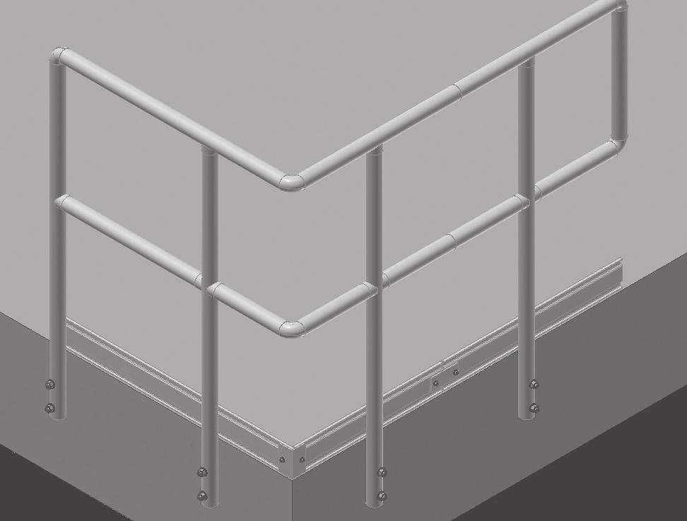
2 Installation Instructions The DynaRound Modular Guardrail System Installation Instructions have been designed to combine the best in fiberglass reinforced plastic (FRP) railing with simplicity of installation. Fibergrate has made every attempt to provide clear and thorough instructions for installing these products. If you have any further questions, or need additional information, do not hesitate to contact Fibergrate at (800) By following these simple instructions, you should find installation of your railing system quick and easy. TOOLS REQUIRED o Drill o Marker or Pencil o Bits o 25' Tape Measure 1/8" (for rivets) o Rivet Gun o o 3/16" (for kickplate and handrail screws) o Rivet Nut Setting Tool (PN ) 3/8" (for rivet nuts) o Socket Set with Extensions 5/16" & 9/16" (for bolts) o Open End Wrench Set 1/2", 82 Countersink (for Midrail to End Post Kit - PN ) 10" Power Miter Saw with Masonry or Carbide Abrasive Blade o Bonding (Epoxy) Kit(s) - one for every 15 posts PN o Spray Sealer (PN Insulating Epoxy 403 Clear, 12.5 oz. can) o Sandpaper (80 grit) - for Deburring Cuts o Blue (removable) or Red (non-removable) Thread Locking Compound o 36" Spirit Level NOTE: Cuts and drilled holes must be sealed to maintain corrosion protection. IMPORTANT Read these instructions completely before attempting to install the DynaRound modular guardrail system. It is important to understand the installation procedure thoroughly prior to beginning work. It is the installer s responsibility to carefully follow fabrication and installation plans and instructions to ensure design performance characteristics of the DynaRound guardrail system. The installer could be liable for claims that result from improper installation. INSTALLING HORIZONTAL GUARDRAIL 1. Install the post kits following the details shown on pages 4 and 5. Posts are to be placed at a maximum of 4-0 (1219 mm) on center for continuous runs and a maximum of 18 inches (457 mm) from Returns, 90 Turns, or Non- 90 Turns. Posts are to be placed at a maximum of 12 inches (305 mm) from a Stub End condition. Insure that the posts are installed plumb. Note: Do not install the Post to Top Rail Kit (PN ) prior to Step 12. (


. The Mid-Rail Length (MRL) is equal to the Post Spacing (PS) minus 3 inches (76.2 mm).")
![GUARDRAIL ELEVATION See Details Guardrail Length (GL) Top Rail Length (TRL) See Details Mid-Rail Length (MRL) = (PS) - 3" [76mm] Post Spacing (PS) PS 4'-0" [1219mm] Max 4.](/docs-images/78/78531982/images/3-3.jpg "Loosen or remove the second post and install the mid-rail by bonding and riveting it to the saddle connectors on the first and second post.")


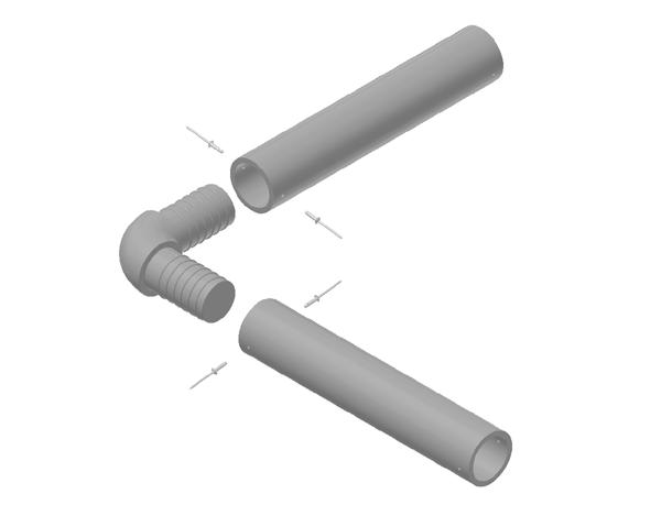
3 Installation Instructions 2. For end posts, install the End Post Kit (PN ) or for interior posts, the Post to Kit (PN ) to each post. When installing the End Post Kit, countersink the hole where the head of the flat head bold will be located so that it is flush. When installing the 1/4" diameter bolt in either connecter kit, torque the lock nut until it holds the Saddle s tightly to the post. After assembly, it will not be possible to retighten these bolts. CROSS SECTIONS OF RAIL TO POST CONNECTIONS END POST CONNECTOR KIT PN# POST TO MID-RAIL CONNECTOR KIT PN# POST TO TOP RAIL CONNECTOR KIT PN# Beginning at one end of the guardrail installation, measure the center to center distance between the first and second post. Cut the mid-rail from 1.9 OD Round Tube Rail (PN ). The Mid-Rail Length (MRL) is equal to the Post Spacing (PS) minus 3 inches (76.2 mm). GUARDRAIL ELEVATION See Details Guardrail Length (GL) Top Rail Length (TRL) See Details Mid-Rail Length (MRL) = (PS) - 3" [76mm] Post Spacing (PS) PS 4'-0" [1219mm] Max 4. Loosen or remove the second post and install the mid-rail by bonding and riveting it to the saddle connectors on the first and second post. Mix only enough adhesive (PN ) that you can use in 20 minutes. Lightly sand the inside of the 1.9 inch OD Round Tube and the mating surfaces of the saddle connector and remove any dust. Bond the midrail tube to the saddle connectors by applying adhesive to both the inside of the 1.9 inch OD Round Tube and the Saddle and pressing together firmly. Install the two rivets by drilling 1/8 diameter holes as indicated in the details and setting the rivets. Wipe away any excess adhesive. Reinstall and replumb the second post. 5. Repeat this procedure until all mid-rails are installed between the posts in the guardrail run. 6. Cut the top rail from 1.9 inch OD Round Tube (PN ) following the dimensions given in the illustration. Subtract the dimensions listed below from the Guardrail Length (GL) to arrive at the Top Rail Length (TRL). The dimensions are also shown on the End Condition Details on page 6 and 7. a. Reduce length by 2-1/8 inches (54 mm) for each Return, End Post, or 90 Turn Condition. b. Reduce length by 1/8 inch (3 mm) for Stub End Condition
4 Installation Instructions c. Do not reduce length for Non-90 Turn End Condition. Miter end of rail as required to fit adjoining rail section. d. Top Rails longer than 20 ft (6096 mm) may be spliced together using the In-Line Splice Kit (PN ) Splices may be placed anywhere between posts. 7. Dry fit the Saddle s (PN ) provided with the post kits to the top of each post. Dry fit and position the top rail cut in step (6) into the Saddle s and verify IN-LINE SPLICE KIT (PN ) 1.90" O.D. RAIL 10 LG IN-LINE SPLICE 1/8" DIA. S.S. RIVET (4 EA) 1.90" O.D. RAIL that the end of the rail is in the correct location and that it is cut to the correct length. Using masking tape or packing tape, temporarily attach the top rail to the Saddle s without taping them to the posts. This will temporarily position the Saddle s relative to the posts to allow the top rail to be accurately drilled for their attachment. 8. Gently lift the top rail/saddle s from the posts, rotate the top rail 180 degrees and mark the top rail using the Saddle s as a guide. Mark the locations of the holes in the top rail using a permanent marker or pencil through the hole in the Saddle. 9. Remove the Saddle s from the top rail and drill a 3/8 (9.5 mm) diameter hole at each Saddle location. Drill the holes as perpendicular to the top rail as possible. 10. At each Saddle location, install a 1/4 20 UNC rivet nut using the Rivet Nut Installation Tool (PN ). Install rivet nut flush with the surface of the top rail. 11. Attach each Saddle to the top rail using the 1/4 x 1 hex head bolt and flat washer supplied with the post kit. Before installing the bolt, coat the threads with a thread locking compound to prevent loosening. After assembly to the posts, it will not be possible to tighten this bolt. Torque the bolt until the Saddle is firmly held against the top rail. 12. Attach the top rail/saddle assembly to the tops of the posts by bonding and riveting following the instructions given in step 4. If the guardrail run includes an End Post Condition, Install the Fixed 90 Rail Splice (PN ) into the top rail prior to installing the top rail. Follow step 14 for connection to the end post. 13. The end conditions of the rail section can now be installed following steps 14 through 18 and referencing the End Condition Details on pages 6 and 7. POST INSTALLATION METHODS - Not all base conditions shown can be installed using modular guardrail posts. Posts may be fabricated by the installer or a proposal for custom fabricated posts may be obtained from Fibergrate. For installation conditions not shown, contact Fibergrate. All details are for posts spaced 4 max on centers to meet a F.O.S. of 2.0 under OSHA and IBC loads, unless noted otherwise. DRAWING A - POST TO FRP OR STEEL CHANNEL DRAWING B - POST TO STEEL PLATE ON STEEL BEAM BOLT ASSEMBLY CHANNEL BOLT ASSEMBLY STEEL BEAM STEEL PLATE
5 Post Installation Details POST INSTALLATION METHODS CONT. - For installation conditions not shown, contact Fibergrate. All details are for posts spaced 4 max on centers to meet a F.O.S. of 2.0 under OSHA and IBC loads, unless noted otherwise. DRAWING C - POST TO FRP OR STEEL BEAM OR CHANNEL WITH FRP SPACERS DRAWING D - POST TO STEEL ANGLE ON FRP OR STEEL BEAM BOLT ASSEMBLY BEAM OR CHANNEL FRP COLLAR WITH 1.9"Ø ROUND TUBE SPACER STEEL 8 1/2" LG. PLATE SOLID BOLT ASSEMBLY STEEL BEAM DRAWING F - SIDE MOUNT POST TO CONCRETE DRAWING E - REMOVABLE POST TO FRP OR STEEL BEAM DRAWING F - SIDE MOUNT POST TO CONCRETE 8 1/2" LG. SOLID BOLT ASSEMBLY BEAM OR CHANNEL 1 3/4"x1/4" SQUARE TUBE SPACERS 6"x6"x5/8" THICK FRP PLATE DRAWING G - REMOVABLE EMBEDDED POST IN CONCRETE TOP OF CONCRETE 3 13/16" 1/2"Ø ADHESIVE ANCHOR DRAWING H - FIXED EMBEDDED POST IN CONCRETE DRAWING G - REMOVABLE EMBEDDED POST IN CONCRETE 11 1/4" LG. SOLID 6" LG. 1.9"Ø SLEEVE EMBEDDED IN CONCRETE DRAWING H - FIXED EMBEDDED POST IN CONCRETE DRAWING I - TOP MOUNTED STAINLESS STEEL STANCHION BASE 6" EMBEDMENT 3"Ø x 1/4" THICK PLATE DRAWING J - TOP MOUNTED FRP STANCHION BASE 6" EMBEDMENT 3/4"Ø x 2 3/4" LG. ROD DRAWING I - TOP MOUNTED STAINLESS STEEL STANCHION BASE 316 S.S. STANCHION BASE 1/2"Ø ADHESIVE ANCHOR 1.90"Ø ROUND 8 1/2" LG. SOLID 1/2"Ø 316 S.S. BOLT ASSEMBLY DRAWING J - TOP MOUNTED FRP STANCHION BASE 1/2"Ø ADHESIVE ANCHOR 4"x6"x3/4" THICK FRP BASE PLATE 10" POURED POST ROUND TUBE SPACER 2 1/8" 4" 2 1/8" 2 3/8" 2 1/2" 4"
6 Installation Instructions 14. End Post Condition: Add a 1/4 inch (6.4 mm) long spacer cut from the 1.9 OD Round Tube Rail (PN ) to fit between the Fixed 90 Rail Splice (PN ) and the top of the end post. The connection between the Fixed 90 Rail Splice and the top rail and post are otherwise identical to the procedure described in step Turn End Condition (Max 18 inches/457 mm from Post): Connect the ends of the top and mid rail to the adjoining guardrail section using the Fixed 90 Rail Splice Kit (PN ). The mid rail is cut to the 90 Turn Length minus 2-11/16 inches (68mm). The connection between the Fixed 90 Rail Splices and the two rails are identical to the procedure described in step Non-90 Turn End Condition (Max 18 inches/457 mm from Post): Connect the ends of the top and mid rail to the adjoining guardrail section using the Adjustable Rail Splice Kit (PN ). The mid rail is cut to the Non-90 Turn Length minus 1-1/2 inches (38mm) and the end is miter cut to fit the adjoining rail section. The connection between the Adjustable Rail Splices and the two rails are identical to the procedure described in step Return End Condition (Max 18 inches/457 mm from Post): Cut a 17-5/8 inch (448 mm) length of 1.9 OD Round Tube Rail (PN ) to act as the vertical portion of the return. The mid rail is cut to the Return Length minus 18. Stub End Condition (Max 12 inches/305 mm from Post): Bond and rivet an End Cap (PN ) into the open end of the top and mid rails. The length of the mid rail is the Stub Length minus 1-5/8 inches (41mm). The connections are made using the procedure described in step Kickplate: Cut to length and align Kickplate (PN ) 1/4 inch (6mm) above the walking surface. Drill 3/16 inch (4.75 mm) diameter holes through the center of the kickplate at posts. Attach the kickplate to the post using 1/4 inch x 1 inch self-tapping screws. Be careful not to over torque the self-tapping screws and strip the holes. 20. Kickplate Splices: Drill kickplate for Kickplate Splice Kit (PN ) and 90 Kickplate Splice Kit (PN ) using 5/16-inch (8 mm) drill bits for installation of the 1/4 Inch diameter bolts supplied with the kits. END CONDITION DETAILS END POST CONNECTION DETAIL 90 TURN END CONDITION Fixed 90 Rail Splice 1/4" [6mm] SPACER 2 1/8" [54mm] Top Rail 2 1/8" [54mm] Post to Top Rail End Post [38mm] Fixed 90 Rail Splice at 90 Turn (MR90T) =(90TL) - 3 5/8" [92MM] MR90T 1'-6" Max [457mm Max] 6 90 Turn Length (90TL)
7 Installation Details NON 90 TURN END CONDITION NON 90 TURN END CONDITION RETURN RETURN DETAIL END CONNECTION PLAN VIEW Adjustable Rail Splice 2 1/8" [54mm] Post to Top Rail ELEVATION 0" [0mm] [38mm] Post to Top Rail 1'-5 5/8" [447mm] [38mm] at Non 90 Turn (MRN90T) =(N90TL) - [38MM] Non 90 Turn Length (N90TL) MRN90T 1'-6" Max [457mm Max] Fixed 90 Rail Splice at Return (MRR) =(RL) - 3 5/8" [92MM] Return Length (RL) MRR 1'-6" Max [457mm Max] STUB END CONDITION 1/8" [3mm] Post to Top Rail End Cap [38mm] KICKPLATE SPLICE End Cap at Stub (MRS) =(SL) - 1 5/8" [41MM] Stub Length (SL) MRS 1'-0" Max [305mm Max] Post 90 Splice Angle 90 Splice Angle Kickplate Splice Plate 1/4 Bolt Assemblies (2 Per Splice Typ)


8 Fibergrate Products & Services Fibergrate Molded Grating Fibergrate molded gratings are designed to provide the ultimate in reliable performance, even in the most demanding conditions. Fibergrate offers the widest selection in the market with multiple resins and more than twenty grating configurations available in many panel sizes and surfaces. Safe-T-Span Pultruded Industrial and Pedestrian Gratings Combining corrosion resistance, long-life and low maintenance, Safe-T-Span provides unidirectional strength for industrial and pedestrian pultruded grating applications Fibergrate Composite Structures Inc. believes the information contained here to be true and accurate. Fibergrate makes no warranty, expressed or implied, based on this literature and assumes no responsibility for the consequential or incidental damages in the use of these products and systems described, including any warranty of merchantability or fitness. Information contained here can be for evaluation only. The marks and trade names appearing herein, whether registered or unregistered, are the property of Fibergrate Composite Structures Inc. Fibergrate Inc Part No / Printed in the USA Dynaform Structural Shapes Fibergrate offers a wide range of standard Dynaform pultruded structural profiles for industrial and commercial use, including I-beams, wide flange beams, round and square tubes, bars, rods, channels, leg angles and plate. Dynarail & DynaRound Guardrail, Handrail & Ladders Easily assembled from durable components or engineered and prefabricated to your specifications, Dynarail square tube and DynaRound round tube railing systems and Dynarail safety ladder systems meet or exceed OSHA and strict building code requirements for safety and design. Custom Composite Solutions Combining Fibergrate s design, manufacturing and fabrication services allows Fibergrate to offer custom composite solutions to meet our client s specific requirements. Either through unique pultruded profiles or custom open molding, Fibergrate can help bring your vision to reality. Design & Fabrication Services Combining engineering expertise with an understanding of fiberglass applications, Fibergrate provides turnkey design and fabrication of fiberglass structures, including platforms, catwalks, stairways, railings and equipment support structures. Worldwide Sales & Distribution Network Whether a customer requires a platform in a mine in South Africa to grating on an oil rig in the North Sea, or walkways in a Wisconsin cheese plant to railing at a water treatment facility in Brazil; Fibergrate has sales and service locations throughout the world to meet the needs and exceed the expectations of any customer. [ ] SAFE Heavy Metal Arsenic Barium Cadmium Chromium Lead Mercury Nickel Selenium Silver ISO QUALITY CERTIFIED F A C I L I T I E S Fax: info@fibergrate.com
HANDRAIL HEIGHT PER LOCAL CODE AUTHORITY
 WITH OPTIONAL S.S. S PLEASE READ PLEASE READ THESE INSTRUCTIONS THOROUGHLY PRIOR TO BEGINNING THE INSTALLATION! THIS INSTRUCTION SHEET IS INTENDED TO PROVIDE A SPECIFIC GUIDE TO FOLLOW FOR THE INSTALLATION
CONTENTS TOOL LIST U P S I D E I N N O V A T I O N S, L L C RAMP AND STEP SYSTEM ASSEMBLY INSTRUCTIONS. Revised: June 2013
 U P S I D E I N N O V A T I O N S, L L C RAMP AND STEP SYSTEM ASSEMBLY INSTRUCTIONS TOOL LIST Required Tools: - Reciprocating Saw with Metal Cutting Blade - Drill - 7/16 Drill Bit for Metal Drilling -
NX8 SERIES 6-1/4 HANDRAIL W/ VINYL HANDGRIP
 6-1/4 HANDRAIL W/ VINYL HANDGRIP TYPICAL ASSEMBLY 5 2 BUTT JOINT 12 10 9 1 8 11 6 3 7 4 BUTT JOINT COMPONENT LIST 1 LEFT RETURN 7 UPPER IMPACT ABSORBER 2 RIGHT RETURN 8 LOWER IMPACT ABSORBER 3 OUTSIDE
MX8 SERIES 6-1/4 HANDRAIL W/ VINYL HANDGRIP
 6-1/4 HANDRAIL W/ VINYL HANDGRIP TYPICAL ASSEMBLY 5 2 BUTT JOINT 12 10 9 1 8 11 6 3 7 4 BUTT JOINT COMPONENT LIST 1 LEFT RETURN 7 UPPER IMPACT ABSORBER 2 RIGHT RETURN 8 LOWER IMPACT ABSORBER 3 OUTSIDE
1. TOOLS + MATERIALS REQUIRED
 R INSTALLATION INSTRUCTIONS PRODUCT: BALDUR + ODEN CONFIGURATION: BI-PARTING DOOR MOUNT: TOP MOUNT Product is covered by U.S. patents. For more information visit www.krownlab.com. TOOLS + MATERIALS REQUIRED
HANDRAIL HEIGHT PER LOCAL CODE AUTHORITY. 6 3/8" [161.9mm]
![HANDRAIL HEIGHT PER LOCAL CODE AUTHORITY. 6 3/8 [161.9mm]](/thumbs/74/70647988.jpg "HANDRAIL HEIGHT PER LOCAL CODE AUTHORITY. 6 3/8 [161.9mm]") PLEASE READ PLEASE READ THESE INSTRUCTIONS THOROUGHLY PRIOR TO BEGINNING THE INSTALLATION! THIS INSTRUCTION SHEET IS INTENDED TO PROVIDE A SPECIFIC GUIDE TO FOLLOW FOR THE INSTALLATION OF THIS. CONTAINED
PLEASE READ PLEASE READ THESE INSTRUCTIONS THOROUGHLY PRIOR TO BEGINNING THE INSTALLATION! THIS INSTRUCTION SHEET IS INTENDED TO PROVIDE A SPECIFIC GUIDE TO FOLLOW FOR THE INSTALLATION OF THIS. CONTAINED
PRODUCT: LOKI INSTALLATION INSTRUCTIONS. Product is covered by U.S. patents. For more information visit
 R INSTALLATION INSTRUCTIONS PRODUCT: LOKI CONFIGURATION: SINGLE DOOR MOUNT: GLASS MOUNT Product is covered by U.S. patents. For more information visit www.krownlab.com . TOOLS + MATERIALS REQUIRED TOOLS
Installation Instructions for. Handrail Component System
 Handrail STEP-BY-STEP Installation Instructions for Handrail Component System Rise in Inches Run in Inches 8 8.5 9 9.5 10 10.5 11 11.5 12 12.5 13 13.5 14 14.5 15 8.5 47 45 43 42 40 39 38 36 35 34 33 32
Installation Instruction
 Tools Needed for Assembly Stud finder (for wood stud wall) Pencil Mark Electric drill Wood Stud Wall Installation Step 1. Locate the Wood Studs Installation Instruction Drill bit (for wood stud wall) Masonry
TREX PERGOLA INSTALLATION INSTRUCTIONS
 RECOMMENDED TOOLS/SUPPLIES: Pencil 4' Level Measuring Tape Framing Square/Speed Square 8' High Step Ladder (Two recommended) Hacksaw or Bolt Cutters Socket Wrench with 9/16" Socket and 3/4" Deep Socket
Installation Instructions for. Before You Begin TOOLS REQUIRED
 Composite Railing System STEP-BY-STEP Installation Instructions for Spectrum Composite Railing Virtually maintenance free 20-year warranty EverNew Spectrum Railing system is designed to work with a number
HANDRAIL HEIGHT PER LOCAL CODE AUTHORITY. 6 3/8" [161.9mm]
![HANDRAIL HEIGHT PER LOCAL CODE AUTHORITY. 6 3/8 [161.9mm]](/thumbs/79/79002604.jpg "HANDRAIL HEIGHT PER LOCAL CODE AUTHORITY. 6 3/8 [161.9mm]") PLEASE READ PLEASE READ THESE INSTRUCTIONS THOROUGHLY PRIOR TO BEGINNING THE P-RSAN-INT INSTALLATION! THIS INSTRUCTION SHEET IS INTENDED TO PROVIDE A SPECIFIC GUIDE TO FOLLOW FOR THE INSTALLATION OF THIS
PLEASE READ PLEASE READ THESE INSTRUCTIONS THOROUGHLY PRIOR TO BEGINNING THE P-RSAN-INT INSTALLATION! THIS INSTRUCTION SHEET IS INTENDED TO PROVIDE A SPECIFIC GUIDE TO FOLLOW FOR THE INSTALLATION OF THIS
Downtown Rack. Custom logo option available
 Custom logo option available Downtown Rack The Downtown Rack uses thick, square-tube construction that can t be cut with a pipe cutter. The extended width of the Downtown Rack makes for easy bike parking
Swerve Rack CUSTOM RACKS AVAILABLE
 CUSTOM RACKS AVAILABLE Swerve Rack The design of the Swerve mirrors the bike frame, thus providing superior bike support while making it easy to secure both the bike frame and wheel with a standard u-lock.
PORCH-LOC INSTALLATION INSTRUCTIONS
 PORCH-LOC INSTALLATION INSTRUCTIONS 2017 HB&G Building Products, Inc. Porch-Loc Installation Instructions NOTE: DISCARD THE INSTALLATION INSTRUCTIONS AND HARDWARE THAT CAME IN YOUR PERMAPOST PACKAGING
Tuf-Lite and Tuf-Lite II Fans 4000 Series Hub
 Tuf-Lite and Tuf-Lite II Fans 4000 Series Hub INSTALLATION MANUAL Hudson Tuf-Lite and Tuf-Lite II fan blades Adjustable Pitch Fan Assembly 15 thru 20 Diameter Hudson Tuf-Lite (black) fan blades are made
THE ROGUE TM FUNSLIDE TM
 THE ROGUE TM FUNSLIDE TM ASSEMBLY AND INSTALLATION INSTRUCTIONS * * C A U T I O N * * S.R. SMITH ROGUE TM FUNSLIDES TM ARE MANUFACTURED FOR INSTALLATION AND USE ON RESIDENTIAL INGROUND POOLS ONLY. ROGUE
INSTALLATION INSTRUCTIONS FOR FRONT CASTING DECK RAIL Ranger
 INSTALLATION INSTRUCTIONS FOR FRONT CASTING DECK RAIL Ranger TOOLS REQUIRED FOR INSTALLATION: Drill motor, (1) 5/16 inch drill bit, (1) 13/64 drill bit, (1) 3/16 inch hex wrench (1) 3/32 inch hex wrench.
INSTALLATION SUGGESTIONS LEVEL APPLICATION LIMITED WARRANTY
 INSTALLATION SUGGESTIONS LEVEL APPLICATION LIMITED WARRANTY L.J. Smith, Inc. issues the following Limited Warranty: The product(s) furnished hereunder are warranted to be free from defects in material
Tuf-Lite III Fans K Hi Temp 3000KHT Series Hub
 Tuf-Lite III Fans K Hi Temp 3000KHT Series Hub INSTALLATION MANUAL Adjustable Pitch Fan Assembly 11 thru 15 Diameter Hudson Tuf-Lite III fan blades Hudson Tuf-Lite III Hi Temp (Red) fan blades are of single
1. VERIFY ALL COMPONENTS
 R INSTALLATION INSTRUCTIONS RAGNAR+ODEN FACE MOUNT, BYPASSING. VERIFY ALL COMPONENTS BASE KIT Track stand-offs Front trolley kit * Rear trolley kit * Allen keys Track fastener kit - wood - Bottom guide
ASSEMBLY AND INSTALLATION INSTRUCTIONS
 ASSEMBLY AND INSTALLATION INSTRUCTIONS CORPORATE HEADQUARTERS WESTERN SALES AND MANUFACTURING PLANT P.O. Box 400 1017 SW Berg Parkway Canby, Oregon 97013 (503) 266 2231 (503) 266 4334 www.srsmith.com 06
Fiberglass Pultruded. SI Units. Building the World to Last HIGH PERFORMANCE COMPOSITE SOLUTIONS
 CELEBRATING 50YEARS Fiberglass Pultruded SI Units HIGH PERFORMANCE COMPOSITE SOLUTIONS Building the World to Last Pultruded Products Introduction Combining corrosion resistance, long life and a low maintenance
KNEEWALL APPLICATION
 INSTALLATION SUGGESTIONS KNEEWALL APPLICATION LIMITED WARRANTY L.J. Smith, Inc. issues the following Limited Warranty: The product(s) furnished hereunder are warranted to be free from defects in material
Fortress Fe Posts must always be secured to the deck framing. Fortress Fe Posts should never be attached to only the deck boards.
 Installation Instructions for Fortress Horizontal Cable Panel System with UB-05 Brackets and Fe Posts It is the responsibility of the installer to meet all code and safety requirements, and to obtain all
Tuf-Lite III Fans 5000K Series Hub
 Tuf-Lite III Fans 5000K Series Hub INSTALLATION MANUAL Hudson Tuf-Lite III fan blades Adjustable Pitch Fan Assembly 20 thru 30 Diameter Hudson Tuf-Lite III fan blades are of single piece fiberglass reinforced
Tuf-Lite III Fans 3000K Series Hub
 Tuf-Lite III Fans 3000K Series Hub INSTALLATION MANUAL Adjustable Pitch Fan Assembly 11 thru 15 Diameter Hudson Tuf-Lite III fan blades Hudson Tuf-Lite III fan blades are of single piece fiberglass reinforced
HANDRAIL HEIGHT PER LOCAL CODE AUTHORITY. 6 3/8" [161.9mm]
![HANDRAIL HEIGHT PER LOCAL CODE AUTHORITY. 6 3/8 [161.9mm]](/thumbs/76/73680161.jpg "HANDRAIL HEIGHT PER LOCAL CODE AUTHORITY. 6 3/8 [161.9mm]") P-RSS PLEASE READ PLEASE READ THESE INSTRUCTIONS THOROUGHLY PRIOR TO BEGINNING THE P-RSS INSTALLATION! THIS INSTRUCTION SHEET IS INTENDED TO PROVIDE A SPECIFIC GUIDE TO FOLLOW FOR THE INSTALLATION OF THIS
P-RSS PLEASE READ PLEASE READ THESE INSTRUCTIONS THOROUGHLY PRIOR TO BEGINNING THE P-RSS INSTALLATION! THIS INSTRUCTION SHEET IS INTENDED TO PROVIDE A SPECIFIC GUIDE TO FOLLOW FOR THE INSTALLATION OF THIS
Tuf-Lite and Tuf-Lite II Fans 4000 Series Hub
 Tuf-Lite and Tuf-Lite II Fans 4000 Series Hub INSTALLATION MANUAL Hudson Tuf-Lite and Tuf-Lite II fan blades Adjustable Pitch Fan Assembly 15 thru 20 Diameter Hudson Tuf-Lite (black) fan blades are made
PRODUCT: BALDUR + ODEN
 R INSTALLATION INSTRUCTIONS PRODUCT: BALDUR + ODEN CONFIGURATION: SINGLE DOOR MOUNT: GLASS MOUNT Product is covered by U.S. patents. For more information visit www.krownlab.com . TOOLS + MATERIALS REQUIRED
Horizontal Cable Systems
 ALUMINUM RAILING INSTALLATION INSTRUCTIONS Horizontal Cable Systems 1) Check Contents Of Packages: Verify that all parts have arrived and that they match the packing list. 1A) Coastal applications: Confirm
Tuf-Lite III Fans 5000K Series Hub
 Tuf-Lite III Fans 5000K Series Hub INSTALLATION MANUAL Hudson Tuf-Lite III fan blades Adjustable Pitch Fan Assembly 20 thru 30 Diameter Hudson Tuf-Lite III fan blades are of single piece fiberglass reinforced
Full Height Ladder Safety Gate
 Full Height Ladder Safety Gate Installation Instructions/Operation and Maintenance Manual Models Powder Coat Yellow (PCY) 304 Stainless Steel (SS) Hot Dipped Galvanized (GAL) Table of Contents Product
Tuf-Lite II Fans H Hi Temp 3000HT Series Hub
 Tuf-Lite II Fans H Hi Temp 3000HT Series Hub INSTALLATION MANUAL Hudson Tuf-Lite II Hi Temp Fan Blades Adjustable Pitch Fan Assembly 5 through 14 Diameter Hudson Tuf-Lite II Hi Temp fan blades (Red) are
The following instructions will guide you through the installation of your new vinyl railing stair kit.
 Installation Guide Vinyl Standard Stair Railing Tools Required Protective eye glasses Tape measure Variable speed drill/screwdriver Rotary hammer or hammer drill and masonry percussion bit recommended
HANDRAIL HEIGHT PER LOCAL CODE AUTORITY
 WOOD END CAPS PLEASE READ PLEASE READ THESE INSTRUCTIONS THOROUGHLY PRIOR TO BEGINNING THE HRWS-6CSLBW INSTALLATION! 3 1/16" [77.7mm] THIS INSTRUCTION SHEET IS INTENDED TO PROVIDE A SPECIFIC GUIDE TO FOLLOW
THE CASCADE & SLINGER FUNSLIDES
 THE CASCADE & SLINGER FUNSLIDES ASSEMBLY AND INSTALLATION INSTRUCTIONS * * C A U T I O N * * S.R. SMITH CASCADE TM & SLINGER TM FUNSLIDES TM ARE MANUFACTURED FOR INSTALLATION AND USE ON RESIDENTIAL INGROUND
Fortress Fe Posts must always be secured to the deck framing. Fortress Fe Posts should never be attached to only the deck boards.
 Installation Instructions for FortressCable H-Series Stair Panels with Simplified Stair Bracket SSB-05 and Fe Posts It is the responsibility of the installer to meet all code and safety requirements, and
THE ROGUE TM GRAND RAPIDS TM ASSEMBLY AND INSTALLATION INSTRUCTIONS
 THE ROGUE TM GRAND RAPIDS TM ASSEMBLY AND INSTALLATION INSTRUCTIONS CORPORATE HEADQUARTERS WESTERN SALES AND MANUFACTURING PLANT P.O. Box 400 1017 SW Berg Parkway Canby, Oregon 97013 (503) 266-2231 (503)
HANDRAIL HEIGHT PER LOCAL CODE AUTORITY
 WITH WOOD END CAPS PLEASE READ PLEASE READ THESE INSTRUCTIONS THOROUGHLY PRIOR TO BEGINNING THE INSTALLATION! 3" [77.3mm] THIS INSTRUCTION SHEET IS INTENDED TO PROVIDE A SPECIFIC GUIDE TO FOLLOW FOR THE
GlideRite Retractable Cover System For Hot Spot Spas (SE & SLX only)
") List of Contents Quantity Description 12 #10 x 1 ½ Flat Head Phillips Screw (see pg. 2) 2 #10 x ½ Pan Head Phillips Screw (see pg. 2) 8 ¼ x 2 ½ Lag Bolt (see pg. 2) 7 ¼ 20 x 5 / 8 Hex Head Bolt (see pg.
List of Contents Quantity Description 12 #10 x 1 ½ Flat Head Phillips Screw (see pg. 2) 2 #10 x ½ Pan Head Phillips Screw (see pg. 2) 8 ¼ x 2 ½ Lag Bolt (see pg. 2) 7 ¼ 20 x 5 / 8 Hex Head Bolt (see pg.
Installation Instructions/Operation and Maintenance Manual. PS DOORS Contact Information. Website psdoors.com
 Ladder Safety Gate Installation Instructions/Operation and Maintenance Manual Models All Models: LSG-5 to LSG-48 Table of Contents Product Information...2 Inspection & Mainteance...2 Warranty Information...2
Tuf-Lite II Fans 3000H Series Hub
 Tuf-Lite II Fans 3000H Series Hub INSTALLATION MANUAL Adjustable Pitch Fan Assembly 5 through 14 Diameter Hudson Tuf-Lite II Fan Blades Hudson Tuf-Lite II (white, prev. Blue**) are made from fiberglass
Pickup Box Utility Rack Package Installation (Instruction ID: )
") 017 Chevrolet Colorado Pickup - WD (VIN S) Canyon, Colorado Accessory Installation Manual N America Document ID: 3966961 Pickup Box Utility Rack Package Installation (Instruction ID:3144879) Installation
017 Chevrolet Colorado Pickup - WD (VIN S) Canyon, Colorado Accessory Installation Manual N America Document ID: 3966961 Pickup Box Utility Rack Package Installation (Instruction ID:3144879) Installation
GlideRite Retractable Cover System For HotSpring & Tiger River Spas (except Classic & pre-2000 Landmark Spas)
") List of Contents Quantity Description 12 #10 x 1 ½ Flat Head Phillips Screw (see pg. 2) 2 #10 x ½ Pan Head Phillips Screw (see pg. 2) 8 ¼ x 2 ½ Lag Bolt (see pg. 2) 7 ¼ 20 x 5 / 8 Hex Head Bolt (see pg.
List of Contents Quantity Description 12 #10 x 1 ½ Flat Head Phillips Screw (see pg. 2) 2 #10 x ½ Pan Head Phillips Screw (see pg. 2) 8 ¼ x 2 ½ Lag Bolt (see pg. 2) 7 ¼ 20 x 5 / 8 Hex Head Bolt (see pg.
Tuf-Lite II Fans 3000HC Series Hub
 Tuf-Lite II Fans 3000HC Series Hub INSTALLATION MANUAL Hudson Tuf-Lite II fan blades Adjustable Pitch Fan Assembly 8 through 10 Diameter Hudson Tuf-Lite II (White) are made from fiberglass reinforced vinyl-ester
INSTALLATION INSTRUCTIONS
 ECLIPSE CANOPY INSTALLATION INSTRUCTIONS IMPORTANT NOTE: ENSURE ALL RELEVANT PERSONNEL READ THE POINTS LISTED WITHIN THIS LEAFLET AND THAT A COPY IS GIVEN TO STAFF INVOLVED WITH THE INSTALLATION AND MAINTENANCE
Loading Dock Safety Gate
 Installation Instructions/Operation and Maintenance Manual Models LDSG-120-PCY LDSG-144-PCY Table of Contents Product Information...2 Parts List...3 Installation Instructions...5 Operation...13 Inspection
Installation Instructions
 Column & Beam Units with Debris Netting Installation Instructions Laminated Wood Systems, Inc. Seward, Nebraska 800-949-3526 2015 LWS, INC. AVR-NET INSTALL 05-12-16 AVR Installation Notes 1 Safety The
KOLO SHELTER Installation Instructions Parts List
 Parts List Roof Cap Rafter Upright Polycarbonate Polycarbonate Drop Polycarbonate Flange Center Weldment (Short length shown above) Polycarbonate Edge Bolt.25 x 6.5 Bolt.625 x 7.5 Threaded Rod.75 x 14
Now available at participating Feeney (2/14) AF# A. Stores. 1/8'' Stainless Steel Cable Assemblies to Enhance Any Railing and Any View!
 AF# A. Stores. 1/8'' Stainless Steel Cable Assemblies to Enhance Any Railing and Any View!") 2014 Feeney (2/14) AF# 2009-236A Now available at participating Stores 1/8'' Stainless Steel Cable Assemblies to Enhance Any Railing and Any View! Easy-to-install, prefabricated cable assemblies are an
2014 Feeney (2/14) AF# 2009-236A Now available at participating Stores 1/8'' Stainless Steel Cable Assemblies to Enhance Any Railing and Any View! Easy-to-install, prefabricated cable assemblies are an
Horizontal Cable Systems
 ALUMINUM RAILING INSTALLATION INSTRUCTIONS v2012 orizontal Cable Systems 1) Check Contents Of Packages: Verify that all parts have arrived and that they match the packing list. 1A) Coastal applications:
PREPARATION & TOOL CHECKLIST
 INSTRUCTION MANUAL RAILING PRODUCTS BEGIN TO AGE AS SOON AS THEY ARE EXPOSED TO NATURE. BUILDINGS EXPERIENCE AGING FACTORS DIFFERENTLY, SO IT IS DIFFICULT TO PREDICT HOW LONG RAILING PRODUCTS WILL LAST.
FIXED PANEL SLIDER QCI5241
 INSTALLATION INSTRUCTIONS FIXED PANEL SLIDER QCI5241 FRAMELESS PANEL / DOOR / PANEL FRAMELESS DOOR / PANEL QCI5241 REV. 0 Page 1 Certified 06/16/2016 Parts List *Quantities may vary QCI5241 REV. 0 Page
PRO CYC PRO CYC, INC. SYSTEM SUPER 1.5QS
 Assembly Instructions System Super 1.5QS Congratulations on your decision to use the world s most advanced and user-friendly cyclorama system. We have taken a great deal of care to create and ship your
TO O L K IT. Public Bike Repair
 TO O L K IT Public Bike Repair The Dero Tool Kit includes all the necessary tools to perform most routine maintenance and adjustments on most bikes. All the tools are securely fastened with stainless steel
INSTALLATION GUIDE. 5" Balustrade System
 5" Balustrade System PARTS LIST ITEM QTY A PORCH POST INSTALLATION KIT (PPK6) (SEE STEP 3C) 5 1/2" x 5 1/2" Trim Collar 2 2" Wide x 1 1/2" x 2" Angle Bracket 4 MATERIALS NEEDED INSTALLATION GUIDE #14 x
LOFT DOOR HANGER BARN DOORS & HARDWARE. Hardware Installation Instructions. Page
 LOFT DOOR HANGER Page 1 Specifications 2 7/16" 3/8" 1-1/2 1-3/4 Ø3 3 7/8" 11-1/16 Page 2 Parts and Tools Tools Needed Tape Measure Pencil Drill with 1/8, 1/4 and 3/8 bits, 1 spade bit and Phillips bit
Tuf-Lite II Fans 3000H Series Hub
 Tuf-Lite II Fans 3000H Series Hub INSTALLATION MANUAL Adjustable Pitch Fan Assembly 5 through 14 Diameter Hudson Tuf-Lite II Fan Blades Hudson Tuf-Lite II (white, prev. blue**) fan blades are made from
HOUSE PARTS PACKED IN HOUSE BOX PARTS IN PLASTIC BAG (HARDWARE) PARTS IN SMALL PLASTIC BAG (FLOOR CLIPS) PARTS PACKED IN BUNDLE
 PARTS IN SMALL PLASTIC BAG (FLOOR CLIPS) PARTS PACKED IN BUNDLE") Check parts against this list before starting assembly. Refer to illustrations on pages 6 and 7 to view house parts. If any shortages are found, refer to Packing Slip for claim instructions. Item 3 5 6
Check parts against this list before starting assembly. Refer to illustrations on pages 6 and 7 to view house parts. If any shortages are found, refer to Packing Slip for claim instructions. Item 3 5 6
The following instructions will guide you through the installation of your new vinyl railing.
 Installation Guide St. James Vinyl T-Rail Tools Required Protective eye glasses 3/8 x 3 Concrete Anchors/Fasteners (for Tape measure concrete installations) Variable speed drill/screwdriver Philips Driver
Fortress Fe Posts must always be secured to the deck framing. Fortress Fe Posts should never be attached to only the deck boards.
 Installation Instructions for FortressCable H-Series Cable Panel System With UB-05 Brackets and Fe Posts It is the responsibility of the installer to meet all code and safety requirements, and to obtain
PLEASE READ INSTRUCTIONS THOROUGHLY BEFORE PROCEEDING
 Part No. 8870 -or Part No. 9100-9110 Front Fender Flares Flat Panel Design 07-09 Jeep JK, 2/4 Dr. PLEASE READ INSTRUCTIONS THOROUGHLY BEFORE PROCEEDING We have provided complete instructions and specific
ALUMINUM PIPE GUIDERAIL 01/01/
 NOTES PIPE RAILING & POSTS: Structural Tube, Pipe and Bar shall be in accordance with ASTM B22 or ASTM B429, Alloy 606-T6. End Rail 90 bends and corner bends with maximum 4-0" post spacing, may be Alloy
STEEL PIPE GUIDERAIL 01/01/
 NOTES PIPE RAILING & POSTS: Pipe Rails and s shall be in accordance with ASTM A5 Grade B for standard weight pipe and ASTM A500 Grade B, C or D or ASTM A50 for structural tube. Bars for handrail supports
installation guide 1 GUIDE#: pwb-assault-004
 assault WAKEBOARD tower installation guide INSTALLATION SUPPORT 1 important information This Aerial wakeboard tower fits motor boats with 76-108 inch wide beam widths. This measurement is taken from the
Single and Double Gates Operation & Maintenance Manual
 R E L I A B L E S A F E A C C E S S Single and Double Gates Operation & Maintenance Manual 2 System Overview SAFETY GATES KEE GATE is a complete range of safety gates designed specifically to provide permanent
3" [76.0mm] HANDRAIL HEIGHT PER LOCAL CODE AUTHORITY
![3 [76.0mm] HANDRAIL HEIGHT PER LOCAL CODE AUTHORITY](/thumbs/79/78825086.jpg "3 [76.0mm] HANDRAIL HEIGHT PER LOCAL CODE AUTHORITY") WITH OPTIONAL S.S. S PLEASE READ PLEASE READ THESE INSTRUCTIONS THOROUGHLY PRIOR TO BEGINNING THE INSTALLATION! THIS INSTRUCTION SHEET IS INTENDED TO PROVIDE A SPECIFIC GUIDE TO FOLLOW FOR THE INSTALLATION
WITH OPTIONAL S.S. S PLEASE READ PLEASE READ THESE INSTRUCTIONS THOROUGHLY PRIOR TO BEGINNING THE INSTALLATION! THIS INSTRUCTION SHEET IS INTENDED TO PROVIDE A SPECIFIC GUIDE TO FOLLOW FOR THE INSTALLATION
Two Panel Frameless Bypass Door
 INSTALLATION INSTRUCTIONS Two Frameless Bypass Door Series 00 Please Record Model Number From Carton Label Here Please read these instructions carefully to familiarize yourself with the required tools,
Frameless Inline Door With Return QCI5263
 INSTALLATION INSTRUCTIONS Frameless Inline Door With Return QCI5263 WALL MOUNT HINGES FRAMELESS DOOR / PANEL / RETURN PANEL QCI5263 REV. 0 Page 1 Certified 06/17/2016 Parts List with wall mount hinges
AM500-U Installation Guide
 1321 S. State College Blvd., Fullerton, CA 92831 USA Included Components Maximum Flat Panel Weight: 500 lb. / 226.79 kg. Wall Mount Bracket (Qty 2) Cross Bar 5/16 Flat Washers (Qty 6) Universal Spacers
FIXED SHOWER SCREEN For Wall Mount Hinges QCI5283
 FIXED SHOWER SCREEN For Wall Mount Hinges QCI5283 QCI5283 Page 1 Date Certified: 06/16/2016 Parts List with wall mount clamp ITEM NO. DESCRIPTION QTY. 1 FIXED GLASS PANEL 1 2 WALL MOUNT CLAMP 1 3 U-CHANNEL
FRP GATES MM08 FRP GATES Rev. 3 COMPOSITE SOLUTION PAGE 1
 FRP GATES MM08 08.02.2016 Rev. 3 FRP GATES COMPOSITE SOLUTION PAGE 1 SUMMARY 1. USES AND CHARACTERISTICS... 3 2. EMPLOYMENT FIELDS... 4 3. MATERIALS... 5 3.1 TABLE OF PROFILES AND STRUCTURAL ACCESSORIES...
FRAMELESS DOOR / PANEL WITH WALL MOUNT HINGES QCI5274
 FRAMELESS DOOR / PANEL WITH WALL MOUNT HINGES QCI5274 QCI0274 QCI5274 REV. Rev. 1 0 Page Page 1 1 Date Certified: Certified 06/16/2016 10/01/10 Parts List with wall mount hinges ITEM NO. Part # DESCRIPTION
Gared Pro-S Portable Backstop
 Models: 9616 & 9618 Installation, Operation and Maintenance Instructions Please read all instructions before attempting installation or operation of these units SAVE THESE INSTRUCTIONS FOR FUTURE USE PUBLICATION
FXL-168 FIXED RACK ASSEMBLY INSTRUCTIONS SALES ORDER #
 ZOMEWORKS FXL-168 FIXED RACK ASSEMBLY INSTRUCTIONS SALES ORDER # 1 1011 Sawmill Road NW, PO Box 25805, Albuquerque, NM 87125 USA (505) 242-5354 / (800) 279-6342 / FAX (505) 243-5187 E-mail: zomework@zomeworks.com
Football Goal Posts MODEL SERIES: FGP400 and FGP600 series
 Football Goal Posts MODEL SERIES: FGP400 and FGP600 series Installation and Maintenance Instructions Please read all instructions before attempting installation of these units SAVE THESE INSTRUCTIONS FOR
Salter Industries Spiral Stair
 Salter Industries Spiral Stair The Leader in Spiral Staircases Continuous Sleeve Stair Installation Instructions TOOLS NEEDED: 1. Electric drill with hex chuck and Phillips bit 2. Drill bits 1/8", 1/4",
All Terrain Flares 2014 Chevy Silverado
 Page 1/8 Components: 1. Front Flares (2) 2. Rear Flares (2) Tools required: - Utility knife - #2 Phillips driver - Socket wrench - 13 mm Socket - 6 mm Allen Wrench - T-15 Torx bit - Trim Removal Tool -
INSTALLATION INSTRUCTIONS FRAMELESS CONTINUOUS HINGE SHOWER ENCLOSURE QCI5233
 INSTALLATION INSTRUCTIONS FRAMELESS CONTINUOUS HINGE SHOWER ENCLOSURE QCI5233 QCI5233 Rev 0 Page 1 Certified 06/20/2016 INSTALLATION NOTES: Unpack your unit carefully and inspect for freight damage. Lay
Clearview Railing System Installation Instructions
 Clearview Railing System Installation Instructions Disclaimer: AGS Stainless, Inc. has its Clearview Railing Systems designed by a professional engineer to meet the requirements of the latest national
INSTALLATION INSTRUCTIONS FRAMELESS CONTINUOUS HINGE SHOWER ENCLOSURE QCI5232
 INSTALLATION INSTRUCTIONS FRAMELESS CONTINUOUS HINGE SHOWER ENCLOSURE QCI5232 QCI5232 Rev 0 Page 1 Certified 06/20/2016 INSTALLATION NOTES: Unpack your unit carefully and inspect for freight damage. Lay
Privacy Wall Glass Selections - Polished Edge Slider Door
 Privacy Wall Glass Selections - Polished Edge Slider Door 3/6" HEX BIT PUTTY KNIFE #2 ACR BIT SUCTION CUP HOLDERS DOOR LEAF: Satin Tempered Clear Tempered LOCTITE 425 SIDE LIGHT ETCHED GLASS STYLES: Satin
PREPARATION & TOOL CHECK LIST
 INSTRUCTION MANUAL RAILING PRODUCTS BEGIN TO AGE AS SOON AS THEY ARE EXPOSED TO NATURE. BUILDINGS EXPERIENCE AGING FACTORS DIFFERENTLY, SO IT IS DIFFICULT TO PREDICT HOW LONG RAILING PRODUCTS WILL LAST.
Fortress Fe Posts must always be secured to the deck framing. Fortress Fe Posts should never be attached to only the deck boards.
 Installation Instructions for Fortress Vertical Cable Panel System with Brackets and Fe Posts It is the responsibility of the installer to meet all code and safety requirements, and to obtain all required
THE AquaBlast & RocketRide FUNSLIDES
 THE AquaBlast & RocketRide FUNSLIDES ASSEMBLY AND INSTALLATION INSTRUCTIONS * * C A U T I O N * * S.R. SMITH AquaBlast TM & RocketRide TM FUNSLIDES TM ARE MANUFACTURED FOR INSTALLATION AND USE ON RESIDENTIAL
10. Wing prep and subassembly
 Date Section Objective: Construct and fabricate the sub-assemblies of the wing panel. Required Parts: Wing left 11gal PN104-300, Wing right 1gal PN104-400, Wing left 15 gal option PN104-322, Wing right
New Product Release: October 2014 Boone Racks
 New Product Release: October 2014 Boone Racks Double Fido Fountain Mounting: Surface NOTE: THESE ROUGH-IN DIMENSIONS MAY VARY ½: (13 mm) PLUS OR MINUS NOTE: All dimensions subject to manufacturing variance
ELEGANCE SHOWER DOOR/ENCLOSURE INSTALLATION INSTRUCTIONS. Style A Style B Style C Style D
 ELEGANCE SHOWER DOOR/ENCLOSURE INSTALLATION INSTRUCTIONS IMPORTANT DreamLine reserves the right to alter, modify or redesign products at any time without prior notice. For the latest up-to-date technical
Citabria Pro. Aerobatic Parkflyer. by Joel Dirnberger
 Citabria Pro Aerobatic Parkflyer by Joel Dirnberger Revision C: December 21, 2004 Citabria Pro Building Instructions Length: Wingspan: Wing Area: Flying Weight: Wing Loading: Functions: Specifications:
10x10 Trellis Pergola
 0x0 Trellis Pergola ASSEMBLY GUIDE Ver.-007 Table of Contents PAGE 0x0 Trellis Pergola Introduction & Overview...................................................... Pergola Materials Overview..............................................................
Your order will be shipped with the supports and rail components packaged inside the ramp package. Each accessory package is labeled.
 instructions About Your Order. Your order will be shipped with the supports and rail components packaged inside the ramp package. Each accessory package is labeled. Check the Order Before the Carrier leaves!
300C6 CONTINUOUS HINGE SEMI-FRAMELESS DOOR KIT
 300C6 CONTINUOUS HINGE SEMI-FRAMELESS DOOR KIT LIMITED WARRANTY AND REMEDY Alumax Bath Enclosures warrants to its dealers, customers, and all subsequent purchasers and users, that the products supplied
Barn Door & Hardware Installation Guide
 Barn Door & Hardware Guide INTRODUCTION Thank you for purchasing our hardware. Our barn door and hardware will add a stunning accent to your living environment and maximize its space. This manual covers
UNIT No FRAMELESS PIVOT SHOWER DOOR
 INSTALLATION INSTRUCTIONS UNIT No. 3600 FRAMELESS PIVOT SHOWER DOOR NEED INSTALLATION HELP? Call 1-800-45-BASCO (452-2726) Monday - Friday 8:00 A.M. - 4:30 P.M. Eastern Time QCI0020 Rev. 3 Page 1 of 8
340D & 350D SERIES FRAMELESS BYPASS BATH ENCLOSURES
 INSTALLATION INSTRUCTIONS 340D & 350D SERIES FRAMELESS BYPASS BATH ENCLOSURES 800-643-1514 www.alumaxshowerdoor.com Copyright Alumax Bath Enclosures 2014. All rights reserved. !WARNINGS! INSTALLATION WARNINGS
MAKO EC EXTENDED CABINET
 MAKO EC EXTENDED CABINET INSTALLATION GUIDE VERSION 2.0 TDN 0702-00033 03/0 CORPORATE HEADQUARTERS: RMA (RETURN MATERIAL AUTHORIZATION) RETURN ADDRESS: 522 E. Railroad Street 2405 B Street Long Beach,
CSS Central Mount System
 CSS-20 Installation Manual CSS-20 Safety Notifications Below are the installation instructions for the CSS-20-2 Long Span Beam Mounting System. Please read these safety notifications prior to beginning
INSTALLATION INSTRUCTIONS
 INSTALLATION INSTRUCTIONS Universal Low Profile Tilt Mount Model: U.S. Toll Free: 1-866-752-6271 Outside N. America: 1-503-748-5799 E-mail: ts@planar.com FRANCE Phone: +33 5 6378 3810 E-mail: emeats@planar.com
INSTALLATION INSTRUCTIONS
 CREATING POSITIVE CUSTOMER EXPERIENCES INSTALLATION INSTRUCTIONS PDS-PLUS Universal Projector Mount Model: NORTH AMERICA 3130 East Miraloma Avenue Anaheim, CA 92806 USA USA and Canada Phone: 1.800.368.9700