R Form No MILLENNIUM GONDOLA / WALLCASE ASSEMBLY
|
|
|
- Sophia McCarthy
- 6 years ago
- Views:
Transcription

1 R Form No
2 POST THIS WARNING PAGE IN A CONSPICUOUS PLACE, CLEARLY VISIBLE TO ALL STORE PERSONNEL READ BEFORE ASSEMBLING WARNING FOR YOUR SAFETY Install all shelving units according to installation instructions. Shelving and components should only be installed or rearranged by trained personnel who have read and understand these instructions and warnings. Failure to do so may result in damage to shelving or personal injury. Do not exceed Allowable Load Limits (page A3). Do not use damaged parts. Install and use components only as directed. Do not combine Streater products with non-streater products. Always use BASE FRONTS - they affect the structural integrity of the shelving. Do not hang peg hooks, shelves, or other accessories on fixture side that has no base brackets. Do not hang peg hooks, shelves, or other accessories that extend past the base deck. All components which require trim, such as uprites and base brackets, must be installed with trim pieces. Do not expose any sharp or pointed edges to shoppers or employees. Do not climb or stand on shelving. Provide safe access to all levels of storage & display shelving via ladders, stairways or other means in accordance with applicable OSHA regulations. Do not move assembled unit. Do not rearrange shelves while merchandised. Do not lean heavy items against shelving. A1 SAFETY WARNING R Form No
3 BACK PANEL INFORMATION IMPORTANT! Top of pegboard backs are marked with a paint strip. First row of holes are 7/8"from top edge 42" 54" 60" 37 72" 49 84" 96" Wide = 34 17/32" 4 Wide = 46 17/32" /16" /16" 84" thru 96" are two pieces with splicer channel A2 BACK PANEL INFORMATION RAIL INFORMATION NOTE: Center rails are painted Color 03. ALLOWABLE SHELF LOAD LIMITS top rail 4-position 3-position Shelf Sizes 10" 12" 14" 16" 18" 22" 24" 28" Flat Downslant Downslant Upslope center rail splicer rail bottom rail R Form No
4 UNBALANCED LOAD CALCULATIONS When heavily loading one side of your wall or island shelving, it is important to determine if you are creating an unbalanced load that exceeds the maximum 12,000 inch-pounds. The sample calculation below illustrates how you can determine your unbalanced load in inch-pounds. NOTE: Inch-pounds are a measure of the shelf loads acting at a distance (1/2 shelf depth) from the uprite Find the Unbalanced inch-pounds acting on this uprite # 200# # 200# Assume no shelves on side 1 of Section B SECTION A 300# 200# SECTION B This loading situation may be represented by two separate loading diagrams as shown. 14" 12" 100# 200# 300# 200# Side 1 Side 2 SECTION A 12" 16" Deck load does not contribute to unbalanced load. 300# 5.5" 200# 7.5" Side 1 Side 2 SECTION B 12" 16" A3 LOAD CALCULATIONS 3. NOTE: Shelf depth is divided by 2 because an evenly distributed shelf load is calculated as a total load at center of shelf depth. Shelf load is divided by 2 because a shelf load is supported by two uprites. WALL SECTION UNBALANCED LOAD CALCULATION: The method used to determine the unbalanced inchpounds on a wall section is the same as the method shown for an island section. Simply consider the side without shelves having a load of zero. Subtract the smaller unbalanced load from the larger: NOTE: "# indicates inch-pounds. This is the total unbalanced load acting on the uprite and must never exceed 12,000 inch-pounds per uprite. DO NOT EXCEED 12,000 INCH-POUNDS UNBALANCED LOAD! SECTION A SECT. B (Shelf depth 2) x (Shelf load 2) 6" 7" 6" 8" 6" 8" x x x x x x 100# 2 200# 2 300# 2 200# 2 300# 2 200# 2 SIDE 1 SIDE 2 300"# 700"# 900"# 800"# 900"# 800"# TOTAL (Section A and B) 1000"# 3400"# 3400 inch-pounds inch pounds =1400 inch pounds SPECIAL WARNINGS: EXTENSION UPRITES - PEGBOARD BACK LOADS - The maximum unbalanced load on shelves above the joint on an extension uprite should not exceed 2500 inch-pounds. The loads applied to pegboard back should not exceed 150 lbs. on one side of a section with a standard bottom rail (150 lbs. per side for double backs.) R Form No

5 PART IDENTIFICATION 1 Standard End Standard Cover Left End Bottom Arm Cover Bottom Rail Top Rail Center Rail Back Panel Kick Plate R Form No Standard gondola parts

6 PART IDENTIFICATION 2 Bottom Rail Center Rail Splicer Rail Top Rail R Form No Cross components


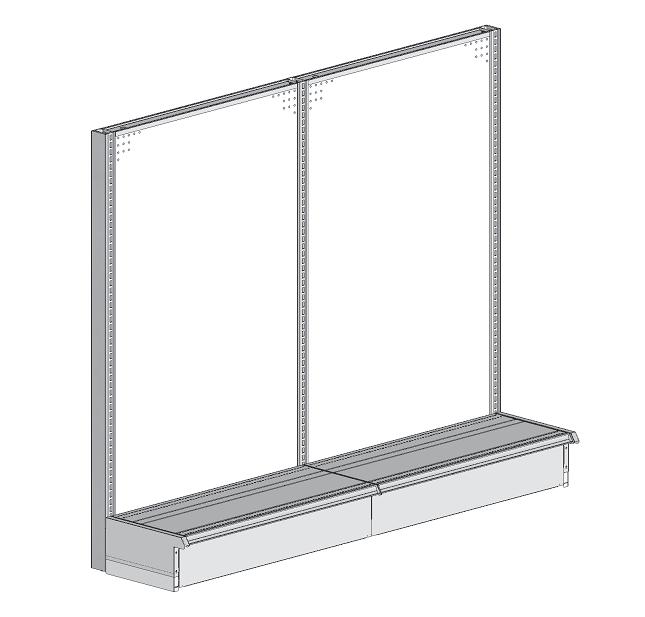
7 1 Snap chalk lines on the floor for locations of island runs. Assemble wallcase the same as the Island and refer to the last page for anchoring instructions. Slide the bottom arm into the slots as pictured 2 below and push down to properly engage the spring loaded locking key. When engaged the tab on the key will be closest to the upright. 3 chalk line Next, install the bottom rail by sliding it into the lowest embossment as pictured to the left. You may need to tap it to properly secure it. Note: With a mallet tap the bottom rail directly over the tab to properly seat it. For wall case and single back installations bend the tab outward to prevent rotation. 3 R Form No Bottom arms, bottom rail


8 4 5 6 Next, install the center rail at mid-height by sliding it into place as pictured to the left and below. You may need to tap the center rail to properly secure it. Note: With a mallet tap the center rail directly over the tab to properly seat it. Install the back panel by inserting it into the channels on the standards slightly above the center rail and slide it down the channels on the standards as shown to the left. When installed the back panel should rest inside the bottom rail channel. Next, assemble remaining framework along chalk line. Do not install the remaining backs yet! FOR SPLIT BACK INSTALLATIONS ONLY! Install the lower back panels first, Then, install the splicer rail to the nearest embossment on the standard. Next, Install the center rail at midlevel of the upper back panels. Last, slide the upper back panels into place as pictured below and to the left. Note: Refer to the back panel information page for detailed information. 4 R Form No Back Panels, center rail
9 A. Leveling procedure important for a proper fit of trim and accessories! leveling wrench LEVELING PROCEDURE Adjust levelers on both base brackets to the same height and make leveler on uprite 1/8" shorter so it does not touch the floor (see side view). Use a screwdriver on the base brackets and the leveling leg wrench on the uprites. Keep the uprites plumb. Check with a carpenters level. Caution: Do not extend base brackets leveling legs more than 1-1/2" 1/8" side view B. string string Anchor a string in corresponding slots in end uprites. Be sure string is taut. Bring corresponding slots on inner uprites to string level by adjusting leveling legs. Caution: Do not extend leveling legs more than 1-1/2" past the bottom of the uprite. R Form No


10 7 8 9 Install the remaining back panels now and then slide the top rail over the back panels and tap it to seat it. When seated the top rail should be flush across the top. Align the kick plate tabs with the fingers of the bottom arms. Tap the kick plate with your hand or a mallet to seat the tabs securely in the fingers of the bottom arm. Slide the bottom arm trim cover over the bottom arm and push down and back to seat the tab on the trim cover in the fingers of the bottom arm as pictured to the left and below. 5 R Form No Back Panels, top rail, trim covers


11 10 11 Hook the top of the end standard cover over the the standard, then press the cover on working your way to the floor. Note: Standards 72 or less will have an upright cover installed at the factory. Tip the deck up slightly and slide it into the slots on the bottom arms. When installed correctly the deck should not tip forward when you push on the front of the deck. slide deck back hook slot 6 R Form No Decks, trim covers
12 ANCHORING FURRING STRIPS Uprights will be anchored to a single run of 1 x 4 furring strips secured at approximately 8" below the top of the uprights,subject to leveling. Determine run length and location... then strike a chalkline on the wall at upright height, minus 8", to align the top edge of the furring strips. Start with 10' long 1 x 4 furring strip, finishing the rest of the run with 8' long 1 x 4's, this insures that uprights will not be on a joint. UPRIGHT ANCHORS Insert end anchor brackets into slots that are approximately 10" down on uprite. Rotate anchor (clockwise on left, counter clockwise on right) This will allow the uprite to hide it's own anchor. Insert center uprite anchor bracket into uprite within the run and rotate. Insert and rotate clockwise for left counter clockwise for right furring strips WALL CASE ANCORING right center left Wall types other than shown may be encountered. Use fasteners that are appropriate for both your wall type and loading situation. When anchoring to metal stud spreader walls, a horizontal load board must be fastened to all studs. Care must be taken to insure the wall being anchored to is suitable for anchoring. Do not use plastic or fiber anchors, concrete nails or regular nails. Toggle bolts 1/4" or greater screw diameter may be used. Use anchoring devices that resist a minimum of 700 lbs.pull out force. Be sure the uprites are exactly 48" or 36" on center before driving anchors. R Form No
INSTALLATION INSTRUCTIONS
 POST THIS WARNING IN A CONSPICUOUS PLACE, CLEARLY VISIBLE TO ALL STORE PERSONNEL Install all components according to installation instructions. READ BEFORE ASSEMBLING WARNING FOR YOUR SAFETY Installation
Display Shelving Installation Instructions
 Display Shelving Installation Instructions Top Rail (R-T) Back (BE) (R-C) Splicer Rail (R-S) 78 H to 120 H only Uprite (U) Uprite End Trim (UET) Shelf Back (BE) Base End Trim (BET) (R-C) 96 H to 120 H
No Base Wall End Connector Installation Instruction
 No Base Wall End Connector Installation Instruction Unless top stabilizer is specifically designed for uprite extensions, do not use this kit with uprite extensions. (SEE PAGE 8 FOR UNIT LOADING RATING)
Display Shelving Installation Instructions
 Display Shelving Installation Instructions Call Toll Free 800-228-9882 (Canada - Call Toll Free 800-248-6930) Top Rail (R-T) Back (BE) Center Rail (R-C) Splicer Rail (R-S) 78H to 120H only Uprite End Trim
ADULT ASSEMBLY REQUIRED DUE TO THE PRESENCE OF SMALL PARTS, SHARP POINTS, SHARP EDGES
 ADULT ASSEMBLY REQUIRED DUE TO THE PRESENCE OF SMALL PARTS, SHARP POINTS, SHARP EDGES If you have any questions regarding assembly or if you are missing parts, do not return this item to the Sam s Wholesale
INSTALLATION INSTRUCTIONS
 www.marwincompany.com Kit Number Door Height Rough Opening Height KD200BB68 80 84 ½ KD200BB70 84 88 ½ KD200BB80 96 100 ½ INSTALLATION INSTRUCTIONS 200BB SERIES KD POCKET DOOR FRAME FOR 2 X 4 STUD WALLS
GearBoss AirPro Locker
 Installation and Owner s Instructions GearBoss AirPro Locker Wall Installation Island Installation Contents Important User Information...........................2 General...2 Manufacturer...2 Intended
TITAN INDUSTRIAL RACK 6-FOOT TALL / 4-SHELF
 TITAN INDUSTRIAL RACK 6-FOOT TALL / 4-SHELF DXST10000 IMPORTANT: Please read this manual carefully before assembling this storage rack and save it for reference INSTRUCTION MANUAL 3 TABLE OF CONTENTS
Video Wall Installation Instructions 2W X 3H, 3W X 3H
 Video Wall Installation Instructions 2W X 3H, 3W X 3H www.microndisplaysolutions.com Table of Contents Important Safety Instructions... 3 Configuration... 4 Package Contents, included and optional items...
INSTRUCTION BOOKLET #34. For Wallbed models: KING SIZE SIERRA WITH STORAGE HEADBOARD
 For Wallbed models: KING SIZE SIERRA WITH STORAGE HEADBOARD INSTRUCTION BOOKLET #34 WARNING! ALL MURPHY/WALLBED SYSTEMS CONTAIN STORED ENERGY. FAILURE TO USE AND FOLLOW THESE INSTRUCTIONS DURING THE INSTALLATION
Cabinet Storage Products
 Assembly Instructions Storage Products (UltraStor, Acoustis, Adjustable Shelf, Cover Panels, Closure Panels) Wood Compartment Doors Full Wood Door Compartment Grille Doors Full Grille Door No Doors Contents
TITAN INDUSTRIAL RACK 4-FOOT TALL / 3-SHELF
 TITAN INDUSTRIAL RACK 4-FOOT TALL / 3-SHELF DXST4500 IMPORTANT: Please read this manual carefully before assembling this storage rack and save it for reference INSTRUCTION MANUAL 3 TABLE OF CONTENTS TECHNICAL
a.k.a. casegoods instructions
 a.k.a. casegoods instructions a a.k.a. workwall installation IMPORTANT NOTES Failure to install product according to installation instruction will result in loss of warranty. Tools required for assembly
OB1U INSTALLATION INSTRUCTIONS. Interactive Flat Panel Over White Board Mount
 INSTALLATION INSTRUCTIONS Interactive Flat Panel Over White Board Mount Spanish Product Description German Product Description Portuguese Product Description Italian Product Description Dutch Product Description
 INSTRUCTION BOOKLET #C0 Watch step by step installation instructions at: https://www.wallbedsbywilding.com/wallbed-installation-studio-series/ WARNING! ALL MURPHY/WALLBED SYSTEMS CONTAIN STORED ENERGY.
SAM. Model: STV-C65 LCD Mobile Visualized Stand Instruction Manual. Weight Capacity: 1251bs / 56.7kg Suits LCD Flat Panel Display: 42"-55" Page 20
 SAM Model: STV-C65 LCD Mobile Visualized Stand Instruction Manual Weight Capacity: 1251bs / 56.7kg Suits LCD Flat Panel Display: 42"-55" 20 Step 6 LCD Mobile Lift Stand Model: STV-C65 Cable management
INSTALLATION INSTRUCTIONS
 INSTALLATION INSTRUCTIONS For Wallbed models: Do-It-Yourself BOOKLET #C90 WARNING! ALL MURPY/WALLBED SYSTEMS CONTAIN STORED ENERGY. FAILURE TO USE AND FOLLOW THESE INSTRUCTIONS DURING THE INSTALLATION
Installation Instruction
 Tools Needed for Assembly Stud finder (for wood stud wall) Pencil Mark Electric drill Wood Stud Wall Installation Step 1. Locate the Wood Studs Installation Instruction Drill bit (for wood stud wall) Masonry
FLEXCELL HONEYCOMB BLINDS
 FLEXCELL HONEYCOMB BLINDS GETTING STARTED BRACKET INFORMATION A few simple tools are required: The brackets you received with your product are REQUIRED for proper installation. s should be installed at
INSTRUCTION BOOKLET #C21. For Wallbed models: KING SIZE
 For Wallbed models: KING SIZE INSTRUCTION BOOKLET #C1 WARNING! ALL MURPHY/WALLBED SYSTEMS CONTAIN STORED ENERGY. FAILURE TO USE AND FOLLOW THESE INSTRUCTIONS DURING THE INSTALLATION PROCESS COULD RESULT
Shelf Converter Drawer System
 Shelf Converter Drawer System Installation and Use Instructions IF THIS PRODUCT IS INSTALLED IN A UNIT THAT DOES NOT MEET THE MINIMUM SYSTEM REQUIREMENTS, INJURY COULD RESULT. (SEE PAGE 2) Shelf Converter
MantelMount. TM1A Installation Instructions IMPORTANT SAFETY INSTRUCTIONS - SAVE THESE INSTRUCTIONS
 MantelMount TMA Installation Instructions IMPORTANT SAFETY INSTRUCTIONS - SAVE THESE INSTRUCTIONS TM Thank you for choosing the MantelMount television wall mount. Please read this entire manual before
Side Mount INSTRUCTION BOOKLET #C122 BED STYLE: PARK CITY
 Side Mount BED STYLE: PARK CITY INSTRUCTION BOOKLET #C1 WARNING! ALL MURPHY/WALLBED SYSTEMS CONTAIN STORED ENERGY. FAILURE TO USE AND FOLLOW THESE INSTRUCTIONS DURING THE INSTALLATION PROCESS COULD RESULT
ASSEMBLY INSTRUCTIONS TALL CABINET - MODEL CS30
 ASSEMLY INSTRUCTIONS TALL CAINET - MOEL CS30 To avoid SERIOUS INJURY or AMAGE to personal belongings: O NOT overload the cabinet or the shelves, maximum weight limit for feet or caster installation is
INSTALLATION INSTRUCTIONS Small Flat Panel Height-Adjustable, Extended Pitch Swing Arm Wall Mount Model KWE-110
 INSTALLATION INSTRUCTIONS Small Flat Panel Height-Adjustable, Extended Pitch Swing Arm Wall Mount Model KWE-110 The KWE dual swing arm wall mount is designed to provide a broad range of viewing for Small
WILDING WALLBEDS INSTALLATION INSTRUCTION Side Mount
 WILDING WALLBEDS INSTALLATION INSTRUCTION Side Mount For Wallbed models: Do-It-Yourself Insturction booklet C92 WARNING! ALL MURPHY/WALLBED SYSTEMS CONTAIN STORED ENERGY. FAILURE TO USE AND FOLLOW THESE
INSTRUCTION BOOKLET #C20
 INSTRUCTION BOOKLET #C0 WARNING! ALL MURPHY/WALLBED SYSTEMS CONTAIN STORED ENERGY. FAILURE TO USE AND FOLLOW THESE INSTRUCTIONS DURING THE INSTALLATION PROCESS COULD RESULT IN SEVERE PERSONAL INJURY TO
Interactive Monitor Arm
 Interactive Monitor Arm Tools Required -5mm Allen wrench -Phillips screwdriver -Plastic mallet There are two ways to attach a Monitor Arm to a Full Frame; with a Beam, or with a Post Mount. Both methods
 For Wallbed models: KING SIZE INSTRUCTION BOOKLET #C1 Watch step by step installation instructions at: https://www.wallbedsbywilding.com/wallbed-installation-studio-series/ WARNING! ALL MURPHY/WALLBED
This instruction manual is an in-depth look and explanation of how to assemble and install the Murphy Bed properly and efficiently.
 This instruction manual is an in-depth look and explanation of how to assemble and install the Murphy Bed properly and efficiently. Don t be put off by the size of the instruction manual as the large diagrams
Laminate Cabinet Installation Instructions
 Laminate Cabinet Installation Instructions www.easygaragestorage.com/installation How To Use These Instructions Thank you for your purchase! Please read each step of this manual thoroughly to ensure proper
 INSTRUCTION BOOKLET #C10 Watch step by step installation instructions at: https://www.wallbedsbywilding.com/wallbed-installation-studio-series/ WARNING! ALL MURPHY/WALLBED SYSTEMS CONTAIN STORED ENERGY.
Real Life Ninja Starter Pack 1 Assembly Instructions
 Real Life Ninja Starter Pack 1 Assembly Instructions MATERIALS: Warped Wall 3 - Main Sections (Only 2 Sections for 10 Warped Wall) 8 3 deck screws for joining sections inside of Warped Wall 2 Rock Wall
INSTALLATION OF THE TRACK FOR THE STRAIGHT SIDE STEEL LADDER
 ASSEMBLY OF THE 7180 STRAIGHT SIDE STEEL LADDER TOOLS REQUIRED FOR ASSEMBLY SAFETY GLASSES (2) 1 / 2 WRENCHES OR SOCKETS STEP LADDER OF APPROPRIATE HEIGHT (2) 7 / 16" WRENCHES OR SOCKETS HACKSAW FLAT HEAD
Spring Loaded All Season Roll-Up Doors
 Spring Loaded All Season Roll-Up Doors STAND-OFF MOUNTING METHOD INSTALLATION INSTRUCTIONS READ THIS FIRST Carefully examine the crate(s) for damage before opening. If the carton is damaged, immediately
TOOLS REQUIRED FOR ASSEMBLY. Rubber Mallet or Plastic Tip Hammer PARTS REQUIRED FOR ASSEMBLY OF SINGLE ENTRY STARTER.
 TOOLS REQUIRED FOR ASSEMBLY Rubber Mallet or Plastic Tip Hammer Top Cover Support PARTS REQUIRED FOR ASSEMBLY OF SINGLE ENTRY STARTER Back Stop Divider Closed 'L' Upright Slotted Reinforcement Support
Mirage Installation Manual
 Mirage Installation Manual General Information This installation manual provides necessary information for the safe installation of the Mirage product. WARNING: Failure to follow the instructions in this
LAN Locker Adjustable Shelves
 Adjustable Shelves LAN LOCKER ADJUSTABLE SHELVES * Adjustable Shelves are available for LAN LOCKER widths: 24, 30, 48, 60, and 72. * When installing more than one Adjustable Shelf, it is recommended that
F l a t S c r e e n A R M S I n s t a l l a t i o n
 ITEM NUMBERS (1) #TOACAORG16 (2) #TOACAORG20 (3) #TOACATRP24 (4) #TOACATRP30 (5) #TOACATRPDS (6) #TOACATRPSS TOOLS REQUIRED (1) 3/8 Wrench (not provided) (2) Phillips head screwdriver (not provided) (1)
Installation Instructions
 Installation Instructions 000964 Revision F Installation Instructions for PIRIT Read this manual fully prior to starting installation. Call American eating Customer ervice with any questions. What you
Top Closure Kit Accessory for Music Library System
 Assembly Instructions Top Closure Kit Accessory for Music Library System Contents Required Tools.....................................2 Installation Requirements............................2 Fasteners -
CDAS CDAS39 SHELF UNIT
 BY CDAS CDAS39 SHELF UNIT 0708 IMPORTANT! Assembly may require the assistance of another person. Before you begin assembly: READ THE DIRECTIONS all the way through one time. This will speed up the process
Media Storage Systems Fixed Media Cabinets
 Owner s Manual Media Storage Systems Fixed Media Cabinets Contents 1-Column Fixed Media Storage Cabinet Important User Information...........................2 Safety Precautions.................................3
https://www.wallbedsbywilding.com/wallbed-installation-studio-series/
 For Wallbed models: KING SIZE INSTRUCTION BOOKLET #C1 Watch step by step installation instructions at: https://www.wallbedsbywilding.com/wallbed-installation-studio-series/ WARNING! ALL MURPHY/WALLBED
 Menu Board Tilt or Fixed Mount Installation Instructions MDS1T-200, MDS1T-300, MDS1T-400 MDS2T-200, MDS2T-300, MDS2T-400 MDS3T-200, MDS3T-300, MDS3T-400 MDS4T-200, MDS4T-300, MDS4T-400 MDS5T-200, MDS5T-300,
Independent Containment System (ICS)
") Installing the Independent Containment System (ICS) Complete these instructions to install the Independent Containment System (ICS). Prerequisites This installation requires a team of at least two people.
Installing the Independent Containment System (ICS) Complete these instructions to install the Independent Containment System (ICS). Prerequisites This installation requires a team of at least two people.
Chapter 18. Interior Doors
 Chapter 18. Interior Doors 18.1 SWINGING DOORS 18.2 SLIDING DOORS 18.3 BIFOLD DOORS Tools needed by volunteers: Hammer Nail apron Tape measure Square Pencil Tools and equipment needed: Extension cords
Assembly Instructions Music Library System
 Assembly Instructions Music Library System 7-Shelf Unit is shown. 6-Shelf Unit assembly is the same except where noted. Contents Important User Information...........................2 General...2 Manufacturer...2
HONEYCOMB SHADES with Continuous Cord Loop
 HONEYCOMB SHADES with Continuous Cord Loop GETTING STARTED BRACKET INFORMATION A few simple tools are required: The brackets you received with your product are REQUIRED for proper installation. Brackets
ADULT ASSEMBLY REQUIRED
 ADULT ASSEMBLY REQUIRED If you have any questions regarding assembly or if you are missing parts, do not return this item to the Retailer Store Please call our customer service number and have your instructions
Installation Manual for Metal Emperor Lockers
 P a g e 1 Table of Contents Page General Notes and Tools Required 2-3 Assemble Shelves with Coat Hooks/Coat Rods 4 Fastening Chart 5 Knock Down Locker Assembly (Banks of Three) 6-12 Appendix A: Dress End
LIGHT FIXTURES MUST BE COMPLETELY INSTALLED PRIOR TO CEILING CONSTRUCTION
 CAUTION: BEFORE BEGINNING INSTALLATION REVIEW LAYOUT DRAWINGS, AND SHIPMENT. MAKE SURE ALL LIGHT S AND MATERIALS ARE ON SITE AND READILY ACCESSIBLE. IF ANY ICON MATERIALS ARE MISSING, CONTACT ICON INTERNATIONAL
400A 40113V, 401A 40120V, & 401AL 40120VL ALUMINUM VERTICAL 4000 LB LIFT INCLUDES SCREW LEG ASSEMBLY INSTRUCTIONS
 12/11/07 PAGE 1 OF 12 400A 40113V, 401A 40120V, & 401AL 40120VL ALUMINUM VERTICAL 4000 LB LIFT INCLUDES SCREW LEG ASSEMBLY INSTRUCTIONS Thank you for purchasing our product! *Please read these instructions
MODULAR PHARMACY SHELVING PAGE 1 OF 8
 MODULAR PHARMACY SHELVING PAGE 1 OF 8 P A R T S I D E N T I F I C A T I O N H P J D K L M G O I F Q B A E C N E A. TRXUG84 - GONDOLA UPRIGHT B. TRXUW84 - WALL UPRIGHT C. TRXUWSE - WALL UPRIGHT SHOE D.
Installation Instructions
 by Plato Woodwork Installation Instructions Plato Woodwork, Inc. 200 Third Street SW P.O. Box 98 Plato, MN 55370 www.platowoodwork.com 800.328.5924 SECTION GUIDE GETTING STARTED PAGE # Installation Methods...
FlexFrame - Storage Components and Skins
 FlexFrame - Storage Components and Skins 1/4 Square Drive Ball-Point Hex-Bit Socket 1/8 Short Hex, 1-1/2 Overall Length McMaster Part # 54075A44 Table of Contents Topic Page Storage Components 2 General
MSP-DCCPGSU Large Screen Static Display Mount
 INSTALLATION INSTRUCTIONS Large Screen Static Display Mount The Large Screen Static Display Mount () is a quick disconnect mounting solution for large flat panel displays. The mount self-adjusts for the
BIFOLD FUTON FRAME TRINITY ARM. Seat Rails and Slats x 1. *Note: Use 4pc of 100mm Bolts and 4pc of 60mm Bolts to attach the arms to the Stretchers.
 1A Parts in this box. 2pc with extra holes 2pc with extra holes & plastic stoppers Arms x 2 Back Rails and Slats x 1 Full Size: Slat Supports x 6 3pc are longer for the Back deck Back Side Rails x 2 Seat
Tilting & Swiveling Plasma/LCD Flat Panel Wall Mount Installation Guide Model: A380SM
 Tilting & Swiveling Plasma/LCD Flat Panel Wall Mount Installation Guide Model: A380SM Easy installation Built-in level for easy positioning Corrective leveling adjustments after installation Forward /
Storage Cabinets 9000 Series Assembly Instructions
 Storage Cabinets 9000 Series Assembly Instructions Thank you for selecting Salsbury s storage cabinets. We are confident that the quality and construction of the cabinets will prove to be a good investment.
PART #MSP-DCCST Flat Panel Tilt Mount
 INSTALLATION INSTRUCTIONS PART # Flat Panel Tilt Mount The Flat Panel Tilt Mount is a quick disconnect mounting solution for flat panel displays. The mount features adjustability between 0 and 15 degrees
NX8 SERIES 6-1/4 HANDRAIL W/ VINYL HANDGRIP
 6-1/4 HANDRAIL W/ VINYL HANDGRIP TYPICAL ASSEMBLY 5 2 BUTT JOINT 12 10 9 1 8 11 6 3 7 4 BUTT JOINT COMPONENT LIST 1 LEFT RETURN 7 UPPER IMPACT ABSORBER 2 RIGHT RETURN 8 LOWER IMPACT ABSORBER 3 OUTSIDE
MSP-DCCPGTU Large Screen Tilt Display Mount
 INSTALLATION INSTRUCTIONS Large Screen Tilt Display Mount The Large Screen Tilt Display Mount is a quick disconnect mounting solution for large flat panel displays. The mount features infinite adjust ability
AFCO-Rail Post INSTALLATION INSTRUCTIONS AFCO-RAIL POST
 AFCO-Rail Post INSTALLATION INSTRUCTIONS TOOLS REQUIRED: Drill Bits (for the appropriate fastener) Drill (with adjustable clutch, recommended) Level String Line Tape Measure Tools to install fasteners
MM540 Installation Instructions IMPORTANT SAFETY INSTRUCTIONS - SAVE THESE INSTRUCTIONS
 MM50 Installation Instructions IMPORTANT SAFETY INSTRUCTIONS - SAVE THESE INSTRUCTIONS Please read this entire manual before you begin. Do not unpack any contents until you verify all requirements on PAGE.
Product must be installed as shown using the screws and brackets provided. Use of incorrect hardware could result in damage to the product.
 General Notes These installation instructions are intended to be comprehensive for a typical Keyeira/Presto configuration. Your configuration may differ. If you have questions contact Geiger Customer Service
Installation Instructions Edge Storage System
 Installation Instructions Edge Storage System IMPORTANT: Product is packed on pallets by individual bank. Do not mix components from different pallets together. Use the Specific Part List to determine
INSTALLATION INSTRUCTIONS Flat Panel Static Wall Mount Model: GSM-111
 INSTALLATION INSTRUCTIONS Flat Panel Static Wall Mount Model: GSM-111 The GSM-111 static wall mount fits most 23" to 30" displays. The GSM-111 is designed to adapt to VESA 200mm/ 100mm compliant displays.
CONCEALED VERTICAL ROD PANIC EXIT DEVICE
 INSTALLATION INSTRUCTIONS CRL JACKSON 1085-1085P CONCEALED VERTICAL ROD PANIC EXIT DEVICE crlaurence.com Phone: (800) 421-6144 Fax: (866) 921-0531 crlaurence.com usalum.com crl-arch.com 11M0236 ORDER OF
compile system INSTALLATION GUIDE Updated January 2019
 INSTALLATION GUIDE Updated January 09 compile system Table of Contents Panels 0 Quick Connect Clips 0 Lock Clips 0 Panel Trims 0 Privacy Glass 0 Post Base Covers 04 Electrical 04 Power Distribution Harness
Real Life Ninja Complete Starter Pack (14ft. Warped Wall) Assembly Instructions
 Assembly Instructions") MATERIALS: 3 - Main Sections (Only 2 Sections for 10 ) 8 3 deck screws for joining sections inside of 2 Rock Wall Panels (with pre-installed t-nuts. Top panel comes with ladder mounting block preinstalled.)
MATERIALS: 3 - Main Sections (Only 2 Sections for 10 ) 8 3 deck screws for joining sections inside of 2 Rock Wall Panels (with pre-installed t-nuts. Top panel comes with ladder mounting block preinstalled.)
** Do Not Contact the Store ** For Assistance, including missing or broken parts, Call Customer Service at:
 3/01/2007 VISIT THE LITIME WEB SITE: WWW.LITIME.COM ** Do Not Contact the Store ** For Assistance, including missing or broken parts, Call Customer Service at: 1 (800) 225-3865 Double Shed Doors for Back
EASY-IN POOL STEP SYSTEM NE132
 EASY-IN POOL STEP SYSTEM NE132 This instruction manual features multiple guides for the step unit components. 7939 EASY POOL STEP (NE113) FOR USE WITH: EASY-IN POOL STEP (NE126) 6492 PARTS & HARDWARE FOR
Before Assembling the Storage Wall
 Chapter 1 Assembling the Lista Storage Wall Lista provides two types of standard Storage Walls: B251 and B255. The design, construction, assembly, and quality are identical for both types, however, B251
Important Loading Information. Tools Required. Meridian Lateral Files Instructions
 Y Meridian Lateral Files Instructions! WARNING Failure to observe stated capacities below will result in unsafe usage conditions, causing possible product damage or personal injury. Important Loading Information
Equilibrium. Conference Table. Installation Instruction. Revision B 11/07/16
 Equilibrium Conference Table Installation Instruction Revision B 11/07/16 Equilibrium End User Agreement Enwork Equilibrium table bases must be installed directly onto a four inch minimum thickness concrete
Extra Wide Heavy Duty Plastic Lockers Series Locker Installation Instructions
 Locker Installation Instructions Thank you for selecting Extra Wide Heavy Duty Plastic Lockers. We are confident that the quality and construction of the lockers will prove to be a good investment. These
TP4463. ASSeMBly INSTruCTIONS FLAT PANEL TV MOUNTING SYSTEM OPTION 1 OPTION 2 OPTION 3
 TP63 FLAT PANEL TV MOUNTING SYSTEM OPTION 1 OPTION 2 OPTION 3 Flat Panel TV Stand Stand with TV Mounting System Stand with Wall Mount ASSeMBly INSTruCTIONS for your safety, please follow these precautions:!
ROMAN AND. Roller Lift System Continuous Cord Loop GETTING STARTED BRACKET INFORMATION INSIDE MOUNT. A few simple tools are required:
 ROMAN AND WOVEN WOOD SHADES Roller Lift System Continuous Cord Loop GETTING STARTED BRACKET INFORMATION A few simple tools are required: The brackets you received with your product are REQUIRED for proper
Bulk Storage Rack Assembly Instructions
 Bulk Storage Rack Assembly Instructions Upright Frame Assembly Determine which end of the post goes up. The keystone slots on the front face of the post are wider at the top than at the bottom (see diagram
Fixed Wall Arm. Installation Guide. Part number Rev E 2012 PolyVision Corporation All rights reserved
 Fixed Wall Arm Installation Guide Part number 2002003-001 Rev E 2012 PolyVision Corporation All rights reserved Table of contents Important Safety Instructions... 3 Overview... 4 Important considerations...
L182 - Installation Sheet Modular Wine Rack ( Wall Mount )
") Modular Wine Rack ( Wall Mount ) 1A 1B 2B 2A Cross Bar Options: 1A 2A 1B 2B Modular Wine Rack ( Wall Mount ) Parts Rail LED arm modules Wine bottle cross bars Rail cover Setscrew cover 1) Drill holes and
Modular Wine Rack ( Wall Mount ) 1A 1B 2B 2A Cross Bar Options: 1A 2A 1B 2B Modular Wine Rack ( Wall Mount ) Parts Rail LED arm modules Wine bottle cross bars Rail cover Setscrew cover 1) Drill holes and
Insolroll Clutch Operated Shades Installation Instructions Installation Instructions
 All clutch operated shades are shipped fully assembled and ready for installation. Mounting screws are not provided. Screws for chain guide installation to meet the child safety standards are provided.
INSTALLATION INSTRUCTIONS FOR INSTALLING T-SERIES EXTRA HEAVY DUTY LEVER LOCKSET
 HIGH EDGE 2 1/4"(57mm) 03079400070 INSTALLATION INSTRUCTIONS FOR INSTALLING T-SERIES EXTRA HEAVY DUTY LEVER LOCKSET IMPORTANT: THIS LOCK IS NON-HANDED. LOCK IS FACTORY PACKED PREADJUSTED FOR 1³ ₄" (45mm)
Mighty Mo GX Series Cabinet Installation Guide. OR Rev /11
 Mighty Mo GX Series Cabinet Installation Guide OR-71601787 Safety and Warning ATTENTION The exclamation point within an equilateral triangle is intended to alert the user to the presence of important operating
IMPORTANT!!! ASSEMBLY ASSEMBLY INSTRUCTIONS. (Internal Dimensions)
") ASSEMBLY ASSEMBLY INSTRUCTIONS (Internal Dimensions) Ent Spec Edition Ltr v-0- Overall dimensions including base: 7. L x 9 W x 0 H cms 97.5" L x 7" W x 8.7" H IMPORTANT!!! Please read these instructions
ASSEMBLY ASSEMBLY INSTRUCTIONS (Internal Dimensions) Ent Spec Edition Ltr v-0- Overall dimensions including base: 7. L x 9 W x 0 H cms 97.5" L x 7" W x 8.7" H IMPORTANT!!! Please read these instructions
Assembly and installation help
 Assembly and installation help A supplement to the directions The Purpose of this tutorial is to expand (not replace) upon the directions that come with the system and to help provide shortcuts, the first
Closet System Installation Manual
 Closet System Manual Thank you For choosing our Custom Closet Collection to fit all your needs Closets come fully assembled to make your project an enjoyable and satisfying experience. With quality Custom
MX8 SERIES 6-1/4 HANDRAIL W/ VINYL HANDGRIP
 6-1/4 HANDRAIL W/ VINYL HANDGRIP TYPICAL ASSEMBLY 5 2 BUTT JOINT 12 10 9 1 8 11 6 3 7 4 BUTT JOINT COMPONENT LIST 1 LEFT RETURN 7 UPPER IMPACT ABSORBER 2 RIGHT RETURN 8 LOWER IMPACT ABSORBER 3 OUTSIDE
Oxford Stalls Installation Instructions
 Oxford Stalls Installation Instructions RAMM Horse Fencing and Stalls 13150 Airport Hwy. Swanton, OH 43558-9615 1-800-434-8456 Rev. 8/15/17 Before You Start Typical stall sizes are 10 x 10, 12 x 12 or
Vigilant Cigar Humidor Vault. Assembly Instructions
 Vigilant Cigar Humidor Vault Assembly Instructions Models: 1000, 1500, and 2000 Congratulations! You have purchased a superior cigar humidor. These humidors have been specifically designed to properly
Franklin Mills Stackable Movable Lateral Instructions
 Franklin Mills Stackable Movable Lateral Instructions Table of Contents: Table of contents...1 Tools Required...2 Stationary Shelving Assembly...3-7 Mobile Shelving Assembly...8-16 Rail Assembly...8-11
Diva Acoustical Ceiling
 Installation Instructions Diva Acoustical Ceiling CONTENTS Important User Information...........................2 Safety Precautions.................................3 Required Tools....................................3
GearBoss II High Density storage
 Assembly/Owner s Manual GearBoss II High Density storage contents Safety...........................................2 General......................................2 Installation...................................2
INSTALLATION: D1-NOTCH DRYWALL TRIM FLANGE
 T F W 604.549.979 604.549.9555 fluxwerx.com INSTALLATION: D1-NOTCH DRYWALL TRIM FLANGE fixture housing endcap kit optic kit join kit notch 2 cross section notch 4 cross section 4 4" 4-11/2" 4 /8 (111)
Sales & Service. JFK - Just For Kids. sasportonline.com. 135 Forestview Road 7879 Will Rogers Blvd.
 Sales & Service sasportonline.com SA Sport (Canada) SA Sport (U.S.A.) 135 Forestview Road 7879 Will Rogers Blvd. P.O. Box 40 Fort Worth, Texas Orillia, Ontario USA 76140 Canada L3V 6H9 Telephone: (705)
OXYGEN INSTALLATION. Revision date
 12345 1 Hardware List 12345 Flat head wood screw #9 x 7/8 long with #2 Phillips drive, silver Used to attach surfaces and end panels Hex set screw ½-13 x 2 long with 1/4 hex drive, black Used on Legs Hex
MM340 Installation Instructions IMPORTANT SAFETY INSTRUCTIONS - SAVE THESE INSTRUCTIONS
 MM30 Installation Instructions IMPORTANT SAFETY INSTRUCTIONS - SAVE THESE INSTRUCTIONS Please read this entire manual before you begin. Do not unpack any contents until you verify all requirements on PAGE.
Closet Carousel Installation Instructions. Models TKA 5 Through TKA 14 Equipped with Footswitch Controls
 Tools Required: Phillips Screwdriver (#2) Adjustable Wrench Level Tape Measure Utility Knife Electric Drill Drill Bits for Anchors Ladder (4 foot) Models TKA 5 Through TKA 14 Equipped with Footswitch Controls
ADULT ASSEMBLY REQUIRED DUE TO THE PRESENCE OF SMALL PARTS, SHARP POINTS, SHARP EDGES
 ADULT ASSEMBLY REQUIRED DUE TO THE PRESENCE OF SMALL PARTS, SHARP POINTS, SHARP EDGES If you have any questions regarding assembly or if you are missing parts, do not return this item to the retailer.