Helpful Alignment Tips for Machine Shops
|
|
|
- Antony French
- 6 years ago
- Views:
Transcription


1
2 Table of Contents Background... 3 Offset or Centerline Misalignment... 3 Parallelism or Angular Misalignment... 4 Alignment Equipment Needed... 5 How it Works... 5 Measuring Procedure... 5 Making the Measurements Page 2

3 Background Rotating machinery works best, runs more efficiently, and produces better quality parts if it is properly aligned. Frequently, we hear from customers that are voicing concerns about lathes where the chuck or collet is not in alignment with the tailstock or the tool holder and the cut parts are tapered. Sometimes, the tool moves in an axis that is no longer parallel with the centerline of the chuck that is holding the rotating workpiece. Often, operators just suspect an alignment problem with a boring mill or a lathe or a spindle machine but measuring the error takes too long so they just hope for the best. Proper alignment of spindle equipment is easy to perform and improves manufacturing efficiency and profits. The following application note describes how to use a Pinpoint Laser Microgage system to quickly and precisely evaluate the alignment of your spindle system. This information can then be easily applied to re-aligning the machine itself or applying correction factors for future production runs. In most cases, lathe and spindle misalignments fall into two categories; offset or centerline misalignment and parallelism or angular misalignment. Offset or Centerline Misalignment Concentricity or Offset Error Chuck Centerline TailStock Centerline Offset or concentricity misalignments occur when the centerlines of the rotating spindle, chuck, tool holder or work piece holder are displaced from each other. Offset misalignments fall into 2 axes, typically referred to as vertical or horizontal. These centerline or offset errors tend to be fixed and maintain a constant error value as you travel further away from the chuck or tailstock. Page 3

4 Parallelism or Angular Misalignment Parallelism Error Chuck Centerline TailStock Centerline Parallelism misalignment occurs when the axes of rotation and the axes of tool movement are not parallel to each other. These errors can typically be quantified by an angular error value or a displacement error over a specific distance. The key attribute with angular errors is that they grow with distance, so the further you move from the source (chuck or spindle), the greater the angular error becomes. Often, a machine tool will exhibit both of these misalignment errors requiring additional measuring and alignment procedures or machine tool compensation. Pinpoint builds a variety of laser alignment systems for different applications and machinery configurations. These systems provide better measuring accuracy and are easier to use than many conventional alignment devices or methods. This note and the equipment described within are primarily for aligning spindle machinery that is anywhere from 24 inches to 80 feet in length. The equipment is well suited for checking the concentricity / offset and parallelism alignment between tools, work pieces and the machine elements that support them. This application note will give you a step-by-step procedure on what equipment is needed, how it should be set-up, and the steps for taking readings, along with a simple procedure for downloading your readings and computing the alignment characteristics of your machinery. If you have any questions or ideas about other alignment procedures, please call us and ask for our Engineering Support team at Page 4
; Laptop or PC for data storage & computations (optional).")
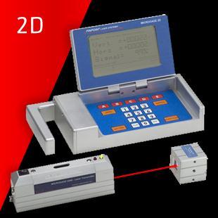
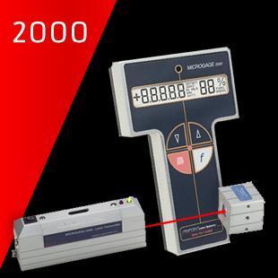
5 Alignment Equipment Needed Microgage 2D Alignment System with Cylindrical Laser; Microgage Receiver Cylindrical Mount; Marking Tape or Marker; Tape Measure; Notebook & Pencil; Microgage DCU & Pinpoint Capture software (optional); Laptop or PC for data storage & computations (optional). In addition to these basic items, you will need a collet or fixture that can hold both the laser and receiver cylindrical mount securely in-place. How it Works The self-contained, cylindrical Microgage laser is placed into the machine chuck, spindle or another rotating part of the machine. This laser projects a narrow beam that extends the centerline of the chuck or spindle down the length of the machine. A Microgage receiver is secured into an opposing spindle, attached to a moving tool holder, or similar machine element and collects the laser light. As the chuck is turned and/or the tool holder or opposing spindle moved the relative position of the laser beam to the Microgage receiver will move if misalignments are present. The receiver is connected to a Microgage display and precise readings are given as parts of the machine are turned and moved. Readings are recorded manually or with a laptop and Pinpoint s Capture software and calculations can be made to determine runout, concentricity errors, offsets, parallelism errors and other valuable information to diagnose machines and bring them back into alignment. Measuring Procedure First, the Microgage Cylindrical Laser is placed into the chuck, and spindle or a collet mount so that the laser beam can project along the axis of rotation. It is important to note that the laser beam will not be perfectly centered or parallel to the axis of rotation and may appear to be off the center of the tailstock centerline this is normal. The Microgage Laser typically has a 2 to 3 inch long mounting shank, of a precise cylindrical dimension, that is held in the chuck. The laser beam then travels some distance down the length of the machine before it reaches the Microgage Receiver. If the chuck does not grip the laser shank evenly or if there is any reason that the laser doesn t sit squarely in it s mounting Page 5
6 position the errors will be exaggerated over the run of the laser beam. For example, if a piece of debris such as a metal chip acts like a shim and the back end of the laser shank is moved off center by inch the laser beam will be deflected off the rotational centerline. So, a deflection acting over a 3 inch shank would translate to a inch beam deflection at a laser distance of 60 inches (0.005 / 3 = / 60 ). Considering the example above, if the chuck or spindle holding the laser is manually rotated the laser beam at 60 inches will produce a circular path that has a radius of inch or a diameter of inch. Not to worry, our alignment procedure compensates for this. Next, the Microgage receiver is secured into the Microgage 2D Bore Mount which places the dual axis receiver along the centerline of the shank or mounting surface (taper, locating hole, pin, etc.). The mount and receiver are then attached to the tail stock, tool holder or any other part of the machine tool that you are trying to check relative to the centerline of the chuck. Here again, it is important to note that the laser beam is unlikely to hit the exact center of the Microgage Receiver target. The stack up of moving parts, the elements of a machine tool and even parts of the measuring system contribute to this initial position of the laser beam on the receiver. At this point you are ready to turn on the Microgage Display, if you have not already done so, and start recording your readings for alignment. Making the Measurements Early in this application note we outlined two types of alignment error; offset and angular. The chuck or spindle is likely to have a little of each. The position and orientation of the tail stock may also contribute to an offset as well as an angular error. By taking a number of measurements with the Microgage Laser and Receiver in various rotational positions we are able to measure the combined offset and angular errors. Offset errors remain constant over the length of the machine while angular parallelism errors increase with distance down the length of the machine. Then by moving the receiver to a new location and repeating the measurements we can determine the individual angular error. Start by manually turning the chuck or spindle to a starting or home position and where the A on the laser housing is facing upwards.. Now, turn the chuck precisely ½ turn (180 degrees) until the D on the laser housing is facing upwards these two points are your rotational positions for taking measurements at the chuck. During the measurement run you do not want to move the laser in the chuck because this will disrupt your readings and alignment measurements. Similarly, the receiver is rotated through a precise1/2 turn for two measurement locations. We recommend label up and label down. You are now ready to start recording your measurements. The chart below shows the orientation of the laser transmitter and the receiver for each measurement. Move one element (chuck position or receiver) at a time and take your measurement. For each position you want to record both the vertical (Vert.) and the horizontal (Horz.) values being careful to note the sign of the measurement; either + or -. Page 6
7 Reading Chuck/Spindle Pos. Receiver Position Vertical Value Horizontal Value 1 A Label Up V1 H1 2 D Label Up V2 H2 3 D Label Down V3 H3 4 A Label Down V4 H4 These 8 recorded values can now be used to calculate the total error or misalignment between the spindle or chuck supporting the laser and the mounting point for the receiver. Using the formula below you can determine the vertical centerline position; [((V1 + V2) / 2) + ((V3 + V4) / 2))] / 2 = Vertical Centerline [((H1 + H2) / 2) + ((H3 + H4) / 2))] / 2 = Horizontal Centerline You should now know the direction and amount of adjustment needed to align to centerline. It may be necessary to repeat the measurements especially if you are looking for very small tolerances. Page 7
8 We have engineers standing by to answer any questions you may have. 8AM 5PM EST 8
Turning and Lathe Basics
 Training Objectives After watching the video and reviewing this printed material, the viewer will gain knowledge and understanding of lathe principles and be able to identify the basic tools and techniques
Introduction to Machining: Lathe Operation
 Introduction to Machining: Lathe Operation Lathe Operation Lathe The purpose of a lathe is to rotate a part against a tool whose position it controls. It is useful for fabricating parts and/or features
Lathe. A Lathe. Photo by Curt Newton
 Lathe Photo by Curt Newton A Lathe Labeled Photograph Description Choosing a Cutting Tool Installing a Cutting Tool Positioning the Tool Feed, Speed, and Depth of Cut Turning Facing Parting Drilling Boring
MACHINE TOOL ALIGNMENT TESTS
 MACHINE TOOL ALIGNMENT TESTS 39 MACHINE TOOL TESTING INTRODUCTION: The surface components produced by machining processes are mostly by generation. As a result, the quality of surface produced depends
Laboratory for Manufacturing Systems Department of Mechanical Engineering and Automation University of Patras, Greece
 COMPUTER NUMERICAL CONTROL OF MACHINE TOOLS Laboratory for Manufacturing Systems Department of Mechanical Engineering and Automation University of Patras, Greece Chapter 4: Tool Changing and Tool Registers
CNC EXPANDING MANDRELS
 CNC EXPANDING MANDRELS ID CLAMPING OFFERS FULL OD PART ACCESS PARALLEL EXPANSION FOR OPTIMUM ACCURACY AND GRIP FORCE LARGE RANGE IN STOCK FOR IMMEDIATE SHIPMENT ROYAL CNC EXPANDING MANDRELS Rigid and Accurate
TURNING BORING TURNING:
 TURNING BORING TURNING: FACING: Machining external cylindrical and conical surfaces. Work spins and the single cutting tool does the cutting. Done in Lathe. Single point tool, longitudinal feed. Single
The Kruger Eccentric
 The Kruger Eccentric Instructions for Use of the Dual Taper Reel Seat Filler and Eccentric Reel Seat Recess Turning Mandrels Rick Kruger 503-860-6346 krugerr@easystreet.net The Dual Taper Reel Seat Filler
MONASET CM-2. Has these customer proven features...
 MONASET CM-2 Has these customer proven features... We looked at our successful Monaset grinder very closely before we came up with the engineering refinements which, when combined with its field proven
JOB QUALIFICATION STANDARD (JQS)
") Occupation: Work Process: MACHINIST (CNC) CNC Setup Practical Hours: 2000 hrs. DOL Standard: CNC Setup: Apply a working knowledge in the setup of Computer Numerical Controls (CNC) machines that execute
Occupation: Work Process: MACHINIST (CNC) CNC Setup Practical Hours: 2000 hrs. DOL Standard: CNC Setup: Apply a working knowledge in the setup of Computer Numerical Controls (CNC) machines that execute
Lathes. CADD SPHERE Place for innovation Introduction
 Lathes Introduction Lathe is one of the most versatile and widely used machine tools all over the world. It is commonly known as the mother of all other machine tool. The main function of a lathe is to
When the machine makes a movement based on the Absolute Coordinates or Machine Coordinates, instead of movements based on work offsets.
 Absolute Coordinates: Also known as Machine Coordinates. The coordinates of the spindle on the machine based on the home position of the static object (machine). See Machine Coordinates Absolute Move:
COLLET CLOSERS, FIXTURES AND COLLETS FOR ROTATING AND FIXED APPLICATIONS
 COLLET CLOSERS, FIXTURES AND COLLETS FOR ROTATING AND FIXED APPLICATIONS ROYAL QUICK-GRIP MANUAL COLLET FIXTURES FOR 4TH AND 5TH AXIS APPLICATIONS q Unit is actuated via a hybrid mechanical/hydraulic mechanism.
ROYAL ULTRA-PRECISION ER COLLETS " TIR
 ROYAL C EXPANDING COLLETS q Unlike chucks and most collets that grip the OD of a workpiece, C expanding collets are designed to grip on the ID of a part. q Accu-length design ensures precise workpiece
Copyright 2009 Society of Manufacturing Engineers. FUNDAMENTALS OF TOOL DESIGN Fixture Design - DF
 FUNDAMENTALS OF TOOL DESIGN Fixture Design - DF SCENE 1. DF26A, FTD87, 03:20:15:00-03:20:46:00 zoom out, milling operation DF26B, CGS: Milling Fixtures Lathe Fixtures Grinding Fixtures Broaching Fixtures
Table of Contents. Preface 9 Prerequisites 9. Key Concept 1: Know Your Machine From A Programmer s Viewpoint 13. Table of Contents
 Preface 9 Prerequisites 9 Basic machining practice experience 9 Controls covered 10 Limitations 10 Programming method 10 The need for hands -on practice 10 Instruction method 11 Scope 11 Key Concepts approach
Typical Parts Made with These Processes
 Turning Typical Parts Made with These Processes Machine Components Engine Blocks and Heads Parts with Complex Shapes Parts with Close Tolerances Externally and Internally Threaded Parts Products and Parts
VHF 3 VHF 3. Universal Milling Machine. Rigid Universal Milling Machine for drilling and milling, with large travels.
 Universal Milling Machine Rigid Universal Milling Machine for drilling and milling, with large travels incl. 3-axis position indicator travel distances X axis 750 mm Y axis 280 mm Z axis 430 mm speed range
Lathe Accessories. Work-holding, -supporting, and driving devices
 46-1 Lathe Accessories Divided into two categories Work-holding, -supporting, and driving devices Lathe centers, chucks, faceplates Mandrels, steady and follower rests Lathe dogs, drive plates Cutting-tool-holding
WF WF Tool Milling Machines. Milling Machines for Die Making with digital position indicator.
 Tool Milling Machines Milling Machines for Die Making with digital position indicator automatic feeds on all 3 axes vertical head quill for drilling quill stroke 3" versatile for many applications for
Mill Specifications. FEATURE 5000(5100) 5400(5410) 2000 (2010) Max clearance, table to spindle
 5400(5410) 2000 (2010) Max clearance, table to spindle") Mill Specifications FEATURE 5000(5100) 5400(5410) 2000 (2010) Max clearance, table to spindle 8.00" (203 mm) 8.00" (203 mm) 9.00" (229 mm) Throat (without headstock spacer block) Throat (with headstock
Mill Specifications FEATURE 5000(5100) 5400(5410) 2000 (2010) Max clearance, table to spindle 8.00" (203 mm) 8.00" (203 mm) 9.00" (229 mm) Throat (without headstock spacer block) Throat (with headstock
WF WF Tool Milling Machines. Milling Machines for Die Making with digital position indicator.
 Tool Milling Machines Milling Machines for Die Making with digital position indicator automatic feeds on all 3 axes vertical head quill for drilling quill stroke 80 mm versatile for many applications for
Answers to Questions and Problems
 Fundamentals of Geometric Dimensioning and Tolerancing Using Critical Thinking Skills 3 rd Edition By Alex Krulikowski Answers to Questions and Problems Second Printing Product #: 1103 Price: $25.00 Copyright
General advice on work safety
 General advice on work safety To prevent injury to the lathe operator and other persons the relevant safety regulations laid down by the Professional Trade Association (UVV) must be observed at all times.
Table of Contents. Table of Contents. Preface 11 Prerequisites... 12
 Table of Contents Preface 11 Prerequisites... 12 Basic machining practice experience... 12 Controls covered... 12 Limitations... 13 The need for hands -on practice... 13 Instruction method... 13 Scope...
Tooltech Precision Reamers are designed to meet hole geometry requirements in the complex and demanding machining environment of today s manufacturing
 BLADED REAMERS Tooltech Precision Reamers are designed to meet hole geometry requirements in the complex and demanding machining environment of today s manufacturing industry. The innovative design of
SHERLINE Drill Chucks
 SHERLINE Drill Chucks P/N 1010/1015 (5/32"), P/N 1072 (1/4") and P/N 1069 (3/8") Chuck and Drill Sizes The size of the chuck indicates the largest size drill shank it will hold. Larger chucks will hold
Universal Machining Chucks. 4-Jaw Vertical
 Universal Machining Chucks 4-Jaw Vertical Parts are gripped firmly by the formed jaws, ensuring high precision (deviation within 0.03mm) Large workpieces can be held tight with the low profile vise body
3D SENSORS 2-in-1 3-AXIS EDGE FINDER & MEASURING INSTRUMENT.
 3D SENSORS 2-in-1 3-AXIS EDGE FINDER & MEASURING INSTRUMENT www.haimer-usa.com HAIMER Sensors Benefits 1. No math needed Zero on the indicator = Zero on the machine control The sensor is pre-calibrated
Trade of Toolmaking Module 2: Turning Unit 3: Drilling, Reaming & Tapping Phase 2
 Trade of Toolmaking Module 2: Turning Unit 3: Drilling, Reaming & Tapping Phase 2 Published by SOLAS 2014 Unit 3 1 Table of Contents Document Release History... 3 Unit Objective... 4 Introduction... 4
MANUFACTURING TECHNOLOGY
 MANUFACTURING TECHNOLOGY UNIT V Machine Tools Milling cutters Classification of milling cutters according to their design HSS cutters: Many cutters like end mills, slitting cutters, slab cutters, angular
VHF 2 VHF 2. Vertical Milling Machine
 Vertical Milling Machine VHF - ideal series for mechanic workshops, training, single part and replacement part manufacturing, and prototyping including 3-axis position indicator travel x-axis 600 mm y-axis
SUMMARY. Valves, pipes and manifold-type parts are ideal candidates for Turn-Cut.
 SUMMARY Turn-Cut is a programming option available on Okuma horizontal machining centers that allows the machine to create bores and diameters that include circular and/or angular features. It allows users
Turning. MECH Dr Ghassan Al-Kindi - Lecture 10 1
 Turning Single point cutting tool removes material from a rotating workpiece to generate a cylinder Performed on a machine tool called a lathe Variations of turning performed on a lathe: Facing Contour
Dozuki. Written By: Dozuki System. Guide to calibrating the Haas wireless intuitive probing system. How to Calibrate WIPS
 Dozuki How to Calibrate WIPS Guide to calibrating the Haas wireless intuitive probing system. Written By: Dozuki System 2017 www.dozuki.com Page 1 of 22 INTRODUCTION Getting Started On initial setup or
Motion Manipulation Techniques
 Motion Manipulation Techniques You ve already been exposed to some advanced techniques with basic motion types (lesson six) and you seen several special motion types (lesson seven) In this lesson, we ll
STEVENS SUBPLATES. STEVENS ENGINEERING, INC. TOLL-FREE WEB FAX
 STEVENS SUBPLATES Spacing of hole patterns on Stevens accessories is identical to the pattern on Stevens Subplates. Insertion of the pull dowels thru bushed holes in the accessory into corresponding bushed
Other Lathe Operations
 Chapter 15 Other Lathe Operations LEARNING OBJECTIVES After studying this chapter, students will be able to: Safely set up and operate a lathe using various work-holding devices. Properly set up steady
4. DOUBLE ECCENTRICS 5. WORM DRIVE SHAFT
 Quality Manufacturing Processes 's GD5C2 has higher accuracy, more spindle clearance and more thrust and radial load. All rotary products are manufactured in Elmira, New York to strict specifications.
PREVIEW COPY. Table of Contents. Lesson One Machining Cylindrical Shapes...3. Lesson Two Drilling, Reaming, and Honing...21
 Table of Contents Lesson One Machining Cylindrical Shapes...3 Lesson Two Drilling, Reaming, and Honing...21 Lesson Three Lesson Four Machining Flat Surfaces...37 Determining Tolerances and Finishes...53
2 ¾ D Machining On a 4 Axis RF-30 Mill/Drill, version 1.4
 2 ¾ D Machining On a 4 Axis RF-30 Mill/Drill, version 1.4 By R. G. Sparber Copyleft protects this document. 1 It would not be hard to make this part with a 5 axis screw machine and the related 3D software
MACHINE TOOL ACCESSORIES
 VERTICAL 5-C COLLET VISE SERIES 344: VERTICAL 3-C COLLET VISE SERIES 344: : 2-1/2 x 7-3/4 Height: 4 Small movement of lever opens or closes collet. 2030000 CAM OPERATED 5-C HORIZONTAL/VERTICAL COLLET FIXTURE
ROOP LAL Unit-6 Lathe (Turning) Mechanical Engineering Department
 Mechanical Engineering Department") Notes: Lathe (Turning) Basic Mechanical Engineering (Part B) 1 Introduction: In previous Lecture 2, we have seen that with the help of forging and casting processes, we can manufacture machine parts of
Notes: Lathe (Turning) Basic Mechanical Engineering (Part B) 1 Introduction: In previous Lecture 2, we have seen that with the help of forging and casting processes, we can manufacture machine parts of
CNC Turning. Module 3: CNC Turning Machine. Academic Services PREPARED BY. January 2013
 CNC Turning Module 3: CNC Turning Machine PREPARED BY Academic Services January 2013 Applied Technology High Schools, 2013 Module 3: CNC Turning Machine Module Objectives Upon the successful completion
Chapter 23. Machining Processes Used to Produce Round Shapes: Turning and Hole Making
 Chapter 23 Machining Processes Used to Produce Round Shapes: Turning and Hole Making R. Jerz 1 2/24/2006 Processes Turning (outside surface) straight, taper, facing, contour, form, cut-off, threading,
Agilent 10717A Wavelength Tracker
 7I Agilent 10717A Wavelength Tracker MADE Description Description The Agilent 10717A Wavelength Tracker (see Figure 7I-1) uses one axis of a laser measurement system to report wavelength-of-light changes,
Geometric Dimensioning and Tolerancing
 Geometric dimensioning and tolerancing (GDT) is Geometric Dimensioning and Tolerancing o a method of defining parts based on how they function, using standard ASME/ANSI symbols; o a system of specifying
TOP WORK ISO 9001.CE UNIVERSAL CUTTER & TOOL GRINDER
 TOP WORK ISO 9001.CE UNIVERSAL CUTTER Precise ball groove of conformation Inclination of Wheelhead The wheelhead can easily tilt up to ±15 degrees, with a 360-degrees swivel on the horizontal plane. The
JOB QUALIFICATION STANDARD (JQS)
") Occupation: Work Process: Maintenance Mechanic Machine Shop Practical Hours: 250 hrs. JOB QUALIFICATION STANDARD (JQS) DOL Standard: Manual Machining Fundamentals: Apply a working knowledge of metal removal
Occupation: Work Process: Maintenance Mechanic Machine Shop Practical Hours: 250 hrs. JOB QUALIFICATION STANDARD (JQS) DOL Standard: Manual Machining Fundamentals: Apply a working knowledge of metal removal
Complete O.D. Machining in One Operation
 MFDODM209 Complete O.D. Machining in One Operation Including: Hydra-Drive For Extreme Accuracy CREATING INNOVATIONS IN FACE DRIVING TECHNOLOGY www.facedrivers.com Complete O.D. Machining in one Operation
Chapter 22 MACHINING OPERATIONS AND MACHINE TOOLS
 Chapter 22 MACHINING OPERATIONS AND MACHINE TOOLS Turning and Related Operations Drilling and Related Operations Milling Machining Centers and Turning Centers Other Machining Operations High Speed Machining
How to Calibrate a CNC Machine's Positioning System
 How to Calibrate a CNC Machine's Positioning System Guide to calibrating the Haas wireless intuitive probing system. Written By: Kim Payne 2018 gunnerautomotive.dozuki.com/ Page 1 of 20 INTRODUCTION Attention:
A study of accuracy of finished test piece on multi-tasking machine tool
 A study of accuracy of finished test piece on multi-tasking machine tool M. Saito 1, Y. Ihara 1, K. Shimojima 2 1 Osaka Institute of Technology, Japan 2 Okinawa National College of Technology, Japan yukitoshi.ihara@oit.ac.jp
Power Generation. Application Notes
 1. Application Notes Power Generation System Recommendations Turbines Split-Joint Flatness Rotating Equipment L-705 Turbine Alignment System L-740 Leveling Laser System S-680 5-Axis Shaft Alignment System
MF 1 MF 1 V MF 1 MF 1 V. Multipurpose Milling Machines. Most widely used milling machine type word-wide!
 Multipurpose Milling Machines Most widely used milling machine type word-wide! with 3 axes position indicator head swivels through 3 axes swivel r + l ± 90 ilt forward + reverse ± 45 rotation on the column
DIRECTION FOR USE Evid. č
 DIRECTION FOR USE Evid. č. 1520304 SAFETY THREAD-CUTTING HEADS Zhb 21, Zhb 31, Zhb 41, Zhb 51 Zhb 21A, Zhb 31A, Zhb 41A Manufacturer: NAREX MTE s.r.o., Moskevská 63, CZ-10100 Praha 10, Czech Republic Tel:
Work Holding Principles ITCD Rajeev Madhavan Nair
 Work Holding Principles ITCD 301-001 Work Holding One of the most important elements of the machining process Work holder includes all devices that hold, grip or chuck a work piece to perform a manufacturing
ISO 9001.CE. MONASET Tool Grinder.
 ISO 9001.CE MONASET Tool Grinder www.topwork.com.tw FEATURE CM-A & CM-2 sharpen and recondition complex tool shapes and parts. Turntable and guide bar allows workpieces grinding from different direction.
L-742 Ultra-Precision Roll Alignment System for Printing Presses/Paper Machines
 ujijijijijijijijijijijijijijijijijijijijijijijijijijijijijijijijijijijijijijijijijijijijijijijijijijijijijijijijijijijijiji Application Notes Roll Alignment System Recommendations Printing Presses/Paper
LinuxCNC Help for the Sherline Machine CNC System
 WEAR YOUR SAFETY GLASSES FORESIGHT IS BETTER THAN NO SIGHT READ INSTRUCTIONS BEFORE OPERATING LinuxCNC Help for the Sherline Machine CNC System LinuxCNC Help for Programming and Running 1. Here is a link
Precision made in Germany. As per DIN The heart of a system, versatile and expandable.
 1 Precision made in Germany. As per DIN 8606. The heart of a system, versatile and expandable. Main switch with auto-start protection and emergency off. Precision lathe chuck as per DIN 6386 (Ø 100mm).
BSF. Large Ratio Automatic Back Counterboring & Spotfacing Tool
 BSF Large Ratio Automatic Back Counterboring & Spotfacing Tool Counterbores up to 2.3xd Replaceable carbide coated blades for extended life Very simple to use Suitable for CNC machines with through coolant
Dimensioning. Dimensions: Are required on detail drawings. Provide the shape, size and location description: ASME Dimensioning Standards
 Dimensioning Dimensions: Are required on detail drawings. Provide the shape, size and location description: - Size dimensions - Location dimensions - Notes Local notes (specific notes) General notes ASME
Hardinge. The Hardinge Advantage. Hardinge Inc. One Hardinge Drive Elmira, NY USA. Worldwide Leader in Super-Precision
 The Hardinge Advantage Worldwide Leader in Super-Precision Hardinge Inc. One Hardinge Drive Elmira, NY 14902-1507 USA Phone: 800-843-8801 Fax: 607-734-3886 Internet: www.hardinge.com Hardinge Inc., 1997
Turning and Related Operations
 Turning and Related Operations Turning is widely used for machining external cylindrical and conical surfaces. The workpiece rotates and a longitudinally fed single point cutting tool does the cutting.
5 Micron Collets. The New Standard in AA Grade Toolholding. Introducing Extreme Precision
 Introducing Extreme Precision 5 Micron Collets The New Standard in AA Grade Toolholding Increased Tool ife Evenly distributed cutting edges for high performance machining Consistent cutting profiles ensure
Machine Tools MILLING PROCESS. BY LAKSHMIPATHI YERRA Asst.professor Dept.of Mechanical Engg.
 Machine Tools MILLING PROCESS BY LAKSHMIPATHI YERRA Asst.professor Dept.of Mechanical Engg. FIG. 1 Typical parts and shapes produced by various cutting processes Fig. 2 Schematic illustration of milling
NEXT ARE (6) BLOCKS THAT MEASURE 7/8"+ (.885") THICK X 1-1/4"+ (1.255") TALL X 1-1/2" (1.500") LONG. SAME DRILL AND TAP PATTERN AS THE 4 ABOVE!!!
 BLOCKS THAT MEASURE 7/8+ (.885) THICK X 1-1/4+ (1.255) TALL X 1-1/2 (1.500) LONG. SAME DRILL AND TAP PATTERN AS THE 4 ABOVE!!!") 1"- 2" - 3" BLOCKS HAVE (4 total) TAPPED 1/4" X 20 in 1" thick face alone AND (2) TAPPED HOLES 3/8" X 16 IN 1" THICKNESS AS SHOWN. BLOCKS ALSO HAVE (6) DRILLED 25/64" HOLES WITH (8) 9/16" COUNTER-BORES
1"- 2" - 3" BLOCKS HAVE (4 total) TAPPED 1/4" X 20 in 1" thick face alone AND (2) TAPPED HOLES 3/8" X 16 IN 1" THICKNESS AS SHOWN. BLOCKS ALSO HAVE (6) DRILLED 25/64" HOLES WITH (8) 9/16" COUNTER-BORES
Chapter 22: Turning and Boring Processes. DeGarmo s Materials and Processes in Manufacturing
 Chapter 22: Turning and Boring Processes DeGarmo s Materials and Processes in Manufacturing 22.1 Introduction Turning is the process of machining external cylindrical and conical surfaces. Boring is a
Multipurpose Milling Machine Servomill 700. Conventional Multipurpose Milling Machine.
 Multipurpose Milling Machine Conventional Multipurpose Milling Machine For workshop application, single parts production and training purposes Servo motors and preloaded ball screws on all axes Infinitely
Shot Peening Small Holes By Bill Barker PROGRESSIVE TECHNOLOGIES
 Shot Peening Small Holes By Bill Barker PROGRESSIVE TECHNOLOGIES Many rotating components have holes or slots that require shot peening for fatigue resistance and life enhancement. This discussion outlines
Precision Chucks for Improved Accuracy and Increased Productivity
 Precision Workholding Technology Precision Chucks for Improved Accuracy and Increased Productivity Precision Air Chucks (Self Contained Design) MicroCentric Precision Air Chucks feature a patented open
Engineering & Design: Geometric Dimensioning
 Section Contents NADCA No. Format Page Frequently Asked Questions -2 s e c t i o n 1 Introduction -2 2 What is GD&T? -2 3 Why Should GD&T be Used? -2 4 Datum Reference Frame -4 4.1 Primary, Secondary,
Machine Tool Technology/Machinist CIP Task Grid
 1 Secondary Task List 100 ORIENTATION / SAFETY 101 Describe the Occupational Safety and Health Administration (OSHA) and its role in the machoning industry. 102 Identify & explain safety equipment and
The new generation with system accessories. Made in Germany!
 1 The new generation with system accessories. Made in Germany! For face, longitudinal and taper turning, thread-cutting. For machining steel, brass, aluminium and plastic. Mounting flange for fastening
COLLET FIXTURES, CHUCKS AND COLLETS FOR MACHINING CENTERS ROTARY TABLES MANUAL LATHES GRINDERS
 OLLET FIXTURES, HUKS N OLLETS FOR MHINING ENTERS ROTRY TLES MNUL LTHES GRINERS ROYL QUIK-GRIP POWER-LOK HYRULI OLLET FIXTURES Extremely Fast ollet hanges hanging collets on a Royal Quick-Grip Power-lock
PERFORMANCE RACING AND ENGINE BUILDING MACHINERY AND EQUIPMENT
 PERFORMANCE RACING AND ENGINE BUILDING MACHINERY AND EQUIPMENT F68A Programmable Automatic Machining Center AC Servo Motors and Power Drawbar Hardened Box Way Column Touch Screen Control INDUSTRY EXCLUSIVE
TRAINING MANUAL. Part INTRODUCTION TO TWIST DRILLS
 PRESTO INTERNATIONAL UK LTD TRAINING MANUAL Part 2 INTRODUCTION TO TWIST DRILLS - 1 - DEFINITION:- A rotary end cutting tool having two or more cutting lips, and having two or more spiral (helical) or
Useful accessories for lathe and milling systems.
 1 Useful accessories for lathe and milling systems. Nearly all accessories are supplied in wooden boxes. For proper and value preserving storage! Dividing attachment TA 250 For precision lathe PD 250/E,
Figure 1: NC Lathe menu
 Click To See: How to Use Online Documents SURFCAM Online Documents 685)&$0Ã5HIHUHQFHÃ0DQXDO 5 /$7+( 5.1 INTRODUCTION The lathe mode is used to perform operations on 2D geometry, turned on two axis lathes.
Chapter 23 Drilling and Hole Making Processes. Materials Processing. Hole Making Processes. MET Manufacturing Processes
 MET 33800 Manufacturing Processes Chapter 23 Drilling and Hole Making Processes Before you begin: Turn on the sound on your computer. There is audio to accompany this presentation. Materials Processing
» Modular clamping elements for optical or optical/tactical measurement» For high-precision edge measurements in reflected and transmitted light
 » Modular clamping elements for optical or optical/tactical measurement» For highprecision edge measurements in reflected and transmitted light» Toothed rails as workpiece stops or for fastening clamping
Processing and Quality Assurance Equipment
 Processing and Quality Assurance Equipment The machine tool, the wash station, and the coordinate measuring machine (CMM) are the principal processing equipment. These machines provide the essential capability
The new generation with system accessories. Made in Germany!
 1 The new generation with system accessories. Made in Germany! For face, longitudinal and taper turning, thread-cutting. For machining steel, brass, aluminium and plastic. Mounting flange for fastening
Various other types of drilling machines are available for specialized jobs. These may be portable, bench type, multiple spindle, gang, multiple
 Drilling The process of making holes is known as drilling and generally drilling machines are used to produce the holes. Drilling is an extensively used process by which blind or though holes are originated
at the lathe by Jon Siegel Tuning Your Lathe Testing Lathe Alignment
 at the lathe by Jon Siegel This is the second of a two-part article Tuning Your Lathe Testing & correcting the accuracy of your lathe To get the best performance from your lathe you need to check the accuracy
8029 S 200th St. Kent, WA USA Ph: Fax:
 8029 S 200th St. Kent, WA 98032 USA Ph: 253-872-7050 Fax: 253-395-0230 18.09.2018 ORDERING PROCEDURE Contact your regional Rottler sales rep for assistance in ordering optional equipment, replacement
Collet Closer & Tailstock Options
 Collet Closer & Tailstock Options Fail-Safe Collet Closers Spring-close, air-to-open for fail-safe operation (85psi max) Part remains clamped even if loss of air should occur Non-adjustable grip force
Chapter 23: Machining Processes: Hole Making Part A (Lathe Operations, Boring, Reaming, Tapping)
") 1 Manufacturing Processes (2), IE-352 Ahmed M El-Sherbeeny, PhD Spring 2017 Manufacturing Engineering Technology in SI Units, 6 th Edition Chapter 23: Machining Processes: Hole Making Part A (Lathe Operations,
1 Manufacturing Processes (2), IE-352 Ahmed M El-Sherbeeny, PhD Spring 2017 Manufacturing Engineering Technology in SI Units, 6 th Edition Chapter 23: Machining Processes: Hole Making Part A (Lathe Operations,
Miyano Evolution Line
 Evolution Line CNC Turning center with 2 spindles, 2 turrets and 1 -axis slide BNJ-34/42/51 "Evolution and Innovation" is the Future What could not be done can be done. -axis movement is added to the traditional
Dual Contact System. For High Speeds. Hydraulic Chuck. Runout Adjustable Chuck
 Dual Contact System Dual Contact System Dual Contact System Features P1 BIG-PLUS Spindle System S P I N D L E S Y S T E M Dual contact spindle system BBT SHANK A1 BDV SHANK B2 HSK TOOLING SYSTEM Features
1640DCL Digital Control Lathe
 1640DCL Digital Control Lathe MACHINE SPECIFICATIONS Multiple Function CNC Lathe 1. Manual Hand wheel Operation 2. CNC G-Code Operation 16.1 swing over bed, 8.6 swing over cross-slide 2.05 diameter hole
Chapter 23: Machining Processes: Turning and Hole Making
 Manufacturing Engineering Technology in SI Units, 6 th Edition Chapter 23: Machining Processes: Turning and Hole Making Chapter Outline 1. Introduction 2. The Turning Process 3. Lathes and Lathe Operations
UNIVERSAL CENTRE LATHES
 UNIVERSAL CENTRE LATHES TRADITION AND EXPERIENCE SR 6000 SR 2000 ŠKODA machine tools of different type and variant have been present in the world market for over 100 years. Among them were a lot of special
Ahsanullah University of Science and Technology (AUST) Department of Mechanical and Production Engineering
 Department of Mechanical and Production Engineering") Ahsanullah University of Science and Technology (AUST) Department of Mechanical and Production Engineering LABORATORY MANUAL For the students of Department of Mechanical and Production Engineering 1 st
Ahsanullah University of Science and Technology (AUST) Department of Mechanical and Production Engineering LABORATORY MANUAL For the students of Department of Mechanical and Production Engineering 1 st
Complete Dovetail Jig Instructions
 Complete Dovetail Jig Instructions 15 18 4 3 1 12 13 8 19 17 16 6 14 5 9 11 10 2 9 PARTS LIST - Complete Dovetail Jig Introduction Your new dovetail jig will cut Full Through Dovetails and three varieties
LocoGear. Technical Bulletin - 02 January 11, by LocoGear LIVE STEAM CASTINGS. Tech Bulletin - 02
 LIVE STEAM CASTINGS Tech Bulletin - 02 LocoGear Technical Bulletin - 02 January 11, 2003 2003 by LocoGear John D.L. Johnson 3879 Woods Walk Blvd. Lake Worth, FL 33467-2359 jjohnson@locogear.com www.locogear.com
Basic Digital Read-Out Functionality on a Mill
 Basic Digital Read-Out Functionality on a Mill By R. G. Sparber Copyleft protects this document 1. There is a running joke among owners of Digital Read-Out (DRO) What is the cleanest thing in any shop?
Lathe is a machine, which removes the metal from a piece of work to the required shape & size HENRY MAUDSLAY
 TURNING MACHINES LATHE Introduction Lathe is a machine, which removes the metal from a piece of work to the required shape & size HENRY MAUDSLAY - 1797 Types of Lathe Engine Lathe The most common form
Method for establishing machine tool performance specifications from part tolerance requirements
 Method for establishing machine tool performance specifications from part tolerance requirements R. Callaghan Independent Quality Labs, Inc., USA Abstract Design Engineers are accustomed to using tools