Fundamentals of Machining/Orthogonal Machining
|
|
|
- Geoffrey Sutton
- 6 years ago
- Views:
Transcription
1 Fundamentals of Machining/Orthogonal Machining Chapter 20
2 20.1 Introduction
3 FIGURE 20-1 The fundamental inputs and outputs to machining processes.
4 20.2 Fundementals
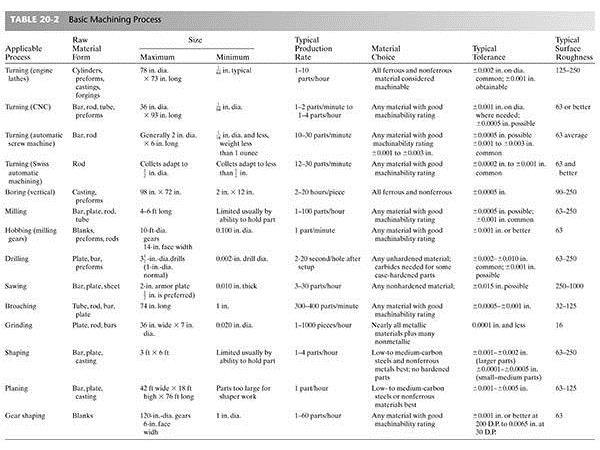
5 FIGURE 20-2 The seven basic machining processes used in chip formation.
6 FIGURE 20-3 Turning a cylindrical workpiece on a lathe requires you to select the cutting speed, feed, and depth of cut.

7 FIGURE 20-4 Examples of a table for selection of speed and feed for turning. (Source: Metcut s Machinability Data Handbook.)

8 FIGURE 20-4 Examples of a table for selection of speed and feed for turning. (Source: Metcut s Machinability Data Handbook.)
9 FIGURE 20-5 Relationship of speed, feed, and depth of cut in turning, boring, facing, and cutoff operations typically done on a lathe.
10
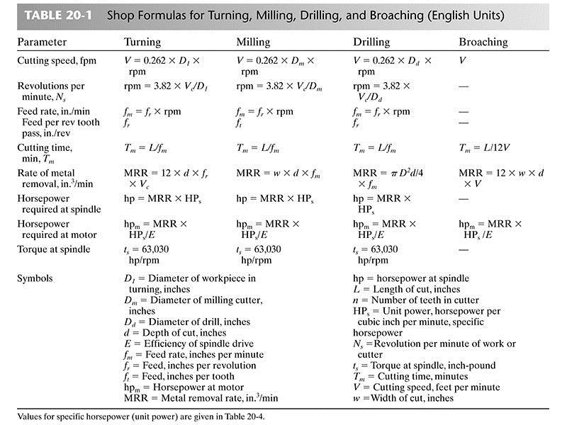
11 FIGURE 20-6 Basics of milling processes (slab, face, and end milling) including equations for cutting time and metal removal rate (MRR).
12 FIGURE 20-7 Basics of the drilling (hole-making) processes, including equations for cutting time and metal removal rate (MRR).
13 FIGURE 20-8 Process basics of broaching. Equations for cutting time and metal removal rate (MRR) are developed in Chapter 26
14 FIGURE 20-9 (a) Basics of the shaping process, including equations for cutting time (Tm ) and metal removal rate (MRR). (b) The relationship of the crank rpm Ns to the cutting velocity V.
15 FIGURE Operations and machines used for machining cylindrical surfaces.
16 FIGURE Operations and machines used for machining cylindrical surfaces.
17 FIGURE Operations and machines used to generate flat surfaces.
18 20.3 Energy and Power in Machining
19
20 FIGURE Oblique machining has three measurable components of forces acting on the tool. The forces vary with speed, depth of cut, and feed.
21
22 FIGURE Three ways to perform orthogonal machining. (a) Orthogonal plate machining on a horizontal milling machine, good for low-speed cutting. (b) Orthogonal tube turning on a lathe; high-speed cutting (see Figure 20-16). (c) Orthogonal disk machining on a lathe; very high-speed machining with tool feeding (ipr) in the facing direction
23 20.4 Orthogonal Machining (Two Forces)
24 FIGURE Schematics of the orthogonal plate machining setups. (a) End view of table, quick-stop device (QSD), and plate being machined for OPM. (b) Front view of horizontal milling machine. (c) Orthogonal plate machining with fixed tool, moving plate. The feed mechanism of the mill is used to produce low cutting speeds. The feed of the tool is t and the DOC is w, the width of the plate.
25 FIGURE Orthogonal tube turning (OTT) produces a two-force cutting operation at speeds equivalent to those used in most oblique machining operations. The slight difference in cutting speed between the inside and outside edge of the chip can be neglected.

26 FIGURE Videograph made from the orthogonal plate machining process.
27 FIGURE Schematic representation of the material flow, that is, the chip-forming shear process. f defines the onset of shear or lower boundary. c defines the direction of slip due to dislocation movement.
 Discontinuous, continuous, and continuous with built-up edge. Chip samples produced by quick-stop technique.")
28 FIGURE Three characteristic types of chips. (Left to right) Discontinuous, continuous, and continuous with built-up edge. Chip samples produced by quick-stop technique. (Courtesy of Eugene Merchant (deceased) at Cincinnati Milacron, Inc., Ohio.)
29 20.5 Merchant s Model
30 FIGURE Velocity diagram associated with Merchant s orthogonal machining model.
31 20.6 Mechanics of Machining (Statics)
32 FIGURE Free-body diagram of orthogonal chip formation process, showing equilibrium condition between resultant forces R and R.
33 FIGURE Merchant s circular force diagram used to derive equations for Fs, Fr, Ft, and N as functions of Fc, Fr, f, a, and b.
34 20.7 Shear Strain and Shear Front Angle
35 FIGURE Shear stress ts variation with the Brinell hardness number for a group of steels and aerospace alloys. Data of some selected fcc metals are also included. (Adapted with permission from S. Ramalingham and K. J. Trigger, Advances in Machine Tool Design and Research, 1971, Pergamon Press.)

36 FIGURE The Black Huang stack-of-cards model for calculating shear strain in metal cutting is based on Merchant s bubble model for chip formation, shown on the left.
37 20.8 Mechanics of Machining (Dynamics)
38 FIGURE Machining dynamics is a closed-loop interactive process that creates a force-displacement response.
39 FIGURE There are three types of vibration in machining.
40 FIGURE Some examples of chatter that are visible on the surfaces of the workpiece.
41 FIGURE When the overlapping cuts get out of phase with each other, a variable chip thickness is produced, resulting in a change in Fc on the tool or workpiece.
42 FIGURE Regenerative chatter in turning and milling produced by variable uncut chip thickness.
43 FIGURE Milling and boring operations can be made more stable by correct selection of insert geometry.

44 FIGURE Dynamic analysis of the cutting process produces a stability lobe diagram, which defines speeds that produce stable and unstable cutting conditions.
45 FIGURE Distribution of heat generated in machining to the chip, tool, and workpiece. Heat going to the environment is not shown. Figure based on the work of A. O. Schmidt.
46 FIGURE There are three main sources of heat in metal cutting. (1) Primary shear zone. (2) Secondary shear zone tool chip (T C) interface. (3) Tool flank. The peak temperature occurs at the center of the interface, in the shaded region.
47 FIGURE The typical relationship of temperature at the tool chip interface to cutting speed shows a rapid increase. Correspondingly, the tool wears at the interface rapidly with increased temperature, often created by increased speed.
48 20.9 Summary
Materials & Processes in Manufacturing
 2003 Bill Young Materials & Processes in Manufacturing ME 151 Chapter 21 Fundamentals of Chip Type Machining Processes 1 Materials Processing 2003 Bill Young 2 Introduction Machining is the process of
THEORY OF METAL CUTTING
 THEORY OF METAL CUTTING INTRODUCTION Overview of Machining Technology Mechanism of chip formation Orthogonal and Oblique cutting Single Point and Multipoint Cutting Tools Machining forces - Merchant s
 VALLIAMMAI ENGINEERING COLLEGE DEPARTMENT OF MECHANICAL ENGINEERING QUESTION BANK ME6402 MANUFACTURING TECHNOLOGY II UNIT-I PART A 1. List the various metal removal processes? (BT1) 2. Explain how chip
 DEPARTMENT OF MECHANICAL ENGINEERING QUESTION BANK ME6402 MANUFACTURING TECHNOLOGY II UNIT I PART A 1. List the various metal removal processes? 2. How chip formation occurs in metal cutting? 3. What is
Manufacturing Science-II (EME-503)
") Time: 1 Hour B.Tech. [SEM V (ME-5 All Groups)] QUIZ TEST-1 Manufacturing Science-II ` Max. Marks: 30 Note: Attempt all the questions Q1) How metal is removed in metal cutting? Explain by giving any simple
Time: 1 Hour B.Tech. [SEM V (ME-5 All Groups)] QUIZ TEST-1 Manufacturing Science-II ` Max. Marks: 30 Note: Attempt all the questions Q1) How metal is removed in metal cutting? Explain by giving any simple
Roll No. :.. Invigilator s Signature :.. CS/B.Tech (ME)/SEM-5/ME-504/ TECHNOLOGY OF MACHINING. Time Allotted : 3 Hours Full Marks : 70
/SEM-5/ME-504/ TECHNOLOGY OF MACHINING. Time Allotted : 3 Hours Full Marks : 70") Name : Roll No. :.. Invigilator s Signature :.. CS/B.Tech (ME)/SEM-5/ME-504/2009-10 2009 TECHNOLOGY OF MACHINING Time Allotted : 3 Hours Full Marks : 70 The figures in the margin indicate full marks. Candidates
Name : Roll No. :.. Invigilator s Signature :.. CS/B.Tech (ME)/SEM-5/ME-504/2009-10 2009 TECHNOLOGY OF MACHINING Time Allotted : 3 Hours Full Marks : 70 The figures in the margin indicate full marks. Candidates
Unit-I: Theory of Metal Cutting
 Unit-I: Theory of Metal Cutting Type-I (Cutting Forces Analysis) 1. In orthogonal cutting of a 60mm diameter MS bar on lathe, the following data was obtained, Rake angle = 15 0, Cutting Speed = 100 m/min,
Other Machining Operations
 Other Machining Operations Chapter 25 25.1 Introduction This chapter covers: Shaping Planing Broaching Sawing Filing 25.2 Introduction to Shaping and Planing Shaping and Planing among the oldest techniques
Dr Ghassan Al-Kindi - MECH2118 Lecture 9
 Dr Ghassan Al-Kindi - MECH2118 Lecture 9 Machining A material removal process in which a sharp cutting tool is used to mechanically cut away material so that the desired part geometry remains Most common
MANUFACTURING TECHNOLOGY
 MANUFACTURING TECHNOLOGY UNIT III THEORY OF METAL CUTTING Broad classification of Engineering Manufacturing Processes. It is extremely difficult to tell the exact number of various manufacturing processes
Common Machining Processes
 Common Machining Processes FIGURE 8.1 Some examples of common machining processes. Orthogonal Cutting FIGURE 8.2 Schematic illustration of a two-dimensional cutting process, or orthogonal cutting. (a)
Chapter 22 MACHINING OPERATIONS AND MACHINE TOOLS
 Chapter 22 MACHINING OPERATIONS AND MACHINE TOOLS Turning and Related Operations Drilling and Related Operations Milling Machining Centers and Turning Centers Other Machining Operations High Speed Machining
Chapter 22: Turning and Boring Processes. DeGarmo s Materials and Processes in Manufacturing
 Chapter 22: Turning and Boring Processes DeGarmo s Materials and Processes in Manufacturing 22.1 Introduction Turning is the process of machining external cylindrical and conical surfaces. Boring is a
Chapter 25. Other Machining Processes. Materials Processing. MET Manufacturing Processes. Shaping Planing Broaching Sawing Filing
 MET 33800 Manufacturing Processes Chapter 25 Other Machining Processes Before you begin: Turn on the sound on your computer. There is audio to accompany this presentation. Other Machining Processes Shaping
Metal Cutting. Content. Content. 1.0 Introduction. 5. Bendalir pemotongan 6. Proses Melarik 7. Proses Mengisar
 Metal Cutting Assoc Prof Zainal Abidin Ahmad Dept. of Manufacturing & Industrial Engineering Faculty of Mechanical Engineering Universiti Teknologi Malaysia Content 1.0 Pengenalan 1.1 Pengkelasan proses
Turning. MECH Dr Ghassan Al-Kindi - Lecture 10 1
 Turning Single point cutting tool removes material from a rotating workpiece to generate a cylinder Performed on a machine tool called a lathe Variations of turning performed on a lathe: Facing Contour
Modelling and detection of machine tool chatter in high speed milling
 Modelling and detection of machine tool chatter in high speed milling Ronald Faassen* Nathan van de Wouw* Ed Doppenberg** Henk Nijmeijer* Han Oosterling** *Dynamics and Control Group **Design & Manufacturing
Metal Cutting (Machining)
") Metal Cutting (Machining) Metal cutting, commonly called machining, is the removal of unwanted portions from a block of material in the form of chips so as to obtain a finished product of desired size,
Metal Cutting (Machining) Metal cutting, commonly called machining, is the removal of unwanted portions from a block of material in the form of chips so as to obtain a finished product of desired size,
Chapter 24 Machining Processes Used to Produce Various Shapes.
 Chapter 24 Machining Processes Used to Produce Various Shapes. 24.1 Introduction In addition to parts with various external or internal round profiles, machining operations can produce many other parts
Machining Processes Used to Produce Various Shapes. Dr. Mohammad Abuhaiba
 Machining Processes Used to Produce Various Shapes 1 Homework Assignment Due Wensday 28/4/2010 1. Show that the distance lc in slab milling is approximately equal to for situations where D>>d. (see Figure
Metal Cutting - 5. Content. Milling Characteristics. Parts made by milling Example of Part Produced on a CNC Milling Machine 7.
 Content Metal Cutting - 5 Assoc Prof Zainal Abidin Ahmad Dept. of Manufacturing & Industrial Engineering Faculty of Mechanical Engineering Universiti Teknologi Malaysia 7. MILLING Introduction Horizontal
Subtractive Processes: Machining
 Subtractive Processes: Machining 2.810 T. Gutowski Primitive tools to cut and scrape go back at least 150,000 yrs Machining tutorial: 5 axis machining of aluminum http://electron.mit.edu/~gsteele/mirrors/www.nmis.org/educationtraining/machineshop/mill/intro.html
Chapter 23. Machining Processes Used to Produce Round Shapes: Turning and Hole Making
 Chapter 23 Machining Processes Used to Produce Round Shapes: Turning and Hole Making R. Jerz 1 2/24/2006 Processes Turning (outside surface) straight, taper, facing, contour, form, cut-off, threading,
Young W. Park Department of Industrial and Manufacturing Systems Engineering Iowa State University Ames, IA 50011
 SENSITIVITY OF SHEAR PROCESS IN METAL CUTTING TO THE DEVELOPMENT OF RESIDUAL STRESS Young W. Park Department of Industrial and Manufacturing Systems Engineering Iowa State University Ames, IA 50011 Paul
Lecture 15. Chapter 23 Machining Processes Used to Produce Round Shapes. Turning
 Lecture 15 Chapter 23 Machining Processes Used to Produce Round Shapes Turning Turning part is rotating while it is being machined Typically performed on a lathe Turning produces straight, conical, curved,
EXPERIMENTAL PLATFORM FOR IN-PROCESS METROLOGY DURING ORTHOGONAL TURNING
 EXPERIMENTAL PLATFORM FOR IN-PROCESS METROLOGY DURING ORTHOGONAL TURNING Mark A. Rubeo, Ryan Copenhaver, Saurabh Landge, and Tony L. Schmitz Mechanical Engineering and Engineering Science University of
FINITE ELEMENT ANALYSIS OF SINGLE POINT CUTTING TOOL
 FINITE ELEMENT ANALYSIS OF SINGLE POINT CUTTING TOOL Poonam D. Kurekar, S. D. Khamankar 2 M-Tech Student, Mechanical Engineering, Rajiv Gandhi College of Engineering and Research Technology, MH, India
Turning and Lathe Basics
 Training Objectives After watching the video and reviewing this printed material, the viewer will gain knowledge and understanding of lathe principles and be able to identify the basic tools and techniques
Hertel Indexable Drills (HID)
") Hertel Indexable Drills (HID) mscdirect.com/hertel DESIGNED TO DELIVER Hertel cutting tools are designed to deliver consistency, reliability, durability and value with every cut. For over 65 years, Hertel
Hertel Indexable Drills (HID) mscdirect.com/hertel DESIGNED TO DELIVER Hertel cutting tools are designed to deliver consistency, reliability, durability and value with every cut. For over 65 years, Hertel
CHAPTER 23 Machining Processes Used to Produce Various Shapes Kalpakjian Schmid Manufacturing Engineering and Technology 2001 Prentice-Hall Page 23-1
 CHAPTER 23 Machining Processes Used to Produce Various Shapes Manufacturing Engineering and Technology 2001 Prentice-Hall Page 23-1 Examples of Parts Produced Using the Machining Processes in the Chapter
MACHINING PROCESSES: TURNING AND HOLE MAKING. Dr. Mohammad Abuhaiba 1
 MACHINING PROCESSES: TURNING AND HOLE MAKING Dr. Mohammad Abuhaiba 1 HoweWork Assignment Due Wensday 7/7/2010 1. Estimate the machining time required to rough cut a 0.5 m long annealed copper alloy round
Design for machining
 Multiple choice questions Design for machining 1) Which one of the following process is not a machining process? A) Planing B) Boring C) Turning D) Forging 2) The angle made between the rake face of a
Machining Processes IME 240
 Machining Processes IME 240 Material Removal Processes Machining is the broad term used to describe removal of material from a workpiece Includes Cutting, Abrasive Processes (grinding), Advanced Machining
Uncover peak performance in HSM
 Uncover peak performance in HSM White Paper A practical approach to identify feeds and speeds settings for peak and stable high-speed machining performance This white paper introduces a practical no-cost
The jigs and fixtures are the economical ways to produce a component in mass production system. These are special work holding and tool guiding device
 The jigs and fixtures are the economical ways to produce a component in mass production system. These are special work holding and tool guiding device Quality of the performance of a process largely influenced
Milling. Chapter 24. Veljko Samardzic. ME-215 Engineering Materials and Processes
 Milling Chapter 24 24.1 Introduction Milling is the basic process of progressive chip removal to produce a surface. Mill cutters have single or multiple teeth that rotate about an axis, removing material.
Cutting with broach. You can find here some notices about broaching operation. Fig.N 1
 Cutting with broach You can find here some notices about broaching operation. Fig.N 1 Amount of cut per tooth This parameter depends on many characteristic of broaching operation like: Material of the
NUMERICAL AND EXPERIMENTAL VALIDATION OF CHIP MORPHOLOGY
 International Journal of Advanced Research in Engineering and Technology (IJARET) Volume 10, Issue 2, March- April 2019, pp. 503-508, Article ID: IJARET_10_02_049 Available online at http://www.iaeme.com/ijaret/issues.asp?jtype=ijaret&vtype=10&itype=02
Abrasive Machining and Finishing Operations
 Abrasive Machining and Finishing Operations Bonded Abrasives Used in Abrasive-Machining Processes Figure 25.1 A variety of bonded abrasives used in abrasivemachining processes. Source: Courtesy of Norton
Manufacturing Processes - II Prof. A. B. Chattopadhyay Department of Mechanical Engineering Indian Institute of Technology, Kharagpur
 Manufacturing Processes - II Prof. A. B. Chattopadhyay Department of Mechanical Engineering Indian Institute of Technology, Kharagpur Lecture No.25 Estimation of Machining Time Friends, now come to our
DRA DRA. MagicDrill. High Efficiency Modular Drill. Excellent hole accuracy with a low cutting force design. High Efficiency Modular Drill
 High Efficiency Modular Drill High Efficiency Modular Drill MagicDrill DRA Excellent hole accuracy with a low cutting force design Optimal web thickness limits deflection Fine chip breaking and smooth
Back-Spotfacing. Flipcut For back-spotfacing and backor front-chamfering operations from one side, in one set-up. Back-Spotfacing. & Chamfering TOOLS
 COGSDILL TOOL PRODUCTS, INC. Flipcut For back-spotfacing and backor front-chamfering operations from one side, in one set-up. Back-Spotfacing & Chamfering TOOLS Back-Spotfacing Available from stock for
Ch. 1 Theory of Metal Cutting
 Ch. 1 Theory of Metal Cutting May 1 Nov - 1 1. Explain types of chips that occur in metal cutting. Why a built up edge on a tool is undesirable and also explain reason behind various chip formation. 4
MACHINING FORCES FOR ELLIPTICAL VIBRATION-ASSISTED MACHINING 1
 MACHINING ORCES OR ELLIPTICAL VIBRATION-ASSISTED MACHINING 1 D. E. Brehl, M.A. Cerniway, T.A. Dow,and N. Negishi Precision Engineering Center North Carolina State University Raleigh, North Carolina, USA
Review of Various Machining Processes
 Review of Various Machining Processes Digambar O. Jumale 1, Akshay V kharat 2, Akash Tekale 3, Yogesh Sapkal 4,Vinay K. Ghusalkar 5 Department of mechanical engg. 1, 2, 3, 4,5 1, 2, 3, 4,5, PLITMS Buldana
Investigations of Ultrasonic Vibration cutting of Ti-6Al-4V (TC4)
") International Journal of Research in Engineering and Science (IJRES) ISSN (Online): 2320-9364, ISSN (Print): 2320-9356 Volume 5 Issue 6 ǁ June. 2017 ǁ PP. 27-31 Zhang Jia-jia 1, Huang Tao 2, Dai Bang 3
International Journal of Research in Engineering and Science (IJRES) ISSN (Online): 2320-9364, ISSN (Print): 2320-9356 Volume 5 Issue 6 ǁ June. 2017 ǁ PP. 27-31 Zhang Jia-jia 1, Huang Tao 2, Dai Bang 3
The Selection of Manufacturing Engineering Process; By Dr. Saied. M. Darwish
 CONTENTS MILLING OPERATIONS CONTENTS 6.1 Milling operation Milling is a machining operation in which a workpiece is fed past a rotating cylindrical tool with multiple cutting edges. This cutting tool in
The role of inclination angle, λ on the direction of chip flow is schematically shown in figure which visualizes that,
 EXPERIMENT NO. 1 Aim: To study of Orthogonal & Oblique Cutting on a Lathe. Experimental set up.: Lathe Machine Theoretical concept: It is appears from the diagram in the following figure that while turning
User s Guide. Silent Tools. turning products
 User s Guide Silent Tools turning products Introduction This guide will help you to use dampened boring bars (Silent Tools) to achieve the best possible results in internal turning. Silent Tools dampened
MANUFACTURING TECHNOLOGY
 MANUFACTURING TECHNOLOGY UNIT V Machine Tools Milling cutters Classification of milling cutters according to their design HSS cutters: Many cutters like end mills, slitting cutters, slab cutters, angular
Thermo-mechanical Coupled Simulation Analysis of Solid End Mill on. Milling Process
 th International Conference on Information Systems and Computing Technology (ISCT 201) Thermo-mechanical Coupled Simulation Analysis of Solid End Mill on Milling Process YanCAO, XinhuLIU, LeijieFU, YuBAI
Chapter 23: Machining Processes: Hole Making Part A (Lathe Operations, Boring, Reaming, Tapping)
") 1 Manufacturing Processes (2), IE-352 Ahmed M El-Sherbeeny, PhD Spring 2017 Manufacturing Engineering Technology in SI Units, 6 th Edition Chapter 23: Machining Processes: Hole Making Part A (Lathe Operations,
1 Manufacturing Processes (2), IE-352 Ahmed M El-Sherbeeny, PhD Spring 2017 Manufacturing Engineering Technology in SI Units, 6 th Edition Chapter 23: Machining Processes: Hole Making Part A (Lathe Operations,
Ch 2: Manufacturing Operations
 Ch 2: Manufacturing Operations Learning Objectives: By the end of the lecture the student should be able to: Explain the difference between technological and economical definition of manufacturing. Properly
Chapter 14 Automation of Manufacturing Processes and Systems
 Chapter 14 Automation of Manufacturing Processes and Systems Topics in Chapter 14 FIGURE 14.1 Outline of topics described in this chapter. Date 1500Ğ1600 1600Ğ1700 1700Ğ1800 1800Ğ1900 Development Water
The new generation with system accessories. Made in Europe!
 1 The new generation with system accessories. Made in Europe! Of cast iron, wide-legged prismatic guide. For vibration-free work even at high loads. Rear flange for mounting the mill/drill head PF 230.
DEVELOPMENT OF A NOVEL TOOL FOR SHEET METAL SPINNING OPERATION
 DEVELOPMENT OF A NOVEL TOOL FOR SHEET METAL SPINNING OPERATION Amit Patidar 1, B.A. Modi 2 Mechanical Engineering Department, Institute of Technology, Nirma University, Ahmedabad, India Abstract-- The
An Analytical Method of Prediction of Stability and Experimental Validation using FFT Analyzer in End Milling process
 International Journal of Applied Engineering Research ISSN 97-5 Volume, Number 7 (8) pp. 5-5 An Analytical Method of Prediction of Stability and Experimental Validation using FFT Analyzer in End Milling
T360. Holders and Inserts - T-Cap. Features T333. Holders T335. Inserts T336. Clamping units T337. Sleeves for clamping units T338.
 T358 T329 Holders and Inserts - T-Cap Features Holders Inserts Clamping units Sleeves for clamping units T-CAP Kits T333 T335 T336 T337 T338 T339 User Guide Comparison test results Surface finish Tool
ABSTRACT. Introduction
 Applied Mechanics and Materials Vol. 660 (2014) pp 65-69 Submitted: 14.07.2014 (2014) Trans Tech Publications, Switzerland Revised: 22.07.2014 doi:10.4028/www.scientific.net/amm.660.65 Accepted: 14.08.2014
Cnc turning milling and drilling machine FLCX
 Cnc turning milling and drilling machine FLCX5000-1000 Shanyi Cnc Machines FLCX5000-1000 Cnc turning milling and drilling machine has been developed by Shanyicnc co., ltd. We are the cnc machine manufacturer
MODELLING AND CHATTER CONTROL IN MILLING
 MODELLING AND CHATTER CONTROL IN MILLING Ashwini Shanthi.A, P. Chaitanya Krishna Chowdary, A.Neeraja, N.Nagabhushana Ramesh Dept. of Mech. Engg Anurag Group of Institutions (Formerly C V S R College of
VEX-S. Combination Drill with Front & Back Chamfering of Through Holes. tip combined with patented SNAP. chip control.
 Combination Drill with Front & Back Chamfering of Through Holes tip combined with patented SNAP chip control blade replacement Cat. No. HTC015 Introduction Catalog HTC015No. HTC14 HEULE is setting new
Chapter 23: Machining Processes: Turning and Hole Making
 Manufacturing Engineering Technology in SI Units, 6 th Edition Chapter 23: Machining Processes: Turning and Hole Making Chapter Outline 1. Introduction 2. The Turning Process 3. Lathes and Lathe Operations
KTM-16/20 TECHNICAL DATA
 TECHNICAL DATA Table Diameter : 1,600mm Max. Turning Diameter : 2,000mm Max. Turning Height : 1,750mm Table Indexing Degree : 0.001mm CNC Controller : FANUC 18i-TB ** Bed The bed has symmetrical structure
SHAPER, MILLING AND GEAR CUTTING MACHINES
 UNIT 3 SHAPER, MILLING AND GEAR CUTTING MACHINES 1. Compare hydraulic shaper with mechanical shaper? SL.NO Hydrulic shaper Mechanical shaper 1. smooth cutting operation Rough and noisy cutting operation
Machine Tools MILLING PROCESS. BY LAKSHMIPATHI YERRA Asst.professor Dept.of Mechanical Engg.
 Machine Tools MILLING PROCESS BY LAKSHMIPATHI YERRA Asst.professor Dept.of Mechanical Engg. FIG. 1 Typical parts and shapes produced by various cutting processes Fig. 2 Schematic illustration of milling
Materials Removal Processes (Machining)
") Chapter Six Materials Removal Processes (Machining) 6.1 Theory of Material Removal Processes 6.1.1 Machining Definition Machining is a manufacturing process in which a cutting tool is used to remove excess
Chapter Six Materials Removal Processes (Machining) 6.1 Theory of Material Removal Processes 6.1.1 Machining Definition Machining is a manufacturing process in which a cutting tool is used to remove excess
Effect of Rake Angles on Cutting Forces for A Single Point Cutting Tool
 Effect of Rake Angles on Cutting Forces for A Single Point Cutting Tool Pradeesh A. R. 1 ; Mubeer M. P 2 ; Nandakishore B 3 ; Muhammed Ansar K 4 ; Mohammed Manzoor T. K 5 ; Muhammed Raees M. U 6 1Asst.
Trade of Toolmaking. Module 3: Milling Unit 9: Precision Vee Block Assembly Phase 2. Published by. Trade of Toolmaking Phase 2 Module 3 Unit 9
 Trade of Toolmaking Module 3: Milling Unit 9: Precision Vee Block Assembly Phase 2 Published by SOLAS 2014 Unit 9 1 Table of Contents Document Release History... 3 Unit Objective... 4 Introduction... 4
Up to 5 3 from 5 to 10 4 from 10 to 18 6 from 18 to 35 8
 Reamers They are the most used tools for the finishing holes. Can be divided into various categories, such as hand-reamers and those used in machine tools, reamers in highspeed steel, in carbide; inserted
CoroMill QD. High-security groove milling
 CoroMill QD High-security groove milling The main challenge in groove milling is usually chip evacuation, especially when machining deep and narrow grooves. CoroMill QD is the first cutter of its kind
CHAPTER 3- MECHANICS OF GRINDING
 CHAPTER 3- MECHANICS OF GRINDING LEARNING OBJECTIVES To derive an expression for uncut chip thickness in Surface grinding To derive an expression for uncut chip thickness in cylindrical grinding To understand
Workshop Practice (ME192)
") Workshop Practice (ME192) Credits: 3 Contacts: Mail: poddar05@gmail.com Web: http://www.ajourneywithtime.weebly.com Exp 03: To make a pin as given profile from a φ20 mm mild steel rod in a lathe. Material
Workshop Practice (ME192) Credits: 3 Contacts: Mail: poddar05@gmail.com Web: http://www.ajourneywithtime.weebly.com Exp 03: To make a pin as given profile from a φ20 mm mild steel rod in a lathe. Material
The new generation with system accessories. Made in Germany!
 1 The new generation with system accessories. Made in Germany! For face, longitudinal and taper turning, thread-cutting. For machining steel, brass, aluminium and plastic. Mounting flange for fastening
Cutting Tools DIGEST Catalog
 Cutting Tools DIGEST Catalog Insert Grade CVD Coating Innovation CA5 series Ultra fine interface increases adhesion strength to provide long tool life and stable machining High aspect ratio of α-al 2 O
Turning Operations. L a t h e
 Turning Operations L a t h e Turning Operations Machine Tool LATHE Job (workpiece) rotary motion Tool linear motions Mother of Machine Tools Cylindrical and flat surfaces Some Typical Lathe Jobs Turning/Drilling/Grooving/
Design Guide: CNC Machining VERSION 3.4
 Design Guide: CNC Machining VERSION 3.4 CNC GUIDE V3.4 Table of Contents Overview...3 Tolerances...4 General Tolerances...4 Part Tolerances...5 Size Limitations...6 Milling...6 Lathe...6 Material Selection...7
1712. Experimental study on high frequency chatter attenuation in 2-D vibration assisted micro milling process
 1712. Experimental study on high frequency chatter attenuation in 2-D vibration assisted micro milling process Xiaoliang Jin 1, Anju Poudel 2 School of Mechanical and Aerospace Engineering, Oklahoma State
JOB QUALIFICATION STANDARD (JQS)
") Occupation: Work Process: MACHINIST (CNC) CNC Setup Practical Hours: 2000 hrs. DOL Standard: CNC Setup: Apply a working knowledge in the setup of Computer Numerical Controls (CNC) machines that execute
Occupation: Work Process: MACHINIST (CNC) CNC Setup Practical Hours: 2000 hrs. DOL Standard: CNC Setup: Apply a working knowledge in the setup of Computer Numerical Controls (CNC) machines that execute
New Item & New Concept Tools Aqua EX Flat Drill
 New Item & New Concept Tools Aqua EX Flat Drill Completely Flat Point Angle! (Point Angle 180 ) Multi-Function Drill Covering Wide Application Range Aqua EX Flat Drill Sharpness & Rigidity at the Same
Application Case. Delta Industrial Automation Products for Vertical CNC Machining Centers with Automatic Tool Changers (ATC)
") Case Delta Industrial Automation Products for Vertical CNC Machining Centers with Automatic Tool Changers (ATC) Issued by Solution Center Date July, 2014 Pages 5 Applicable to Key words NC311 Series CNC
Case Delta Industrial Automation Products for Vertical CNC Machining Centers with Automatic Tool Changers (ATC) Issued by Solution Center Date July, 2014 Pages 5 Applicable to Key words NC311 Series CNC
Increasing Productivity in High Speed Milling of Airframe Components Using Chatter Stability Diagrams
 Increasing Productivity in High Speed Milling of Airframe Components Using Chatter Stability Diagrams R.Akcay 1, E.K.Memis 1, E. Ozlu *, E. Budak 3 1 Turkish Aerospace Industries (TAI), Kazan, Ankara,
IJSRD - International Journal for Scientific Research & Development Vol. 4, Issue 05, 2016 ISSN (online):
:") IJSRD - International Journal for Scientific Research & Development Vol. 4, Issue 05, 2016 ISSN (online): 2321-0613 Static Analysis of VMC Spindle for Maximum Cutting Force Mahesh M. Ghadage 1 Prof. Anurag
IJSRD - International Journal for Scientific Research & Development Vol. 4, Issue 05, 2016 ISSN (online): 2321-0613 Static Analysis of VMC Spindle for Maximum Cutting Force Mahesh M. Ghadage 1 Prof. Anurag
ROOP LAL Unit-6 Lathe (Turning) Mechanical Engineering Department
 Mechanical Engineering Department") Notes: Lathe (Turning) Basic Mechanical Engineering (Part B) 1 Introduction: In previous Lecture 2, we have seen that with the help of forging and casting processes, we can manufacture machine parts of
Notes: Lathe (Turning) Basic Mechanical Engineering (Part B) 1 Introduction: In previous Lecture 2, we have seen that with the help of forging and casting processes, we can manufacture machine parts of
Flowchart of setting Chatter-free Cutting Condition
 Flowchart of setting Chatter-free Cutting Condition 1 Procedures for setting Chatter-free Cutting Condition -Illustration by case study- Hoshi Technical Research, 12 March 2017 revise 30 March Part 1 Chatter-free
Design and Analysis of Spindle for Oil Country Lathe
 Design and Analysis of Spindle for Oil Country Lathe Maikel Raj K 1, Dr. Soma V Chetty 2 P.G. Student, Department of Mechanical Engineering, Kuppam Engineering College, Kuppam, Chittoor, India 1 Principal,
TOOL WEAR AND TOOL LIFE
 TOOL WEAR AND TOOL LIFE CONTENTS 4.1 Tool wear During the cutting operation, the cutting edge is stressed mechanically and thermally until it becomes completely blunt and unable to cut, 100 % wear occurs
MFG 316 Chapter 4 //Workholding Principles
 Workholding Principles All devices that grip, hold, chuck, or retain a workpiece in order to perform a manufacturing operation. Force=hydraulic, pneumatic, electrical, mechanical Force multiplication by
THE PROBLEM OF TOOL SELECTION FOR MILLING LARGE INTERNAL THREADS
 THE PROBLEM OF TOOL SELECTION FOR MILLING LARGE INTERNAL THREADS Mladen Bošnjaković Dragomir Moškun Marko Jerković M.Sc. Mladen Bošnjaković, Slavonski Brod University of Applied Science, Dr. M. Budaka
Manufacturing Processes (continued)
") Manufacturing (continued) Machining Some other processes Material compatibilities Process (shape) capabilities Manufacturing costs Correct pg 142, question 34i should read Fig 6.18 question 34j should
Manufacturing (continued) Machining Some other processes Material compatibilities Process (shape) capabilities Manufacturing costs Correct pg 142, question 34i should read Fig 6.18 question 34j should
A New Technique for the Investigation of Chatter Formation during End Milling of Medium Carbon Steel (AISI 45)
") A New Technique for the Investigation of Chatter Formation during End Milling of Medium Carbon Steel (AISI 45) Md. Anayet U Patwari 1*,3, A.K.M. Nurul Amin 1, W. Faris 2, Sharulhazrin M 1.S, Hafizzudin
A New Technique for the Investigation of Chatter Formation during End Milling of Medium Carbon Steel (AISI 45) Md. Anayet U Patwari 1*,3, A.K.M. Nurul Amin 1, W. Faris 2, Sharulhazrin M 1.S, Hafizzudin
External Turning. Outline Review of Turning. Cutters for Turning Centers
 Outline Review of Turning External Turning 3 External Turning Parameters Cutting Tools Inserts Toolholders Machining Operations Roughing Finishing General Recommendations Turning Calculations Machining
Workshop Practice TA 102 Lec 6 & 7 :Theory of Metal Cutting. By Prof.A.Chandrashekhar
 Workshop Practice TA 102 Lec 6 & 7 :Theory of Metal Cutting By Prof.A.Chandrashekhar Theory of Metal cutting INTRODUCTION: The process of manufacturing a component by removing the unwanted material using
Module 4 General Purpose Machine Tools. Version 2 ME, IIT Kharagpur
 Module 4 General urpose Machine Tools Lesson 24 Forces developing and acting in machine tools Instructional objectives At the end of this lesson, the students will be able to; (i) Identify the sources
ADVANCES in NATURAL and APPLIED SCIENCES
 ADVANCES in NATURAL and APPLIED SCIENCES ISSN: 1995-0772 Published BYAENSI Publication EISSN: 1998-1090 http://www.aensiweb.com/anas 2017 May 11(7): pages 882-888 Open Access Journal Mechanical Vibration
Siraj Ilyas Khany 1, Mohammed Ayazuddin 2, Khaja Iqbal Khan 3, Syed Ahmed Irfanuddin 4
 International Journal of Scientific and Research Publications, Volume 7, Issue 10, October 2017 362 Analysis of variation of Cutting Forces With Respect to Rake and Shear Angle Siraj Ilyas Khany 1, Mohammed
Review of Effect of Tool Nose Radius on Cutting Force and Surface Roughness
 Review of Effect of Tool Nose Radius on Cutting Force and Surface Roughness Vaykhinde Akash S. 1, Bhor Ulhas B. 2, Sachhe Vaibhav V. 3, Valte Samrat P. 4, Asst. Prof. S. B. Deokar 5 1BE Student, Department
EXPERIMENTAL INVESTIGATION OF EFFECT OF CUTTING PARAMETERS ON HSS TOOL LIFE IN TURNING OPERATION
 EXPERIMENTAL INVESTIGATION OF EFFECT OF CUTTING PARAMETERS ON HSS TOOL LIFE IN TURNING OPERATION Nitin Jain 1, Prof. Swati D. Chaugaonkar 2 1 Nitin Jain Student, M.E. (Tribology and maintenance), 2 Assistant
Lathes. CADD SPHERE Place for innovation Introduction
 Lathes Introduction Lathe is one of the most versatile and widely used machine tools all over the world. It is commonly known as the mother of all other machine tool. The main function of a lathe is to
Analysis of stability in Turning with Secondary effects
 IOSR Journal of Mechanical and Civil Engineering (IOSR-JMCE) e-issn: 78-1684,p-ISSN: 30-334X, Volume 14, Issue 3 Ver. V. (May - June 017), PP 04-17 www.iosrjournals.org Analysis of stability in Turning