Z 406 Bench work Manual
|
|
|
- Ira Richard Fisher
- 6 years ago
- Views:
Transcription

1 08686 Z 406 Bench work Manual Rev A Custodian: Brian Simeone Table of Contents Section Gantry Removal & Replacements Page 1.. Remove & Replace Printer Module Remove & Replace Head Card Assembly Remove & Replace Pogo and Carriage cards Remove & Replace Carriage Assembly Remove & Replace Gantry Manifold Assembly Remove & Replace flex cables Remove & Replace Septum Remove & Replace Fast Axis Idler Pulley Assembly Remove & Replace Fast Axis Motor Assembly Section Electronics Removal & Replacements 10.. Remove & Replace Interlock Switch Remove & Replace Interface PCB card Remove & Replace PCI PCB card Remove & Replace Control Panel Section Service Station Removal & Replacements 14.. Remove & Replace Service Station Remove & Replace Service Station PC Card Remove & Replace Service Station Motor Remove & Replace Service Station Gears Remove & Replace /Clean /Aim Service Station Squirters Remove & Replace Service Station Squeegees Remove & Replace Service Station Parking Caps...55
2 Section Fluids Removal & Replacements 21.. Remove & Replace Pump Assembly Remove & Replace Pressure Switch Assembly Remove & Replace Filter Assembly Remove & Replace Bottle Holder Assembly Remove & Replace Waste Bottle Assembly.70 Section Pistons / Motors Removal & Replacements 26.. Remove & Replace Slow Axis Motor Remove & Replace Feed Piston Remove & Replace Piston Seal Remove & Replace Piston Motor 82 Procedure Perquisites #08549 Z406T2 Park Position Procedure #08664 Z406T2 Wiring Procedure #08667 Z406T2 Belt Tensioning Procedure #08639 Z406T2 Carriage Tubing and Cable Routing Procedure #08649 Z406T2 Service Station Alignment Procedure #04408 Z406T2 Service Station Assembly Drawing #08550 Z406T2 Squeegee Squirter Adjustment Procedure #09504 Z406 Users Manual Revision History: Rev A BRS 9/4/03 Initial Release Z, zp, zb, ZPrinter, ZCast and the Z Corp. logo are trademarks of Z Corporation. Information contained in this document is the confidential property of Z Corporation. Recipient shall not disclose such Information to any third party, and shall not use it for any purpose whatsoever other than to price or provide services to Z Corporation. Z Corporation All rights reserved. 2
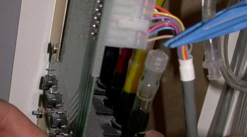
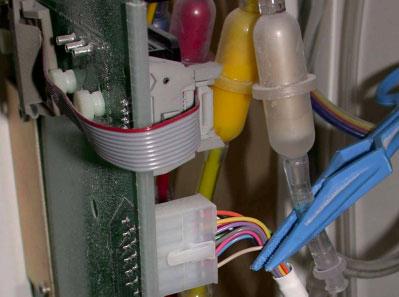
3 Section 1: Remove and Replace the Printer Module 1. Un-park the printer module, turn off power and unplug the Z406T2 before attempting this task. 2. Slide gantry to middle of print area and remove the three screws securing the printer module cover. (See Pictures ) Picture 1.1 Picture Disconnect the PCI ribbon cable, J297, J269, and J448. Refer to #08664 Z406T2 Wiring Procedure for cable locations. (See Picture 1.3) Picture 1.3 J448 Roller Motor J269 Head Card Power Printer to PCI Ribbon Cable J297 Fast Axis Motor Out 3

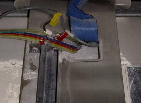
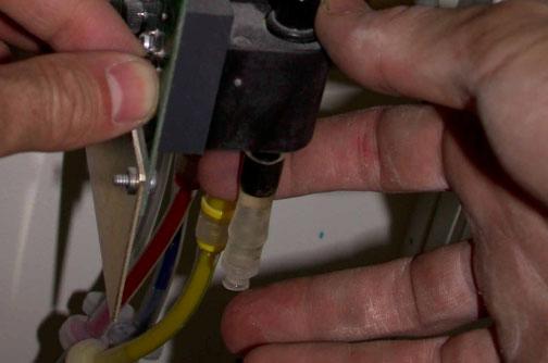
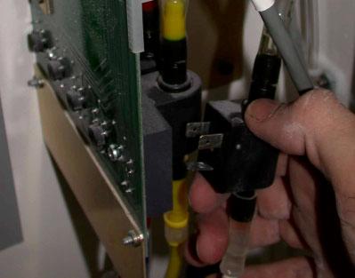
 Waste line Fluid Lines Clamping off fluid lines")


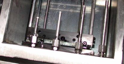
4 4. Using hemostats clamp off the four fluid lines. Hold and twist the luer fittings apart for the fluid lines and the waste line. (See Picture 1.4) Waste line Fluid Lines Clamping off fluid lines Picture Remove the three screws that secure of the printer module to the gantry. (See Pictures ) Picture 1.5 Picture 1.6 Picture Lift up the printer assembly and remove it from the gantry. (See Pictures ) Note: Do not turn the pin shown in (Picture 1.10). Changing the position of the pin will disrupt the Factory alignment of the Gantry. 4

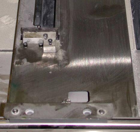

5 Picture 1.8 Picture 1.9 Picture
 Picture 1.11 Picture 1.12 Picture 1.13 2.")
 Tighten the two horizontal screws (on the right of the printer module) first, and the vertical screw (under the manifold). 3.")
 4.")

6 Section 1: Replace the Printer Module To reinsert the Printer Module Assembly follow these steps. 1. Hold the printer module in hand and align the pin on the gantry with the notch on the module. Make sure printer module is not sitting on top of the cables or fluid lines. (See Pictures ) Picture 1.11 Picture 1.12 Picture Install the three screws that secure of the printer module to the gantry. (See Pictures ) Tighten the two horizontal screws (on the right of the printer module) first, and the vertical screw (under the manifold). 3. Reconnect the PCI ribbon cable J297, J269, and J448, Refer to #08664 Z406T2 Wiring Procedure for cable locations. Reconnect fluid supply tubing and waste line. Bleed air after power up as described in the #09504 Z406 User Manual. (See Pictures ) 4. Insert the bottom edge of the Printer Module Cover into the groove at the bottom left side of the Printer Module. Install the three screws securing the printer module cover. (See Pictures ) Note: Now recheck the park position, squeegee interference and duct height adjustment using the following procedures. #08549 Park Position, and the #08608 Z406 Print head Height Compensation Procedure. These procedures are used as a reference to verify things are within specifications. 6
 Picture 2.1 Picture 2.2 3. With the printer module cover removed, disconnect all cables. Refer to #08664 Z406T2 Wiring Procedure for cable locations. (See Picture 2.")
7 Section 2: Remove and Replace the Head Card Assembly 1. Un-park the printer module, turn off power and unplug the Z406T2 before attempting this task. 2. Slide gantry to middle of print area and remove the 3 screws securing the printer module cover. (See Picture ) Picture 2.1 Picture With the printer module cover removed, disconnect all cables. Refer to #08664 Z406T2 Wiring Procedure for cable locations. (See Picture 2.3) J267 Encoder J448 Roller Motor Encoder J273 Head Signal ribbon cable J297 Fast Axis Motor Out J270 Valves J274 Head Power ribbon cable J266 Printer to PCI Ribbon Cable J268 Fast Axis Motor In J269 Head Card power Picture 2.3 7
 Picture 2.")
8 CAUTION Electro static Discharge (ESD) can damage boards. Technicians should always use proper grounding equipment for removal and replacement of PCB cards. 4. Remove the two screws securing the head card to the printer module. Do not remove the four screws securing the card to the backing plate. (See Picture 2.4) Picture 2.4 Location of head card mounting screws 8
 Picture 2.5 2.")
 3 Insert the bottom edge of the Printer Module Cover into the groove at the bottom left side of the Printer Module.")
9 Section 2: Replace the Head Card Assembly To reinsert the Head card PCB Assembly follow these steps. 1. Reinsert the two screws to secure Head Card PCB to printer assembly. (See Picture 2.5) Picture Reconnect all ribbon cables, J297, J267, J268, J269, J270 and J448. Refer to #08664 Z406T2 Wiring Procedure for cable locations. (See Picture 2.3) 3 Insert the bottom edge of the Printer Module Cover into the groove at the bottom left side of the Printer Module. Reinstall the three screws securing the printer module cover. (See Pictures ) 9


 Carriage Card Picture 3.")
10 Section 3: Remove and Replace the Pogo & Carriage Cards 1. Un-park the printer module, turn off power and unplug the Z406T2 before attempting this task. 2. Pull back on the carriage cover latch to open the Carriage Assembly. (The Carriage Cover opens more completely when positioned over the build cylinder with the build piston lowered a few inches.) Lift cover and remove the two screws from the carriage enclosure. Remove the carriage enclosure to expose the Carriage card PCB. (See Pictures ) Carriage Card Picture 3.1 Picture 3.2 Picture Remove the Carriage card PCB by pulling the connectors from the back of the four Pogo boards. (See Picture 3.4) Picture


11 4. Remove the print head in front of the Pogo card being changed. To remove pull print head in an upward motion until the head is free. Next remove the 2 screws securing the Pogo cards to the carriage. Having the screws removed pull the Pogo card in an upward motion and out of the carriage assembly. (See Picture ) Picture 3.6 Picture
 Note: The technician has the option to only replace one pogo card even if it located in the middle. 2. Insert the print head back into the open slot. (See Picture 3.")

12 Section 3: Replace the Pogo & Carriage Cards To reinsert the Pogo card or Carriage card follow these steps. 1. Insert the new Pogo card into the open slot and secure using the two screws. (See Picture 3.7) Note: The technician has the option to only replace one pogo card even if it located in the middle. 2. Insert the print head back into the open slot. (See Picture 3.6) Note: Print heads must be aligned after removal it is recommended that the technician insert Four new print heads after a pogo card is changed. Alignment procedures can be found in the Z406T2 #09518 Users Manual. 3. Holding the Carriage card carefully plug the power and signal flex cables into their sockets. Line up the four connectors (on the stepped side of the PCB) with the connectors on the back of the four Pogo Boards. Spanning the Carriage PCB and the outermost Pogo PCBs with your thumb and forefinger (with both hands one on each side), push the Carriage PCB into the Carriage until the outermost pogo connectors are fully seated. Then ensure that the innermost pogo connectors are fully seated in the same manner. The threaded standoff on the Carriage PCB should line up with the slot in the overhanging flange of the Carriage Enclosure. (See Picture ) Flex cables P6 Power cable P5 Signal cable Picture 3.4 Picture Insert the two screws needed to secure the carriage enclosure and shut the carriage cover. (See Pictures ) 12
 Picture 4.1 Picture 4.2 3.")

13 Section 4: Remove and Replace the Carriage Assembly 1. Un-park the printer module, turn off power and unplug the Z406T2 before attempting this task 2. Slide gantry to middle of print area and remove the three screws securing the printer module cover. (See Picture ) Picture 4.1 Picture Remove the Head Signal & Power ribbon cables from the Head card. Refer to #08664 Z406T2 Wiring Procedure for cable locations. Clamp and disconnect all fluid lines from the top of fluid manifold block routed out towards the Carriage assembly. (See Picture ) J274 Head Power cable Pin 1 at bottom J273 Head Signal cable Pin 1 at bottom Picture 4.3 Picture


14 4. Remove the 4 screws securing the Z406T2 flex cable film, and both fast axis tubing strain relief guides, and the two screws from the fast axis belt mount. (See Picture ) Flex cable film Strain relief Belt mount Picture 4.5 Picture Carefully pull the fluid lines, and flex cables through the fast axis assembly. Laying it out towards the front of machine. Remove the carriage end screw from the fast axis assembly. (See Picture ) Picture 4.7 Picture Lift up the end of the fast axis assembly up from the rail high enough to clear the Carriage assembly. Pull the Carriage assembly towards the front of the machine until it is completely free from the rail. (See Picture ) Picture 4.9 Picture


15 Section 4: Replace the Carriage Assembly To reinsert the Carriage Assembly follow these steps. 1. Lift up the end of the fast axis assembly from the rail high enough to clear the Carriage assembly. Align the Carriage bearing onto the fast axis rail and slide it towards the center of the fast axis assembly. Make sure the fluid lines and ribbon cables are free from being snagged. Install the end screw back onto the fast axis assembly. (See Picture ) Picture 4.11 Picture Carefully lay the ribbon cable and fluid lines along the inside wall of the fast axis assembly. Install the four screws needed to secure the fast axis tubing strain relief brackets. Make sure to align the Z406T2 flex cable film at the opening with the bracket on top. Before tightening, ensure there is enough slack in the cables and tubes for the full range of motion for the carriage. (Picture ) Picture 4.13 Picture
16 3. Install the 2 screws for the fast axis belt mount to the Carriage assembly. Reconnect all fluid lines. (See Picture ) Picture 4.15 Picture Reconnect the J273 Head Signal, and J274 Power ribbon cables, Refer to #08664 Z406T2 Wiring Procedure for cable locations. (See Picture 4.3) 5. Slide gantry to middle of print area and insert the bottom edge of the Printer Module Cover into the groove at the bottom left side of the Printer Module. Reinstall the three screws securing the printer module cover. (See Picture ) 6. Never attempt to print without referring to the Z406T2 User manual for instructions on purging air from the lines. 16


 Picture 5.1 Picture 5.2 3.")

17 Section 5: Remove and Replace the Gantry Manifold Assembly 1. Un-park the printer module, turn off power and unplug the Z406T2 before attempting this task. 2. Slide gantry to middle of print area and remove the three screws securing the printer module cover. (See Picture ) Picture 5.1 Picture Remove the J1 cable from the rear of the manifold PCB card. Clamp and disconnect all fluid lines from the fluid manifold block. (See Picture ) Picture 5.3 Picture


 Picture 5.")
18 4. Remove the two screws securing the Gantry Manifold Block to the fast axis assembly. (See Pictures ) Picture 5.5 Picture 5.6 Picture
19 Section 5: Replace the Gantry Manifold Assembly To reinsert the Gantry Manifold Assembly follow these steps. 1. Install the two screws into the Gantry Manifold Assembly needed to secure it to the fast axis assembly. (See Pictures ) 2. Install the J1 cable, and reconnect all the fluid lines for the manifold block. (See Picture ) 3. Insert the bottom edge of the Printer Module Cover into the groove at the bottom left side of the Printer Module. Reinstall the three screws securing the printer module cover. (See Picture ) 4. Never attempt to print without referring to the Z406T2 User manual for instructions on purging air from the lines. 19
20 Section 6: Remove & Replace the Flex Cables 1. Un-park the printer module, turn off power and unplug the Z406T2 before attempting this task. 2. Slide gantry to middle of print area and remove the three screws securing the printer module cover. (See Picture ) Picture 6.1 Picture Refer to #08664 Z406T2 Wiring Procedure for all cable locations and #08639 Carriage Tubing and Cable Routing Procedure. Refer to steps 3-6 of the Remove and Replace Carriage Assembly section. 20


 Picture 7.1 Picture 7.2 3.")


21 Section 7: Remove and Replace the Septum 1. Un-park the printer module, turn off power and unplug the Z406T2 before attempting this task. 2. Slide gantry to middle of print area and pull down on the carriage cover latch to open the Carriage Assembly. (See Pictures ) Picture 7.1 Picture Remove the print head of the septum being changed. To remove pull print head in an upward motion until the head is free. Once the septum is exposed use the Socket, 5/16 12-Pt deep ¼ Sq Drive connected to the 2.5 in lb. Torque wrench provided in the toolkit kit to remove the bad septum. (See Pictures ) Picture 7.3 Picture 7.4 Picture

 Picture 7.")


22 Section 7: Replace the Septum To reinsert the Septum follow these steps. 1. Install the new septum into the Carriage Assembly. Turn the septum by hand to start the threads. After it is started use the Socket, 5/16 12-Pt deep, and a ¼ Sq drive connected to the 2.5 in lb. Torque wrench provided in the toolkit kit to tighten the new septum. (See Pictures ) Picture 7.6 Picture Reinsert the print head back into the opening. Next, pull down on the carriage cover latch to lock the Carriage Assembly cover shut. (See Picture ) Note: Print heads must be aligned after removal it is recommended that the technician insert four new print heads after a pogo card is changed. Alignment procedures can be found in the #09518 Z406T2 Users Manual. 3. Never attempt to print without referring to the Z406T2 User manual for instructions on purging air from the lines. 22


 Idler Pulley Tensioner Bracket Pressing the Idler Pulley Tensioner Bracket Drive pulley")

23 Section 8: Remove & Replace Fast Axis Idler Pulley Assembly 1. Loosen the Idler Pulley Tensioner Bracket screw. Press the Idler Pulley Tensioner Bracket inwards to compress the spring. While holding the Idler Pulley Tensioner Bracket inwards the timing belt should slacken up over the drive pulley. (See Pictures ) Idler Pulley Tensioner Bracket Pressing the Idler Pulley Tensioner Bracket Drive pulley Picture 8.1 Picture 8.2 Picture Once the Idler Pulley Tensioner Bracket is compressed the belt will slip over the drive pulley for removal of the entire Fast Axis Idler Pulley Assembly. The Idler Pulley Tensioner Bracket will now be free of the drive pulley of the Fast Axis Motor. (Picture 8.4) Picture

 Push here and hold to compress spring Tensioner bracket screw Picture 8.5 Picture 8.6 2.")
 Pull belt over pulley Picture 8.7 3.")
24 Section 8: Replace Fast Axis Idler Pulley Assembly To reinsert the Fast Axis Idler Pulley Assembly follow these steps. 1. Slide the Idler Pulley Assembly horizontally into slot on Fast Axis Extrusion. With index finger, press in on leftmost vertical wall of the Idler Pulley Tensioner Bracket to further compress spring. (See Pictures ) Push here and hold to compress spring Tensioner bracket screw Picture 8.5 Picture While holding the spring compressed, stretch timing belt over drive pulley of the Fast Axis Motor Assembly. When the belt is in place, let go of the Idler Pulley Tensioner Bracket. (See Picture 8.7) Pull belt over pulley Picture Tighten the screw in Idler Pulley Tensioner Bracket completely. The spring will automatically tension the timing belt as you tighten the screw. This screw then locks the bracket into position Refer to #08667 Z406T2 Belt Tension Procedure document for any questions. 24


 Picture 9.1 Picture 9.2 2.")


25 Section 9: Remove & Replace Fast Axis Motor Assembly 1. Having the Fast Axis Idler Pulley Assembly is removed. The pulley for the Fast Axis Motor Assembly should have the belt removed. (Picture ) Picture 9.1 Picture Remove the cable J267 on the Headcard. Refer to #08664 Z406T2 Wiring Procedure for all cable locations. Remove the four screws securing the Fast Axis Motor Assembly to the Fast Axis Assembly. (See Pictures ) Screw locations for Fast Axis motor Picture 9.3 Picture 9.4 Picture
26 Section 9: Replace Fast Axis Motor Assembly To reinsert the Fast Axis Motor Assembly follow these steps. 1. Install the four screws securing the Fast Axis Motor Assembly to the Fast Axis Assembly. (See Picture 9.6) Picture Reinstall the cable into J267 on the Headcard. 26


27 Section 10: Remove & Replace Top Cover Interlock Switch 1. Un-park the printer module, turn off power and unplug the Z406T2 before attempting this task 2. Remove the eight screws securing the Z406T2 rear cover and locate the Top cover interlock switch and cable assembly. (See Pictures ) Top cover interlock switch Picture 10.1 Picture Remove the two nuts securing the Top cover interlock switch and cable assembly. (See Pictures ) Picture 10.3 Picture


28 4. Remove the cable assembly for the Top cover interlock switch. This will require the technician to cut a few wire ties and remove the plastic channeling for the cable routing. Refer to #08664 Z406T2 Wiring Procedure for all cable locations. (See Picture 10.5) Picture Remove the mounting plate from the Top cover interlock switch and cable assembly (#05593). (See Pictures ) Picture 10.6 Picture
29 Section 10: Replace Top Cover Interlock Switch To reinsert the Top cover interlock switch and cable assembly follow these steps. 1. Install the mounting plate onto the new Top cover interlock switch and cable assembly (#05593). (See Pictures ) 2. Install the cable assembly for the Top cover interlock switch. This will require the technician to replace a few wire ties and reinstall the plastic channeling for the cable routing. Refer to #08664 Z406T2 Wiring Procedure for all cable locations. (See Pictures 10.5) 3. Reinstall the two nuts securing the Top cover interlock switch and cable assembly. (See Pictures ) 4. Reinstall the eight screws securing the Z406T2 rear cover. (See Pictures ) 29
30 Section 11: Remove & Replace the Interface PCB card 1. Un-park the printer module, turn off power and unplug the Z406T2 before attempting this task 2. Remove the eight screws securing the Z406T2 rear cover and locate the Interface PCB card. (See Picture 11.1) Interface PCB card Picture 11.1 CAUTION Electro static Discharge (ESD) can damage boards. Technicians should always use proper grounding equipment for removal and replacement of PCB cards. 30
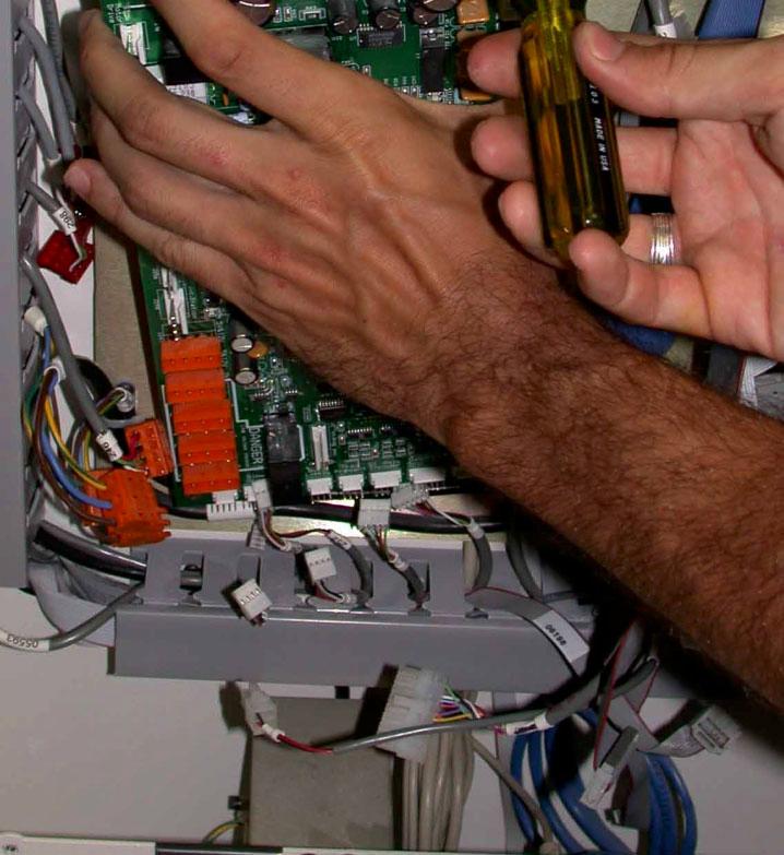
31 3. Remove the cables, J239, J240, J219, J227, J303, J211, J245, J208, J263, J250, J251, J254, J258, J262, J253, J241, J242, J252, J265, J298, and J238. Refer to #08664 Z406T2 Wiring Procedure for all cable locations. Remove the six screws securing the Interface PCB card to the electronics panel. See the negative call out for removal of two screws circled in yellow. (See Pictures ) Picture 11.2 Do not loosen or remove these screws. Loosing screws causes serious damage to the PCB board. 31

32 Picture
33 Section 11: Replace the Interface PCB card To reinsert the Interface PCB Card follow these steps. 1. Install the six screws securing the new Interface PCB Card mounting plate onto the electronics panel. (See Pictures 11.3) 2. Reinstall the cables, J239, J240, J219, J227, J303, J211, J245, J208, J263, J250, J251, J254, J258, J262, J253, J241, J242, J252, J265, J298, and J238. Refer to #08664 Z406T2 Wiring Procedure for all cable locations. Reinstall the cable guide covers if they were removed for this activity. 3. Reinstall the eight screws securing the Z406T2 rear cover. (See Pictures11.1) 33


34 Section 12: Remove & Replace the PCI PCB card 1. Un-park the printer module, turn off power and unplug the Z406T2 before attempting this task 2. Remove the eight screws securing the Z406T2 rear cover and locate the PCI PCB card. (See Picture 12.1) PCI PCB card Picture Remove the ribbon cables, J230, J229, J231, J232, J233, and J236. Refer to #08664 Z406T2 Wiring Procedure for all cable locations. Remove the two screws securing the PCI PCB card into the support bracket on the electronics panel. (See Picture 12.2) Picture


35 CAUTION Electro static Discharge (ESD) can damage boards. Technicians should always use proper grounding equipment for removal and replacement of PCB cards. 4. Using both hands grip the PCI card from the top and bottom. Pull the PCI PCB card out of PCI slot on motherboard. (See Picture 12.3) Picture
36 Section 12: Replace the PCI PCB card To reinsert the PCI PCB Card follow these steps. 1. Using both hands grip the PCI card from the top and bottom. Pushing the PCI PCB card into the first PCI slot on far left side of the motherboard. (See Picture 12.3) 2. Install the two screws securing the PCI PCB card into the support bracket on the electronics panel. 3. Reinsert the ribbon cables, J230, J229, J231, J232, J233, and J236. Refer to #08664 Z406T2 Wiring Procedure for all cable locations. (See Picture 12.2) 4. Reinstall the eight screws securing the Z406T2 rear cover. (See Picture 12.1) 36


37 Section 13: Remove & Replace the Control Panel 1. Turn off power and unplug the Z406T2 before attempting this task. 2. Remove the four screws securing the control panel to the 406T2. (See Picture 13.1) Control panel Screw locations Picture Having removed the four screws securing the control panel, unplug the ribbon cable from the rear of panel and remove. (See Pictures ) Picture 13.2 Picture 13.3 Picture
38 Section 13: Replace the Control Panel To reinsert the Control Panel follow these steps. 1. Plug the ribbon cable from the rear of panel and set the panel in place on the machine. (See Pictures ) 2. Install the four screws securing the control panel to the 406T2. (See Pictures 13.1) 38
 Picture 14.1 3. Remove the three adjustment screws securing the Service Station plate to the Service Station Assembly.")
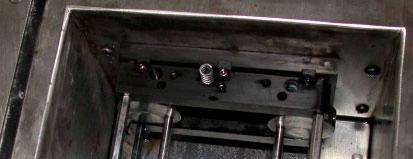
39 Section 14: Remove & Replace the Service Station 1. Un-park the printer module, turn off power and unplug the Z406T2 before attempting this task. 2. Remove the Service Station cover plate from the top deck. (See Picture 14.1) Picture Remove the three adjustment screws securing the Service Station plate to the Service Station Assembly. Carefully remove the TOP plate out of the Service Station, and remove the three compression springs at the base of the plate. (See Pictures ) NOTE: Do not at any time during this removal step attempt to adjust these jackscrews. If jackscrews are moved, the technician must complete the #08649 Z406T2 Service Station Alignment procedure. 39


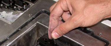
40 Picture 14.2 Picture 14.3 Picture 14.4 Picture


 Picture 14.")


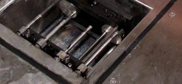
41 4. Remove six of the eight screws securing the Service Station to the top deck. (See Pictures ) Picture 14.6 Picture Grasp the exposed motor rods and remove the remaining screws. The Service Station can be removed. (See Pictures ) Picture 14.8 Picture


 Picture 14.10 Picture 14.")


42 6. Remove the cables, Refer to #08664 Z406T2 Wiring Procedure for all cable locations. Disconnect the quick disconnect fitting for the waste line and the luer fitting for the squirters. (See Pictures ) Picture Picture Picture Grasp the Service Station, and turn sideways to allow for easy removal. Pull up and out of the Top deck. (See Picture 14.13) Picture
43 Section 14: Replace the Service Station To reinsert the Service Station Assembly follow these steps. 1. Grasp the Service Station at an angle and insert into the top deck. (See Picture 14.13) 2. Reinsert the cables, Refer to #08664 Z406T2 Wiring Procedure for all cable locations. Reconnect the quick disconnect fitting for the waste line and the luer fitting for the squirters. (See Pictures ) 3. Reinsert the eight screws securing the Service Station to the top deck. Hold the Service Station Assembly with a free hand to prevent it from falling into the machine. (See Pictures ) 4. Reinsert the three compression springs back into place under the TOP plate. Seat the TOP plate in position inside the Service Station Assembly. Reinsert the three adjustment screws and tighten down cover plate. (See Pictures ) 5. Reinstall the Service Station cover plate to top deck. (See Picture 14.1) Note: Now recheck the park position, squeegee interference and duct height adjustment using the following procedures. #08549 Park Position, and the #08608 Z406 Print head Height Compensation Procedure. These procedures are used as a reference to verify things are within specifications. 43


44 Section 15: Remove & Replace the Service Station PC Card 1. The technician must complete Section 14 Service Station removal before beginning to remove the Service Station PCB card. 2. Lay the Service Station on a table to allow for easy removal of the Service Station PCB card. Remove the motor cable from pin J201. Next, locate the hole on the magnetic collar for removal. It may be necessary to rotate the gears by hand to turn the magnetic collar. (See Pictures ) Picture 15.1 Picture 15.2 Picture 15.3 Picture

 Picture 15.5 Picture 15.")
45 3. Remove the four screws securing the Service Station PCB card to the service station motor plate. (See Pictures ) Picture 15.5 Picture 15.6 Picture
46 Section 15: Replace the Service Station PC Card To reinsert the Service Station PCB Card follow these steps. 1. Reinsert the four screws securing the Service Station PCB card to the service station motor plate. (See Pictures ) 2. Reinstall the magnetic collar back onto the PCB card. Apply a drop of LOCTITE #7649 Primer and LOCTITE #222 thread locker then tighten the setscrew into the collar. (See Picture 15.8) Picture Plug in the motor cable to pin J201. (See Picture 15.1) Note: Now recheck the park position, squeegee interference and duct height adjustment using the following procedures. #08549 Park Position, and the #08608 Z406 Printhead Height Compensation Procedure. These procedures are used as a reference to verify things are within specifications. 46


47 Section 16: Remove & Replace the Service Station Motor Assembly 1. The technician must complete Section 14 & 15 Service Station and PCB card removal before beginning to remove the Service Station Motor Assembly 2. Remove the four screws securing the Service Station Motor Assembly to the service station. (See Pictures ) Picture 16.1 Picture 16.2 Picture 16.3 Section 16: Remove & Replace the Service Station Motor Assembly To reinsert the Service Station Motor Assembly follow these steps. 1. Ensure proper engagement between the gears of the Service Station and the motor shaft. 2. Reinsert the four screws securing the Service Station Motor Assembly to the service station. (See Pictures ) 47
48 Section 17: Remove & Replace the Service Station Gears 1. The technician must complete Section 14 thru 16 before beginning to remove the Service Station Motor Gears. 2. Refer to the 406T2 Service Station Assembly Drawing #04408 to perform any gear replacements or to repair the cams. 48
49 Section 18: Remove & Replace Service Station Squirters 1. Un-park the printer module for the Z406T2 before attempting this task. (See Picture 18.1) Picture Remove the Service Station cover plate from the top deck to expose the squeegee squirters. (See Pictures ) Picture 18.2 Picture

50 3. Using an open end 3/8 wrench remove the squeegee squirt tube turning in a counterclockwise motion until the nut is free from the compression fitting on manifold. (See Pictures 18.4) Picture 18.4 Section 18: Replace & Aim Service Station Squirters To reinsert the Service Station Squirter tube follow these steps. 1. Reinsert the new squirt tube and tighten in a clockwise motion using an open-end 3/8 wrench. Tighten until the nut is compresses with the fitting on manifold. Always use a new compression fitting for every removal of tube. (See Pictures 18.4) 2. Alignment of squeegee squirt tube must be done by technician after it is installed back into the Service station. Squeegee s must be rotated and the squeegee blocks adjusted to optimize print head cleaning. The goal is to aim the streams of fluid to hit the crest (sharp edge) of each squeegee and as close to the near corner of small squeegee as possible. Refer to the #08550 Squeegee Squirter Adjustment Procedure for this step. 3. Replace the Service Station cover plate on the top deck of the 406T2. (See Pictures ) 50

51 Section 18: Clean Service Station Squirters To clean the Service Station Squirter tubes follow these steps. 1 Periodically, the wash fluid flowing out of the squeegee squirters may converge/diverge. This can be caused by a clog in the holes and contamination of the wash fluid. To clean out the holes, use the jet-cleaning tool (part number 04241) provided in the toolkit that accompanied the printer. 2. Remove the squirter cap using a hex key tool #3/32 found in the toolbox, and set the cap aside. (See Picture 18.5) Picture 18.5 Hex Key 3/32 Squirter Cap 3. Insert the fine metal piece from the jet-cleaning tool into the two holes on the squirter to unclog the holes of debris. Perform a squirt operation from a keyboard plugged into the back of the Z406. Push (ctrl s) to flush any debris out the end of the tube, and replace squirter cap. Realign squirters with the squeegees. Refer to the #08550 Squeegee Squirter Adjustment Procedure for this step. 51
52 Section 19: Remove & Replace Service Station Squeegees 1. Un-park the printer module for the Z406T2 before attempting this task. (See Picture 19.1) Picture Remove the Service Station cover plate from the top deck to expose the squeegees. (See Pictures ) Picture 19.2 Picture


53 NOTE: Do not at any time during this removal step attempt any adjustments to the squeegee block screws. If screws are moved, the technician must complete the #08550 Squeegee Squirter Adjustment Procedure. 3. Using a small flat tip screwdriver remove the metal clip securing the squeegee to the service station plate. Remove the squeegee. (See Pictures ) Squeegee bracket Picture 19.4 Picture 19.5 Picture 19.6 Picture 19.7 Picture
54 Section 19: Replace Service Station Squeegees To reinsert the Service Station Squeegee follow these steps. 1. Reinsert the new Squeegee onto the service station plate and secure using the metal clip. (See Pictures ) 2. Perform a squirt operation to ensure proper alignment was maintained if not perform procedure #08550 Squeegee Squirter Adjustment Procedure. 3. Reinstall the Service Station cover plate to the top deck of the 406T2. (See Pictures ) 54


55 Section 20: Remove & Replace Service Parking Caps 1. Un-park the printer module, turn off power and unplug the Z406T2 before attempting this task. (See Picture 20.1) Picture Remove the Service Station cover plate from the top deck to expose the squeegees. (See Pictures ) Picture 20.2 Picture


56 3. Lift the leg clipping the HP cap to the spring cap-mounting block inside the Service Station Assembly. Make sure to remove the spring and replace with new one. (See Pictures ) Picture 20.4 Picture 20.5 Picture 20.6 Picture 20.7 Note: Now recheck the park position, squeegee interference and duct height adjustment using the following procedures. #08549 Park Position, and the #08608 Z406 Print head Height Compensation Procedure. These procedures are used as a reference to verify things are within specifications. 56
57 Section 20: Replace Service Parking Caps To reinsert the Service Station Parking Cap follow these steps. 1. Reinsert the new Parking Cap spring onto the cap-mounting block. (See Picture 20.7) 2. Reinstall the new Parking Cap onto the cap-mounting block. (See Picture 20.6) 3. Reinstall the Service Station cover plate onto the top deck of the 406T2. (See Picture 20.2) Section 21: Remove & Replace Pump Assembly 57
58 1. Un-park the printer module, turn off power and unplug the Z406T2 before attempting this task. (See Picture 21.1) Picture Remove the eight screws securing the Z406T2 rear cover and locate the Pump Assembly. (See Picture ) Pump Assembly Picture 21.1 Picture Clamp the fluid line on both ends of the Pump Assembly. Remove the luer fittings for each ends of the pump. (See Pictures ) 58


59 Picture 21.3 Picture Turn the thumbscrew in a counterclockwise motion to unscrew and then pull the pump to unplug it from the Pump PCB Assembly. (See Pictures ) Picture 21.5 Picture
 2. Reinstall the luer fittings for each end of pump and remove the clamps. (See Pictures 21.4-21.3) 3. Reinstall the eight screws securing the Z406T2 rear cover.")
60 Picture 21.7 Section 21: Remove & Replace Pump Assembly To reinsert the Pump Assembly follow these steps. 1. Plug pump into Pump PCB Assembly and reinsert thumbscrew in a clockwise motion. (See Pictures ) 2. Reinstall the luer fittings for each end of pump and remove the clamps. (See Pictures ) 3. Reinstall the eight screws securing the Z406T2 rear cover. (See Picture ) 4. Never attempt to print without referring to the Z406T2 User manual for instructions on purging air from the lines. 60
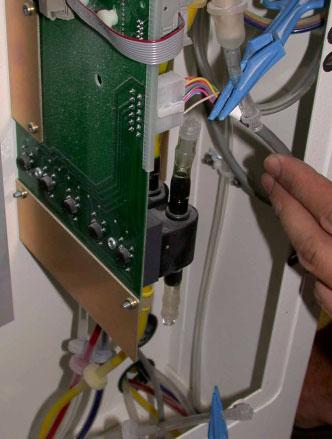
61 Section 22: Remove & Replace Pressure Switch Assembly 1. Un-park the printer module, turn off power and unplug the Z406T2 before attempting this task. this task. (See Picture 22.1) Picture Remove the eight screws securing the Z406T2 rear cover and locate the Pressure Switch Assembly. (See Picture ) Pressure Switch Assembly Picture 22.1 Picture


 Picture 22.3 Picture 22.")


62 3. Clamp the fluid line for the Pressure Switch Assembly. Remove the luer fittings for Pressure Switch. (See Pictures ) Picture 22.3 Picture Turn the two thumbscrews in a counterclockwise motion to unscrew and then pull the Pressure Switch to unplug it from the Pump PCB Assembly. (See Pictures ) Picture 22.5 Picture
63 Section 22: Replace Pressure Switch Assembly To reinsert the Pressure Switch Assembly follow these steps. 1. Plug the Pressure Switch into Pump PCB Assembly and reinsert the two thumbscrews in a clockwise motion. (See Pictures 22.5) 2. Reinstall the luer fittings for each end of Pressure Switch and remove the clamps. (See Pictures ) 3. Turn on the printer and bleed air and USE A PRESSURE GAUGE TO confirm pressure switch is properly adjusted to provide 3 psi at the septum. (TURN THE SET SCREW ON THE SWITCH TO ADJUST THE PRESSURE TO 3 PSI) 4. Reinstall the eight screws securing the Z406T2 rear cover. (See Picture ) 5. Never attempt to print without referring to the Z406T2 User manual for instructions on purging air from the lines. 63
 Picture 23.1 2. Remove the eight screws securing the Z406T2 rear cover and locate the Filter Assembly. (See Picture 23.1-23.2) Filter Assembly Picture 23.1 Picture 23.")
64 Section 23: Remove & Replace Filter Assembly 1. Un-park the printer module, turn off power and unplug the Z406T2 before attempting this task. this task. (See Picture 23.1) Picture Remove the eight screws securing the Z406T2 rear cover and locate the Filter Assembly. (See Picture ) Filter Assembly Picture 23.1 Picture

 Female Luer Filter should be installed with arrows facing")
65 3. Clamp the fluid lines for the Filter Assembly. Disconnect the luer fittings on both ends of filter and remove. (See Pictures ) Female Luer Filter should be installed with arrows facing upwards. Male Luer Picture 23.3 Picture
66 Section 23: Replace Filter Assembly To reinsert the Filter Assembly follow these steps. 1. Reinstall the filter in the correct orientation. Secure the luer fittings on both ends of filter. (See Pictures 23.4) 2. Unclamp the fluid lines on either end of the filter. (See Pictures 23.3) 3. Reinstall the eight screws securing the Z406T2 rear cover. (See Picture ) 4. Never attempt to print without referring to the Z406T2 User manual for instructions on purging air from the lines. 66


67 Section 24: Remove & Replace Bottle Holder Assembly 1. Open the Z406T2 front doors and locate the Bottle Holder Assembly. (See Picture 24.1) Picture 24.1 Bottle Holder Assembly 2. Remove the four hold down screws from the Bottle Holder Assembly two on each side of the tray. (See Picture ) Picture 24.2 Picture


68 3. Remove the Bottle Holder Assembly from the 406T2 pulling tray forward and tilting it towards the technician lifting it up and out. Sit the tray outside the machine allowing the tubing to lay flat. (See Picture ) Picture 24.4 Picture 24.5 Screw Locations Picture 24.6 Picture
 3.")
69 Section 24: Replace Bottle Holder Assembly To reinsert the Bottle Holder Assembly follow these steps. 1. Loosely install the screws for the Bottle Holder Assembly into the body of the 406T2. 2. Align the Bottle Holder Assembly with the four screws inside the base of the 406T2. Slide the bottle holder toward the front of the machine to engage the screws. (See Picture ) 3. Tighten the four hold down screws securing the Bottle Holder Assembly two on each side of the tray. (See Picture ) 4. Shut off and unplug the printer. Remove the eight screws in rear cover and remove. Pull the extra cable and tubing through the rear of the machine and loop in the bottom corner. (See Picture 24.8) Picture Reinstall the eight screws securing the rear cover of the printer close the front doors for the 406T2. (See Picture 24.1) 6. Never attempt to print without referring to the Z406T2 User manual for instructions on purging air from the lines. 69
 Waste Bottle Assembly Picture 25.1 2. Disconnect the plug for the float switch, and the quick disconnect from the Waste Bottle Assembly.")
70 Section 25: Remove & Replace Waste Bottle Assembly 1. Open the Z406T2 front doors and locate the Waste Bottle Assembly. (See Picture 25.1) Waste Bottle Assembly Picture Disconnect the plug for the float switch, and the quick disconnect from the Waste Bottle Assembly. (See Picture ) 70


 Picture 25.")
71 Picture 25.2 Picture Remove the waste bottle from the support bracket, and loosen the three screws securing the bracket assembly to 406T2 base freeing the bracket for removal. (See Picture ) Picture 25.4 Picture
72 Section 25: Replace the Waste Bottle Assembly To reinsert the Waste Bottle Assembly follow these steps. 1. Install the screws for the waste bottle bracket assembly into the body of the 406T2. Align the bracket with the three screws inside the base of the 406T2 and tighten down. (See Picture 25.6) 2. Insert the waste bottle into the support bracket reconnecting the quick connect for the Waste Bottle, and plug for float switch. (See Picture ) 3. Close the front doors for the 406T2. (See Picture 25.1) 72
73 Section 26: Remove & Replace Slow Axis Motor Assembly 1. Un-park the printer module, turn off power and unplug the Z406T2 before attempting this task. this task. (See Picture 26.1) Picture Remove the eight screws securing the Z406T2 rear cover and locate the Slow Axis Motor. (See Picture 26.2) Slow Axis Motor Picture


74 3. Remove the Slow Axis Belt. Refer to #08667 Z406T2 Belt Tension Procedure document for any questions. Remove all cable connections from motor. Refer to #08664 Z406T2 Wiring Procedure for all cable locations. (See Picture 26.3) Slow Axis Belt Picture Remove the six nuts securing the Slow Axis Motor to the 406T2 frame. (See Picture 26.4) Slow Axis Motor Picture
75 Section 26: Replace the Slow Axis Motor Assembly To reinsert the Slow Axis Motor Assembly follow these steps. 1. Install the six nuts securing the Slow Axis Motor to the 406T2 frame. (See Picture 26.4) 2. Reconnect the Slow Axis Belt. Refer to #08667 Z406T2 Belt Tension Procedure document. Reconnect all cable connections from motor. Refer to #08664 Z406T2 Wiring Procedure for all cable locations. (See Picture 26.3) 3. Install the eight screws securing the Z406T2 rear cover. (See Picture 26.2) 75


76 Section 27: Remove & Replace the Build or Feed Piston 1. Always ensure the printer is parked, using the control panel ensure piston is in the middle of box, turn off power and unplug the Z406T2 before attempting this task. 2. The technician must complete the removal of the Bottle Holder Assembly covered in Section 24 of this manual. Once this assembly is out the bottom of the pistons and motors are visible. 3. Push the feed piston down to center of box. Remove the four screws securing the lower plate to piston shafts and lead screw. Each screw has two parts for a total of eight, and the plate has four on each side. (See Pictures ) Picture 27.1 Picture 27.2 Picture


77 4. Using your hand pull up on the piston shafts, and separate the two pieces. Pushing upwards the piston shaft must come out of box. (See Picture ) Picture 27.4 Picture 27.5 Picture 27.6 Picture

 Pictures 27.8 2.")
78 Section 27: Replace the Build or Feed Piston To reinsert the Build or Feed Piston follow these steps. 1. Lubricate the shafts using the lithium grease from toolkit before aligning the piston inside the box. Slowly push down on the piston plate until the shafts meet with the lower plate. Guide into the holes in the lower plate until bottom of shaft is even with the shafts base. (See Pictures 27.8) Pictures Install the eight screws back into the lower plate inserting the four corners first followed by the remaining four screws. 3. Reinstall the Bottle Holder Assembly covered in Section 24 of this manual. 78


79 Section 28: Remove & Replace the Build or Feed Piston Seal 1. Ensure the printer is parked, and turn off power and unplug the Z406T2 before attempting this task. this task. 2. The technician must complete the removal of the Bottle Holder Assembly covered in Sections 24 and 27 of this manual. 3. The piston must be outside of build box for the removal of the two screws securing the Down sensor flag to plate. Remove the eight screws attaching the piston plates with the Piston Seal in the middle. Lift plate to expose the felt Piston Seal. (See Pictures ) Pictures 28.1 Pictures
80 Pictures Remove the felt Piston Seal by lifting up and off the shafts. (See Pictures 28.4) Felt Piston Seal Pictures The Piston Energizer Seal may also be removed at this point. This seal sits in s groove around the main piston plate. Remove by pulling off the seal from around plate. This ENERGIZER can be changed on it s own or with the Piston Seal. (See Pictures 28.5) Piston Energizer Seal Pictures
81 Section 28: Replace the Build or Feed Piston Seal To reinsert the Build or Feed Piston Seal follow these steps. 1. Install the felt Piston Seal by guiding it down the piston shafts, and seating it on the bottom piston plate. (See Pictures 28.4) 2. Install the eight screws attaching the piston plates with the Piston Seal in the middle. Install the two screws for the Down Sensor Flag. (See Pictures ) 3. The piston must be reinstalled into the box. Technician must complete Sections 27 and 24 to complete task. 81


82 Section 29: Remove & Replace the Build or Feed Piston Motor 1. Ensure the printer is parked, turn off power, and unplug the Z406T2 before attempting this task. this task. 2. The technician must complete the removal of the Bottle Holder Assembly covered in Sections 24 and 27 of this manual. 3. The piston must be outside of build box for the removal of the four Piston Motor nuts located inside the box. Remove the four nuts securing the motor to bottom of box using a nut driver. (See Pictures 29.1) Pictures


83 4. Remove the four screws securing the motor to bottom of box, and unplug all cables for motor. (See Pictures ) Picture 29.2 Picture Remove the nut securing the lower plate to the lead screw. (See Pictures ) Pictures 29.4 Pictures
 Picture 29.7 2.")

84 Section 29: Replace the Build or Feed Piston Motor To reinsert the Build or Feed Piston Motor follow these steps. 1. Apply a line of lithium grease to lead screw. (See Pictures ) Picture Install the nut securing the lower plate to the lead screw. (See Pictures ) 3. Install the four Piston Motor screws located on the underside of the box, and plug in all cables for motor. (See Pictures ) 4. Install the four Piston Motor nuts located inside the box. (See Pictures 29.1) 84
Removing and Replacing the Y-truck
 Service Documentation Removing and Replacing the Y-truck To remove and replace the Y-truck you will need the following tools: 4mm Allen wrench 12mm stamped flat wrench #2 Phillips screwdriver (magnetic
ABM International, Inc. Navigator Assembly Manual
 ABM International, Inc. 1 1.0: Parts List Tablet (Qty. 1) Tablet mount (Qty. 1) NOTE: Mount may appear and operate different then image below Control Box (Qty. 1) Motor Power Supply (Qty. 1) 2 X-axis motor
3.2.3 Rear Door Window and Quarter Window Carrier Assembly
 Tighten all bolts. Tighten bolts marked -1- and -2- in specified sequence. Tightening torque: 8 Nm Remaining bolts can be tightened in any sequence. Insert door window -3- through window recess without
TorqueMaster Replacement Spring
 TorqueMaster Replacement Spring Installation Instructions NOTE: Use these installation instructions in conjunction with the TorqueMaster Repair / Replacement Spring Program literature. Copyright 999 Wayne-Dalton
Print Head Installation Guide
 Print Head Installation Guide MCS Raptor 6 (MCS Eagle AMS Software) is copyright of MCS Incorporated. 2015 MCS Incorporated. 1 Contents Tools... 4 Warnings... 4 Introduction... 4 Section One - Pillar Installation...
7878 K940. Checkpoint Antenna. Kit Instructions. Issue B
 7878 K940 Checkpoint Antenna Kit Instructions Issue B Revision Record Issue Date Remarks A July 7, 2009 First issue B Nov2013 Revised the Checkpoint installation procedures for 7878 and 7874 scanners Added
REPAIR INSTRUCTIONS. Cat. No Cat. No MILWAUKEE ELECTRIC TOOL CORPORATION. SDS Max Demolition Hammer. SDS Max Rotary Hammer
 Cat. No. 9-0 SDS Max Demolition Hammer Cat. No. -0 SDS Max Rotary Hammer MILWAUKEE ELECTRIC TOOL CORPORATION W. LISBON ROAD BROOKFIELD, WISCONSIN 00-0 8-9-0 d 000 8-9-0 d Special Tools Require Forcing
INVENT3D Printer Kit Disassembly Instructions
 INVENT3D Printer Kit Disassembly Instructions Version 6 AST2 10/26/16 1 I. General Disassembly Instructions Use the case layer drawings to ensure that components are stored in the appropriate location
RTI TECHNOLOGIES, INC.
 RTI TECHNOLOGIES, INC. BRC500 & BRC550 Arbor/Spindle Mechanism Adjustment & Service Technical Instructions The arbor/spindle mechanism of the BRC500/550 is designed to be robust for long life. Occasionally
Band-Master ATS Nano Pneumatic Banding Tool Operating Instructions
 Band-Master ATS 601-118 Nano Pneumatic Banding Tool CONTENTS 601-118 Overview... 3 Safety.... 5 Initial Tool Set-up... 5 Regulator assembly mounting... 5 Attach tool head to regulator.... 6 Operating instructions...
Electric Skein Winder
 Electric Skein Winder Assembly and Use Package Contents 1 - Triangular Body (w/ motor) 1 - Cross Arm 1 - Left Foot (w/ yarn guide) 1 - Right Foot 1 - Adjustable Finger (w/ yarn clip) 3 - Adjustable Fingers
The Bowflex Revolution XP Home Gym Assembly Instructions. P/N: Rev ( /0 )
") P/N: 001-7057 Rev ( /0 ) The Bowflex Revolution XP Home Gym Assembly Instructions 2 Table of Contents Before You Start... 2 Tools You Will Need / Hardware Contents... 3 Box Contents... 6 Assembling Your
P/N: 001-7057 Rev ( /0 ) The Bowflex Revolution XP Home Gym Assembly Instructions 2 Table of Contents Before You Start... 2 Tools You Will Need / Hardware Contents... 3 Box Contents... 6 Assembling Your
Removing outter components
 Y Axis Motor Replacement Replacing the Y axis motor is a process that requires the individual to be somewhat mechanically inclined and can follow detailed instructions. If any of the following steps are
Removing the Z-Axis lead screw
 Page 1 of 8 TITLE: Sabre Z-Axis Lead Screw Replacement Procedure Gerber FastFact #: 5048 Supplied by: Gerber Hardware Support Last Modified: June 14, 2007 Summary: Tools used: The following procedure explains
Operating Instructions
 Operating Instructions Holding the material against the angle gauge slide it into the forming head. Be sure that the material remains against the gauge until work is finished. NOTE: This machine will handle
Referencing 0,0 position
 Page 1 of 11 TITLE: SABRE X-Axis Lead Screw Replacement Procedure Gerber FastFact #: 2013 Supplied by: Gerber Hardware Support Last Modified: March 1, 2011 Summary: The following procedure explains how
1 of 2 3/3/2017 4:49 PM
 1 of 2 3/3/2017 4:49 PM Front Door Window, Assembly Overview 1 - Window guide - Inserted on flange 2 - Door 3 - Inner window recess seal - Inserted on flange 4 - Bolt - 20 Nm 5 - Carrier assembly - Window
M2 Assembly. M2 Sub-Assemblies mm Belt Sub-Assembly mm Belt Sub-Assembly Spider Sub-Assembly... 4
 M2 Assembly Table of Contents M2 Sub-Assemblies... 3 630mm Belt Sub-Assembly... 3 702mm Belt Sub-Assembly... 3 Spider Sub-Assembly... 4 Idler Bolt Sub-Assembly... 8 Y Motor Sub-Assembly... 9 X Motor Sub-Assembly...
This manual will aid in the assembly of the FireBall V90 and FireBall X90. The assembly of both machines will be identical, unless specified.
 This manual will aid in the assembly of the FireBall V90 and FireBall X90. The assembly of both machines will be identical, unless specified. Step #1 Lay all parts out to verify quantities. (2) 2 x 25-1/4
Z-Truck Up-and-Down Motion. Y-Truck Side-to-Side Motion. Head. Squaring Plate. Sliding Plate FIGURE 1: THE CARVEWRIGHT MACHINE
 Setup and use of CarveWright CO2 Powered Dragster Jig The CO 2 powered Dragster Jig will arrive from the factory fully assembled, calibrated, and squared. In order to get the best results, your CarveWright
LEG CURL IP-S1315 INSTALLATION INSTRUCTIONS
 LEG CURL IP-S35 INSTALLATION INSTRUCTIONS Copyright 2009. Star Trac by Unisen, Inc. All rights reserved, including those to reproduce this book or parts thereof in any form without first obtaining written
S6 User s Manual USER S MANUAL ver. 1.0
 S6 User s Manual SKEETER - 1U LOW PROFILE SOLUTION Table of Contents Tabletop Configuration 2 Tabletop Configuration Accessories 4 Slide Configuration 5 slide configuration accessories 7 rack Mount configuration
Lumber Smith. Assembly Manual. If you are having problems assembling the saw and need assistance, please contact us at:
 Lumber Smith Assembly Manual If you are having problems assembling the saw and need assistance, please contact us at: 804-577-7398 info@lumbersmith.com 1 Step 1 Safety Carefully read the Owners Manual.
model tsa-sa48 Sliding Crosscut Table installation guide
 model tsa-sa48 Sliding Crosscut Table installation guide A Note About Color Variations Among Anodized Aluminum Components Congratulations on the purchase of this SawStop Sliding Crosscut Table. We at SawStop
MODEL SK61732 COMPRESSOR SERVICE KIT
 MODEL SK61732 COMPRESSOR SERVICE KIT For use on 607 and 617 Model Compressors with.32 Stroke WARNING: Unplug the compressor before beginning disassembly. CAUTION: Improper assembly or use of damaged parts
H8508 Impact Wrench SERVICE MANUAL. Model (Serial Code FWN) Model (Serial Code FWP)
 Model (Serial Code FWP)") SERVICE MANUAL H8508 Impact Wrench Model 48755 (Serial Code FWN) Model 48760 (Serial Code FWP) Read and understand all of the instructions and safety information in this manual before operating or servicing
SERVICE MANUAL H8508 Impact Wrench Model 48755 (Serial Code FWN) Model 48760 (Serial Code FWP) Read and understand all of the instructions and safety information in this manual before operating or servicing
TASK: Replace Control Mechanism/Drive End for G71 Supervue/Everglide Vertical headrail
 1. Locate the clear plastic louver stems where louvers are attached. 2. Rotate louvers open. Slide a hard plastic card between the louver and the long side of the louver stem. Push the card and louver
Customer Notice: Congratulations again on your SawStop purchase, and thank you! -SawStop Tualatin, OR
 Customer Notice: Congratulations on the purchase of this Sliding Crosscut Attachment. As the owner of a SawStop saw, you are familiar with our high standards for quality, fit and finish. Different from
ABM International, Inc.
 ABM International, Inc. Lightning Stitch required 1 1.0: Parts List head and motor assembly (Qty. 1) Reel stand (Qty. 1) Needle bar frame clamp (Qty. 1) Motor drive (Qty. 1) 2 Cable harness with bracket
re3d Assembling Gigabot: "Flatpack"
 re3d Assembling Gigabot: "Flatpack" Your Gigabot was assembled, calibrated, tested, and taken apart for shipping purposes. All you need to do is reassemble it, and you're ready to go! Written By: Chris
1 Removing The Screen Track, Screen and Screen Rollers Note: The screen remains in the track while the track is removed and/or installed.
 Sliding Door Screen and Screen Track Replacement Service Instruction These instructions apply to: Architect Series 12/2004-Current Designer Series 3/2005-Current Tools Required: #2 Phillips head screwdriver
Side Winder R o u t e r L i f t.
 Woodpeckers PRECISION WOODWORKING TOOLS Side Winder R o u t e r L i f t. INSTALLATION INSTRUCTIONS The wrench handle must be pointing left in order to fully insert or remove it. Lift Wrench Once fully
ELECTRIC TOOL CORPORATION
 Cat. No. -0 / Hex Demolition Hammer Cat. No. 0-0 Spline Rotary Hammer MILWAUKEE ELECTRIC TOOL CORPORATION W. LISBON ROAD BROOKFIELD, WISCONSIN 00-0 -9-00 d 000 -9-00 d SpecialTools Require Forcing discs
OPERATIONS MANUAL. Port-O-Slitter
 Tapco Products Company The World Leader in Specialty Tools for the Professional Port-O-Slitter OPERATIONS MANUAL General instructions, set up, accessories and guide to using your portable precision slitting,
WARNING. BX Ford Explorer With Adaptive Cruise Control & Eco Boost Installation Instructions
 Please read BOTH these and the General Instructions before attempting to install or operate this equipment. 1. Blue Ox towing products and accessories are intended to be installed by Blue Ox Dealers who
Form No Assembly & Operating Instructions for: SAFETY PRECAUTIONS
 Form No. 0230 Assembly & Operating Instructions for: 833 20300 83 2220 837 0-0008 078 SHOP PRESS Max. Capacity: 2 Ton These instructions are intended for various shop presses. Some models are shipped assembled
Elimination of Elevator Bounce
 For the Agilent Archon Autosampler Rework Instructions CAUTION This kit is intended for use by Agilent Service personnel only. Elevator Removal 1 Open top cover. 2 Open front lower door. 3 Remove vial
Code Product Qty 1 Top Vertex 3 2 Hot End Housing 1 3 Bottom Vertex 3 4 Print Platform Lock 3 5 End Stop Holder 3 6 Filament Feeder Motor Bracket 1 7
 List of Parts Code Product Qty 1 680mm Extrusion 3 2 Power Supply 1 3 240mm Extrusion 9 4 42mm Nema 17 Stepper Motor 3 5 Slider-Hotend Connecting Rod 6 6 48mm Nema 17 Stepper Motor 1 7 Linear Rail with
Additional Information
 NUMBER: 1 34 13 S.M. REF.: Listed in Table ENGINE: EPA04/07 Series 60 DATE: January 2013 SUBJECT: CHECKING CYLINDER LINER PROTRUSION ADDITIONS, REVISIONS, OR UPDATES Publication Number Platform Section
Motorized or Crank Operated Fortress Zipper Track Shade with Housing and Side Track Installation Instructions
 Motorized or Crank Operated Fortress Zipper Track Shade with Housing and Side Track Installation Instructions Tools Needed Drill 3/8 Metal Drill Bit ¼ Masonry Drill Bit Measuring Tape Pencil 4 Level Phillips
Maintenance Information
 16601023 Edition 2 January 2014 Air Impact Wrench 2705P1 Maintenance Information Save These Instructions Product Safety Information WARNING Failure to observe the following warnings, and to avoid these
Hardware and Components:
 Hardware and Components: (A) 5/16 x 2 Hex Bolt (B) 5/16 x 2-1/4 Hex Bolt (C) 5/16 x 2-1/2 Hex Bolt (D) 4X 5/16 x 3/4 Hex Bolt (E) 4X 5/16 x 1-1/4 Hex Bolt (F) 11X 5/16 Flat Washer (G) 12X 5/16 Nylock Nut
Repair Instructions. Replacing a La Z Time Mechanism Side Subassembly. Remove the Back(s): Remove the Mechanism Assembly: CAUTION.
: Remove the Mechanism Assembly: CAUTION.") Replacing a La Z Time Mechanism Side Subassembly Tools Required: Slotted Screwdriver Power Driver 8" Driver Extension Ruler Note: Extension springs are not typically used on non-chaise standard width styles,
Replacing a La Z Time Mechanism Side Subassembly Tools Required: Slotted Screwdriver Power Driver 8" Driver Extension Ruler Note: Extension springs are not typically used on non-chaise standard width styles,
N. 15th Street, Middlesboro, KY FLIP TARP DUMP BODY INSTALLATION INSTRUCTIONS
 1-800-248-7717 1002 N. 15th Street, Middlesboro, KY 40965 FLIP TARP DUMP BODY INSTALLATION INSTRUCTIONS Congratulations on your purchase of a Mountain Flip Tarp Dump Body tarping system. With tarping systems
PULL-THRU USER S MANUAL
 PULL-THRU USER S MANUAL G14x Part # 310 120 177 G20 Part # 310 120 188 G20x Part # 310 120 186 G40x Part # 310 120 163 TABLE OF CONTENTS SECTION 1 PCB DESIGN AND MOUNTING SECTION 2 MOUNTING ADAPTER TO
Sliding Crosscut Table installation guide
 Sliding Crosscut Table installation guide model tsa-sa48 A Note About Color Variations Among Anodized Aluminum Components Congratulations on the purchase of this SawStop Sliding Crosscut Table. We at SawStop
Page 1. SureMotion Quick-Start Guide: LACPACC_QS 1st Edition - Revision A 03/15/16
 R K C T I Repair Kit Product Compatibility Repair Kit # Linear Actuator Assembly # LACPACC-002 LACPACC-003 LACP-16TxxLP5 (0.5-in lead screw pitch) LACP-16TxxL1 (1-in lead screw pitch) C P I R K 4 ea Flanged
Door window. Front door window, assembly overview
 64-50 Door window Front door window, assembly overview 1 - Window channel Pushed onto flange 2 - Door window Removing Page 64-52 Adjusting Page 64-53 3 - Door 4 - Outer window channel Pushed onto flange
Power Train Lift Max. Capacity: 1,250 lbs.
 655 EISENHOWER DRIVE OWATONNA, MN 55060 USA PHONE: (507) 455-7000 TECH. SERV.: (800) 533-6127 FAX: (800) 955-8329 ORDER ENTRY: (800) 533-6127 FAX: (800) 283-8665 INTERNATIONAL SALES: (507) 455-7223 FAX:
Cam Handle Service Guide
 Cam Handle Service Guide Page 2. Introduction Page 3. Troubleshooting guide Page 4-5. Adjusting the clamp force Page 6-7. Disassembling, greasing and replacing components Page 8-9. Replacing the post bearings
Low Headroom Rear Mount TorqueMaster
 Low Headroom Rear Mount Supplemental Instruction Insert This supplemental installation instruction is to be used as a supplement to the main Installation Instruction and Owner s Manual provided with the
Part 7 Assembling the X axis
 Part 7 Assembling the X axis 1 2 The X axis is a key part of the printer, it carries the extruder on a carriage that moves the extruder laterally in the X axis. The x axis itself is moved vertically on
1. Turn off or disconnect power to unit (machine). 2. Push IN the release bar on the quick change base plate. Locking latch will pivot downward.
. 2. Push IN the release bar on the quick change base plate. Locking latch will pivot downward.") Figure 1 Miniature Quick Change Applicators, of the end feed type, are designed to crimp end feed strip terminals to prestripped wires. Each applicator is set up to accept the strip form of certain specific
Figure 1 Miniature Quick Change Applicators, of the end feed type, are designed to crimp end feed strip terminals to prestripped wires. Each applicator is set up to accept the strip form of certain specific
Parts Sheet. RSX096 High Force, Rod Style Actuator EXPLODED VIEW - RSX _00_RSX09. * Specify stroke length when ordering A/R = As Required
 RSX0 High Force, Rod Style Actuator Parts Sheet 00_00_RSX0 EXPLODED VIEW RSX0 0 0 0 PART NO or ITEM Config. Code DESCRIPTION QTY. 0 Leadscrew/Rollerscrew (Standard) Leadscrew/Rollerscrew (TRR Option) 0
Please read BOTH these Installation Instructions and the General Towing Instructions before attempting to install or operate this equipment.
 Serial Number Please read BOTH these and the General Towing Instructions before attempting to install or operate this equipment. 1. Blue Ox towing products and accessories are intended to be installed
Assembly Instructions
 InTandem Table System November 20 InTandem Table System - Worksurface #4 x/" 4 wood screw power beam Tools Provided T-0 Extended Torx Driver T-25 Torx Driver Additional Tools Required Soft protective
Small Block Ford. 289 / 302 / 351W / 5.0 Installation Manual For Systems with A/C #13600 / #13620
 Small Block Ford 289 / 302 / 351W / 5.0 Installation Manual For Systems with A/C #13600 / #13620 Billet Specialties, Inc. 500 Shawmut Avenue. La Grange, Illinois 60526 Tech Line (708) 588-0505 Fax (708)
OPERATIONAL MANUAL V1.0. Removing/Replacing Blades
 OPERATIONAL MANUAL V1.0 BLUEROCK WS-212 Wire Stripper Removing/Replacing Blades CAUTION!! IMPORTANT!! DANGER!! WARNING!! DISCONNECT MACHINE FROM POWER BEFORE PROCEEDING!! Estimated Completion Time: 90
MEC Auto-Mate Assembly Manual. For MEC 9000G/GN and 8567 Grabber Series
 MEC Auto-Mate Assembly Manual For MEC 9000G/GN and 8567 Grabber Series Thank you We really appreciate your support of our product line. But our commitment to you hardly ends here. We won't be satisfied
* * 98/9950WDC. Fire-Rated Devices include these. additional components. 1-Point Latch (LBL)
") *24739468* 24739468 98/9950WDC Installation Instructions 1-Point Latch (LBL) Fire-Rated Devices include these additional components Metal Edge Wrap required for 60 and 90-minute applications 2-Point Latch
*24739468* 24739468 98/9950WDC Installation Instructions 1-Point Latch (LBL) Fire-Rated Devices include these additional components Metal Edge Wrap required for 60 and 90-minute applications 2-Point Latch
Copyright Black Box Corporation. All rights reserved Park Drive Lawrence, PA Fax
 Copyright 2003. Black Box Corporation. All rights reserved. 1000 Park Drive Lawrence, PA 15055-1018 724-746-5500 Fax 724-746-0746 JULY 2003 RM3010A RM315-R2 RM323-R2 RM329 RM451 RM457 RM3020A RM316 RM324-R2
Privacy Wall Glass Selections - Polished Edge Slider Door
 Privacy Wall Glass Selections - Polished Edge Slider Door 3/6" HEX BIT PUTTY KNIFE #2 ACR BIT SUCTION CUP HOLDERS DOOR LEAF: Satin Tempered Clear Tempered LOCTITE 425 SIDE LIGHT ETCHED GLASS STYLES: Satin
Please read BOTH these Installation Instructions and the General Instructions prior to installing or operating this equipment.
 Attachment Tab Height: 13 Attachment Tab Width: 24 Please read BOTH these and the General Instructions prior to installing or operating this equipment. Serial Number 1. Blue Ox towing products and accessories
MS25 OPERATION MANUAL
 SAFETY INSTRUCTIONS SPECIFICATIONS OPERATING INSTRUCTIONS MAINTENANCE ADJUSTMENTS REPLACEMENT OF PARTS MS25 DIAGRAM MS25 PARTS LIST MS25 OPERATION MANUAL SAFETY INSTRUCTIONS Please read these instructions
Arc Trainer Main Frame Assembly
 Arc Trainer Main Frame Assembly Kit No. 610AK019-4 Kit No. 630AK019-4 NOTE: This instruction sheet describes how to replace the main frame assembly in the Arc Trainer 610A. Tools Required 3/16 Allen wrench
INSTALLATION TORSION SPRING FRONT OR REAR MOUNT LOW HEADROOM. 1 Cutting Vertical Track. 2 Fully Adjustable Jamb Brackets
 TORSION SPRING FRONT OR REAR MOUNT LOW HEADROOM Wayne Dalton, a division of Overhead Door Corporation P.O. Box 67, Mt. Hope, OH., 44660 Supplemental insert Copyright 2015 Wayne Dalton, a division of Part
Installation Guide Installation Kit for Mounting Philips MP20/30/40/50 on Datex-Ohmeda Aisys Anesthesia Machine
 Installation Guide Installation Kit for Mounting Philips MP20/30/40/50 on Datex-Ohmeda Aisys Anesthesia Machine The purpose of this guide is to: 1. Describe mounting of Counterweight (page 2). 2. Describe
Shapeoko XXL Assembly Guide
 Shapeoko XXL Assembly Guide 04/27/2016 XXL Packing LIst Item Qty Description Y-Carriage (left) 1 Y-Carriage (right) 1 X/Z Assembly 1 40 Rail 3 1 rail has mounting holes for controller Wasteboard Half 2
BBF Series Blower Base Frame Assembly Instructions Rev.: BFA-9105
 BBF Series Blower Base Frame Assembly Instructions Rev.: BFA-9105 These assembly instructions are to be used as a general reference guide to facilitate assembly. Please consult the blower, bushing, sheave,
GO TO Table of Contents
 GO TO PRELIMINARY 03-13-2008 16008 North 81 st Street Scottsdale, Arizona 85260 480.483.1214 www.ulsinc.com Help 0000 - Contact the ULS Technical Support Department 0010 - Performing Professional Series
Due to possible damage in shipping, the vertical stop assembly has been removed from this machine.
 Due to possible damage in shipping, the vertical stop assembly has been removed from this machine. To assemble, insert the threaded rod through the shroud opening in the top of the machine. Start the four
WARNING Mercedes Benz GL550 4Matic Installation Instructions BX1992. Serial Number
 Please read BOTH these and the General Instructions before attempting to install or operate this equipment. 1. Blue Ox towing products and accessories are intended to be installed by Blue Ox Dealers who
Hardware and Components:
 Hardware and Components: (A) 4X 5/16 x 1 Carriage Bolt (B) 2X 5/16 x 2-1/4 Carriage Bolt (C) 2X 5/16 x 3-1/4 Hex Bolt (D) 2X 5/16 x 3/4 Hex Bolt (E) 2X 5/16 x 1-1/4 Hex Bolt (F) 5/16 x 2-1/4 Hex Bolt (G)
TO OPERATE AUTO-GUIDE POWER. 24 Gauge Pittsburgh Operating Instructions FLANGING ATTACHMENT
 24 Gauge Pittsburgh Operating Instructions Holding the material against the angle gauge slide it into the forming head. Be sure that the material remains against the gauge until work is finished. Make
Fisher 667 Diaphragm Actuators Size 80 and 100
 Instruction Manual 667 Size 80 and 100 Actuators Fisher 667 Diaphragm Actuators Size 80 and 100 Contents Introduction... 1 Scope of Manual... 1 Description... 2 Specifications... 2 Maximum Pressure Limitations...
Please read BOTH these Installation Instructions and the General Instructions prior to installing or operating this equipment.
 Attachment Tab Height: 16-1/4 Attachment Tab Width: 21-3/4 Please read BOTH these and the General Instructions prior to installing or operating this equipment. Serial Number 1. Blue Ox towing products
WPS crew Doors Installation instructions
 WPS-132-133 crew Doors Installation instructions ORDER OF INSTALLATION FOR A COMPLETE ENCLOSURE OF A CREW WPS (Weather Protection System) IS AS FOLLOWS: 1. Heater 2. Rear Thresholds - Right Hand & Left
400A 40113V, 401A 40120V, & 401AL 40120VL ALUMINUM VERTICAL 4000 LB LIFT INCLUDES SCREW LEG ASSEMBLY INSTRUCTIONS
 12/11/07 PAGE 1 OF 12 400A 40113V, 401A 40120V, & 401AL 40120VL ALUMINUM VERTICAL 4000 LB LIFT INCLUDES SCREW LEG ASSEMBLY INSTRUCTIONS Thank you for purchasing our product! *Please read these instructions
Ender-3 3D Printer. Instructions for assembly
 Ender-3 3D Printer Instructions for assembly This guide is for the Ender-3 3D printer. Select the correct input voltage to match your local mains (220V or 110V). Because of software/hardware upgrades and
Replacing the Reciprocator on the SWF Compact Series Machine (601C and 1201C)
") Follow the instructions below to replace the reciprocator in the SWF Compact series machines. The tools required can be found in the tool kit that came with the machine. Preparation 1. First, place the
Follow the instructions below to replace the reciprocator in the SWF Compact series machines. The tools required can be found in the tool kit that came with the machine. Preparation 1. First, place the
Midwest RDH Handpiece Repair Procedure
 Midwest RDH Handpiece Repair Procedure The Midwest RDH handpiece is fairly common and is used by hygienists to clean teeth. The most common problems for this handpiece include a bad prophy head or a dirty
Please read BOTH these Installation Instructions and the General Instructions before attempting to install or operate this equipment.
 Please read BOTH these and the General Instructions before attempting to install or operate this equipment. 1. Blue Ox towing products and accessories are intended to be installed by Blue Ox Dealers who
001-Component-build. Build the following Contraptor components before assembly:
 001-Component-build Build the following Contraptor components before assembly: http://www.contraptor.org/make-linear-rail-v2#assembly http://www.contraptor.org/make-linear-bearings-v2#assembly http://www.contraptor.org/make-sliding-elements#assembly
Q-Zone Hoop-Frame. Assembly Instructions. Copyright July 11, 2018 Grace Company (Reproduction Prohibited) Version 1.8
 Version 1.8") Q-Zone Hoop-Frame Assembly Instructions Copyright July 11, 2018 Grace Company (Reproduction Prohibited) Version 1.8 Table of Contents Table of Contents... i Warranty... ii Parts List Box 1...iii Box 2...
Q-Zone Hoop-Frame Assembly Instructions Copyright July 11, 2018 Grace Company (Reproduction Prohibited) Version 1.8 Table of Contents Table of Contents... i Warranty... ii Parts List Box 1...iii Box 2...
Please read BOTH these Installation Instructions and the General Instructions prior to installing or operating this equipment.
 2012-14 Chevy Captiva Sport Attachment Tab Height: 21-1/2 Serial Number Attachment Tab Width: 18-1/2 Please read BOTH these and the General Instructions prior to installing or operating this equipment.
Preference Collection and Treatment Console INSTALLATION GUIDE
 Preference Collection 5580.69 and 5580.96 Treatment Console INSTALLATION GUIDE WARNING Failure to install the 5580 as described in this installation guide may cause the unit to collapse, resulting in serious
Removing Right-Side. Components. Right-Side. Components. Click Here to Go Back AT THIS POINT
 Click Here to Go Back NOTE: There is an oil passage beneath the driven gear/drive gear assembly. This passage should be plugged prior to removing the driven gear and drive gear. Failure to do so could
V4 Premium Kit. Prusa i3 Build Guide
 V4 Premium Kit Prusa i3 Build Guide Hi! Congratulations on your purchase of the DIYElectronics.co.za Prusa I3 kit, the best South African 3D Printer Kit! Hopefully this should serve as complete guide to
Please read BOTH these Installation Instructions and the General Instructions prior to installing or operating this equipment.
 Attachment Tab Height: 16-1/2 Serial Number Attachment Tab Width: 24 Please read BOTH these and the General Instructions prior to installing or operating this equipment. 1. Blue Ox towing products and
Preference Collection 5580 Treatment Console INSTALLATION GUIDE
 Preference Collection 5580 Treatment Console INSTALLATION GUIDE 0 WARNING Failure to install the 5580 as described in this installation guide may cause the unit to collapse, resulting in serious injury
CRP700 Benchtop Basic CNC Machine Assembly Instructions. Updated 9/11/2014 SHEET 1 of 25
 CRP700 Benchtop Basic CNC Machine Assembly Instructions Updated 9//0 SHEET of NOTE: This piece of extrusion is mounted wide side up Quick Tip: Lay extrusion on table as shown for easy assembly BASE ASSEMBLY:.
OPERATIONS MANUAL. Port-O-Slitter
 OPERATIONS MANUAL Port-O-Slitter General instructions, set up, accessories and guide to using your portable precision slitting, rib forming and perforating system Saves hours on large siding jobs! Featuring:
Tools Needed Hardware Provided (per shade) Hardware Needed
 Hardware Needed") Baby Grande or Grande Motorized (XQ5 Premium) Shade with Cables and Housing Installation Instructions Tools Needed Hardware Provided (per shade) Hardware Needed Drill 3/8 Metal Drill Bit Measuring Tape
Baby Grande or Grande Motorized (XQ5 Premium) Shade with Cables and Housing Installation Instructions Tools Needed Hardware Provided (per shade) Hardware Needed Drill 3/8 Metal Drill Bit Measuring Tape
CONTENTS PRECAUTIONS BEFORE STARTING OPERATION PREPARATION FOR OPERATION CAUTIONS ON USE OPERATION
 CONTENTS PRECAUTIONS BEFORE STARTING OPERATION ------------------------------------- 1 PREPARATION FOR OPERATION 1. Adjustment of needle bar stop position ---------------------------------------------------------
CRP700 Benchtop Basic CNC Machine Assembly Instructions. Updated 10/24/2014 SHEET 1 of 24
 CRP700 Benchtop Basic CNC Machine Assembly Instructions Updated 0//0 SHEET of NOTE: This piece of extrusion is mounted wide side up Quick Tip: Lay extrusion on table as shown for easy assembly BASE ASSEMBLY:.
WARNING. BX Ford Explorer With Adaptive Cruise Control & Eco Boost Installation Instructions. Bolt Torque Specifications
 Please read BOTH these and the General Instructions before attempting to install or operate this equipment.. Blue Ox towing products and accessories are intended to be installed by Blue Ox Dealers who
CONTENTS TOOL LIST U P S I D E I N N O V A T I O N S, L L C RAMP AND STEP SYSTEM ASSEMBLY INSTRUCTIONS. Revised: June 2013
 U P S I D E I N N O V A T I O N S, L L C RAMP AND STEP SYSTEM ASSEMBLY INSTRUCTIONS TOOL LIST Required Tools: - Reciprocating Saw with Metal Cutting Blade - Drill - 7/16 Drill Bit for Metal Drilling -
TOOLS REQUIRED Metal Wood Wood and Metal Screws. #16 Drill #12-24 Tap. 1/8 Drill
 DEVICES COVERED IN THIS DOCUMENT: 4700S Surface Vertical Rod Device 4700SF Fire Exit Surface Vertical Rod Device TOOLS REQUIRED Metal Wood Wood and Metal Screws Sex Bolts #7 Drill ¼ -20 Tap #16 Drill #12-24
BX2173 Installation Instructions Ford Focus (including the 2.3L engine) 2003 Ford Focus SVT
 2003 Ford Focus SVT") BX2173 Installation Instructions 2000-04 Ford Focus (including the 2.3L engine) 2003 Ford Focus SVT Serial No. The front fascia, coolant line bracket and anti-pollution devices are removed for baseplate
BX2173 Installation Instructions 2000-04 Ford Focus (including the 2.3L engine) 2003 Ford Focus SVT Serial No. The front fascia, coolant line bracket and anti-pollution devices are removed for baseplate
LS1/LS6 CHEVROLET Installation Manual For Systems without A/C #13405 / #13425
 LS1/LS6 CHEVROLET Installation Manual For Systems without A/C #13405 / #13425 Billet Specialties, Inc. 500 Shawmut Avenue. La Grange, Illinois 60526 Tech Line (708) 588-0505 Fax (708) 588-7181 PLEASE READ