DOWEL ACTION REINFORCED CONCRETE CONSTRUCTION. B.A.Sc, University of British Columbia, 1971 A THESIS SUBMITTED IN PARTIAL FULFILMENT OF
|
|
|
- Linda Powell
- 6 years ago
- Views:
Transcription
1 C I DOWEL ACTION IN REINFORCED CONCRETE CONSTRUCTION (BEAM-COLUMN CONNECTIONS) by ELY E. KAZAKOFF B.A.Sc, University of British Columbia, 1971 A THESIS SUBMITTED IN PARTIAL FULFILMENT OF THE REQUIREMENTS FOR THE DEGREE OF MASTER OF APPLIED SCIENCE In the Department of CIVIL ENGINEERING We accept this thesis as conforming to the required standard THE UNIVERSITY OF BRITISH COLUMBIA April 197^
2 In presenting this thesis in partial fulfilment of the requirements for an advanced degree at the University of British Columbia, I agree that the Library shall make it freely available for reference and study. I further agree that permission for extensive copying of this thesis for scholarly purposes may be granted by the Head of my Department or by his representatives. It is understood that copying or publication of this thesis for financial gain shall'not be allowed without my written permission. Ely». Kazakoff Department of CIVIL ENGINEERING The University of British Columbia Vancouver 8, Canada April 1974
3 ABSTRACT i The transfer of shear in a beam-column joint by dowel action alone was experimentally and analytically studied. The laboratory work involved the shear capacity determination of individual reinforcing steel dowels embedded in concrete. Two main series of experimental tests were conducted on bottom and top dowels - component parts of a beam-column joint. All experimental results were compared to a theoretical analysis. The theoretical analysis consisted of choosing a rational physical model, i.e., a mode of behaviour for each of the two component parts of the joint. No curve-fitting to the experimental results was done. These results do show, however, that the model provides a safe lower bound on the shear capacity of the joint. Also, the model permits reasonable extrapolation to other design problems where the conditions of the problem are not exactly the same as those imposed during the experimental tests. A design example of predicting the shear capacity of a beam-column joint on the basis of dowel action of the reinforcing steel is presented for any combination of top and bottom dowels.
4 TABLE OP CONTENTS Abstract Table of Contents List of Figures List of Tables i ii iii iv Acknowledgements Vi Page Chapter 1 Introduction 1 Chapter 2 Laboratory Program Material Fabrication of Test Specimens 7 Chapter 3 Foundation Modulus of Concrete K 10 Chapter 4 Bottom Dowel Tests Experimental Procedure Analysis Comparison of Results with Previous Work 35 Chapter 5 Top Dowel Tests Laboratory Test Program Analysis 45 Chapter 6 The Joint: Sum of Top and Bottom Dowels 60 Chapter 7 Conclusions..,.< ' 66 References 67 Appendix 1 Bottom Dowel Experimental Graphs 69 Appendix 2 Top Dowel Experimental Graphs'; 79
5 iii LIST OF FIGURES Figure No. Page 1.1a Beam - Column Joint 2 1.1b Bottom Dowel 2 1.1c Top Dowel 2 1.2a Transverse Crack in Reinforced Concrete Specimen 4 1.2b Shear-friction in Cracked Concrete Specimen 4 3.1a Foundation Modulus Test Specimen 11 3«lb Test Specimen in Baldwin Foundation Modulus Test Failure of Test Specimen Foundation Modulus Test Graph Foundation Modulus K vs. Dowel Diameter Foundation Modulus for Varying Concrete Strengths Bottom Dowel Specimen Loading Apparatus for Bottom Dowels Bottom Dowel Test a Bottom Dowel Specimen b Bottom Dowel as a Beam-on-elastic Foundation a Bottom Dowel # b Bottom Dowel # c Bottom Dowel #11 29,4.6 Bottom Dowel Shear Bottom Dowels: P = 2g 3 EIy 4.8 Bottom Dowels: Shear at Ultimate and 0.03" Deflection Comparison with ACI-ASCE Bottom Dowel Specimens at Ultimate Load 37
6 iv Figure No. Page 4.11 Crack Pattern at Ultimate Load Top Dowel Specimen 4l 5.2 Top Dowel Test Apparatus Top Dowel Test Shear V acting on Top Dowel Transformed Section a Top Dowels: Shear at 0.03" Deflection b Top Dowels: Normalized Shear Crack Propagation in Top Dowel Test Yielding of the First Stirrup Top Dowels: Experimental and Analytical Results 56 '5.10 Shear Failure of #4 Dowel Rupture of First Stirrup Crack Pattern in Top Dowel Test Specimen at Ultimate Load Bottom and Top Dowels 6l 6.2 Design Beam-Column Joint Ultimate Shear: Experimental Result 65
7 V LIST OF TABLES Table 2.1 Concrete and Steel Properties; ; 9 Page Table 3.1 Foundation Modulus Tests 15 Table 4.1 Bottom Dowel Variables 26 Table 4.2 Shear at 0.03" Deflection 30 Table 5.1 Top Dowel Test Specimens 42 Table 5.2a Transformed Section Properties 47 Table 5.2b Normalized Experimental Results 49 Table 5.3 Direct Tensile Force 54. Table 5.4 Tension, at Stirrup Yield 55
8 vi ACKNOWLEDGEMENTS'- I wish to express my appreciation to Professor S. L. Lipson for his guidance and help throughout this thesis. Also, I wish to thank Messrs. R. Postgate, B. Merkli, W. Schmitt, and J. Sharpe for their assistance in making the test equipment and carrying out the tests. Finally, I wish to acknowledge financial assistance from the National Research Council of Canada and the Computer Centre of the University of British Columbia. April 1974 Vancouver, B. C.
9 1. CHAPTER 1.,:.INTRODUCTION In order to determine the shear capacity of a reinforced concrete beam-column joint, where all the shear is transferred solely by dowel action, of the reinforcing steel bars crossing the beam-column interface, an experimental test program was conducted and the results compared with a theoretical analysis. This type of joint could be made by forming and pouring a cast-in-place beam against a precast column which already has the necessary bottom and top dowels protruding from it. The reverse case is also possible. A precast beam with bottom and top dowels protruding from its end could be positioned against a formed column and the column subsequently cast-in-place. The effect of frictional shear between the beam-column interface has not been considered in this investigation. Only the dowel action of the steel bars is considered. The beam-column joint as shown in Fig. 1.1a can be broken down into its component parts - bottom and top dowels (Fig. 1.1b and 1.1c).
10 Pd Fig. 1.1a Beam-Column Joint -fv- 1 i i 1 i 1 I I I I Fig. 1.1b Bottom Dowel Fig. 1.1c Top Dowel The experimental investigation'consisted of two main series of tests. The first one involved a column specimen and bottom dowel to determine its shear capacity (Fig. 1.1b). The second one involved a beam specimen and a top dowel (Fig. 1.1c). In each series of tests the variable was dowel'diameter with sizes ranging from 3/8" to 1-3/8". Once the shear-deflection history of each component part was obtained, the shear capacity of the joint was predicted. A mode of behaviour (physical model) is presented for each test series and this model is used to predict the behaviour of the steel dowels in shear. The bottom dowel has been modelled as a beam-on-elastic foundation. The top dowel model uses a
11 3. transformed section for the steel-concrete interactive behaviour. The details of the experimental program and theoretical analysis will be discussed in the following chapters. The model for the bottom dowel behaviour required the value for the foundation modulus of concrete K as a function of dowel size. An auxiliary laboratory test program was carried out to establish;.the K value as a function of dowel diameter. This program is described in detail in Chapter 3. This investigation on beam-column joints is a continuation of previous work that has been done by Kratz^11^ and Peter^1^.. Peter's experimental work covered only #3> #5 and #6 dowels and the method of theoretical analysis was in certain cases different from that being presented here. Also, the experimental procedure was different in certain respects. Peter concluded that significant shear capacities are obtained from the dowel action of steel bars. Birkeland and Birkelandintroduced the concept that shear between a concrete to concrete interface is developed by friction and not by bond. The reinforcement across the interface is stressed in tension, thereby providing the normal force which is required across the interface to develop the frictional force. Mast A to) 1 ' uses the shear-friction theory in predicting shear transfer across shear planes. The method is applicable to many design problems. A brief description of his method is presented here.
12 4. Fig. 1.2a shows a concrete specimen with a crack running perpendicular to the reinforcement. V Fig. 1.2a Transverse Crack in Reinforced Concrete Specimen Fig. 1.2b Shear-friction in Cracked Concrete Specimen Under the action of a shear force V, one surface tends u 5 to slip relative to the other. As the two surfaces try to separate, the steel is stressed in tension. From the freebody of Fig. 1.2b, the following expression can be formulated: V u = A s f y tan* (1-1) or v u = pf tan* (1-2) As where the steel ratio p = r r ^ bd and <J> = angle of internal friction for concrete. Mast recommends a range of values for tan<j> as 0.7 (concrete to concrete and
13 .5. smooth interface) to 1.4 (concrete to concrete and rough interface). The equations presented above assume that sufficient separation occurs at the interface to strain the steel to the yield point. As an example, for #5 bars of intermediate grade steel, a separation of 0.01 inches is required to stress the bars to their yield point. Mast also notes some limitations on his theory in order to prevent unsafe extrapolation beyond current knowledge. The value of <j> has been assumed to be independent of concrete strength and the stress level at the cracked interface. Since this may not actually be so, Mast limits the term pf i to 15% of the concrete cylinder strength f c. He also recommends that #6 bars (intermediate grade steel) be taken as an upper limit in shear friction design. Hofbeck, Ibrahim and Mattock^' investigated the shear transfer strength of reinforcing dowels (stirrups) crossing a shear plane. Concrete specimens with and without initial cracks along shear planes were experimentally tested. When the concrete specimens had an initial crack along the shear plane, there was considerable contribution to shear transfer strength by dowel action. For uncracked specimens, the reinforcement is put into tension as a truss-like action develops, i.e., a saw-tooth action as one face tries to slip relative to the other. The shear-friction design concept, as proposed by Mast, has been successfully applied to several design situations of which the author is familiar. In one instance, a precast load bearing beam-panel was dowelled into a cast-in-place column. Due
14 to shrinkage, it was feared that the two concrete surfaces may separate and friction would not develop between the two surfaces. In the hope of preventing this, the cast-in-place column was revibrated within 90 minutes of the initial pour in order to "squeeze-out" the excess water and thus minimize shrinkage. In such cases as described above, it may be useful to consider the dowel action of the steel bars and design the beamcolumn connection on that basis. of revibration could be avoided. The additional work and expense Also, in order to insure shearfriction action, stringent construction tolerances necessitate that the precast units be positioned snugly against the forms of the cast-in-place units. In certain situations, shear keys are provided in columns against which a beam is later cast. Some design engineers consider this a very stiff connection and an ideal area for stress concentrations. On the other hand, the design of such beamcolumn joints on the basis of dowel action provides for a ductile joint as characterized by the shear-deflection behaviour of individual dowels (Appendix 1 and 2). Many connections are subjected to forces arising from settlement, creep, and shrinkage. These forces are generally unknown and therefore the connection must possess ductility in order to accommodate the additional stresses imposed by these forces. The following chapters present an experimental and analytical study of dowel action in a beam-column joint and the results of this work are intended to facilitate the design of such connections.
15 7. CHAPTER 2. LABORATORY PROGRAM The laboratory work of forming, casting and curing followed a standard procedure for each test series. This chapter describes the methods involved. 2.1 MATERIAL All the concrete was delivered by truck from a local ready-mix plant. Type III (High Early) Portland Cement and 3/4" maximum size aggregate was used in the mix. A slump of 3" was specified for each mix. The deformed bar reinforcing steel was of the type used on construction projects (40 and 60 grade) and was obtained from a local supplier - cut and bent to the required shape. Steel samples were tested in tension to determine yield stress f and ultimate stress f. Three concrete cylinders were tested at the beginning of each test series and three at the end. The value of the compressive strength f* which was used in the analysis of the test results was an average of the six tests. The concrete and steel properties for each test series are tabulated in Table FABRICATION OF TEST SPECIMENS After the plywood forms were coated with oil, the prefabricated cages of reinforcement were positioned in the forms. During pouring, the concrete was consolidated with a vibrator.
16 8. Six companion cylinders (4" x 8") were poured with each test series./ _ <. - Wet burlap sacks were placed over the poured specimens and everything was covered with.a plastic sheet to prevent moisture loss. The burlap sacks were repeatedly moistened everyday. The forms were stripped two days after pouring, but moist curing continued for a total duration of 10 days, after which the plastic and burlap sacks were removed and the specimens left to dry cure on the laboratory floor.
17 Table 2.1 Concrete and Steel Properties TEST SERIES fi (Ksi) f (Ksi) f u (Ksi) K TESTS 6.33 for all specimens BOTTOM DOWEL TESTS Bar Sizes # # # #6 4.2 for all #7 specimens : # # # # TOP DOWEL TE STS Bar Sizes # ,5 # # # # # #10 5, #
18 CHAPTER 3. FOUNDATION MODULUS OF CONCRETE K As previously mentioned, the theoretical analysis for the bottom dowels required the value for the foundation modulus of concrete K as a function of dowel size. To determine K for each dowel size, it was decided to test 4 dowel sizes and interpolate for the others. Three specimens were cast for each of dowel sizes #4, #6, #8 and #11. Pouring and curing of concrete followed the standard procedure as described in Chapter 2. A typical specimen is shown in Fig. 3.1a. Only the bottom-half of the dowel was embedded in concrete. The specimens were tested in a Baldwin loading machine with load and deflection simultaneously recorded on a X-Y plotter. Fig. 3-lb is a schematic representation of the laboratory set-up. Fig. 3-2 shows a specimen in the Baldwin just before the beginning of a test. The deflection of the steel dowel was measured with linear transformers positioned at each end of the dowel. The x-y plotter recorded the average of the two deflections and also the load which was applied continuously at an average rate of 6 Kips per minute. There were no visible signs of distress in the concrete specimen until a substantial load was applied'. Crushing and spalling of the concrete immediately below the dowel were the first visible signs of progressive failure. For bar sizes #4 and #6, the extent of failure was only crushing of the concrete below the dowel. For the #8 and #11 dowels, the usual crushing and spalling occurred at the initial stages of loading. Also, a
19 1.1. LMWM6 PLATE *3 BEfNFORCING STEEL, Pig. 3:la Foundation Modulus Test Specimen To JC-Y PLOTTER LIME LOAD LINEAR TRANSFORMER STEEL PLATES GLUED TO SPEC I MEM L c * $ ^ Fig. 3-lb Test Specimen In Baldwin
20 Fig. 3.3 Failure of Test Specimen
21 1.3. hairline crack began to propagate vertically downwards and at the completion of the test, the crack had progressed to the base of the specimen. An "explosive" type of failure was prevented by the horizontal #3 reinforcing bars (Fig. 3.1a). Fig. 3.3 shows the specimen at the end of the test. The load-deflection graphs for the #8 dowel tests are presented in Fig This set of graphs is typical of the other series. In order to amplify the straight line portion of the graphs, the vertical scale on tests 2 and 3 was doubled. This facilitated in establishing the value for the slope of the graph. The foundation modulus K is calculated.by determining the slope of the straight-line portion of the load-deflection graphs and dividing the value by the width of the specimen which was 8 inches. slope = Kl s l o p e A6 in. K = ^Lope Ksi Therefore the constant K denotes the reaction per unit length of the beam (dowel) where the deflection is equal to unity (Timoshenko ). - The results of all the tests are tabulated in Table 3.1. and Fig. 3.5 is a plot of the average K value for each dowel size. The graph was drawn by joining the experimental points.and extrapolating to the #3 dowel size. At each averaged point is a heavy dark line which gives the range in the experimental values.
22
23 Table 3.1 Foundation Modulus Tests DOWEL SIZE TEST NO. FOUNDATION MODULUS K Ksi AVERAGE K Ksi # # # ,010 # , ,020 CONCRETE: f 1 c = 6,330 psl
24
25 The graph in Fig. 3.5 is for a concrete strength f* of 6,330 psi as determined from the standard cylinder tests. This graph can be scaled for other values of concrete strengths by the following method. The modulus of elasticity of concrete E c is a function of^jftas gi ven by the empirical equation: pcf) E = 33w^2Jf*" \ (w = unit weight of hardened concrete in, c c and the foundation modulus K varies directly with E K2 ; Therefore = K l The factor for scaling the graph of Fig. 3-5 to other concrete strengths is or This has been done for several concrete strengths as shown in Fig The foundation modulus K is not too sensitive to varying concrete strengths since the curves of Fig. 3-6 lie in a narrow band.
26 i M! 1 I'M I M i " L i n LLLLUJ-.i.:..-..j...i.. :
27 CHAPTER 4. BOTTOM DOWEL TESTS 4.1 EXPERIMENTAL PROCEDURE In order to determine the shear capacity of the bottom dowels, 36 concrete specimens, as shown in Pig. 4.1, were formed and cast. The variable involved in this study was the dowel size Pour specimens were cast for each dowel size ranging from #3 to #11. -N PLAN #3 TIES Z #S BARS a BOTTOM DovvEL ELEVATION ') Fig. 4.1 Bottom Dowel Specimen The method of pouring and curing of concrete was as described in Chapter 2. It was desired to load the protruding steel dowels in shear only. For this purpose, a wide flange beam was clamped to
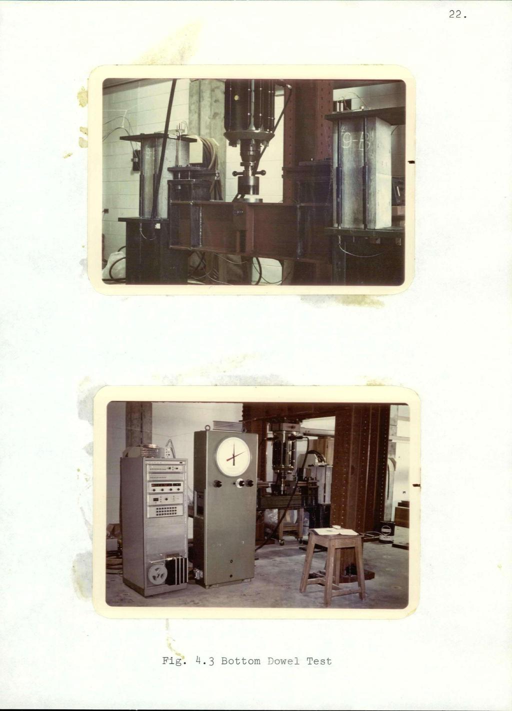
28 20. the steel dowels and the load applied at the mid-point of the beam. Fig. 4.2 and 4.3 show the positioning of the test specimens (two per test) and the method of load application. The load was applied with an Amsler hydraulic jack. The deflection of the steel dowel was measured at the column face (positions 1 and 2, Fig. 4.2).- Since the deflection probes from the transformers were positioned on the dowel itself, the steel clamps were attached 1/4" away from the column face to provide the necessary space for the probes. As a result of this set-up, some bending moment would be developed in the dowel at the column face. This is considered in the theoretical analysis; Linear transformers were again used to measure the deflections and both deflections and load were simultaneously recorded on punched paper tape on a Digital Data Acquisition unit. A computer program converted the paper tape data into the shear-deflection graphs which are presented in Appendix 1. Four curves were obtained for each dowel size. For simulating the actual column conditions, the concrete column specimens were compressively stressed to 1 Ksi with the tension rods (Fig. 4.2). The force in each tension rod was determined with a strainsert bolt. 4.2 ANALYSIS The behaviour of the bottom dowel embedded in the concrete column specimen was modelled as a beam-on-elastic foundation. Fig. 4.4b shows a semi-infinite beam on an elastic foundation as discussed in Timoshenko '. This model is assumed to represent the section shown in Fig. 4.4a.
29 STEEL CLAMP BRONZE SHIM TRANSFORMER PROBE FOR MEASURING 1/ DEFLECTION AT COLUMN FACE [ TEST SPECIMEN LOAD P TENSION ROD i z LOAOING BEAM STRAINS6KT BOLT T7777T / / / / / / / / / i i / / / / I /T7T Fig. 4.2 Loading Apparatus For Bottom Dowels
30
31 23. CONCRETE COLUMN SPECIMEN BOTTOM DOWEL RESIOM MODELLEP AS A BEAM-OH-ELASTIC FoUMPATIOM Fig. 4.4a Bottom Dowel Specimen BOTTOM OOWEL ELASTIC FOUNDATION" Fig. 4.4b Bottom Dowel Specimen as a Beam-on-elastic Foundation
32 The solution to the differential equation for a semiinfinite beam on an elastic foundation as shown in Pig. 4.4b is y(x) = e" ex (Pcosgx --pmc fcosgx-sinbx-] ) (4-1) where 3 = h,^ K E I = Foundation Modulus = modulus of elasticity of the beam = moment of inertia of the beam The values obtained for the foundation modulus in Chapter 3 were used in calculating the g term. Since the bottom dowel specimens had a concrete strength of 4,200 psi, the values for the foundation modulus were scaled by using a factor of ^H - = (Refer to page 17) The units of K are Ksi and the value for E in all the analysis was 29,000 Ksi (modulus of elasticity of the steel dowels). To determine the deflection at the column face, the value x = 0 must be substituted into equation 4-1. or rearranging y ; (x=0) = 2 ^ (P- P M o ) (4-2) P = 2g 3 EIy 4. 6 M (4-3) O As previously mentioned, since some room had to be provided forl-positioning the deflection probes onto the dowels, the steel clamps were not snug against the column face. Hence, the
33 bending moment that is developed in the dowel at the column face is opposite in sign to that shown in Fig; 4.4b. With the change in sign, equation 4-3 becomes P = 2g 3 EIy - g M Q. (4-4) When M Q is zero, equation 4-4 reduces to P = 2g 3 EIy (4-5) The two extreme values of "M are zero and M - the P plastic moment of the steel dowel. Equations 4-4 and 4-5 were superimposed on the shear-deflection curves of dowel sizes #4, #7 and #11, as shown in Pig. 4.5a, 4.5b and 4.5c. The experimental shear-deflection curve is an average of the 4 curves as shown in Appendix 1 for the corresponding dowel size. Table 4.1 lists the variables involved in this analysis. As can be noted from the graphs, the theoretical curves are below the experimental curve for the #11 dowel up to a deflection of 0.04". As the dowel size is reduced the two theoretical curves shift closer to the experimental curve until the upper line (equation 4-5) begins to exceed the experimental results at a deflection of 0.02" (#4 dowel size). Pig. 4.6 is a plot of the shear at 0.03" deflection for the range of bar sizes tested. Equations 4-4 and 4-5 are also plotted with the value of "y" equal to 0.03". The majority of the experimental points are bounded.by the two extreme equations. (Heavy dark vertical lines show the range in the experimental results.) Table 4.2 lists the values required in plotting Fig The 3 term was evaluated for a concrete strength of 4,200 psi.
34 Table 4.1 Bottom Dowel Variables Dowel Size Diameter d foment of Inertia (in.) ' I (in. 4 ) - Foundation Modulus K (Ksi) (for fi = 4200 psi) 3 = \f~p ( 1 ) / V4EI (in.) (E = Ksi) Plastic moment M = 0.l67f a 3 p. y (KIP-IN j # # # # # # # # #
35
36
37
38 Table 4.2 Shear at 0.03 Deflection f* = 4200 psi E = Ksi y = 0.03" Dowel Size Average Shear at 0.03" Deflection (Experiment) (KIPS) P = 2g 3 EIy - BM p (Kips) P = 2$ 3 EIy (Kips) # # # # # # # # #
39
40 32. The "knee" of the shear-deflection curves occurs (in most cases) at around the 0.0 3" value of deflection with the concrete still in the elastic range. At this deflection there were no visible signs of crushing or spalling' of the concrete around the dowel. Thus, for this reason the theoretical beam-on-elastic foundation equation was compared to the 0.03" value. Extrapolating the equation to higher values of deflection would result in overestimating the shear capacity, since the concrete under the dowel begins to crush and crack and the shear-deflection curves assume a shallower slope. Nevertheless, the experimental and theoretical values are in close agreement, at the 0.03" value for the entire range of dowel sizes, with some sizes experiencing more deviation than, others. Pig. 4.7 is a plot of equation 4-5 for varying values of concrete strengths. As was shown in Pig. 3.6, the foundation modulus K is not very sensitive to differences in concrete strength. Hence the 3 term is also rather insensitive to concrete strength, with the result that the two graphs (Pig. 4.7) do not have much variation. For a 50$ increase in concrete strength the maximum increase in shear capacity (for a #8 bar) is about 17%. The ultimate shear for each dowel was taken to be the stage at which the concrete was crushing under the dowel and no increase in load was possible. The ultimate shear and the shear at 0.03" deflection is plotted in Fig In most cases the ultimate shear is double that at 0.03" deflection. A design based on the 0.03" deflection curve would provide a safety factor of 2 in most cases.
41
42
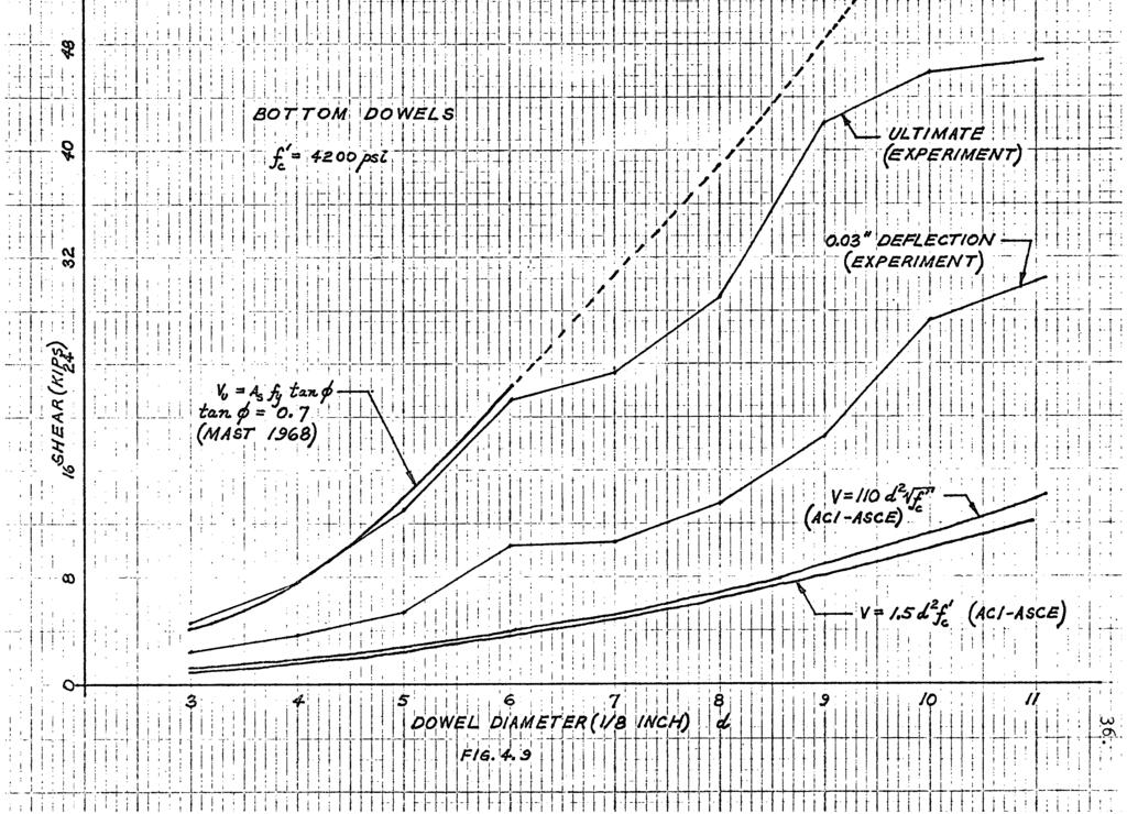
43 COMPARISON OF RESULTS WITH PREVIOUS WORK The results of these tests were compared to previous work which has been done with reinforcing steel dowels and metal studs. Fig. 4.9 presents the experimental results and two expressions from the ACI-ASCE Committee.There the allowable shear for reinforcing steel dowels is given by the expression V = A/(A f cose) 2 + (1.5d 2 f^ine) 2 * (4-6) <v s s c where d = sum of the diameter of bars or dowels 9 = angle between beam-column interface and the dowel. For 6= 90. (as is the case in this study), the expression reduces to V = 1.5d 2 f. <4-7) For a metal stud embedded in concrete, the allowable shear is given by where V = HOd 2 /^ (4-8) d = diameter of stud. ' Equations 4-7 and 4-8 are plotted and the relative positions of the graphs show that there is a considerable safety factor inherent in these expressions. (2) Also plotted is Mast's v expression. V u = A s f y tan<l>. (4-9) Although the method of testing the specimens did not have any shear-friction action, the expression was nevertheless compared to the experimental results by using the lowest value of
44

45 Pig Bottom Dowel Specimens at Ultimate Load
46 3.8. tancj) = 0.7 as suggested by Mast. There is excellent agreement between Mast's expression and the experimental results up to the #6 dowel. However, extrapolating the equation to the larger dowel sizes results in overestimating the ultimate shear as obtained in this experiment. Some of the larger dowel.sizes reached ultimate deflect tions of 0.5" to 0.7" (Appendix 1) while the smaller ones ranged between 0.2" to 0.4". An "average" ductility factor y for an individual dowel (based on the 0.03" deflection value as an elastic or yield limit) would be calculated as p ~ J-J.. Pig shows several specimens at ultimate load and the extent of damage to them. The test specimens had only two column ties (Pig. 4.1) and there was substantial diagonal cracking and spalling of the concrete at ultimate load (Fig and 4.11) for the larger dowel sizes. The smaller sizes experienced only local crushing and spalling under the dowel. DIAGONAL CRACKS STEEL DOWEL Fig Crack Pattern at Ultimate-Load
47 3.9. More column ties should be provided at such beam-column connections to prevent excessive cracking and spalling of the concrete. This hoop reinforcement would provide additional confinement to the concrete and as such increase the ultimate capacity of the dowel. A study of beam-column connections Was conducted by (4) Hanson and Connor x. They found that confinement of the concrete at critical sections such as beam-column connections increases the ductility of the joint. The hoop reinforcement resists the tendency of the joint to expand under multiple reversals of beam loading. For joints that are confined on at least three sides by beams or spandrels, hoop reinforcement in the joint region is not required. For uhcdnfined or isolated beam-column joints, hoop reinforcement is most beneficial.
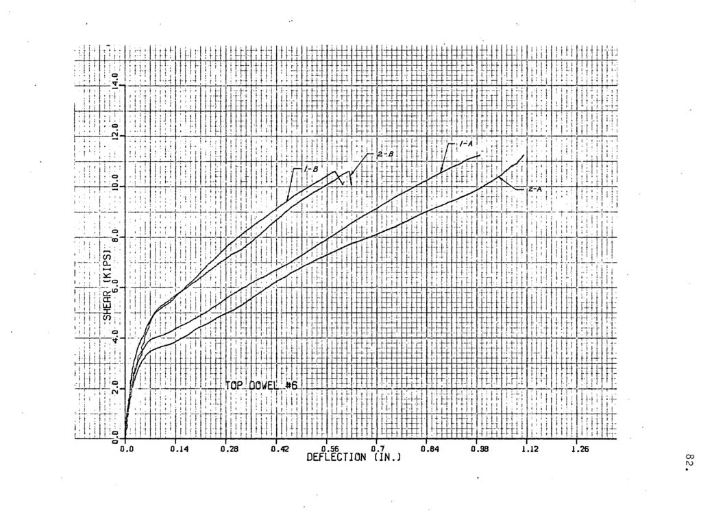
48 40. CHAPTER 5 TOP DOWEL TESTS 5.1 LABORATORY TEST PROGRAM To determine the shear capacity of the top dowels in a beam-column joint, 16 beam specimens were tested. Pig. 5-1 shows a typical beam specimen. Again the variable was dowel diameter. Two such specimens were cast for each bar size - #4 to #11 inclusive. Forming, pouring and curing of the test specimens were done by the standard procedure as outlined in Chapter 2. The distance from the beam end to the first stirrup was kept constant at 1 inch. A previous study by Petershowed that the shear capacity was significantly influenced by the distance to the first stirrup.. He varied the distance from 1 inch to 3 inches and obtained the maximum shear with the 1 inch position. His tests were done for a #5 top dowel only. To determine if the beam stirrup spacing has any effect on the shear capacity of the top dowel, one-half of the beam had the stirrup spacing as required by the ACI code (318-71) and the other half had double the specified spacing. The testing apparatus is shown in Fig. 5.2 and Fig Not.shown in Fig. 5.2 are two end roller restraints placed against the sides of the test beam and clamped to the end supports. (These are visible in the photographs, Fig. 5.3.) The rollers prevented the beam from rotating laterally as the load was applied. Deflections were measured with linear transformers at
49 TOP DOWEL STIRRUPS d (REFER To TABLE Fig. 5.1 Top Dowel Specimen
50 Table 5.1 Top Dowe 1 Test Specimens Top Dowel Size S (In.) h (in.) Stirrup Size # #3 #5 12 #3 #6 5 *\ 12 #3 #7 12 #3 #8 16 #3 #9 6, 16 #4 #10 3k 16 #4 #11 3k 16 #4
51 SEC. A-A TOP DOWEL LOAD TEST BEAM 771 DEFLECTION (f) DEFLECTION 0 Pig. 5.2 Top Dowel Test Apparatus

52 Fig. 5-3 Top Dowel Test 44.
53 positions 1 and 2 (Fig. 5-2) and both load and deflections were recorded on punched paper tape. As before, a computer program converted the punched paper tape data into the shear-deflection graphs which are presented in Appendix ANALYSIS As in the bottom dowel analysis, a model was chosen for the top dowel behaviour. Fig. 5.4 shows the end region of the test beam with a shear force V applied to the dowel at the beam end. In order to analyze this' end region as a unit, the section is transformed as shown in Fig If the section shown in Fig. 5-5 is assumed to act as a 1" long cantilever beam, the moment that is developed before the section ruptures in tension Is f r J t M = - f i (5-1) ^b where the modulus of rupture of concrete f r. = 7.5AJfJ\ 1^ = moment of inertia of transformed section and = distance from the neutral axis of the transformed section to the extreme fiber in tension. With the concentrated load V at the end of the cantilever M = V*l" or V*l" = f r T t. ( 5-2 ) Table 5.2a lists a l l the variables required to plot equation 5-2. Fig. 5.6a shows the experimental results and a
54 Fig. 5.4 Shear V acting on Top Dowel h = AREA OF Top DOWEL MODULAR RATIO >i=ja. a o Fig. 5.5 Transformed Section
55 Table 5.2a Transformed Section Properties 7-5^T h Top Dowel Size f r (in. 4 ) i (Ksi)! Y b (in.) V = Y b (Kips) # # # # # # # #
56
57 Table 5.2b Normalized Experimental Results Dowel Size V = KIPS) b : f 1 c Ksi V c Vexp. Shear at 0.03" Defln. (KIPS) Vexp. f 1 c # # # O.96 # # , # # #
58
59 plot of equation 5-2. Due to varying concrete strengths and hence varying f, the graph of equation 5-2 is not a : smooth and constantly increasing curve. In Fig. 5.6b, equation 5-2 and the data points have been normalized. Each value of Fig. 5.6a has been divided by the corresponding concrete strength f* for that particular case (Table 5.2b). Both analytical and experimental curves exhibit similar shapes. This model is reasonably accurate up to the #8 dowel size and begins to deviate substantially for the larger dowels. The cantilever model requires that the end condition be fixed, i.e., a fixed condition at the first stirrup location. This condition holds for the smaller dowels where the first stirrup does not yield and bending occurs in the top dowel within the 1" cantilever distance. On the other hand, the large dowels simply will not bend in a 1" distance and hence tend to yield the first stirrup in direct tension. Thus the fixed condition at the first stirrup would not hold true. The above model does not take into account any direct tensile stresses or the effect of yielding of the first stirrup. These two points will be considered now. The first visible sign of any cracking in the top dowel tests was as shown in Fig. 5-7> where a longitudinal crack propagated from the top dowel out towards the beam sides and then horizontally along the beam. The area over which direct tension occurs is a rectangle 6" (beam width) by 1" (distance to first stirrup), i.e., 6 square inches. With the tensile strength of
60 Pig. 5.7 Crack Propagation in Top Dowel Test 52.
61 .5.3. concrete taken as 7.5A^^J the shear force required to crack the section can be calculated -directly as V =.7.5AFT *6 (5-3) The results of this calculation are listed in Table 5.3 and Fig. 5-9 shows a plot of equation 5-3 in relation to other experimental values. The effect of the first stirrup yielding shall be considered next. Fig. 5.8 illustrates the condition at the first stirrup where the shear force V is resisted by the tension in the stirrup. The values given in Table 5.4 are plotted in Fig. 5.9,as two discontinuous straight lines (stirrup sizes #3 and #4). These two lines agree reasonably well with the ultimate values obtained from experiment. In this test series, it was difficult to compare the experimental and model deflections. Since the first stirrup will strain and therefore extend under the application of load, the deflection that is measured at positions 1 (or 2.) is not identically the same as the deflection of the top dowel vertically above position 1 (or 2). (Refer to Fig. 5.2.) As shown in Fig: 5.9, the ultimate shear is considerably higher than that obtained at 0.03" deflection.. The #4 dowel failed in shear at ultimate (Fig. 5.10). In the case of #7 and #8 dowels, the first stirrup ruptured at ultimate. (Fig. 5.11). The #9, #10 and #11 test specimens had #4 size stirrups and in these three cases the concrete beam failed in shear (at the end with the larger stirrup spacing - Fig. 5.13),
62 Table 5-3 Direct Tensile Force Dowel Size f r = 7 ' 5 / fc' ( K s l ) V = 7.5A^*6 (KIPS) # # # # #11 O.58O 3.48
63 Fig. 5.8 Yielding of the First Stirrup Table 5.4 Tension at Stirrup Yield Dowel Size Stirrup Size A s Stirrup 2 Area (in.) f (Ksi) 2T = A s KIPS f J #4 #5 #6 # #7 #8 #9 #10 # #11
64 <b! : ;.7. ; I : j -; M 0OW L\ P/AM TER(J/a /NCH) /7G. SIS : I I 'j 1 I! I 1. I
65 57.
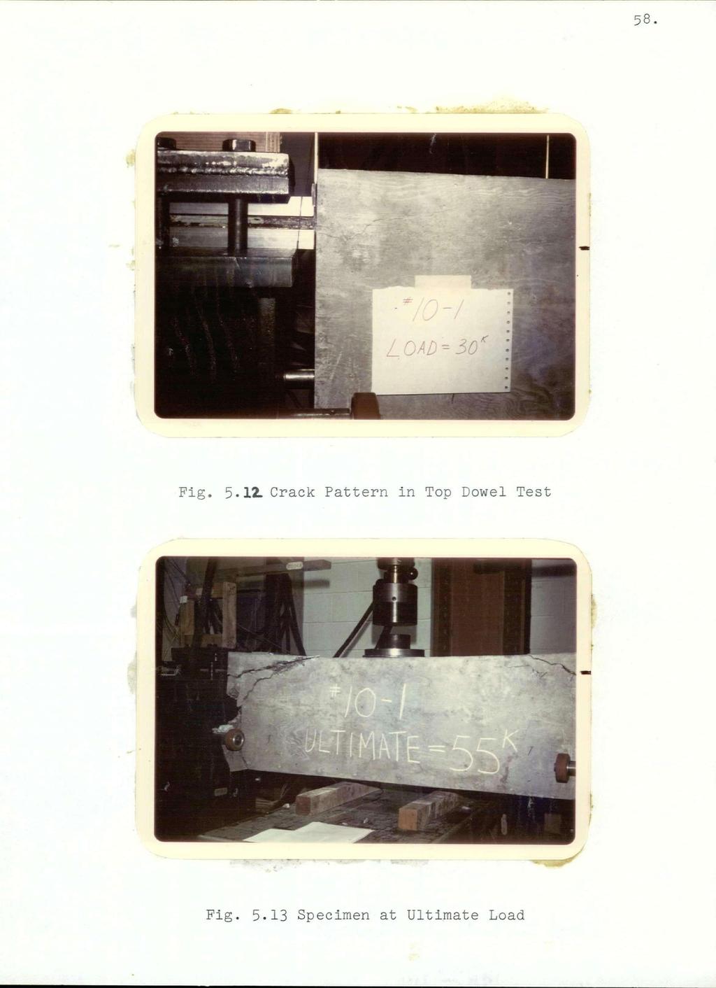
66 58.
67 59. Even though the stirrup spacing was varied on both halves of the test beams, no significant differences in the behaviour or cracking patterns was observed between the two ends. Pigs and 5.13 show the crack patterns during testing and at ultimate load.
68 6.0. CHAPTER 6. THE JOINT:SUM OF TOP AND BOTTOM DOWELS The previous two chapters have discussed bottom and top dowel tests and analysis. In this chapter the results are combined and the shear capacity of a beam-column joint is calculated. The graphs in Fig. 6.1 are the theoretical values obtained previously, plotted for the same deflection (0.03 in.) for both bottom and top dowels. As can be noted from the graphs, the bottom dowels contribute most to the shear capacity of a joint. In nearly all cases, the shear for a top dowel is between 33-44% of that for the same size bottom dowel. For the bottom dowel curve, the value for the foundation modulus K (and hence g) corresponds,!; to a Concrete strength of f* equal to 4,000 psi. Similarly, the modulus of rupture f is calculated for the same concrete strength and equation 5-2 plotted. The joint shown in Fig. 6.2 could be considered as a design problem. All the shear is to be transferred by dowel action and hence the shear capacity of this joint can be calculated by using the graphs presented in Fig In determining the shear capacity of the bottom dowels in this case, the expression P = 2g 3 EIy is used. The bending moment term gm is neglected in this case because it is extremely doubtful that the plastic bending moment could be developed in the bottom dowels at the beam-column interface. The deflection of the bottom dowels is symmetric about the beam-column interface with the point of inflection occurring at the beam-column interface.
69 t I!!! BOTTOM, AND TOP ; POWELS 6.! i! '.7,..; j! : ; 8 : DOWEL D/AMEfERfl/B /#CH) /0
70 Pig. 6.2 Design Beam-Column Joint 6.2.
71 \ 63. From the graphs of Fig. 6.1: Bottom Dowel shear: 2 x k Top Dowel shear: 2 x k Total 40.8* The shear capacity of this joint, assuming dowel action only, is 40 kips (service load shear). As shown in Fig. 6.2, the first stirrup should be placed around each top dowel individually. This provides the necessary tie-down force to the top dowels and hence a greater contribution to the shear capacity. As was mentioned before, the shear capacity of the top dowels is sensitive to the distance to the first stirrup. Also, since the deflection of the bottom dowels is assumed to be symmetrical about the beam-column interface, the net beam deflection would be " at a shear force of 40 kips. At such small deflections, the stress pattern around one dowel is assumed not to influence the behaviour of its neighbouring dowel. Hence the shear capacity of the dowels is assumed to be additive directly. At large deflections, the interaction and overlapping of stress patterns between neighbouring dowels may be significant..therefore the ultimate shear capacities would not be additive directly. This analysis has neglected the effect of friction and bending moment at the beam-column interface. These effects, however, will only help to increase the shear capacity of the joint and therefore a design based only on the dowel action of the reinforcing bars provides a lower bound on the joint capacity.
72 Fig. 6.3 shows the relative positions of the graphs for ultimate shear for!both top and bottom dowels. These graphs, however, can riot be used to accurately predict the ultimate shear capacity for a combination'-.of top and bottom dowels because of interactive stress effects between dowels.
73
74 6.6. CHAPTER 7. CONCLUSIONS 1. The beam-on-elastic foundation analogy forms a reasonable method of modelling the behaviour of the bottom dowel and its applicability could be confidently extrapolated to other situations which are not exactly the same as those presented here. 2. The beam-on-elastic foundation model should not be extrapolated to large values of deflection; 0.03" deflection is a recommended upper limit. 3. A beam column joint designed solely on the basis of dowel action of the reinforcing steel.bars may provide adequate shear capacity. 4. The bottom dowels are the major shear-carrying components of a beam-column joint. * 5. The top dowel should be well anchored by the first stirrup if it is to contribute to the shear capacity of the joint. 6. The variation of stirrup spacing in the beam specimens did not have any effect on the shear capacity of the top dowels. 7. There is a wide range of values for the foundation modulus between the small and large dowels to 1,000 Ksi.
75 67. REFERENCES 1. Peter, B.G.W., M.A.Sc. Thesis, University of British Columbia, Vancouver, Mast, R. F., "Auxiliary Reinforcement in Concrete Connections", J. Str. Div. ASCE, June 1968, pp Hofbeck, J. A., Ibrahim, I.O., and Mattock, Alan H., "Shear Transfer in Reinforced Concrete", ACI Journal, February 1969, pp Hanson, Norman W. and Connor, Harold W., "Seismic Resistance of Reinforced Concrete Beam-Column Joints", J. Str. Div. ASCE, October 1967, pp Timoshenko, S., "Strength of Materials - Part II", Princeton, N.J., D. Van Nostrand Company Inc., March Birkeland, Philip W. and Birkeland, Halvard W., "Connections in Precast Concrete Construction", ACI Journal, March 1966, PP Kriz, L. B. and Raths, C. H., "Connections in Precast Concrete Structures - Strength of Corbels", PCI Journal, February 1965, pp. l6-6l. 8. Gaston, J. R. and Kriz, L. B., "Connections in Precast Concrete Structures - Scarf Joints", PCI Journal, June 1964, PP ACI-ASCE Committee 512, "Suggested Design of Joints and Connections In Precast Structural Concrete", ACI Journal,
76 August 1964, pp : Prestressed Concrete Institute, "PCI Design Handbook Precast and Prestressed Concrete", Chicago, Illinois, Kratz, R. D., M.A.Sc. Thesis, University of British Columbia, Vancouver, Dulacska, Helen, "Dowel Action of Reinforcement Crossing Cracks in Concrete", ACI Journal, December 1972, pp Anderson, Arthur R., "Composite Designs in Precast and Castin-Place Concrete", Progressive Architecture, September I960, pp
77 69. APPENDIX 1. BOTTOM DOWEL EXPERIMENTAL GRAPHS The following graphs are the experimental shear-deflection results for the bottom dowel tests. Each graph is labelled according to the notation used in Fig. 4.2 in Chapter 4. For example, a curve labelled as 1-A indicates the deflection at position 1 of test series A.
78
79
80
81
82
83
84
85
86
87 79. APPENDIX 2. TOP 'DOWEL. EXPERIMENTAL GRAPHS The following graphs are the experimental shear-deflection results for the top dowel tests. Each graph is labelled according to the notation used in Pig. '5.2 in Chapter 5. For example, a curve labelled as 1-A indicates the deflection at position 1 of test series A.
88 *08
89 18
90
91 SHEAR (KIPS) J L _L
92
93
94 *98
95
Design of structural connections for precast concrete buildings
 BE2008 Encontro Nacional Betão Estrutural 2008 Guimarães 5, 6, 7 de Novembro de 2008 Design of structural connections for precast concrete buildings Björn Engström 1 ABSTRACT A proper design of structural
Dowel connections in laminated strand lumber
 Dowel connections in laminated strand lumber Cranswick, Chad J. 1, M c Gregor, Stuart I. 2 ABSTRACT Laminated strand lumber (LSL) is a relatively new structural composite lumber. As such, very limited
Anti-check bolts as means of repair for damaged split ring connections
 Anti-check bolts as means of repair for damaged split ring connections Quenneville, J.H.P. 1 and Mohammad, M. 2 ABSTRACT There are numerous large span timber hangars dating back to the Second World War.
Dowels for the 21st Century
 Dowels for the 21st Century by Wayne W. Walker and Jerry A. Holland sing plate dowels in slabs on ground for shear load transfer at the joints offer many advantages over the traditional round dowels. By
Moment-Resisting Connections In Laminated Veneer Lumber (LVL) Frames
 Frames") Moment-Resisting Connections In Laminated Veneer Lumber (LVL) Frames Andy van Houtte Product Engineer-LVL Nelson Pine Industries Nelson, NZ Andy Buchanan Professor of Civil Engineering Peter Moss Associate
Moment-Resisting Connections In Laminated Veneer Lumber (LVL) Frames Andy van Houtte Product Engineer-LVL Nelson Pine Industries Nelson, NZ Andy Buchanan Professor of Civil Engineering Peter Moss Associate
American Institute of Timber Construction 7012 South Revere Parkway Suite 140 Centennial, CO Phone: 303/ Fax: 303/
 American Institute of Timber Construction 7012 South Revere Parkway Suite 140 Centennial, CO 80112 Phone: 303/792-9559 Fax: 303/792-0669 404.1. SCOPE STANDARD FOR RADIALLY REINFORCING CURVED GLUED LAMINATED
Connection Philosophy. p NDS Chapter-by-chapter description Changes from previous editions Examples. Part 1: Member Design Webinar.
 Outline ASD and LRFD with the 2005 NDS Part 2 Connection Design Presented by: John Buddy Showalter, P.E. Vice President, Technology Transfer Connection philosophy p NDS Chapter-by-chapter description Changes
STRUCTURAL TIMBER DESIGN
 STRUCTURAL TIMBER DESIGN to Eurocode 5 2nd Edition Jack Porteous BSc, MSc, DIC, PhD, CEng, MIStructE, FICE Director lack Porteous Consultancy and Abdy Kernlani BSc, MSc, PhD, CEng, FIStructE, FIWSc Professor
The Behaviour Of Round Timber Sections Notched Over The Support On The Tension Face. Justin Dewey
 The Behaviour Of Round Timber Sections Notched Over The Support On The Tension Face Justin Dewey Need for research In Queensland there are approximately 400 timber bridges still in use. Very little research
Lawrence A. Soltis, M. and Robert J. Ross, M. 1
 REPAIR OF WHITE OAK GLUED-LAMINATED BEAMS Lawrence A. Soltis, M. and Robert J. Ross, M. 1 Abstract Connections between steel side plates and white oak glued-laminated beams subjected to tension perpendicular-to-grain
Bolts and Set Screws Are they interchangeable?
 1903191HA Bolts and Set Screws Are they interchangeable? Prof. Saman Fernando Centre for Sustainable Infrastructure SUT Introduction: This technical note discusses the definitions, standards and variations
Connection and Tension Member Design
 Connection and Tension Member Design Notation: A = area (net = with holes, bearing = in contact, etc...) Ae = effective net area found from the product of the net area An by the shear lag factor U Ab =
Glulam Connection Details
 T E C H N I C A L N O T E Glulam Connection Details Note: This version is superseded by a more current edition. Check the current edition for updated design and application recommendations. ENGINEERED
Module 10 : Improvement of rock mass responses. Content
 IMPROVEMENT OF ROCK MASS RESPONSES Content 10.1 INTRODUCTION 10.2 ROCK REINFORCEMENT Rock bolts, dowels and anchors 10.3 ROCK BOLTING MECHANICS Suspension theory Beam building theory Keying theory 10.4
Wall Form Design Part I
 Wall Form Design Part I Lecture 3 Bearing or rushing Bearing Stresses (ompression Perpendicular to the Grain) Allowable stresses for compression perpendicular to the grain are available from tables providing
PRECAST CONCRETE STRUCTURES
 PRECAST CONCRETE STRUCTURES 1. INTRODUCTION The concept of precast (also known as prefabricated ) construction includes those buildings, where the majority of structural components are standardized and
Section 914. JOINT AND WATERPROOFING MATERIALS
 914.01 Section 914. JOINT AND WATERPROOFING MATERIALS 914.01. General Requirements. Joint and waterproofing material for use in concrete construction must meet the requirements of this section. 914.02.
Double Shear Testing of Bolts
 University of Wollongong Research Online Coal Operators' Conference Faculty of Engineering and Information Sciences 23 Double Shear Testing of Bolts N. Aziz University of Wollongong, naj@uow.edu.au D.
Dowel. Design. Performance-Based World of Concrete Official Show Issue. Lift-truck design changes require a new look at joint durability
 2007 World of Concrete Official Show Issue January 2007 Performance-Based Dowel Lift-truck design changes require a new look at joint durability Design By Wayne W. Walker and Jerry A. Holland S erviceability
A. Extent of structural precast concrete work is shown on drawings and in schedules.
 SECTION 03 41 00 - STRUCTURAL PRECAST CONCRETE PART 1 GENERAL 1.1 RELATED DOCUMENTS A. Drawings and general provisions of Contract, including General and Supplementary Conditions and Division 1 specification
Innovative composite dowel for steel concrete composite bridges. Neil Westmacott, Wolfram Schwarz
 Innovative composite dowel for steel concrete composite bridges Neil Westmacott, Wolfram Schwarz At a glance Cost effective alternative to prestressed bridge girders Introduction New to Australia although
SECTION METAL FABRICATIONS
 SECTION 05100 PART 1 - GENERAL 1.01 DESCRIPTION A. Section includes specifications for metal fabrications, including minimum requirements for fabricator, and galvanizing. 1.02 REFERENCE STANDARDS A. ASTM
Initiating Cracks in PCC Pavements. Malcolm K. Lim, PE
 Initiating Cracks in PCC Pavements by Malcolm K. Lim, PE Technology Transfer Concrete Consortium (TTCC) and National Concrete Consortium (NCC) Fall 2009, St Louis, MO Better Performance Through Innovative
Effect of shoulders on bending moment capacity of round mortise and tenon joints
 Effect of s on bending moment capacity of round mortise and tenon joints Carl Eckelman Yusuf Erdil Eva Haviarova Abstract Tests were conducted to determine the effect of close-fitting s on the bending
Flanged Dowel Box. Load Transfer System INDUSTRIAL SLAB ON GROUND
 Flanged Dowel Box INDUSTRIAL SLAB ON GROUND Designed for construction joints in Post Tension or large shrinkage specifications Large lateral movement and expansion capacity Eliminates the need to drill
RlGIDITY AND STRENGTH OF WALL FRAMES BRACED WlTH METAL STRAPPING
 RlGIDITY AND STRENGTH OF WALL FRAMES BRACED WlTH METAL STRAPPING information Reviewed and Reaffirmed March 1955 No. R1603 UNITED STATES DEPARTMENT OF AGRICULTURE FOREST SERVICE FOREST PRODUCTS LABORATORY
Skewed connections result when members frame to each
 Design of Skewed Connections LARRY KLOIBER and WILLIAM THORNTON ABSTRACT Skewed connections result when members frame to each other at an angle other than 90º. This paper provides some guidance in the
Experimental Study on Pile Groups Settlement and Efficiency in Cohesionless Soil
 Experimental Study on Pile Groups Settlement and Efficiency in Cohesionless Soil Elsamny, M.K. 1, Ibrahim, M.A. 2, Gad S.A. 3 and Abd-Mageed, M.F. 4 1, 2, 3 & 4- Civil Engineering Department Faculty of
A Solution to Cracking and Stresses Caused by Dowels and Tie Bars
 Square bars and a special clip-on plastic sheath solve the problem A Solution to Cracking and Stresses Caused by Dowels and Tie Bars by Ernest K. Schrader D owels and tie-bars are important to the design
WOODEN BUILDINGS 6.1 INTRODUCTION 6.2 TYPICAL DAMAGE AND FAILURE OF WOODEN BUILDINGS. Chapter 6
 Chapter 6 WOODEN BUILDINGS 6.1 INTRODUCTION Wood has higher strength per unit weight and is, therefore, very suitable for earthquake resistant construction. But heavy cladding walls could impose high lateral
nineteen Wood Construction 1 and design APPLIED ARCHITECTURAL STRUCTURES: DR. ANNE NICHOLS FALL 2016 lecture STRUCTURAL ANALYSIS AND SYSTEMS ARCH 631
 APPLIED ARCHITECTURAL STRUCTURES: STRUCTURAL ANALYSIS AND SYSTEMS DR. ANNE NICHOLS FALL 2016 lecture nineteen wood construction and design Wood Construction 1 Timber Construction all-wood framing systems
Cyclic Response of Dowel Connections in Precast Structures
 Cyclic Response of Dowel Connections in Precast Structures M. Fischinger, B. Zoubek, M. Kramar, T. Isaković University of Ljubljana, Faculty of Civil and Geodetic Engineering, Slovenia SUMMARY: Precast
State-of-the-art Report On FULL-DEPTH PRECAST CONCRETE BRIDGE DECK PANELS (SOA )
") State-of-the-art Report On FULL-DEPTH PRECAST CONCRETE BRIDGE DECK PANELS (SOA -01-1911) Vince Campbell Former president of Bayshore Concrete Products Corporation, VA This presentation is developed
State-of-the-art Report On FULL-DEPTH PRECAST CONCRETE BRIDGE DECK PANELS (SOA -01-1911) Vince Campbell Former president of Bayshore Concrete Products Corporation, VA This presentation is developed
MAT105: Floor Framing
 MAT105: Copyright 2007 American Forest & Paper Association, Inc. Because the common applications for wood framing are in residential construction, the details of this program will be based on the IRC which
Suggested Reinforcement Detailing Practices Based on comments from R&D and ES ESS Committees
 Suggested Reinforcement Detailing Practices Based on comments from R&D and ES ESS Committees General 1. When detailing substructures, it is preferable not to use series bars unless necessary. The first
TECHNICAL MANUAL. TERADOWEL and ULTRADOWEL. Reliable Dowel System for Floor Joints
 TECHNICAL MANUAL TERADOWEL and ULTRADOWEL Reliable Dowel System for Floor Joints Version: PEIKKO GROUP 11/2018 TERADOWEL and ULTRADOWEL Reliable Dowel System for Floor Joints Dowels manufactured from high
DOWEL ACTION OF TITANIUM BARS CONNECTING MARBLE FRAGMENTS AT DIFFERENT ANGLES
 13 th International Brick and Block Masonry Conference Amsterdam, July 4-7, 2004 DOWEL ACTION OF TITANIUM BARS CONNECTING MARBLE FRAGMENTS AT DIFFERENT ANGLES E.Vintzileou 1, E.-E.Toumbakari 2 Abstract
Index Terms: Lathe waste concrete; Shear and bending; Shear strength; Stirrups; Simply supported beams.
 TASC- 15, 1-11 June 15 Effect of Lathe Waste in Concrete as Reinforcement Prof. Kumaran M 1,Nithi M. 2, Reshma, K. R. 3 Civil Engineering 1, Professor1, Universal Engineering College, Thrissur, Kerala,
Structural Strength of Lapped Cold-Formed Steel Z-Shaped Purlin Connections with Vertical Slotted Holes
 Missouri University of Science and Technology Scholars' Mine International Specialty Conference on Cold- Formed Steel Structures (2014) - 22nd International Specialty Conference on Cold-Formed Steel Structures
1. Enumerate the most commonly used engineering materials and state some important properties and their engineering applications.
 Code No: R05310305 Set No. 1 III B.Tech I Semester Regular Examinations, November 2008 DESIGN OF MACHINE MEMBERS-I ( Common to Mechanical Engineering and Production Engineering) Time: 3 hours Max Marks:
3.1 General Provisions
 WOOD FRAME CONSTRUCTION MANUAL 107 3.1 General Provisions 3.1.1 Prescriptive Requirements The provisions of this Chapter establish a specific set of resistance requirements for buildings meeting the scope
4.0 MECHANICAL TESTS. 4.2 Structural tests of cedar shingles
 4.0 MECHANICAL TESTS 4.1 Basis for the test methodology The essence of deterioration is that while it may be caused by insects, weather, fungi or bacteria, the decay is not identical. Further, no two physical
Composite Sections. Introduction BETON PRATEGANG TKS Session 10: 2015/4/27
 BETON PRATEGANG TKS - 4023 Session 10: Composite Sections Dr.Eng. Achfas Zacoeb, ST., MT. Jurusan Teknik Sipil Fakultas Teknik Universitas Brawijaya Introduction A composite section in context of prestressed
AMTS STANDARD WORKSHOP PRACTICE. Bond Design
 AMTS STANDARD WORKSHOP PRACTICE Reference Number: AMTS_SWP_0027_2008 Date: December 2008 Version: A 1 Contents 1 Technical Terms...3 2 Scope...3 3 Primary References...3 4 Basic...3 4.1 Typical joint types...4
PD 3 Dowel Cradle. Load Transfer System Industrial Slab on Ground
 PD 3 Dowel Cradle Industrial Slab on Ground Provides the flattest joints Assists in reducing long term maintenance costs Extends the life-cycle of the floor and the asset Engineered to meet Super Flat
Total precast solution for large stadium projects meet tight schedule
 Tailor Made Concrete Structures Walraven & Stoelhorst (eds) 2008 Taylor & Francis Group, London, ISBN 978-0-415-47535-8 Total precast solution for large stadium projects meet tight schedule T.J. D Arcy
Cast-in Ferrule Connections Load/Displacement Characteristics in Shear
 Cast-in Ferrule Connections Load/Displacement Characteristics in Shear Ian Ferrier 1 and Andrew Barraclough 2 1 Product Manager - Connections, ITW Construction Systems ANZ. 2 Research and Development Manager,
Korean standards of visual grading and establishing allowable properties of softwood structural lumber
 Korean standards of visual grading and establishing allowable properties of softwood structural lumber Park, Moon-Jae 1, Shim, Kug-Bo 1 ABSTRACT Korean standards related to wood products such as "Sizes
1/2/2016. Lecture Slides. Screws, Fasteners, and the Design of Nonpermanent Joints. Reasons for Non-permanent Fasteners
 Lecture Slides Screws, Fasteners, and the Design of Nonpermanent Joints Reasons for Non-permanent Fasteners Field assembly Disassembly Maintenance Adjustment 1 Introduction There are two distinct uses
ESR-1254 * DELETED BY CITY OF LOS ANGELES. Reissued April 1, 2006 This report is subject to re-examination in one year.
 ESR-1254 Reissued April 1, 2006 This report is subject to re-examination in one year. www.icc-es.org Business/Regional Office 5360 Workman Mill Road, Whittier, California 90601 (562) 699-0543 Regional
MODELLING OF CONCRETE PAVEMENT DOWEL-SLAB INTERACTION
 4 e Conférence spécialisée en génie des transports de la Société canadienne de génie civil 4 th Transportation Specialty Conference of the Canadian Society for Civil Engineering Montréal, Québec, Canada
REINFORCEMENT DESIGN FOR METAL BUILDING SYSTEMS
 REINFORCEMENT DESIGN FOR METAL BUILDING SYSTEMS By Donald L. Johnson, P.E. RETROFIT PROJECTS CAN BE NECESSARY FOR ANY NUMBER OF REASONS, though change in use is one of the most common. Change of use can
Tension Perpendicular to Grain Strength of Wood, Laminated Veneer Lumber, and a Wood Plastic Composite.
 Tension Perpendicular to Grain Strength of Wood, Laminated Veneer Lumber, and a Wood Plastic Composite. Tracy Hummer, Research Assistant J. Daniel Dolan, Professor Michael Wolcott, Professor Wood Materials
A Tale of Tearouts: Web Supplement
 A Tale of Tearouts: Web Supplement This is a supplement to the May 2017 Modern Steel Construction article A Tale of Tearouts (available at www.modernsteel.com/archives). The information presented here
Module 3 Selection of Manufacturing Processes
 Module 3 Selection of Manufacturing Processes Lecture 4 Design for Sheet Metal Forming Processes Instructional objectives By the end of this lecture, the student will learn the principles of several sheet
Unit IV Drawing of rods, wires and tubes
 Introduction Unit IV Drawing of rods, wires and tubes Drawing is a process in which the material is pulled through a die by means of a tensile force. Usually the constant cross section is circular (bar,
ESR-1799 Reissued April 2014 This report is subject to renewal June 1, 2015.
 ICC-ES Evaluation Report www.icc-es.org (800) 42-6587 (562) 699-054 ESR-799 Reissued April 204 This report is subject to renewal June, 205. A Subsidiary of the International Code Council DIVISION: 0 00
Hydraulic Tensioner Assembly: Load Loss Factors and Target Stress Limits
 Proceedings of the ASME 214 Pressure Vessels & Piping Conference PVP214 July 2-24, 214, Anaheim, California, USA PVP214-28685 Hydraulic Tensioner Assembly: Load Loss Factors and Target Stress Limits Warren
COLUMN 11/2013 LINEAR STRUCTURAL ELEMENT
 11/2013 LINEAR STRUCTURAL ELEMENT OÜ TMB Element produces linear structural elements with the product name column in conformity with the standard EVS-EN 13225 Precast concrete products. Linear structural
Title. CitationJournal of Wood Science, 58(4): Issue Date Doc URL. Rights. Type. File Information.
: Issue Date Doc URL. Rights. Type. File Information.") Title Effective lateral resistance of timber-plywood-timbe Author(s)Wanyama, Okumu Gordon; Sawata, Kei; Hirai, Takuro; K CitationJournal of Wood Science, 58(4): 315-321 Issue Date 2012-08 Doc URL http://hdl.handle.net/2115/50078
Title Effective lateral resistance of timber-plywood-timbe Author(s)Wanyama, Okumu Gordon; Sawata, Kei; Hirai, Takuro; K CitationJournal of Wood Science, 58(4): 315-321 Issue Date 2012-08 Doc URL http://hdl.handle.net/2115/50078
PERFORMANCE OF COMPOSITE SHEAR WALL PANEL OF LVL AND GRC BOARD
 PERFORMANCE OF COMPOSITE SHEAR WALL PANEL OF LVL AND GRC BOARD Maryoko Hadi 1, Rudi Setiadji 2, Anita Firmanti 3, Bambang Subiyanto 4, Kohei Komatsu 5 ABSTRACT: The low-cost housing for the people is the
SECTION CONCRETE REINFORCEMENT FOR STEAM UTILITY DISTRIBUTION
 PAGE 032015-1 SECTION 032015 PART 1 - GENERAL 1.1 RELATED DOCUMENTS A. Drawings and general provisions of the Contract, including General and Supplementary Conditions and Division 01 Specification sections,
Fasteners. Fastener. Chapter 18
 Fasteners Chapter 18 Material taken from Mott, 2003, Machine Elements in Mechanical Design Fastener A fastener is any device used to connect or join two or more components. The most common are threaded
a) If a bolt is over-tightened, which will fail first the bolt, or the plastic?
 If a bolt is over-tightened, which will fail first the bolt, or the plastic?") 2.2.75 6.525 Problem Set 3: Solutions to ME problems Fall 2013 Jacob Bayless Problem 1: Bolted joint a) If a bolt is over-tightened, which will fail first the bolt, or the plastic? The bolt is made of
2.2.75 6.525 Problem Set 3: Solutions to ME problems Fall 2013 Jacob Bayless Problem 1: Bolted joint a) If a bolt is over-tightened, which will fail first the bolt, or the plastic? The bolt is made of
Copyright. Michael Joseph Gilroy. May 1997
 Copyright by Michael Joseph Gilroy May 1997 Tightening of High Strength Metric Bolts by Michael Joseph Gilroy, B.S. Thesis Presented to the Faculty of the Graduate School of The University of Texas at
ANALYSIS OF LATERAL STIFFNESS FOR INFILLED FRAME WITH OPENING
 ANALYSIS OF LATERAL STIFFNESS FOR INFILLED FRAME WITH OPENING A.S. KASNALE 1 & SANJAY JAMKAR 2 Professor in Civil Engineering Department, M.S. Bidve Engineering College, Latur, India Professor in Civil
A training course delivered at a company s facility by Matrix Engineering, an approved provider of Bolt Science Training
 A training course delivered at a company s facility by Matrix Engineering, an approved provider of Bolt Science Training Following is an outline of the material covered in the training course. Each person
TECHNICAL MANUAL. OPTIMAJOINT Free Movement Joint. Free Movement Joint System for Heavy Traffic
 TECHNICAL MANUAL OPTIMAJOINT Free Movement Joint Free Movement Joint System for Heavy Traffic Version: PEIKKO GROUP 12/2018 OPTIMAJOINT Free Movement Joint Free Movement Joint System for heavy traffic
CH # 8. Two rectangular metal pieces, the aim is to join them
 CH # 8 Screws, Fasteners, and the Design of Non-permanent Joints Department of Mechanical Engineering King Saud University Two rectangular metal pieces, the aim is to join them How this can be done? Function
Space-frame connection for small-diameter round timber
 Space-frame connection for small-diameter round timber Wolfe, Ronald W., 1 Gjinolli, Agron E., 1 and King, John R. 2 ABSTRACT To promote more efficient use of small-diameter timber, research efforts are
ESR-1799 Reissued June 1, 2009 This report is subject to re-examination in one year.
 ICC-ES Evaluation Report ESR-799 Reissued June, 009 This report is subject to re-examination in one year. www.icc-es.org (800) -87 () 99-0 A Subsidiary of the International Code Council DIVISION: 0CONCRETE
Wire and tube Drawing
 Wire and tube Drawing Drawing is an operation in which the cross-section of solid rod, wire or tubing is reduced or changed in shape by pulling it through a die. The principle of this procedure consist
Investigations on the Effectiveness of Self-tapping Screws in Reinforcing Bolted Timber Connections
 Investigations on the Effectiveness of Self-tapping Screws in Reinforcing Bolted Timber Connections Mohammad Mohammad Group Leader, Building Systems Forintek Canada Corp, Eastern Division Quebec, Canada
Diamond Dowel. Load Transfer System INDUSTRIAL SLAB ON GROUND
 Diamond Dowel INDUSTRIAL SLAB ON GROUND Diamond Dowel designed for construction joints Tapered plate design allows for diagonal shrinkage Eliminates the need to drill or process formwork Design ensures
ICC-ES Evaluation Report Reissued June 1, 2011 This report is subject to renewal in one year.
 ICC-ES Evaluation Report www.icc-es.org (800) 42-658 (562) 699-054 ESR-99* Reissued June, 20 This report is subject to renewal in one year. A Subsidiary of the International Code Council DIVISION: 0 00
Experimental Evaluation of Metal Composite Multi Bolt Radial Joint on Laminate Level, under uni Axial Tensile Loading
 RESEARCH ARTICLE OPEN ACCESS Experimental Evaluation of Metal Composite Multi Bolt Radial Joint on Laminate Level, under uni Axial Tensile Loading C Sharada Prabhakar *, P Rameshbabu** *Scientist, Advanced
AMENDMENTS Manual of STANDARD SPECIFICATIONS. Adopted by Standard Specifications Committee. Amendment. No. 6. Published by
 AMENDMENTS to 2012 Manual of STANDARD SPECIFICATIONS Adopted by Standard Specifications Committee Amendment No. 6 Published by Utah LTAP Center Utah State University 8305 Old Main Hill Logan UT 84322-8205
Two basic types of single
 Designing with Single Plate Connections M. Thomas Ferrell M. Thomas Ferrell is president of Ferrell Engineering, Inc., of Birmingham, AL. He is a member of the AISC Committee on Manuals and Textbooks,
VERSA-LAM. An Introduction to VERSA-LAM Products
 44 VERSA-LAM An Introduction to VERSA-LAM Products VERSA-LAM is one of the strongest and stiffest engineered wood products approved in the UK. 241 302 356 406 VERSA-LAM products are excellent as floor
AN IMPROVED SHEAR TEST FIXTURE USING THE IOSIPESCU SPECIMEN
 AMD-VOl. 231/MD-VOl. 85 Mechanics of Cellulosic Materials 1999 ASME 1999 ABSTRACT AN IMPROVED SHEAR TEST FIXTURE USING THE IOSIPESCU SPECIMEN Jen Y. Liu, Dwight D. Flach, Robert J. Ross, and Gary J. Lichtenberg
Drawing. Fig. 1 Drawing
 Drawing Drawing is a metalworking process which uses tensile forces to stretch metal. It is broken up into two types: sheet metal drawing and wire, bar, and tube drawing. The specific definition for sheet
A training course delivered at a company s facility by Matrix Engineering, an approved provider of Bolt Science Training
 A training course delivered at a company s facility by Matrix Engineering, an approved provider of Bolt Science Training Following is an outline of the material covered in the training course. Each person
A STUDY ON PATTERN DAMAGE OF FINGER JOINTS IN BAMBOO LAMINATED BEAMS
 A STUDY ON PATTERN DAMAGE OF FINGER JOINTS IN BAMBOO LAMINATED BEAMS Agus Rivani * * Abstract The aim of this study was to know the pattern damage of finger joints in bamboo laminated beams. The dimension
What happens to bolt tension in large joints?, Fasteners, Vol. 20, No. 3, 1965, Publication No. 286
 Lehigh University Lehigh Preserve Fritz Laboratory Reports Civil and Environmental Engineering 1965 What happens to bolt tension in large joints?, Fasteners, Vol. 20, No. 3, 1965, Publication No. 286 G.
FASTENERS C O M P AT I B L E W I T H F E R O T I E S Y S T E M S. Which FERO Tie Systems Require Fasteners?
 FASTENERS C O M P AT I B L E W I T H F E R O T I E S Y S T E M S Which FERO Tie Systems Require Fasteners? Structural Actions: Fastener,, or Both? With the exception of FERO tie systems that are directly
Forming and Shoring Product Selector
 Forming and Shoring Product Selector Including RedForm LVL and RedForm-I65, I90, and I90H s Lightweight for Fast Installation Resists Bowing, Twisting, and Shrinking Available in Long Lengths Uniform and
Effect of Braces on Framed Machine Foundation for Turbo Generator
 nternational Journal of Current Engineering and Technology E-SSN 2277 4106, P-SSN 2347 5161 2017 NPRESSCO, All Rights Reserved Available at http://inpressco.com/category/ijcet Research Article S.A. Halkude
HOLLOW CORE PRODUCTS GROUNDED IN STRENGTH
 HOLLOW CORE PRODUCTS GROUNDED IN STRENGTH usable space under your garage 8 form - 8 Hollow Core 7' - 11-1/2" 3" min. topping for precast diaphragms 2-3/ 3" MIN. TOPPING FOR PRECAST DIAPHRAGMS 7' - 11-3/4"
Design of Bolted Connections per the 2015 NDS
 Design of Bolted Connections per the 2015 NDS EARN 0.1 ICC Continuing Education Unit (CEU) DES335-A Design of Bolted Connections per the 2015 NDS Description: This article provides an overview of a bolt
Mechanical behavior of fiberglass reinforced timber joints
 Mechanical behavior of fiberglass reinforced timber joints Chen, Chi-Jen 1 ABSTRACT The objective of this research is to investigate the mechanical performance of dowel-type timber joints reinforced by
Section Downloads. Terminology Outline. Industry Standards/ Publications. American Softwood Lumber Standard ANSI/TPI 1. Section 02: Terminology
 Section Downloads Download & Print TTT I Sec 02 Slides TTT I Sec 02 Handouts Version 2.1 Section 02: Terminology 1 2 Terminology Outline Industry Standards/Publications Truss Terms Bracing Terms Design
Prying of a Large Span Base Plate Undergoing a Moment Load Applied by a Round Pier
 Prying of a Large Span Base Plate Undergoing a Moment Load Applied by a Round Pier by Anastasia Wickeler A thesis submitted in conformity with the requirements for the degree of Masters of Applied Science
Please do not open this exam until you are told to do so.
 Seat # Name a General examination rules: 1) Do not put your completed work anywhere that it can be seen. If any part of your work can be seen by others it will be confiscated and you will not be permitted
ICC-ES Evaluation Report Reissued March 1, 2011 This report is subject to renewal in two years.
 ICC-ES Evaluation Report www.icc-es.org (800) -6587 (56) 699-05 ESR-0 Reissued March, 0 This report is subject to renewal in two years. A Subsidiary of the International Code Council DIVISION: 06 00 00
DTFACT 16 C IN PAVEMENT LIGHT FIXTURE TESTING AND ANALYSIS FINAL SUMMARY PRESENTATION
 DTFACT 16 C 00047 IN PAVEMENT LIGHT FIXTURE TESTING AND ANALYSIS FINAL SUMMARY PRESENTATION IESALC Fall Technology Meeting Government Contacts Subcommittee Dallas, TX October 23, 2017 Jeremy N. Downs,
LABORATORY EVALUATION OF CONCRETE-FILLED GFRP DOWELS IN JOINTED CONCRETE PAVEMENTS
 LABORATORY EVALUATION OF CONCRETE-FILLED GFRP DOWELS IN JOINTED CONCRETE PAVEMENTS Scott Murison, EIT, KGS Group, Winnipeg, Manitoba Ahmed Shalaby, Associate Professor of Civil Engineering, University
EXPERIMENTAL AND ANALYTICAL STUDIES ON THE STRENGTHENING OF RC FRAMES
 13 th World Conference on Earthquake Engineering Vancouver, B.C., Canada August 1-6, 24 Paper No. 673 EXPERIMENTAL AND ANALYTICAL STUDIES ON THE STRENGTHENING OF RC FRAMES Ibrahim ERDEM 1, Ugurhan AKYUZ
Edgewise compressive strength of corrugated fiberboard using the Morris method (short column test)
") ISSUED - 1995 1995 TAPPI The information and data contained in this document were prepared by a technical committee of the Association. The committee and the Association assume no liability or responsibility
ISSUED - 1995 1995 TAPPI The information and data contained in this document were prepared by a technical committee of the Association. The committee and the Association assume no liability or responsibility
LOAD CARRYING CAPACITY OF METAL DOWEL TYPE CONNECTIONS OF TIMBER STRUCTURES
 Vol. 10, Issue /014, 51-60 DOI: 10.478/cee-014-0011 LOAD CARRYING CAPACITY OF METAL DOWEL TYPE CONNECTIONS OF TIMBER STRUCTURES Jozef GOCÁL 1,* 1 Department of Structures and Bridges, Faculty of Civil
Module 2 WAVE PROPAGATION (Lectures 7 to 9)
") Module 2 WAVE PROPAGATION (Lectures 7 to 9) Lecture 9 Topics 2.4 WAVES IN A LAYERED BODY 2.4.1 One-dimensional case: material boundary in an infinite rod 2.4.2 Three dimensional case: inclined waves 2.5
Module 2 WAVE PROPAGATION (Lectures 7 to 9) Lecture 9 Topics 2.4 WAVES IN A LAYERED BODY 2.4.1 One-dimensional case: material boundary in an infinite rod 2.4.2 Three dimensional case: inclined waves 2.5