Toyota Tundra Interior Light Upgrade
|
|
|
- Sydney Bertram Briggs
- 6 years ago
- Views:
Transcription

1 Toyota Tundra Interior Light Upgrade Part Number: Accessory Code: IL2 General Applicability All models of Tundra Kit Contents Item # Quantity Reqd. Description 1 1 Y Adapter 2 1 Wire harness 3 1 Hardware Kit 4 2 White Light Modules 5 1 Switch Kit 6 2 Amber cup holder kits 7 1 Customer Information card Hardware Bag Contents Item # Quantity Reqd. Description 1 4 Wire tie foam pads 3 2 T-Taps 4 4 Modules Screws Recommended Sequence of Application Item # Accessory 1 * Overlay 2 3 Legend *Mandatory Switch Bag Contents Item # Quantity Reqd. Description 1 1 Switch 2 1 End Cap, Black 3 1 Illumination Nameplate 4 1 Installation tool 5 1 Bezel 6 1 Black spacer Recommended tools Safety Tools Vehicle protection Safety glasses Special Tools Installation Tools Phillips screwdriver 1/4 inch jewelers Torque wrench 36in. lbs Nylon Removal Tool Pliers Diagonal cutter or wire tie tool Scissors Drill 1/8 Drill bit 1/2 Drill bit. UniBit or step drill rec. 9/32 Drill bit Scribe or Center punch Masking tape SPECIAL NOTE: After TMS and Safety mandated preparatory steps have been taken, the installation sequence is the suggested method for completing the accessory installation. In some instances the suggested sequence is written for one associate to install and in others the sequence is given as part of a team accessory installation. Unless otherwise stated in the document, the associates may perform the installation steps in any order to make quality. SoutheastToyota Distributors, LLC 1 of 9


 ii. Use panel safe tool. iii.")

 Fig. C1 Fig. C2 Fig. C3 Fig. C4a BUCKET SEATkick panel fasteners. 2.")

 while pulling outward. Remove fastenerson bothsides.")
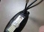
2 TUNDRA INTERIOR LIGHT UPGRADE Section II - Installation Procedure A. Check Kit Contents 1. Check kit for contentand damage.(fig. A1) Light Guide Switch B. Vehicle Preparation 1. Remove batterynegativeterminal. Harness replace 2. Apply protectivecovering to vehicle. Cup Holder 3. Set parking brake. Attachment LED Modules C. Remove center console 1. Remove cup insert. Fig. A1 i.. Grasp Cup holder insert and lift upward, and remove from vehicle. (Fig. C1) ii. Use panel safe tool. iii. At rear edge of center console insert pry upward. Remove upper console panel sub-assembly. Remove parking brake insert. Fig. C2 iv. Lift rear of centerconsole and slide towards rear. Remove from vehicle. (Fig. C3) Fig. C1 Fig. C2 Fig. C3 Fig. C4a BUCKET SEATkick panel fasteners. 2. Loosen front Loosen 2. kick screwdriver panel fasteners. i. Usingfront a phillips loosenfastenerwhile pulling outward.remove fastenerson bothsides. Using a phillips screwdriver loosen fastener i. (Fig. C4ab) while pulling outward. Remove fastenerson bothsides. (Fig C4ab) BENCH SEAT 3. Remove centerconsole screws i. Using phillips screwdriver remove screws as shown. (Fig. C5ab) ii. Pull forward to allow access to rear of cigarette lighter. SoutheastToyota Distributors, LLC Fig. C4b 2 of 9


 Fig. D3A Fig. D3a Fig. D3b Bench Seat 1.")

3 Toyota TUNDRA Interior Light Upgrade D. Install Harness Caution: Secure harness with pads and cable ties as needed, keep harness from touching hot or moving objects. LED PW SW LED 1. Lay out harness as shown and identify connectors. (Fig. D1) PW Power SW Switch LED Module CH Cup Holder SB Storage Box Fig. D2 D1 CH SB 2. Bulk of harness will reside under forward portion on center console beside shift assembly in floor shifter model. 3. Route storage box connector to the rear of the center console. i. Secure as needed. 4. Route LED connector to driver side of center console as shown. 5. Route LED connector to passenger side of vehicle. 6. Locate power. i. Locate Power outlet socket located in cargo box White with Black stripe negative, Gray positive. Fig. D3A Fig. D2 BUCKET SEAT BENCH SEAT H 17 Cigarette Lighter ii. Install T-Taps in a staggered fashion. (Fig. D3ab) Fig. D3A Fig. D3a Fig. D3b Bench Seat 1. Lay out harness as shown & identify connectors. (Fig. D2) 2. Bulk of harness will reside behind center console facia. 3. Attach harness to power. (Fig. D4) Attach Red T-Taps to gray wire (Pin# 1) and the White wire with he Black Strip (Pin# 2) on connector H 17 of the cigarettelighter circuit with H 17 pliers Cigarette Lighter Attach Red T-Taps to gray wire (Pin# 1) and the White wire with he Black Strip (Pin# 2) on connector H 17 of the cigarettelighter circuit with pliers SoutheastToyota Distributors, LLC 3 of 9
 1. Drill holes for storage box lights.")

 iv.")
 vi. Repeat using template labeled drivers side 2.")
 E5) Fig. E3 Fig. E4 3. 4.")

 for alignment. (Fig. F1ab) iii.")


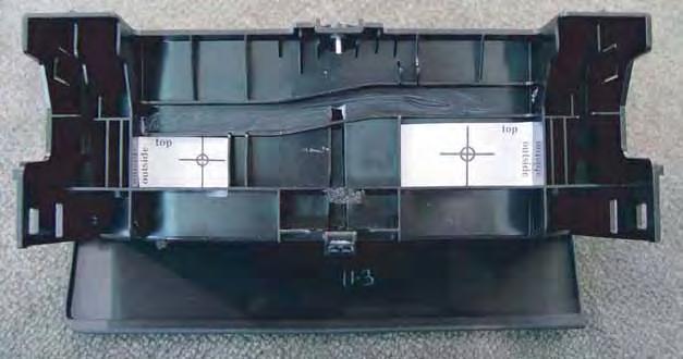
4 TOYOTA SEQUOIA TUNDRA INTERIOR LIGHT UPGRADE Section II - Installation Procedure E. Install Storage Box Box Lights BUCKET 1. Drill holes SEATS for storage box lights. Final installation should look as shown. (Fig. E1) 1. Drill holes for storage box lights. Final installation should i. Cut look out enclosed as shown. paper (Fig. template E1) labeled passenger side storage box. i. Cut out enclosed paper template labeled passenger Fig. E1 Fig. E2 Align template side bucket as seat shown storage use a box. punch/scribe ii. to mark the center of the hole to be drilled. ii. Align template as shown use a punch/scribe to (Fig. E2) mark the center of the hole to be drilled. (Fig. iii. E2) Drill pilot holes with 1/8 drill bit. (Fig. E3) iii. iv. Drill Finally pilot drill holes hole with with 1/8 a 9/32 drill bit. drill (Fig. bit. E3) iv. Finally De-burr drill holes hole with with de-burring a 9/32 tool. drill bit. v. vi. De-burr Repeat using holes template with de-burring labeled tool. drivers side storage box (Fig E4) vi. Repeat using template labeled drivers side 2. Insert bucket Lens seat from storage inside box of storage (Fig E4) box. (Fig. E5) Insert Firmly Lens press from LED inside assembly of storage into lens. box. (Fig. E6) E5) Fig. E3 Fig. E Firmly Use adhesive press LED pad to assembly secure wires. into lens. (Fig. (Fig. E7) E6) 4. Use adhesive pad to secure wires. (Fig. E7) Fig. E5 Fig. E6 F Install Cup Holder Lights. F BUCKET SEATS Install Cup Holder Lights. 1. Drill holes for cup holder lights 1. Drill holes for cup holder lights i. Cut out Bucket seat cup holder templates i. Cut out Cup holder templates ii. Align template as shown using edge of casting ii. Align template as shown using edge of casting for alignment. (Fig. F1ab) for alignment. (Fig. F1ab) iii. Use a punch/scribe to mark the center of the iii. Use punch/scribe to mark the center of the hole to be drilled. hole to be drilled. iv. Drill pilot holes with 1/8 drill bit. iv. Drill pilot holes with 1/8 drill bit. Allow drill bit to penetrate cup holder liner to Allow drill bit to penetrate cup holder to help help align holes. align holes. v. Drill the lamp hole with a 9/32 drill bit. v. Drill the lamp hole with 9/32 drill bit. vi. De-burr holes with de-burring tool. vi. De-burr holes with de-burring tool. 2. Insert lens from inside of cup holder box. 2. Insert lens from inside of cup holder box. Fig. E7 Fig. F1a REAR Fig. F1b FRONT 3. From the outside of the cup holder, install the LED s onto the lenses. Press firmly while holding the Lens Fig. F3a from the inside. (Fig. F3ab) Southeast Toyota Distributors, LLC 4 of 9 Southeast Toyota Distributors, LLC Page of 10 Fig. F3b


 5.")


 8. Reinstall cup holder insert. BENCH SEATS 1.")

 2.")

 iii.")
 v.")
 4.")
5 TOYOTA TUNDRA Section II - installation procedure 3. From the outside of the cup holder install the LED s onto the lenses. Press firmly while holding the lens from the outside. (Fig. F3ab) INTERIOR LIGHT UPGRADE 4. Use adhesive pad to secure wires. (Fig. F4) 5. Connect to cup holder Y lead on harness. 6. Reinstall center console. 7. Using previously drilled hole as a guide, drill or punch a 3/8 hole in the cup holder insert to allow light to pass through. A Unibit or step drill is recommended. (Fig. F5ab) 8. Reinstall cup holder insert. BENCH SEATS 1. Remove cup holder assembly i. Depress small tab on both sides of sliding cup holder assembly. (Fig. F6) ii. Remove cup holder assembly and orient as shown. (Fig. F7) 2. Drill holes for cup holder lights i. Cut out bench seat cup holder templates ii. Align template as shown using edge of casting for alignment. (Fig. F7) iii. Use punch/scribe to mark center of the hole to be drilled. iv. Drill pilot holes with 1/8 drill bit. (Fig. E3) v. Drill lamp hole with a 9/32 drill bit. 3. Insert lens from inside of cup holder box. (Fig. F8) 4. From the outside of the, install the LED s into the lenses. Press firmly while holding the lens from the inside. (Fig. F9) 5. Drill hole on tab on cup holder and secure the lamp assemblies wire harness to act as a strain relief. (Fig. F9) 6. Use adhesive pad to secure wires. (Fig. F10) BOTTOM EDGE Southeast Toyota Distributors, LLC 5 of 9

 i.")

 2.")


 (Fig. G1-G2) i.")


 secured to the crook in the support in the center")
 contact with the adhesive surface. Fig. G3 Fig.")

 v.")


6 TOYOTA TUNDRA /SEQUOIA INTERIOR LIGHT UPGRADE Section II - Installation Procedure INSTALL ADDITIONAL LIGHTS BENCH SEATS 1. Using photos locate where Lamps are to be placed. (Fig. F12ab ) i. Use a punch/scribe to mark the center of the hole to be drilled. Fig. F13a Fig. F13b ii. Drill pilot holes with 1/8 drill bit. iii. Drill the lamp hole with a 9/32 drill bit. (Fig. 13ab) 2. Insert lens from front of facia. Fig. F14a Fig. F14b 3. From the outside of the cup holder, install the LED s from the inside. (Fig. F14ab) G. Install Light Modules Guide 1. Install drivers Driver side Light light guide. Module. end into LED modules 2. Drill Locate hole attachment in air duct location as shown. as (Fig. indicated. G1) (Fig. G1-G2) i. Drill hole in lip of air duct as shown with 3. Clean 9/32 surface drill to bit. remove and wax. Fig. G1 Fig. G1 Fig. G2 Wire upward 3. Attach i. Wipe light application guide area clean with alcohol and a clean no-scratch cloth.(fig. G3) i. The inboard cable tie will be threaded through ii. Dry previously the installation drilled hole.. area using a clean, dry, lint free cloth. ii. Use cable ties to secure the light guide. (Fig. G2) 4. Using the pull tab remove the tape liner from the back iii. Out of board the switch cable plate. tie will (Fig. be G4) secured to the crook in the support in the center of the dash i. Avoid area. finger (Fig. G3) contact with the adhesive surface. Fig. G3 Fig. G1 Fig.G2 ii. iv. Press The light module guide firmly assembly against should surface. be orientated (Fig. G1) Secure module with screws. (Fig. G5) v. Fully tighten the wire ties and cut off excess Install passenger side Light Module. 4. Install passenger side light guide Remove passenger side shield by pressing in four iii. i. Cut The out light passenger guide assemblies side rod templates tabs located along front edge of should shield. be orienii. Align tempalte as shown using ribs for alignment. Locate LED (Fig. modules attachment G4a) positioned location toward as indicated. the center of (Fig. iii.drill the G6) vehicle. the lamp (Fig.G1) hole with 9/32 drill bit Secure Thread Light Light guide Module with lead cable through ties through shield. loops (Fig. located G6) below glove box. (Fig. G4b) G4ab) Final Repeat assembly steps G3 should through appear G5. as shown. (Fig.G5) Fig. G4 Fig. G3 Fig. G6 G4b Fig. G4b Southeast Toyota Distributors, LLC 6 of 9 Page 6 of 10 pages Southeast Toyota, Distributors, LLC Fig. G4a Fig. G5 Fig. G5 Fig. G5
 2. Drill hole for switch. i.")
 iii.")
, drill the switch")
 3.")

 5.")
 i. Avoid finger contact with the adhesive surface. 6.")
 ii.")
7 TOYOTA TUNDRA INTERIOR LIGHT UPGRADE H. Install power switch BUCKET SEATS 1. Final switch orientation. (Fig.H1) 2. Drill hole for switch. i. Cut out Bucket seat template ii. Align template as shown using edge of casting for alignment. (Fig.H2) iii. Use punch or scribe to mark center of the hole to be drilled. iv. Using a 1/2 drill bit (Unibit or step drill is highly recommended), drill the switch hole. BENCH SEATS 1. Final switch orientation. (Fig. H3ab) 2. Center switch hole between ribs. (Fig. H4) 3. Clean bezel surface to remove grease and wax. i. Wipe the application area clean with alcohol / water and a clean no-scratch cloth. ii. Dry the installation area using a clean, dry, lint free cloth. 4. Insert switch bezel into switch plate. (Fig. H5) 5. Using the pull-tab, remove the tape liner from the back of the switch plate. (Fig. H3) i. Avoid finger contact with the adhesive surface. 6. Using the bezel as a guide, install switch plate/be- zel into the previously drilled 1/2 hole. i. Align the printing ILLUMINATION square to the console. (Fig. H4) ii. Once aligned, press down firmly to adhere tape. 7. Install Sleeve to bezel, white edge of sleeve goes towards console. 5.7L (Fig. H7) NOTE: BENCH SEAT 5.7L Locate left knock out below heater control and mount switch in knock out and reinstall knock out. (Fig. H8) Fig. H8 Southeast Toyota Distributors, LLC 7 of 9

 2. Bundle up any excess wires and secure with cable tie. (Fig. I2) J.")

 for shipment. 6.")
8 TOYOTA TUNDRA INTERIOR LIGHT UPGRADE Section II - Installation Procedure 8. Install switch to bezel as shown. i. Using switch tool turn bezel clockwise to tighten. ii. Be careful not to over tighten as this will over ride the threads on the switch. If this happens simply retighten being careful not to over tighten. iii. Push button into bezel pressing to engage. (Fig. I5) I. Connect Switch to Harness 1. Connnect switch leads to harness. (Fig. I1) 2. Bundle up any excess wires and secure with cable tie. (Fig. I2) J. Post Installation 1. Reinstall interior. 2. Re-attach negative battery terminal, torque to 36 inch pounds. Fig. I1 J1 3. Clean LED modules with window cleaner and a non-scratch cloth. 4. Cycle test the system with the key in the ACC or ON position. The cycle may start from any step below but should cycle in this order. Fig. I2 i. All lights off. ii. Cup holder lights on only. iii. All lights on. iv. Interior Light on only. v. Back to step i. 5. The switch should be cycled to step i (all lights off) for shipment. 6. Place information card in glove box. Southeast Toyota Distributors, LLC 8 of 9 Page of 10 pages
9 TUNDRA INTERIOR LIGHT UPGRADE Check: Single UnoperationalModule Look for: Full engagementof affected LED moduleto LED wire harnesspigtail connector. Light guide insertedincorrectly (wrong end) No OperationalModules Full engagementof all LED moduleto LED wire harnesspigtail connectors. Power connection. Ground connection Switch connections Blown light kit fuse. (2 amp locatedundercenter console) Blown shift console illumination fuse (see vehicle owners manual for amperage and location.). SoutheastToyota Distributors, LLC 9 of 9
10 TOP TOP Drivers side storage box Passenger side storage box FLUSH TO BOTTOM OF BOX FLUSH TO BOTTOM OF BOX INSIDE Switch switch template 2 INCHES EDGE
11
Toyota Tacoma Interior Light Upgrade
 Toyota Tacoma 2011- Interior Light Upgrade Part Number 00016-00095 Accesory Code: IL2 Conflicts Kit Contents Item # Quantity Reqd. Description 1 1 Y Adapter 2 1 Wire harness 3 1 Hardware Kit 4 2 White
TOYOTA TACOMA LED BED LIGHTS Preparation
 Preparation Part Number: PT948-35160 Kit Contents Item # Quantity Reqd. Description 1 1 Hardware Kit 2 1 Driver Side LED assembly 3 1 Passenger Side LED assembly 4 1 Main Wire Harness Hardware Bag Contents
TOYOTA COROLLA EC REARVIEW MIRROR Section I Installation Preparation
 Section I Installation Preparation Part Number: PT374-02030 Section I Installation Preparation Kit Contents Item # Quantity Reqd. Description 1 1 AD Mirror Assembly w/compass & Maplights 2 1 Hardware Bag
TOYOTA TUNDRA 2015 BLACK TEXTURED FENDER FLARE
 TOYOTA TUNDRA 2015 BLACK TEXTURED FENDER FLARE Part Number: 00016-34083-02 Accessory Code: BF1000 Conflicts Note: Kit Contents Item # Quantity Reqd. Description 1 1 Left Front Fender Flare 2 1 Right Front
Conflicts Note: Drop-in Bed liner
 Toyota Tundra 2015 LED Bed Lights Preparation Part Number: 00016-34089 Accessory Code: BU1000 Conflicts Note: Drop-in Bed liner Kit Contents Item # Quantity Reqd. Description 1 1 Hardware Kit 2 1 Driver
TOYOTA TACOMA TRAILER WIRE HARNESS Preparation
 Preparation Part Number: PT725-35120 Kit Contents Item Quantity Reqd. Description # 1 1 Flasher Assembly (F/A) 2 1 Wire Harness 3 1 Sub Wire Harness 4 2 Plastic Tie (300mm) 5 4 Plastic Tie (200mm) 6 13
Bi-Color Signal Mirror Installation Instructions
 Bi-Color Signal Mirror Installation Instructions 2005-2009 Toyota Tacoma THE safety accessory of the 21 st Century. P/N 210-0141-0 Rev. A2 (3/30/09), BTV 2007 Muth Mirror Systems, LLC Page 3 of 13PplPage
Conflicts. TOYOTA Highlander 2015 Fender Flares Part Number: Accessory Code: BF7000. Safety Tools Safety Glasses
 Highlander 2015 Fender Flares Part Number: 00016-48016 Accessory Code: BF7000 Conflicts Note: Factory Splash Guards Kit Contents Item # Quantity Reqd. Description 1 1 Left Front Fender Flare 2 1 Right
Installation for Full Size Polaris Ranger Crew Doors
 Installation for Full Size Polaris Ranger Crew Doors Order of Installation: Heater Doors Wiper on to Windshield Windshield Top & Back Panel Note: Most of the steps in these instructions need to be repeated
TOYOTA CAMRY LIP SPOILER Preparation
 Preparation Part Number: PT29A-03070-XX Kit Contents 1 1 Lip Spoiler 2 1 Hardware Bag Hardware Bag Contents 1 2 M6 Nuts 2 2 M6 Bolts Additional Items Required For Installation 1 1 Installation Kit, P/N
TOYOTA Tundra 2014 Fender Flare Set
 2014 Part Number: 00016-34047 Accessory Code: TG1 Conflicts Note: Regular Cab Kit Contents Item # Quantity Reqd. Description 1 1 Left Front Fender Flare 2 1 Right Front Fender Flare 3 1 Left Rear Fender
TOYOTA TACOMA 2005 TRAILER WIRE HARNESS Preparation
 Preparation Part Number: 08921 04960 NOTE: Part number of this accessory may not be the same as the part number shown. Kit Contents Item # Quantity Reqd. Description 1 1 Converter Assembl y 2 1 Wire Harness
SCION tc 2005 PEDESTAL SPOILER Preparation. Part Number: PT47A XX PT47A XX PT47A XX
 Preparation Part Number: PT47A-21052-XX PT47A-21062-XX PT47A-21082-XX Kit Contents Item # Quantity Reqd. Description 1 1 Painted Spoiler Assembly 2 1 LH Gas Strut 3 1 RH Gas Strut 4 1 Hardware Bag Hardware
SCION FR-S REAR SPOILER Preparation
 Preparation Part Number: PT938-18130-XX Kit Contents Item # Quantity Reqd. Description 1 1 Spoiler 2 2 Strut 3 1 Hardware Bag Hardware Bag Contents Item # Quantity Reqd. Description 1 2 M6 x 1 Nut with
Part Number: ;-02;-03;-08;-10;-11;-18;-21
 Document # 4065 4/3/06 TOYOTA MATRIX 2006 - FENDER FLARES Section I Installation Preparation Part Number: 00016-12120-01;-02;-03;-08;-10;-11;-18;-21 Code: SF1 Kit Contents Item # Quantity Reqd. Description
TOYOTA TUNDRA 2007>> FENDER FLARE SET
 TOYOTA TUNDRA 2007>> FENDER FLARE SET Section I Installation Preparation Part Number: 00012-T0852- & 00012-T1052- Section I Installation Preparation Kit Contents Color Applicability/Trim Level Item Quantity
Signal Mirror Installation Instructions Toyota Tacoma
 Signal Mirror Installation Instructions 2005-2015 Toyota Tacoma THE safety accessory of the 21 st Century. P/N 210-0115-0 Rev. A4 (3/11/15), BTV 2005 Muth Mirror Systems, LLC Page 3 of 12PplPage 3 of 12
General Prisoner Transport Install Instructions PT-2-INST
 General Prisoner Transport Install Instructions PT-2-INST 50 or 60 high x 80, 100 & 120 inch long / Double Compartment Inserts Also refer to PT-A-3XX instructions for vehicle specific mounting measurements
C6 Corvette Rear Spoiler Kit CDC #
 2005 2008 C6 Corvette Rear Spoiler Kit CDC # 0542 7002 01 Note: Read installation instructions before starting Kit Includes: 1 C6 Rear Spoiler 2 CHMSL Bracket # 0542-3500-01 2 Screw 4.2 x 1.41 x 25 # 30005
STYLE BAR & TONNEAU COVER INSTALLATION
 STYLE BAR & TONNEAU COVER INSTALLATION INSTALLATION MANUAL: 2005 to '09 Mustang P/N: 10-8002-C12071B Saleen Performance, Inc. 1225 East Maple Rd., MI 48083 800-888-8945 www.saleen.com 1 IF YOU ARE NOT
Signal Mirror Installation Instructions Honda Odyssey
 Signal Mirror Installation Instructions 2005-2009 Honda Odyssey THE safety accessory of the 21st Century. P/N 210-0122-0 Rev. A4 (6/9/09), BTV 2006 Muth Company, LLC PROFESSIONAL INSTALLATION RECOMMENDED
GENUINE PARTS INSTALLATION INSTRUCTIONS
 GENUINE PARTS INSTALLATION INSTRUCTIONS 1. 2. 3. 4. DESCRIPTION: APPLICATION: PART NUMBER: KIT CONTENTS: Kit G Coupe 999J2 JxxxxB4 (xxxx Designates model year and color) Item Qty. Description Part Number
Toyota Sienna IPod Interface
 Toyota 2011 - IPod Interface Part Number: 00016-00117 Accessory Code: RI40 Conflicts 1. Radios equipped with USB input jack 2. ipod Shuffle General Applicability Radio model numbers (Use "SAT" button)
GENUINE PARTS INSTALLATION INSTRUCTIONS
 GENUINE PARTS INSTALLATION INSTRUCTIONS DESCRIPTION: APPLICATION: PART NUMBER: REAR SPOILER KIT - CARBON FIBER INFINITI Q60 T99J1 5CH0B KIT CONTENTS: Item Qty. Part Description A 1 Spoiler Assembly B 4
GENUINE PARTS INSTALLATION INSTRUCTIONS
 GENUINE PARTS INSTALLATION INSTRUCTIONS DESCRIPTION: APPLICATION: PART NUMBER: Interior Accent Light (Multi-color) MURANO, MURANO CROSS CABRIOLET(2011) Interior Accent Light (Multi-color) (B64D0 1SX0A)
TOYOTA MATRIX FENDER FLARES
 Document # 2880 Created 11/29/04 TOYOTA MATRIX 2005 - FENDER FLARES Section I Installation Preparation Part Number: 00016-12120-01;-02;-03;-08;-10;-11;-18;-21 Code: SF1 Kit Contents Item # Quantity Reqd.
Installation instructions, accessories. TV receiver, digital
 Installation instructions, accessories Instruction No 30756561 Version 1.1 5 Part. No. 30756181, 30756569 TV receiver, digital Volvo Car Corporation TV receiver, digital- 30756561 - V1.1 Page 1 / 36 Equipment
* * APPLICABLE MODELS: 2014 > MAZDA 3
 PART NUMBER: 0000 8C L46 GENUINE ACCESSORIES INSTALLATION INSTRUCTIONS Rev. AAA *550-0604-000* APPLICABLE MODELS: 204 > MAZDA 3 REQUIRED COMPONENTS: ITEM QTY DESCRIPTION Usage Chart MIRROR ASSEMBLY: Mirror
Signal Mirror Installation Instructions
 Signal Mirror Installation Instructions 2006 2007 Honda Ridgeline THE safety accessory of the 21 st Century. P/N 210 0142 0 Rev. A (9/5/07), BTV 2007 Muth Company, LLC Professional Installation Recommended:
TOYOTA TACOMA ROOF RACK Preparation. Part Number: PT
 Preparation Part Number: PT278-35140 Kit Contents Item # Quantity Reqd. Description 1 1 LH Base Rail Assembly w/ Crossbar 2 1 RH Base Rail Assembly 3 1 Hardware Bag 4 2 Brackets 5 1 Front Crossbar Assembly
Signal Mirror Installation Instructions Dodge Charger, Dodge Magnum, Chrysler 300
 Signal Mirror Installation Instructions 2006-2009 Dodge Charger, 2005-2008 Dodge Magnum, 2005-2009 Chrysler 300 THE safety accessory of the 21st Century. P/N 210-0123-0 Rev. A4 (10/7/09), BTV 2007 Muth
Arc Trainer Main Frame Assembly
 Arc Trainer Main Frame Assembly Kit No. 610AK019-4 Kit No. 630AK019-4 NOTE: This instruction sheet describes how to replace the main frame assembly in the Arc Trainer 610A. Tools Required 3/16 Allen wrench
GENUINE ACCESSORIES INSTALLATION INSTRUCTIONS. ITEM QTY DESCRIPTION Usage Chart
 PART NUMBER: 0000 8C R0 GENUINE ACCESSORIES INSTALLATION INSTRUCTIONS Rev. AAA *550-0554-000* APPLICABLE MODELS: 203 > CX-5 REQUIRED COMPONENTS: ITEM QTY DESCRIPTION Usage Chart MIRROR ASSEMBLY: Mirror
LED Cup Holder Lights Installation Guide
 LED Cup Holder Lights Installation Guide (20112015 Kia Optima) Thanks for purchasing this LED Cup Holder Light Kit! If you have any questions or feedback please email us direct at Sales@K5OptimaStore.com
Isuzu D-Max Part Numbers Black Polished
 SB007 Sports Bar Fitting Instructions Isuzu D-Max 0 Part Numbers - 55000 - Black - 5000 - Polished Installation Time: 0 min (Approximately) PLEASE KEEP INSTRUCTIONS IN GLOVE BOX FOR FURTHER USE RECOMMENDED
Bushwacker Jeep Flat Style Fender Flares Front Pair
 Bushwacker Jeep Flat Style Fender Flares Front Pair Note: These instructions involve cutting parts of your vehicle. Please read all instructions prior to starting. Installation Time: 3-4 Hours Tools Required:
Page No. 1 of 15. Issue F: 11/ FI
 MY09 FORESTER SUV CARGO BARRIER Installation Instructions Part Number 705400/425 705400 -To Suit Non Sunroof models only 705425 To suit Sunroof models only Production From March 2008 to Dec. 2012 This
Bushwacker Jeep Flat Style Fender Flares Rear Pair (JK Wrangler 2dr)
") Bushwacker Jeep Flat Style Fender Flares Rear Pair (JK Wrangler 2dr) Note: These instructions involve cutting parts of your vehicle. Please read all instructions prior to starting. Installation Time: 3-4
Bushwacker Jeep Flat Style Fender Flares Rear Pair (JK Wrangler 2dr) Note: These instructions involve cutting parts of your vehicle. Please read all instructions prior to starting. Installation Time: 3-4
Conflicts Note: None. TOYOTA Highlander 2016 LED Illumination Package (Interior and Exterior) Part Number: Accessory Code: LL1000
 Part Number: Accessory Code: LL1000") TOYOTA Highlander 2016 LED Illumination Package (Interior and Exterior) Part Number: 00016-00069 Accessory Code: LL1000 Conflicts Note: None Color Applicability/Trim Level Kit Contents Item # Quantity
TOYOTA Highlander 2016 LED Illumination Package (Interior and Exterior) Part Number: 00016-00069 Accessory Code: LL1000 Conflicts Note: None Color Applicability/Trim Level Kit Contents Item # Quantity
Rusty s JL Winch Mount RR-WM55-JL INSTALLATION INSTRUCTIONS
 Rusty s JL 2018+ Winch Mount RR-WM55-JL INSTALLATION INSTRUCTIONS Introduction: Rusty s recommends that this installation be performed by a certified automotive technician or a person with professional
PROVEN WORLDWIDE SNORKEL FOR CHEVY COLORADO NEW PRODUCT
 AEV30272AC Last Updated: 10/09/18 PROVEN WORLDWIDE SNORKEL FOR CHEVY COLORADO NEW PRODUCT Please visit www.aev-conversions.com to view the most current installation guide for this product. This is a new
TOYOTA TACOMA BED EXTENDER Preparation. Part Number: PT
 Preparation Part Number: PT392-35120 Kit Contents 1 1 Curved Tube Assembly - Right 2 1 Curved Tube Assembly - Left 3 3 Center Tube 4 1 Hardware Bag 5 1 Installation Instructions 6 1 Care Card Hardware
w w w. h d o n l i n e s h o p. d e VRSCF RIGID SADDLEBAGS GENERAL PREPARATION -J04704 REV Kit Number Models Tools and Supplies Required
 -J070 REV. 00-0- VRSCF RIGID SADDLEBAGS GENERAL Kit Number 7-0 Models For model fitment information, see the P&A retail catalog or the Parts and Accessories section of www.harley-davidson.com (English
Fig. 1 Fig. 2. Fig. 3 Fig. 4 TOOLS REQUIRED: *Phillips Screwdriver *Three Inch Putty Knife*Panel Removal Tool *10mm Nut Driver CONTENTS:
 *Phillips Screwdriver *Three Inch Putty Knife*Panel Removal Tool *10mm Nut Driver CONTENTS: 2EA. 6X9 TWO WAY SPEAKERS P/N 05030281AA 1EA. INSTRUCTIONS P/N RBI05LXREAR 300c and Charger 1. Remove the lower
Side and rear window, assembly overview
 64-7 Side and rear window, assembly overview 1 - Side/rear window Removing Unbroken Page 64-9 Broken Page 64-11 Installing Page 64-13 Curing time Page 64-21 Re-sealing Page 64-25 2 - PUR adhesive sealant
All Terrain Flares 2014 Chevy Silverado
 Page 1/8 Components: 1. Front Flares (2) 2. Rear Flares (2) Tools required: - Utility knife - #2 Phillips driver - Socket wrench - 13 mm Socket - 6 mm Allen Wrench - T-15 Torx bit - Trim Removal Tool -
INSTALLATION MANUAL REAR PARKING ASSIST SENSORS
 MITSUBISHI MOTORS GENUINE ACCESSORIES PART NUMBER MZ380456EX APPLICABLE MODEL LANCER SEDAN INSTALLATION MANUAL REAR PARKING ASSIST SENSORS Thank you for purchasing MITSUBISHI genuine * REAR PARKING ASSIST
TOYOTA TUNDRA CARGO DIVIDER Preparation. Part Number: PT
 Preparation Part Number: PT767-34070 Kit Contents 1 1 Divider Screen 2 1 LH Bracket with Warning Label 3 1 RH Bracket without Warning Label NOTE: Part number of this accessory may not be the same as the
TOYOTA PRIUS BODY SIDE MOLDING Preparation
 Preparation Part Number: PT938-47160-XX Kit Contents Item # Quantity Reqd. Description 1 1 Molding, LH Front Door 2 1 Molding, LH Rear Door 3 1 Molding, RH Front Door 4 1 Molding, RH Rear Door Hardware
MIL-STD B (SH) UPDATE
 UPDATE") MIL-STD-2042-5B (SH) UPDATE Method 5A1 Insert Equipment and materials (to be added to table 5A1-I) Pliers 3.2.2.2 Cable and fiber preparation for Fiber Systems International backshells. Step 1: Ensure
MIL-STD-2042-5B (SH) UPDATE Method 5A1 Insert Equipment and materials (to be added to table 5A1-I) Pliers 3.2.2.2 Cable and fiber preparation for Fiber Systems International backshells. Step 1: Ensure
Signal Mirror Installation Instructions
 Signal Mirror Installation Instructions 2005-2010 Chevy Corvette C6 THE safety accessory of the 21 st Century. P/N 210-0144-0 Rev. A3 (9/29/2011), BTV 2007 Muth Mirror Systems, LLC Page 3 of 10PplPage
TOYOTA TACOMA BED EXTENDER Preparation. Part Number: PT General Applicability All 2012 and newer Tacoma models
 Preparation Part Number: PT392-35120 Kit Contents 1 1 Curved Tube Assembly - Right 2 1 Curved Tube Assembly - Left 3 3 Center Tube 4 1 Hardware Bag 5 1 Installation Instructions 6 1 Care Card Hardware
INSTALLATION INSTRUCTIONS
 INSTALLATION INSTRUCTIONS Accessory Application Publications No. BII 25829 2004 MDX Issue Date SEP 2003 PARTS LIST Tailgate spoiler Right cover Left cover 2 Flat-head screws 2 Turn nuts TOOLS AND SUPPLIES
ACCESS COVER INSTALLATION INSTRUCTIONS (Kit #601 for 2006 Honda Ridgeline)
") ACCESS COVER INSTALLATION INSTRUCTIONS (Kit #601 for 2006 Honda Ridgeline) NOTE TO INSTALLER: IMPORTANT READ BEFORE ATTEMPTING INSTALLATION. Allow extra time, up to 2 hours to install this cover. Disassembly
ACCESS COVER INSTALLATION INSTRUCTIONS (Kit #601 for 2006 Honda Ridgeline) NOTE TO INSTALLER: IMPORTANT READ BEFORE ATTEMPTING INSTALLATION. Allow extra time, up to 2 hours to install this cover. Disassembly
Installation Instructions
 Installation Instructions Follow these simple instructions to install your OneDayCab! IMPORTANT: Unpack and check shipment for damage. Verify color, size and parts before demolition. Installation of interiors
BOX-117 E-Z-Go RXV Utility Box Mounting Kit Installation Instructions
 BOX-117 E-Z-Go RXV Utility Box Mounting Kit Installation Instructions Contents of BOX-117 Utility Box Mounting Kit: a (1 ea.) Utility Box Support Frame, Driver Side b (1 ea.) Utility Box Support Frame,
C4 Fabrication Rock Slider Installation 14+ 5th Gen 4Runner w/o KDSS
 C4 Fabrication Rock Slider Installation 14+ 5th Gen 4Runner w/o KDSS Thank you for your purchase of the C4 Fabrication s 5th Gen 4Runner Rock Sliders! This product was carefully crafted to ensure a perfect
BOX-118 E-Z-Go TXT Utility Box Mounting Kit Installation Instructions
 BOX-118 E-Z-Go TXT Utility Box Mounting Kit Installation Instructions Contents of BOX-118 Utility Box Mounting Kit: a (1 ea.) Utility Box Support Frame, Driver Side b (1 ea.) Utility Box Support Frame,
Installation and Assembly - Universal Articulating Swivel Double-Arm for 42" - 60" Plasma Screens
 Installation and Assembly - Universal Articulating Swivel Double-Arm for 42" - 60" Plasma Screens Models: PLAV 70-UNL, PLAV 70-UNL-S PLAV 70-UNLP, PLAV 70-UNLP-S R This product is UL Listed. It must be
FORD ESCAPE/KUGA SUV CARGO BARRIER INSTALLATION INSTRUCTION
 This cargo barrier is capable of being located in two positions, behind the 2nd row of seats with the seats in an upright position, and behind the 1st row of seats with the 2nd row of seats in their folded
TOYOTA RAV DOOR SILL PROTECTOR Preparation
 Preparation Part Number: PU060-42141-P1 Kit Contents 1 2 Door Sill (w/logo) 2 2 Rear Door Sill (w/graphic) Hardware Bag Contents Additional Items Required For Installation 1 2 3 Conflicts Note: Recommended
7878 K940. Checkpoint Antenna. Kit Instructions. Issue B
 7878 K940 Checkpoint Antenna Kit Instructions Issue B Revision Record Issue Date Remarks A July 7, 2009 First issue B Nov2013 Revised the Checkpoint installation procedures for 7878 and 7874 scanners Added
Signal Mirror Installation Instructions
 Signal Mirror Installation Instructions Honda CRV 1997-2003 THE safety accessory of the 21 st Century. P/N 210-0032-0 Rev B2 (6-26-04), GG 2003 Muth Mirror Systems, LLC. Note: Professional Installation
INSTALLATION INSTRUCTIONS
 INSTALLATION INSTRUCTIONS Accessory Application Publications No. AII 33380 SIDE S 2007 S2000 Issue Date AUG 2006 PARTS LIST Left upper side strake 2 Grommets 2 Butyl O-rings 2 Washer-screws, 6 x 20 mm
U.S. Rack, Inc Falcon Drive, Madera, CA APR17 INSTALLATION AND USE INSTRUCTIONS for SIDE-MOUNT LADDER RACK
 U.S. Rack, Inc. 2850 Falcon Drive, Madera, CA 93637 15APR17 INSTALLATION AND USE INSTRUCTIONS for SIDE-MOUNT LADDER RACK WARNING: Do NOT attempt to install or use this rack without following all instructions.
Flat Style Fender Flares Rear Pair. Jeep. Included in Hardware Kit:
 Jeep Flat Style Fender Flares Rear Pair STEP 1 PRIOR TO INSTALLATION A) Bushwacker only approves installing the fl ares according to these written instructions with the hardware provided. WARNING: Failure
Signal Mirror Installation Instructions
 Signal Mirror Installation Instructions Toyota RAV4 1996-2000 THE safety accessory of the 21 st Century. P/N 210-0034-0 Rev B1 (11-19-02), GG 2002 Muth Co. LLC. Note: Professional Installation Recommended
Installation Instructions Kit, Base Rail Bracket Part # 31413
 Installation Instructions Kit, Base Rail Bracket Part # 31413 Dealer / Installer: Provide a copy of these Instructions to the end user of this product. These Instructions provide important operating and
CHEVY/GMC SuperRail Mounting Kit #3117
 CHEVY/GMC SuperRail Mounting Kit #3117 #3100 SuperGlide (12K) Gross Trailer Weight (Maximum) Vertical Load Weight (Max. Pin Weight) 12,000 lbs. 3,000 lbs. Installation Instructions SPECIFICATIONS Fits
Kawasaki Teryx 750 Cab Kit* Caution: Before using this product, read this manual and follow all Safety Instructions.
 Owner s Manual Model: Kawasaki Teryx 750 Kawasaki Teryx 750 Cab Kit* Caution: Before using this product, read this manual and follow all Safety Instructions. Safety Instructions Cab Kit Contents Hardware
Installation and Assembly: Full Service Video Wall Mount
 Installation and Assembly: Full Service Video Wall Mount Model: DS-VW765-LAND Max UL Load Capacity: 125 lb (57 kg) 1 of 12 ISSUED: 05-13-11 SHEET #: 145-9011-5 05-21-12 Note: Read entire instruction sheet
Signal Mirror Installation Instructions
 Signal Mirror Installation Instructions 2004 2008 Ford F-150 XLT, FX4, & Lariat Pre-wired without side signals Pre-wired with side signals Without side directional lights, see page 2 With side directional
KWIK-KIT KK-S INSTALLATION INSTRUCTION PACKAGE
 KWIK-KIT KK-S-120-02 INSTALLATION INSTRUCTION PACKAGE INSTALLATION INSTRUCTIONS HAVIS KWIK-KIT KK-S-120-02 2002-2007 DODGE/FREIGHTLINER SPRINTER VAN PLEASE READ COMPLETE INSTRUCTIONS PRIOR TO INSTALLATION
INSTALLATION INSTRUCTIONS
 INSTALLATION INSTRUCTIONS Trans4mer Grille Guard/Winch Mount Kit 645 For Chevrolet Silverado 500HD & 3500 This WARN Trans4mer system can be customized to give your Chevy Silverado a wide variety of looks,
Rugged Ridge Body Armor Guard Kit, 5 Pieces, Black (07-Current JK 4-door)
") Rugged Ridge Body Armor Guard Kit, 5 Pieces, Black (07-Current JK 4-door) Installation Time: 60 Minutes Tools Required: Notes: Phillips head screwdriver 3/8 socket or Flat head screwdriver 1/2 socket 7
Rugged Ridge Body Armor Guard Kit, 5 Pieces, Black (07-Current JK 4-door) Installation Time: 60 Minutes Tools Required: Notes: Phillips head screwdriver 3/8 socket or Flat head screwdriver 1/2 socket 7
IMPORTANT! Recommended Tools. 7/16 Deep socket Phillips screwdriver
 IMPORTANT! Read all instructions carefully before commencing any work. Always wear proper safety equipment. Some installation steps will require two or more installers. Recommended Tools Ratchet 10-mm
Installation and Assembly: Flat Video Wall Mount For 40" to 65" Flat Panel Displays
 Installation and Assembly: Flat Video Wall Mount For 40" to 65" Flat Panel Displays Model: DS-VW665 Maximum Load Capacity: 125 lb (57 kg) 1 of 11 ISSUED: 03-22-12 SHEET #: 125-9288-4 06-25-13 NOTE: Read
STELLA AUTO SIDECAR INSTALL INSTRUCTIONS
 STELLA AUTO SIDECAR INSTALL INSTRUCTIONS Open crate and inspect sidecar Remove cardboard box from inside the sidecar Remove all hardware holding the sidecar to the crate Remove sidecar from crate Remove
Installation Instructions
 For Medium (15-18.5K) + Heavy duty (22-28.5K) Air Conditioner READ BEFORE INSTALLING UNIT To avoid risk of personal injury, property damage, or product damage due to the weight of this device and sharp
WOLF PUP LOOM TM & WOLF PUP LT LOOM TM
 WOLF PUP LOOM TM & WOLF PUP LT LOOM TM Assembly Instructions FL3000 FL3006 FL3009 WOLF PUP WOLF PUP LT Find out more at schachtspindle.com Schacht Spindle Company 6101 Ben Place Boulder, CO 80301 p. 303.442.3212
Jeep Wrangler JK & 4-Door Front Pair Part # Revision H
 Jeep Wrangler JK 2007 2 & 4-Door Front Pair Part # 10045 Revision H 03-25-09 Step 1: Prior to Installation: A) Bushwacker only approves installing the flares according to these written instructions with
INSTALLATION INSTRUCTIONS
 INSTALLATION INSTRUCTIONS SOLID PHENOLIC TOILET PARTITIONS 1080 DuraLineSeries Class-A Fire Rated Includes Institutional Hardware Option.67 IMPORTANT: Storage and Handling Information on last page. Review
Repair Instructions. Replacing a La Z Time Mechanism Side Subassembly. Remove the Back(s): Remove the Mechanism Assembly: CAUTION.
: Remove the Mechanism Assembly: CAUTION.") Replacing a La Z Time Mechanism Side Subassembly Tools Required: Slotted Screwdriver Power Driver 8" Driver Extension Ruler Note: Extension springs are not typically used on non-chaise standard width styles,
Replacing a La Z Time Mechanism Side Subassembly Tools Required: Slotted Screwdriver Power Driver 8" Driver Extension Ruler Note: Extension springs are not typically used on non-chaise standard width styles,
BABY WOLF LOOM. Assembly Instructions for Knocked-Down Looms
 BABY WOLF LOOM Assembly Instructions for Knocked-Down Looms BEFORE YOU BEGIN Please read through the directions before beginning to assemble your loom. Unpack the loom parts carefully. Do not throw away
Assembly Instructions Nevins Phone Booth
 Assembly Instructions Nevins Phone Booth Included Hardware Tools Required supplied by installer Drill & Bit Bolt A - (16) 1/4-20 x 1-1/2 hex head Bolt B - (20) 1/4-20 x 2-1/2 phillips head Screw 1 - (24)
OpenROV. Guide 3 - Electronics. We will now move to the assembly of the electronics that will control the ROV. Written By: OpenROV
 OpenROV Guide 3 - Electronics We will now move to the assembly of the electronics that will control the ROV. Written By: OpenROV 2017 openrov.dozuki.com Page 1 of 33 INTRODUCTION We will introduce soldering
RBP-1215B-RX DODGE RAM QUAD CAB RX3
 RBP-1215B-RX3 2002-2017 DODGE RAM 15-3500 QUAD CAB RX3 Passenger side RX-3 Side Step Drill Template Passenger side rear Modular Bracket (6) L Support Brackets Driver side rear Modular Bracket Driver side
GMC Cut-Out Fender Flares Set of 4
 GMC Cut-Out Fender Flares Set of 4 STEP 1 PRIOR TO INSTALLATION A) Bushwacker only approves installing the fl ares according to these written instructions with the hardware provided. WARNING: Failure to
Installation and Assembly - Universal Articulating Swivel Double-Arm for 42" - 60" Plasma Screens
 Installation and Assembly - Universal Articulating Swivel Double-Arm for 42" - 60" Plasma Screens Models: PLAV 70-UNL, PLAV 70-UNL-S PLAV 70-UNLP, PLAV 70-UNLP-S R This product is UL Listed. It must be
EmagiKit. Privacy Pod Plus. Quiet. Easy. Affordable. INSTRUCTIONS ASSEMBLY
 EmagiKit Privacy Pod Plus Quiet. Easy. Affordable. INSTRUCTIONS ASSEMBLY DIMENSIONS AND COMPONENTS 47 47 Ceiling Unit 2-B 2-L 2-R Glass Door Corner Trim Door Handle 90 Adjustable Height Work Surface 1-B
GMC Cut-Out Fender Flares Set of 4
 GMC Cut-Out Fender Flares Set of 4 STEP 1 PRIOR TO INSTALLATION A) Bushwacker only approves installing the fl ares according to these written instructions with the hardware provided. WARNING: Failure to
INSTALL/REMOVAL INSTRUCTIONS: WINDOW REGULATOR
 REMOVAL/INSTALL OF WINDOW REGULATOR (741-584) Ford Focus 2000-2007 General Tech Tips: Use painter s tape rather than duct tape to secure window. It will not damage paint or leave sticky residue. A plastic
INSTALLATION INSTRUCTIONS
 3b Fig. A Fig. C Fig. B Fig. D KIT FEATURES ISO and DIN unit provisions Pocket (holds jewel cases) KIT COMPONENTS Radio Housing 99-7898 INSTALLATION INSTRUCTIONS APPLICATIONS ACCORD 990-97, CIVIC 999-00,
Be sure any accessory used will fit with the soft upper doors before installing. Not all accessories will be compatible.
 Company Name: Spike Power Sports Vehicle Name: Polaris General 2P Product Description: Soft Upper Doors Part Number: 58-1600 Revision: R01 09/19/2018 Contents: 655 Elm Ridge Ave, Canal Fulton OH, 44614
Ribcage Installation. Part 2 - Assembly. Back-Bone V1.06
 Ribcage Installation Part 2 - Assembly Back-Bone V1.06 Contents Section 1 Before You Get Started... 2 Included With Your Kit:... 2 Figure: A... 3 CAUTION!... 4 Note:... 4 Tools Required... 5 Section 2:
Product must be installed as shown using the screws and brackets provided. Use of incorrect hardware could result in damage to the product.
 General Notes These installation instructions are intended to be comprehensive for a typical Keyeira/Presto configuration. Your configuration may differ. If you have questions contact Geiger Customer Service
CHEVY/GMC SuperRail Mounting Kit #4423
 CHEVY/GMC SuperRail Mounting Kit #4423 #4100 SuperGlide (16K) #4400 SuperGlide (20K) Gross Trailer Weight (Maximum) Vertical Load Weight (Max. Pin Weight) 16,000 lbs. 4,000 lbs. Gross Trailer Weight (Maximum)
Fortress Fe Posts must always be secured to the deck framing. Fortress Fe Posts should never be attached to only the deck boards.
 Installation Instructions for FortressCable H-Series Stair Panels with Simplified Stair Bracket SSB-05 and Fe Posts It is the responsibility of the installer to meet all code and safety requirements, and
1. VERIFY ALL COMPONENTS
 R INSTALLATION INSTRUCTIONS RAGNAR+ODEN FACE MOUNT, BYPASSING. VERIFY ALL COMPONENTS BASE KIT Track stand-offs Front trolley kit * Rear trolley kit * Allen keys Track fastener kit - wood - Bottom guide
TOYOTA MOTOR EUROPE CA Products Division Tel : Fax :
 TOYOTA MOTOR EUROPE CA Products Division Tel : + 32 2 745 26 77 Fax : + 33 2 745 26 99 Ordering part numbers Comments Part Numbers Wooden floor one hatch PZ449-D3C42-11 one hatch with carpet PZ449-D3C42-01