Santa Fe Cover INSTALLATION GUIDE. Alumawood TM Newport with MAXX Panel TM Installation Guide
|
|
|
- Hannah Garrett
- 6 years ago
- Views:
Transcription

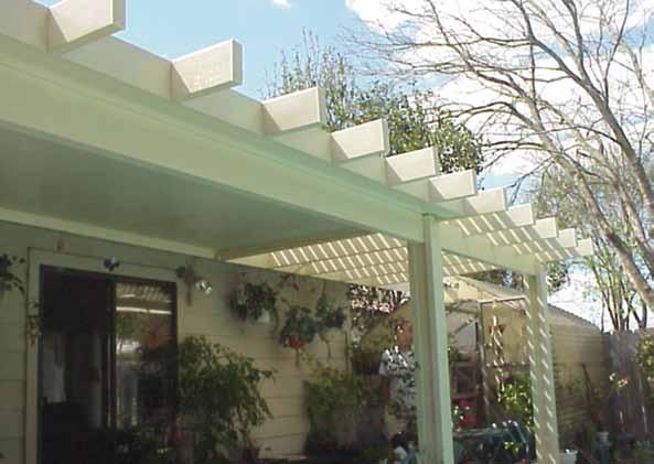
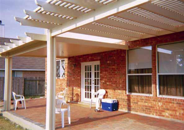
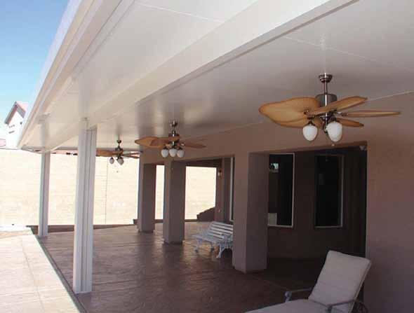
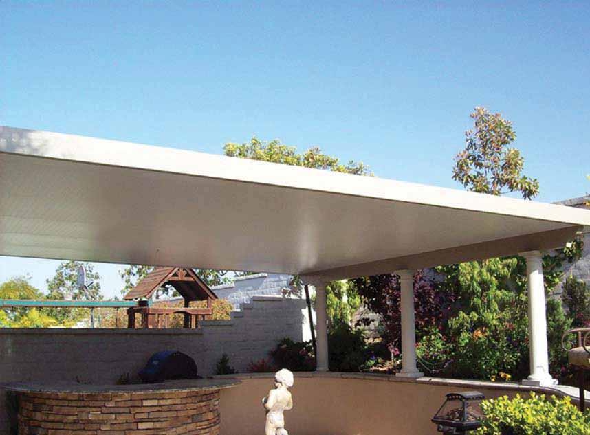
1 Alumawood TM Newport with MAXX Panel TM Installation Guide Santa Fe Cover INSTALLATION GUIDE Whatever the weather, you can enjoy the sophisticated charm of a lattice cover. The Santa Whatever the weather, you can enjoy your outdoor living space with a sense of security. The Fe Package combines the solid roof construction of Aluamwood TM Newport with MAXX Panel TM package combines the elegant charm of an Alumawood TM Newport the Snap-N-Lock patio structure TM Insulated with the strength Panel of with the beautiful patented Snap-N-Lock TM Insulated Panel. Southwest lattice accents and exposed rafter tails. For maximum protection from the elements, run the panels the entire length of the roof. To provide shade and allow refreshing breezes to pass through, extend the solid roof only partway. w w w. a l u m a w o o d. n e t
2 Existing Fascia or Structure 3 Wall Header Rafter Bracket 2 x 6 Side Rafter Valance Fascia 3 Snap-N-Lock Insulated Panel 3 Extruded Gutter Rafter Tail Rafter End: Mitered, Beveled, Corbel, Scalloped 2 x 6 Fascia Cover 3x8 Beam Top Post Bracket 3x3 Post 2 x 6 Post Plate Bottom Post Bracket
3 1. Install Wall Header A. Select mounting area on wall. Snap a level chalkline along the wall to locate the bottom of the wall header. Remember, for proper drainage, the panels must be installed at a minimum 1/2 slope per foot of projection. B. Cut wall header to length. Level extrusion and mark position. C. Run two beads of caulking along the back surface of the box header where it will meet the existing building or fascia board. Extruded header is recommended for maximum strength. D. Position the header against the existing building and secure into place using two #10 x 1-1/2 hex head screws every 12 on center. If attached to 1 fascia board, use two #10 x 2 hex head screws in place of #10 x 1-1/2 screws at all rafter tails. If attached to a masonry wall, the header should be fastened with one 1/4 diameter masonry anchor every 16 on center. If enough room, apply a heavy bead of caulking along the top of the header to insure a water tight seal. Caulk House House Optional: Apply caulk at top of header, if enough room is available. Optional: Apply caulk at top of header, if enough room is available. Caulk Mobile Home Caulk Optional: Apply caulk at top of header, if enough room is available
4 2. Post Bracket Installation and Post Attachment A. Posts should be plumb and bottom cut off if necessary to adjust the pitch of the panels for proper drainage and, at the same time, to adjust the header so that it is level from end to end. (Recommended roof pitch is 1/2 for each 1 foot of panel length.) B. With the posts cut to length, plumb them again and mark the slab attachment. The anchors should be at least 4 away from the edge of the slab or expansion joint and 30 away from any crack. Two 3/8 holes should be drilled through the post brackets and corresponding holes 2-1/2 deep into the slab. Attach the brackets to the slab using the concrete anchors and hammering them into the concrete making sure not to damage the threads. C. Next, fit each post onto its bracket and fasten with four #14 x 3/4 painted sheetmetal or self-drilling screws. Post Level Wall Header #14x3/4 screws Post Bracket Slab Chalkline Anchor Bolts a. Drill 3/8 hole with the masonry bit at least 3 deep. b. Clean hole by blowing out debris. c. Drive the concrete anchor bolt far enough into hole so that at least six threads are below the surface. Do not damage threads. d. Tighten to 7 foot lbs. with a torque wrench or 2 to 3 turns from finger tight position to achieve the proper anchor setting. 3. Install Beam A. Set the 3x8 beam on top of the posts. Make sure the seam side is up and lines up with the wall hanger on the ledger board. B. Level the beam. C. Attach the post to the beam using the bracket as shown. #14x3/4 screws #14x3/4 screws - 3 -
5 4. Install Sideplates on Posts Note: Sideplates should be stuffed with foam. A. Place the sideplate so that it is centered on the post. Measure 12 from the bottom of the sideplates and drill a 5/8 hole through one side and the foam, making sure not to puncture the other side or dent the sideplate. B. Place a #14 x 3/4 sheetmetal screws through the sideplate into the post. C. Measure and mark up 24 on center. Drill a 5/8 hole. D. Use a level to make sure the sideplate is centered on the post and plumb. E. Place a #14 x 3/4 sheetmetal screws through the remaining holes. F. Drill four holes into the sideplates as done previously but for the header/sideplate attachment. (As shown) G. Place a #14 x 3/4 sheetmetal screws into the four holes. H. Place the 5/8 plugs into the holes. I. Repeat these steps on the opposite side and for all remaining posts. 3x8 Beam 2 x6.5 Side Plate w/ Foam Insert 5/8 Dia. Holes Level 5/8 Dia. Holes - 4 -
6 5. Install Snap-N-Lock Panels A. Place the first panel into position with the female side facing the outward perimeter of the structure. To avoid scratches on the interior side you have two options: 1.) Roof panels can be lifted over the wall sections top side down, and then turned over when in position. 2.) Cardboard end caps or carpet pieces can be draped over the top channel, so that the panels don t brush against the metal surface. Check the panel for proper depth in the header and square up to support walls. B. Fasten panel to the top and bottom of the box header with #8 x 9/16 Tek screws 8 on center. C. The front and side walls are fastened using a special #10 hex head sheetmetal screw. These should be placed 8 on center on the front wall and at least every 24 on the side walls. The sheetmetal screws should be used in conjunction with a 1/4 x 1-1/2 aluminum washer with neoprene backer. When going into wood framing a 1/4 x 6 lag can be substituted. Fasten the starter panel on the side wall and the outside corner only. Note: The panel must be free on male edge to snap properly, and screws should not be placed within 4 of panel seam. D. Run a bead of sealant/adhesive down the top channel of the male side in the sealant reservoir, making sure there are no air bubbles/ pockets. We recommend using Solar Seal 900. Female Start with female side facing the outward perimeter of structure. Header - #8 hex head tek screws E. Insert the second panel into the header in a level position with the starter panel, using proper handling techniques to avoid scratches. F. Position panel. Bump panel together until it snaps, bumping from header to overhang. Panels should be snapped together fairly soon after caulking is applied to reservoir. Wipe down top seam of panel to smooth caulk. G. Repeat with each new panel until finished. The last panel should be squared off on the male side prior to installing to accept valance. Then fasten remaining #10 screws or 1/4 bolts to final side wall and outside corner. (If panels need cleaned, use soap and water.) H. After all roof panels are installed, run a bead of sealant where the top edge of the wall header meets the panel. Leave the fastener closest to male side at front untightened so next panel will snap properly. Male (push from this side) Slab - 5 -
7 6. Install Fascia Trim with Drip Edge/ Receiver Gutter You can trim the roof two ways: 1) Fascia Trim on all three sides, or 2) Receiver/Gutter in front and Valance on sides. A. Cut front extrusion to exact width of roof plus 1/8. Run a heavy bead of caulking along upper inside edge of extrusion. B. Slip the extrusion over the end of the panels starting at one end and working the extrusion down the width of the roof. Application can be done from the roof or a ladder. A thin putty knife will facilitate application if the fit is tight. C. Using #8 x 9/16 tek screws at 12 intervals, secure extrusion to the roof front. D. Seal at all connections with Solar Seal 900 caulking. E. Drill a weep hole on each end and at each roof panel seam (every 2 or 4 ft.) on the underside of drip edge. FIG. 17 Receiver/Gutter Fascia Drill a small weep hole on either end of extrusion and at roof panel seams on the underside of the drip edge. 7. Install Matching Valance (use w/receiving gutter) or Fascia Trim with Drip Edge A. Both the valance and fascia trim fit to the outside of the front extrusion. At the end closest to existing structure, cut valance/fascia at appropriate angle to allow for roof slope At the opposite end, to allow for gutter or fascia trim, cut out the flanges 4-3/4. Cut out 4-3/4" Cut angle FIG
8 Rafter Bracket Rafter Bracket Side Rafter Fascia Cover Rafter Tail 8. Install Alumawood Trim Rafter Bracket Note: This step is non-structural and may be modified. A. Drill several 5/8 holes in one of the 2 x 6 Rafters and attach to the side fascia. This rafter should extend past the side fascia to the desired projection. Repeat for the other side. B. Cut one of the 2 x 6 rafters so it fits snugly between the two side rafters. Attach to the Fascia Gutter. C. Attach Rafter Brackets at 24 on center to the front of the front rafter. Use two #10 sheetmetal screws. D. Attach Rafter Tails to the rafter brackets. Use four #10 sheetmetal screws. 9. Install Downspouts A. Cut two 1 diameter holes in the bottom of the Gutter Fascia. This should be close to an end post. B. Place the downspout flange over the hole and fasten with #8 x 1/2 sheetmetal screws. C. Insert the downspout elbow into one end of the downspout tube and fasten from the sides with #8 x 1/2 sheetmetal screws. D. Hold the downspout assembly in place to check for proper length and cut as required. E. Slip the upper end of the downspout flange and fasten from the two sides with #8 x 1/2 sheetmetal screws. F. Attach the downspout tube to the post with the strap. Fasten on two sides with #8 x 1/2 sheetmetal screws
9 10. Final Sealing Procedures A. Due to the advanced design of the Snap-N- Lock panel, it is almost impossible for the panel seams to leak. As in any aluminum roof structure, the most critical point is where the header meets the support wall. For best results counterflashing should be used. If structure has no drip edge, use a flexible flashing such as Flex-Seal. B. To insure a water tight seam, caulk under edge of counterflashing that rests on roof and secure with a #8 x 1/2 screw at 6 intervals. C. Use Solar Seal 900 to seal exposed screws and bolt heads. Make sure to completely cover the washers, because of the depression formed when tightening the panels down. Water can sit around the washers and create a problem. Apply caulking along all roof panel connections, outside along all wall module connections to existing structure and along outside Drip edge Edge of base channel. Optional Upgrade: Provide the homeowner a more long-term, low-maintenance L shaped brakeform solution to leaks, by also covering counterflashing panel connections tucked at header, fascia and behind gutter; and drip panel edge. seams with Flex-Seal. Panel The tape remains Caulk flexible, and while moving with the varying metals of the panel secure in front. and extrusion as they expand and contract. No fishmouths will form and the bond will remain unaffected. The aluminum backing provides superior UV protection. It also enables the tape to conform to irregular surfaces for a weathertight seal. Drip Edge Panel Drip Edge Panel House L shaped brakeform counterflashing tucked behind drip edge. Caulk and secure in front. House L shaped brakeform counterflashing tucked behind drip edge. Caulk and secure in front. Mobile Home 11. Final Steps After Roof Installation A. Secure top channel and base channel to wall panels on interior and exterior. Use #8 x 9/16 tek screws every 16 on center, with two at edge of each module at mullion. If using the adjustable top cap, raise upper assembly until plumb with roof line and secure. Panel Drip Edge L shaped brakeform counterflashing tucked behind drip edge. Caulk and secure in front
10 - 9 -
11 - 10 -

12 - 11 -
13
Installation Guidelines
 Page 1 Tools You ll Need 4 ft. Carpenter s level Chalk line (to mark U channel locations) Cordless drill/nut driver Caulking gun Chop saw with a metal cutting blade on it (required to make accurate and
Dura-Lock Roof System
 DLR-14 Dura-Lock Roof System Assembly and Installation Instructions Read the instructions before starting the job. They explain the steps required to produce a finished product that will meet factory specifications.
Installation Guidelines
 Page 1 Tools You ll Need 4 ft. Carpenter s level Chalk line (to mark U channel locations) Cordless drill/nut driver Caulking gun Chop saw with a metal cutting blade on it (required to make accurate and
INSTALLATION INSTRUCTIONS FOR ULTRA LATTICE AND ALUMAWOOD ARBORS
 INSTALLATION INSTRUCTIONS FOR ULTRA LATTICE AND ALUMAWOOD ARBORS GENERAL INFORMATION: Lattice arbors are designed to be freestanding or attached. They are designed to resist a 10 lb. to 30 lb. per square
YUKON PATIO COVER INSTALLATION INSTRUCTIONS
 YUKON PATIO COVER INSTALLATION INSTRUCTIONS Before You Begin: Consult your local building department for any required permits You may be required to obtain a building permit for this structure. Contact
Open Lattice Tube Patio Cover- Basic Installation Guidelines
 Open Lattice Tube Patio Cover- Basic Installation Guidelines Before You Begin: 1. Take the time to read and understand the basic guidelines before opening or starting your patio kit. 2. Please read this
Open Lattice tube Patio Cover- Basic Installation Guidelines
 Before You Begin: DOUBLE HEADER/DOUBLE RAFTER Open Lattice tube Patio Cover- Basic Installation Guidelines 1. Take the time to read and understand the basic guidelines before opening or starting your patio
ALL SEASON PATIO COVER
 ALL SEASON PATIO COVER 61 Where the All Season Patio Cover is to be attached to the home, create a level line showing where the top of the mounting rail is to be located. Install each section with the
Open Lattice tube Patio Cover- Basic Installation Guidelines
 Before You Begin: DOUBLE HEADER/SINGLE RAFTER Open Lattice tube Patio Cover- Basic Installation Guidelines 1. Take the time to read and understand the basic guidelines before opening or starting your patio
LAS VEGAS PATIO COVER INSTALLATION INTSRUCTIONS
 STEP 8. Drill 2-5/8" dia. holes in the outer face of the ledger board spaced evenly (approximently 24" O.C.). Hoist the ledger board into place, centering it in front of the gutter. Anchor the inner face
BASIC INSTALLATION GUIDE FOR THE PATIO ENCLOSURE
 BASIC INSTALLATION GUIDE FOR THE PATIO ENCLOSURE SUGGESTED TOOLS Power Tools Dewalt 12" compound miter (60-80) tooth minimum carbide blade) Skill worm drive (24 tooth carbide blade) Skill 10" circular
Austin Standing Seam Awning Assembly and Installation Instructions. Assembly Instructions
 Austin Standing Seam Awning Assembly and Installation Instructions Be sure to use safety glasses when assembling and installing the awning. Some metal parts may have sharp edges. Use work gloves to handle
THANK YOU FOR PURCHASING FROM HERITAGE PATIOS
 Installation Guide THANK YOU FOR PURCHASING FROM HERITAGE PATIOS Your purchase is engineered by nearly a half century of commercial and residential product design proudly manufactured in the USA from responsibly
Titan Series Awning Assembly and Installation Instructions
 Titan Series Awning Assembly and Installation Instructions Be sure to use safety glasses when assembling and installing the awning. Some metal parts may have sharp edges. Use work gloves to handle them.
AWNING / PATIO COVER INSTALLATION INSTRUCTIONS
 AWNING / PATIO COVER INSTALLATION INSTRUCTIONS Before You Begin Read the installation instructions thoroughly before beginning the installation procedure. Perspective In the Awning Instructions, Back means
Pocket Door Installation Instructions
 Installation Instructions Before getting started: Read instructions thoroughly. Be sure that you have the necessary tools and materials before starting the installation. Consult your local building code
VINYL CLASSIC FREESTANDING PERGOLA ASSEMBLY INSTRUCTIONS
 P a g e 1 VINYL CLASSIC FREESTANDING PERGOLA ASSEMBLY INSTRUCTIONS Shown: 8' x 12' Vinyl Classic Pergola with 12" Top and Main Runner Spacing The design of this pergola is based on all posts being installed
Level, Pliers, 3/8" Electric Drill, Carpenters Square, Tape Measure, Metal Hack Saw, Silicone Caulking, Screw Drivers (Regular & Phillips)
") Delta Door Canopy Installation Instructions Recommended Tools: Before You Begin: Level, Pliers, 3/8" Electric Drill, Carpenters Square, Tape Measure, Metal Hack Saw, Silicone Caulking, Screw Drivers (Regular
Delta Door Canopy Installation Instructions Recommended Tools: Before You Begin: Level, Pliers, 3/8" Electric Drill, Carpenters Square, Tape Measure, Metal Hack Saw, Silicone Caulking, Screw Drivers (Regular
Revision Date: April 01, Paramount Enclosure
 Paramount Enclosure www.urbanindustries.com 15 Urban Industries, Inc. 2008 Tools The following tools are recommended for the installation of the Paramount Aluminum Enclosure and roof. 1 2 Level 1 4 Level
ATTACHED PERGOLA ARBOR INSTALLATION INSTRUCTIONS
 ATTACHED PERGOLA ARBOR INSTALLATION INSTRUCTIONS Recommended Tools: Before You Begin: Saftey Glasses, Tape Measure, Carpenters Level, Framing Square, Hex Head Nut Drivers, Chalk Line Elec. Drill w/ Bits
Installation Guide. 203 Chesterra Drive, Dahlonega, GA Toll-Free ~ Fax ~
 Congratulations and Thank You for your purchase! DryJoistEZ is an easy to install structural aluminum joist that also provides an under-deck drainage system that you install over your deck framing system
Recommended Tools: Before You Begin:
 Recommended Tools: Before You Begin: Saftey Glasses, Tape Measure, Carpenters Level, Framing Square, Hex Head Nut Drivers, Chalk Line Elec. Drill w/ Bits (Masonry Drill, Bits. & Anchors maybe required
Independent Containment System (ICS)
") Installing the Independent Containment System (ICS) Complete these instructions to install the Independent Containment System (ICS). Prerequisites This installation requires a team of at least two people.
Installing the Independent Containment System (ICS) Complete these instructions to install the Independent Containment System (ICS). Prerequisites This installation requires a team of at least two people.
IMPORTANT -- SPECIAL INSTALLATION INSTRUCTIONS
 IMPORTANT -- SPECIAL INSTALLATION INSTRUCTIONS ** READ ALL INSTALLATION INSTRUCTIONS BEFORE STARTING!** If at any point, you have questions, call 1-800-851-0865...(The manufacturer will not be responsible
Installation Instructions for Vista Air Vertically Folding Walls
 Installation Instructions for Vista Air Vertically Folding Walls Use these instructions in conjunction with your shop drawings to see the specifics that are particular to the model you are installing.
OZARK DOOR CANOPY ASSEMBLY INSTRUCTIONS
 OZARK DOOR CANOPY ASSEMBLY INSTRUCTIONS Recommended Tools: Level, Pliers, 3/8" Electric Drill, Carpenters Square, Tape Measure, Metal Hack Saw, Silicone Caulking, Screw Drivers (Regular & Phillips) Before
INTRODUCTION. EqunioxRoof.com. Pro Tip
 INSTALLATION MANUAL INTRODUCTION The Equinox Louvered Roof System is designed to be installed in an aluminum frame. All these sections are 1/8" thick extruded aluminum. All engineering for this system
Curtain Wall Installation Guide
 Curtain Wall Installation Guide Curtain Wall Installation Guide 1 IMPORTANT NOTICES! Important Notices & Information Manufacturer s Notes: The building envelope must be correctly prepared with weather
ATTACHED DOUBLE HEADER PERGOLA ASSEMBLY INSTRUCTIONS
 ATTACHED DOUBLE HEADER PERGOLA ASSEMBLY INSTRUCTIONS Before You Begin: Recommended Tools: Note on Masonry Units: Note on Electric Drills: Note on Cutting and Drilling: 1) Please read all instructions and
Studio Patio Room: Manufacturer s Installation Guidelines
 Studio Patio Room: 1 Rev 030515 Studio Patio Room: 2 Introduction: C-Thru recommends that you review this manual thoroughly prior to your installation. These Installation Guidelines should be used as a
ATTACHED SINGLE HEADER PERGOLA ASSEMBLY INSTRUCTIONS
 ATTACHED SINGLE HEADER PERGOLA ASSEMBLY INSTRUCTIONS Before You Begin: Recommended Tools: Note on Masonry Units: Note on Electric Drills: Note on Cutting and Drilling: 1) Please read all instructions and
Clopay Models 835/837 Sliding Door System Installation Guide
 Clopay Models 835/837 Sliding Door System Installation Guide The aim of this instruction is to guide you through the process of construction and fitting of Sliding Doors. Due to the number of sizes available
DOCK WEDGE - STANDARD
 DOCK WEDGE - STANDARD INSTALLATION INSTRUCTIONS WOOD HEADER READ ALL INSTRUCTIONS BEFORE INSTALLING SEAL. SUPER SEAL MFG. LTD. WILL NOT BE HELD RESPONSIBLE FOR IMPROPER INSTALLATION OF ANCHORING DEVICES,
IMPORTANT -- SPECIAL INSTALLATION INSTRUCTIONS
 IMPORTANT -- SPECIAL INSTALLATION INSTRUCTIONS ** READ ALL INSTALLATION INSTRUCTIONS BEFORE STARTING!** If at any point, you have questions, call 1-800-851-0865...(The manufacturer will not be responsible
FREESTANDING DOUBLE HEADER PERGOLA ASSEMBLY INSTRUCTIONS
 FREESTANDING DOUBLE HEADER PERGOLA ASSEMBLY INSTRUCTIONS Before You Begin: Recommended Tools: Note on Masonry Units: Note on Electric Drills: Note on Cutting and Drilling: 1) Please read all instructions
Austin Standing Seam Awning with Overhead Braces Assembly and Installation Instructions. Assembly Instructions
 Austin Standing Seam Awning with Overhead Braces Assembly and Installation Instructions Be sure to use safety glasses when assembling and installing the awning. Some metal parts may have sharp edges. Use
Series Sloped glazed Curtain wall. Installation Instructions
 Series 5600 Sloped glazed Curtain wall Installation Instructions Part NO. Y308 February 2013 SECTION TABLE OF CONTENTS PAGE I. General Notes & Guidelines. 3-4 II. Gutter and Mullion Assembly.. 5 III. End
Double Beam Freestanding Pergola Installation Guide
 Double Beam Freestanding Pergola Installation Guide Patent Pending. Copyright 2011 USAVinyl, LLC - All Rights Reserved The information contained in these instructions are proprietary to USAVinyl, LLC and
THERMO-FIT REPLACEMENT WINDOW INSTALLATION INSTRUCTIONS (BRICKMOULD / NO NAILING FLANGE)
") THERMO-FIT REPLACEMENT WINDOW INSTALLATION INSTRUCTIONS (BRICKMOULD / NO NAILING FLANGE) fig.3 Casement, Awning, Fixed Casement, Direct-Set, Double-Hung, Single-Hung & Horizontal Slider Windows Materials
THERMO-FIT REPLACEMENT WINDOW INSTALLATION INSTRUCTIONS (BRICKMOULD / NO NAILING FLANGE) fig.3 Casement, Awning, Fixed Casement, Direct-Set, Double-Hung, Single-Hung & Horizontal Slider Windows Materials
Sliding Glass Door Assembly and Installation Guide
 Sliding Glass Door Assembly and Installation Guide Index Door System Components and Hardware The following components are needed to complete the installation of your Sliding Patio Door unit. Check all
MODERN PERGOLA INSTALLATION GUIDE. When only the best will do.
 MODERN PERGOLA INSTALLATION GUIDE When only the best will do. TOOLS LIST Drill(s) 3/8" Magnetic Driver (s) 12" Drill Extension #2 Square Drive bit for Drill or Driver Level Tape Measure Hammer Drill if
IMPORTANT -- SPECIAL INSTALLATION INSTRUCTIONS
 IMPORTANT -- SPECIAL INSTALLATION INSTRUCTIONS ** READ ALL INSTALLATION INSTRUCTIONS BEFORE STARTING!** If at any point, you have questions, call 1-800-851-0865...(The manufacturer will not be responsible
12, 14 & 16 Wide Enclosure Assembly Guide
 www.rmfiberglass.com 12, 14 & 16 Wide Enclosure Assembly Guide RM Products Ltd 1-800-363-0867 www.rmfiberglass.com Table of Contents 1. Handling and Storage page 3 to 5 2. Parts and Tools List page 7 3.
Straight Eave Sunroom Intro: Manufacturer s Installation Guidelines
 Straight Eave Sunroom Intro: 1 Rev 030515 Straight Eave Sunroom Intro: 2 Introduction: C-Thru recommends that you review this manual thoroughly prior to your installation. These Installation Guidelines
Acrylic Claw Foot Tub
 Acrylic Claw Foot Tub Wrench or socket Drill & Bits Parts Recommended 2-2 x12 boards 4 Lag Bolts 4 Flat Washers Be sure to re-inforce the floor before securing tub. We recommend 2-2 x12 s securely fastened
INSTALLATION INSTRUCTIONS IMPERVIA SLIDING PATIO DOOR WITH FINS
 2008 Pella Corporation Part Number: 803V0101 INSTALLATION INSTRUCTIONS IMPERVIA SLIDING PATIO DOOR WITH FINS Installation Instructions for Typical Wood Frame Construction. These instructions were developed
TREX PERGOLA INSTALLATION INSTRUCTIONS
 RECOMMENDED TOOLS/SUPPLIES: Pencil 4' Level Measuring Tape Framing Square/Speed Square 8' High Step Ladder (Two recommended) Hacksaw or Bolt Cutters Socket Wrench with 9/16" Socket and 3/4" Deep Socket
Horizontal Cable Systems
 ALUMINUM RAILING INSTALLATION INSTRUCTIONS v2012 orizontal Cable Systems 1) Check Contents Of Packages: Verify that all parts have arrived and that they match the packing list. 1A) Coastal applications:
IMPORTANT -- SPECIAL INSTALLATION INSTRUCTIONS FOR AZTEC SHELTER
 IMPORTANT -- SPECIAL INSTALLATION INSTRUCTIONS FOR AZTEC SHELTER ** READ ALL INSTALLATION INSTRUCTIONS BEFORE STARTING!** If at any point, you have questions, call 1-800-851-0865...(The manufacturer will
8 Ft Wide Enclosure Assembly Guide
 www.rmfiberglass.com 8 Ft Wide Enclosure Assembly Guide RM Products Ltd 1-800-363-0867 www.rmfiberglass.com Table of Contents 1. Parts and Tools List page 3 2. Hardware page 4 3. Maintenance page 5 4.
ALUMA-VENT AWNING REGULAR END STYLE INSTALLATION INSTRUCTIONS
 ALUMA-VENT AWNING REGULAR END STYLE INSTALLATION INSTRUCTIONS Contact us at: 1-888-442-2928 or www.americana.com Options in your kit: A. Splice Pg 16 B. Column Pg 17 C. C-Channel Brace Pg 19 D. Runner
STACKING MULTI-SLIDE DOOR SYSTEM INSTALLATION INSTRUCTIONS
 STACKING MULTI-SLIDE DOOR SYSTEM INSTALLATION INSTRUCTIONS 1290363 Revision 1 12/16 Page 1 Weather Shield Mfg., Inc. NOTICE CAUTION! Failure to install and maintain our product according to these instructions
GENERAL INSTALLATION GUIDELINES
 1551 MT. ROSE AVENUE YORK PA 17403-2909 (717) 849-8100 GENERAL INSTALLATION GUIDELINES For Receptor Systems Approved 9/29/2017 Installation Guideline Disclaimer This document contains general installation
GENERAL INSTALLATION GUIDELINES
 1551 MT. ROSE AVENUE YORK PA 17403-2909 (717) 849-8100 GENERAL INSTALLATION GUIDELINES For Receptor Systems Approved 08/31/2018 Installation Guideline Disclaimer This document contains general installation
GIRTS ON BACK OF BUILDING
 GIRTS ON BACK OF BUILDING ALL GIRTS ARE 1 1/2 SQUARE TUBE. GIRT LENGTHS FOR 12, 20, 24, AND 30 WIDE BUILDINGS: ON 12 WIDE BUILDINGS GIRTS ARE 67 3/4 LONG ON 20 WIDE BUILDINGS GIRTS ARE 56 3/4 LONG ON 24
IMPORTANT -- SPECIAL INSTALLATION INSTRUCTIONS
 IMPORTANT -- SPECIAL INSTALLATION INSTRUCTIONS ** READ ALL INSTALLATION INSTRUCTIONS BEFORE STARTING!** If at any point, you have questions, call 1-800-851-0865...(The manufacturer will not be responsible
UNIT 5: EXTERIOR DOORS AND WINDOWS
 KEY CONCEPTS 1. Identify tools needed for exterior door and window installation 2. Last step to weather proofing the home 3. Steps to installing exterior doors and windows 4. Maintenance and safety of
Ledger Board Lean-to Instruction Manual
 Ledger Board Lean-to Instruction Manual for 18 x 24 2 x 8 /12 6 covers ROOF ONLY ROOF WITH GABLES 2-SIDED FRAME ONLY 2-SIDED WITH GABLES Our unique assembly process quickly transforms the individual pieces
4-lite Patio Door. Installation Instructions
 4-lite Patio Door Installation Instructions IMPORTANT: Read the instructions and familiarize yourself with the door parts and pieces before beginning assembly and installation. Note: Only the 5-0 x 6-8
Assembly Instructions 10 X 10 Aluminum Frame Building
 Assembly Instructions 10 X 10 Aluminum Frame Building 27 97 9 8 47 36 74 52 10 10 X 10 Square Building W/ Dome Includes: The Steel Entry Door with a Dead Bolt Lock assembly and Aluminum Door Frame. Metal
KOLO SHELTER Installation Instructions Parts List
 Parts List Roof Cap Rafter Upright Polycarbonate Polycarbonate Drop Polycarbonate Flange Center Weldment (Short length shown above) Polycarbonate Edge Bolt.25 x 6.5 Bolt.625 x 7.5 Threaded Rod.75 x 14
SunTrackerTwo Preparation
 TOLL FREE:(888)29-2705 FAX:(941)77-9460 info@eco-smart.com SunTrackerTwo Preparation Cutting Holes and Preparing Curbs T.G.I Or Truss CIRALIGHT INSTALLATION MANUAL Page 1 Cutting Holes and Preparing Curbs
12x12 Pavilion. Assembly Manual
 12x12 Pavilion Assembly Manual 12x12 Pavilion Assembly Manual Congratulations on purchasing your new Pavilion. Thank You for your purchase and Welcome to the YardCraft Famiy. This manual is designed to
RENU PANELING SYSTEM Installation Guide PLEASE READ GUIDE COMPLETELY BEFORE ASSEMBLY. Version 1.0 ALL STATED SIZES ARE NOMINAL DIMENSIONS.
 RENU PANELING SYSTEM Installation Guide Version 1.0 PLEASE READ GUIDE COMPLETELY BEFORE ASSEMBLY. ALL STATED SIZES ARE NOMINAL DIMENSIONS. Components Trim Track (TT) 1" x 1 3 4" (GER3TTAA): fastens to
Stratco Sanctuary INSTALLATION BEFORE YOU START TOOLS REQUIRED GUIDE
 INSTALLATION GUIDE Stratco Sanctuary Verandahs, Patios and Carports BEFORE YOU START It is important to check with your Local Government Authority prior to the installation of your new Stratco Sanctuary
SERIES 4070-T GENERAL ASSEMBLY AND INSTALLATION INSTRUCTIONS
 Table of Contents I. Care and Maintenance... 2 II. Tools / Materials, Sealant Requirements, & Anchor Instructions... 2 III. Structure Verification & Sub-Sillpan Installation... 3 1. Opening Verification...3
The better way to build TM. Installation Manual ROOF SIPs
 The better way to build TM Installation Manual ROOF SIPs August 2017 ROOF SIPs Installation Manual Table of Contents Topics General Requirements.................................... 3 Materials..............................................
INSTALLATION INSTRUCTIONS CONTOURED LIGHT BAR APPLICATION: CHEVY EQUINOX/ GMC TERRAIN PART NUMBERS: ,
 INSTALLATION INSTRUCTIONS CONTOURED LIGHT BAR APPLICATION: 2010-2014 CHEVY EQUINOX/ GMC TERRAIN PART NUMBERS: 32-21020, 32-21025 ITEM QUANTITY DESCRIPTION TOOLS NEEDED 1 1 CONTOUR BAR TORQUE WRENCH 2 1
Building An Outdoor Playhouse
 Building An Outdoor Playhouse If you want to give the children in your family their own retreat and improve your do-it-yourself skills at the same time, this playhouse is the perfect project for you. Not
Curved Eave Sunroom Introduction: Manufacturer s Installation Guidelines
 Curved Eave Sunroom Introduction: 1 Rev 030415 Curved Eave Sunroom Introduction: 2 Introduction: C-Thru recommends that you review this manual thoroughly prior to your installation. These Installation
Connect Transit Shelter
 Tools Required *denotes special tools required Connect Shelter, 8ft Connect Shelter, 12ft *Soft, non abrasive protective surface such as a furniture blanket *Source of compressed air (for thorough dust
675 Quick N Stall Neo Angle Framed Hinge Shower Enclosure
 INSTALLATION INSTRUCTIONS 675 Quick N Stall Neo Angle Framed Hinge Shower Enclosure Call Technical Dept @ 1-800-452-2726 QCI1003 Page 1 of 9 Certified 10/01/09 INSTALLATION NOTES: Unpack your unit carefully
BSM, GSM & GSS. Joint Kit Instruction. (Modified for IMPACT) (NSF Certified) Curved Glass Fresh Meat Delicatessen and Seafood Merchandisers
 (NSF Certified) Curved Glass Fresh Meat Delicatessen and Seafood Merchandisers") BSM, GSM & GSS Joint Kit Instruction (Modified for IMPACT) (NSF Certified) Curved Glass Fresh Meat Delicatessen and Seafood Merchandisers February, 1999 JOINT ASSEMBLY PARTS LIST Item Quantity Description
BSM, GSM & GSS Joint Kit Instruction (Modified for IMPACT) (NSF Certified) Curved Glass Fresh Meat Delicatessen and Seafood Merchandisers February, 1999 JOINT ASSEMBLY PARTS LIST Item Quantity Description
12-16 Ft Wide Enclosure Assembly Guide
 www.rmfiberglass.com 12-16 Ft Wide Enclosure Assembly Guide RM Products Ltd 1-800-363-0867 www.rmfiberglass.com Handling and Storage 2 P a g e Handling and Storage: 3 P a g e Before You Begin Contact RM
Installation Guide for Andersen Architectural Clad Inswing Entry and Patio Doors
 Installation Guide for Andersen Architectural Clad Inswing Entry and Patio Doors Congratulations! You have just purchased one of the many fine Andersen products. Proper assembly, installation and maintenance
DESIGNER SERIES GUTTER SYSTEM INSTALLATION INSTRUCTIONS
 DESIGNER SERIES GUTTER SYSTEM INSTALLATION INSTRUCTIONS GENERAL DESCRIPTION: The Designer Series Gutter System is a specially designed roof edge drainage product for industrial, commercial, and high end
INSTALLATION INSTRUCTIONS 12' x 18' x 7' FRAME (12 x 20 x 7 ROOF COVERAGE) 2 SQUARE CARPORT
 2 SQUARE CARPORT") INSTALLATION INSTRUCTIONS 12' x 18' x 7' FRAME (12 x 20 x 7 ROOF COVERAGE) 2 SQUARE CARPORT Our unique assembly process quickly transforms the individual pieces into a finished structure that will give
INSTALLATION INSTRUCTIONS 12' x 18' x 7' FRAME (12 x 20 x 7 ROOF COVERAGE) 2 SQUARE CARPORT Our unique assembly process quickly transforms the individual pieces into a finished structure that will give
7 X 10 X 6 SHELTER 7 X 16 X 6 SHELTER 12 X 10 X 6 SHELTER 12 X 16 X 6 SHELTER
 ASSEMBLY INSTRUCTIONS FOR 7 X 10 X 6 AND 7 X 16 X 6 ATV SPORT SHELTER ACTUAL FRAME SIZES: 7 X 9-1 1/2 X 6 AND 7 X 13-7 1/2 X 6 AND 12 X 10 X 6 AND 12 X 16 X 6 ATV SPORT SHELTER ACTUAL FRAME SIZES: 12 X
YES 600 Thermal Clip Storefront System Installation Manual
 Installation Manual 2004 YKK AP America Inc. is a subsidiary of YKK Corporation of America. TABLE OF CONTENTS Installation Notes........................................ Page ii Frame Types............................................
Chapter 1. Beam and Sill Plates
 Chapter 1. Beam and Sill Plates 1.1 ESTABLISHING SQUARE SILL PLATE CHALK LINES 1.2 INSTALLING TREATED SILL PLATES 1.3 INSTALLING LAMINATE BEAM Tools needed by volunteers: Hammer Nail apron Tape measure
Ledger Board Lean-to Instruction Manual
 Ledger Board Lean-to Instruction Manual for 18 x 24 2 x 8 covers Our unique assembly process quickly transforms the individual pieces into a finished structure that will give you a lifetime of service.
Pergola Installation Guide
 Pergola Installation Guide When only the best will do. 1 Tools Needed Installation Tools for assembly Drill(s) Miter or Circular Saw with carbide blade (cut slowly) ½" Drill Bit 5 /8" Drill Bit 5 /16"
DUTCH GABLE FREESTANDING CARPORT
 DUTCH GABLE FREESTANDING CARPORT STRATCO OUTBACK ASSEMBLY INSTRUCTIONS. Your complete guide to building a FREESTANDING Outback DUTCH GABLE CARPORT BEFORE YOU START Carefully read these instructions. If
PRODUCT INSTALLATION MANUAL
 PRODUCT INSTALLATION MANUAL LEVEL Version 0107 An Important Message From C-Thru Industries This room installation manual is NOT intended to replace the installation training offered by C-Thru Industries,
ULTRA WINDOW & DOOR EXPANDERS AND RECEIVERS INSTALLATION INSTRUCTIONS
 ULTRA WINDOW & DOOR S AND RECEIVERS INSTALLATION INSTRUCTIONS! CAUTION: *REMEMBER SAFETY FIRST* Proper Eye and! Hearing Protection must always be worn during installation of all window and door products.
Wooden Rectangle Pergola Assembly Manual
 Wooden Rectangle Pergola Assembly Manual Pergola Assembly Manual Thank you for your purchase of this Pergola This manual is designed to simplify the assembly process, however we recommend having an experienced
MULTISLIDE DOORS INSTALLATION GUIDE & SITE PREPARATION
 MULTISLIDE DOORS INSTALLATION GUIDE & SITE PREPARATION TOOLS AND SUPPLIES 1 TOOLS CHECK LIST 1. laser level 2. hammer 3. pry bars 4. ladders 5. utility knife 6. screw gun 7. applicator foam gun 8. "j"
Sun Windows General Information New Construction Hinged Door Installation Instructions
 A G H F H H A. Apply Weather Resistive Barrier B. Apply Bottom Flashing Tape C. Install Sill Pan End Caps & Pan D. Caulk Sides & Top Nailing Surface, Set Door, Fasten E. Apply Side Flashing Tape F. Apply
Installation Instructions Double-Hung, Single-Hung, Casement, Awning, Sliding, Picture & Shapes Non-Impact & Impact Resistant Nailing Fin Windows
 Installation Instructions Double-Hung, Single-Hung, Casement, Awning, Sliding, Picture & Shapes Non-Impact & Impact Resistant Nailing Fin Windows americancraftsmanwindows.com Project Requirements: Read
INSTALLATION INSTRUCTIONS for Vinyl Windows with Integral Nailing Fin (JII001)
") Thank you for selecting JELD-WEN products. Attached are JELD-WEN s recommended installation instructions for Vinyl windows with an integral nailing fin. While the use of these installation instructions
Thank you for selecting JELD-WEN products. Attached are JELD-WEN s recommended installation instructions for Vinyl windows with an integral nailing fin. While the use of these installation instructions
V nyl Gazebo truct c it Assembly Instr ons
 V nyl Gazebo Vi Assembly Instr ct tr t u ru ons ct c i ti Pre-assembly Instructions A C B #1 - Site properly prepared. 4" - 6" clean stone 9 linear blocks 2" x 8" x 16" C C A A B B #1a - 12" sauna tubes,
3-LITE PATIO DOOR INSTALLATION INSTRUCTIONS
 3-LITE PATIO DOOR INSTALLATION INSTRUCTIONS IMPORTANT: Read the instructions and familiarize yourself with the door parts and pieces before beginning assembly and installation. TOOLS NEEDED: Tape Measure
RITE-HITE RAINGUARD TM
 RITE-HITE RAINGUARD TM RG-3000 Trailer Top Seal Installation Instructions & Owner s Manual Date of Installation: This Manual Covers All Units Shipped 8/04 to Date PRINTED IN U.S.A. PUBLICATION NO. RG30-0010
INSTALLATION INSTRUCTIONS
 INSTALLATION INSTRUCTIONS A CSW Industrials Company FR and FRE Roof Expansion Joint Covers IMPORTANT The following instructions are very important. Read them carefully, and be sure you understand them
KS SERIES - VERTICAL INSTALLATION
 CS-DS-01-KSV CS DISCLAIMER CS-PJ-01-KSV KS42SL EXPANDED PANEL JOINT CS-PJ-02-KSV KS42SL ENGAGED PANEL JOINT CS-PJ-03-KSV KS45SL EXPANDED PANEL JOINT CS-PJ-04-KSV KS45 FLAT ENGAGED PANEL JOINT CS-PJ-05-KSV
INSTALLATION GUIDE WOOD PIVOTING CIRCLE/ OVAL
 WOOD PIVOTING CIRCLE/ OVAL READ SPECIFIC INSTALLATION INSTRUCTIONS COMPLETELY BEFORE STARTING ANY INSTALLATION Failure to install and maintain our product according to these instructions will VOID any
DW HORIZONTAL INSTALLATION
 AR-PJ-01-DW2H 2" HORIZONTAL PANEL JOINT AR-PJ-02-DW2H 2" VERTICAL PANEL JOINT AR-PJ-03-DW2H 3" HORIZONTAL PANEL JOINT AR-PJ-04-DW2H 3" VERTICAL PANEL JOINT AR-PJ-05-DW2H CUSTOM REVEAL AR-PJ-06-DW2H DW-2000S
Please read and understand all instructions before beginning. These instructions cover impact and non-impact aluminum French Door 650/750.
 The performance and proper operation of a door is only as good as the installation. By following these instructions, the probability of a good installation greatly increases. Please read and understand
INSTALLATION INSTRUCTIONS LS X 12-2 X 7 1/2 FRAME LOAFING SHED
 INSTALLATION INSTRUCTIONS LS-12 12 X 12-2 X 7 1/2 FRAME ACTUAL FRAME BASE SIZE: 12 X 12-2 LOAFING SHED Our unique assembly process quickly transforms the individual pieces into a finished structure that
#4 Phillips Driver Bit 1/8, 4mm, 5.5mm & 8mm (5/16 ) Allen Wrench. Safety Glasses
 Allen Wrench. Safety Glasses") ATLANTIS RAIL Contact Information: Atlantis Rail Systems 70 Armstrong Road 3900 Civic Center Drive Plymouth, MA 02360 North Las Vegas, NV 89030 (800) 541-6829 or (508) 732-9191 (508) 732-9798 www.atlantisrail.com
ATLANTIS RAIL Contact Information: Atlantis Rail Systems 70 Armstrong Road 3900 Civic Center Drive Plymouth, MA 02360 North Las Vegas, NV 89030 (800) 541-6829 or (508) 732-9191 (508) 732-9798 www.atlantisrail.com