Framework for Cable Railing
|
|
|
- Ernest Robinson
- 6 years ago
- Views:
Transcription


1


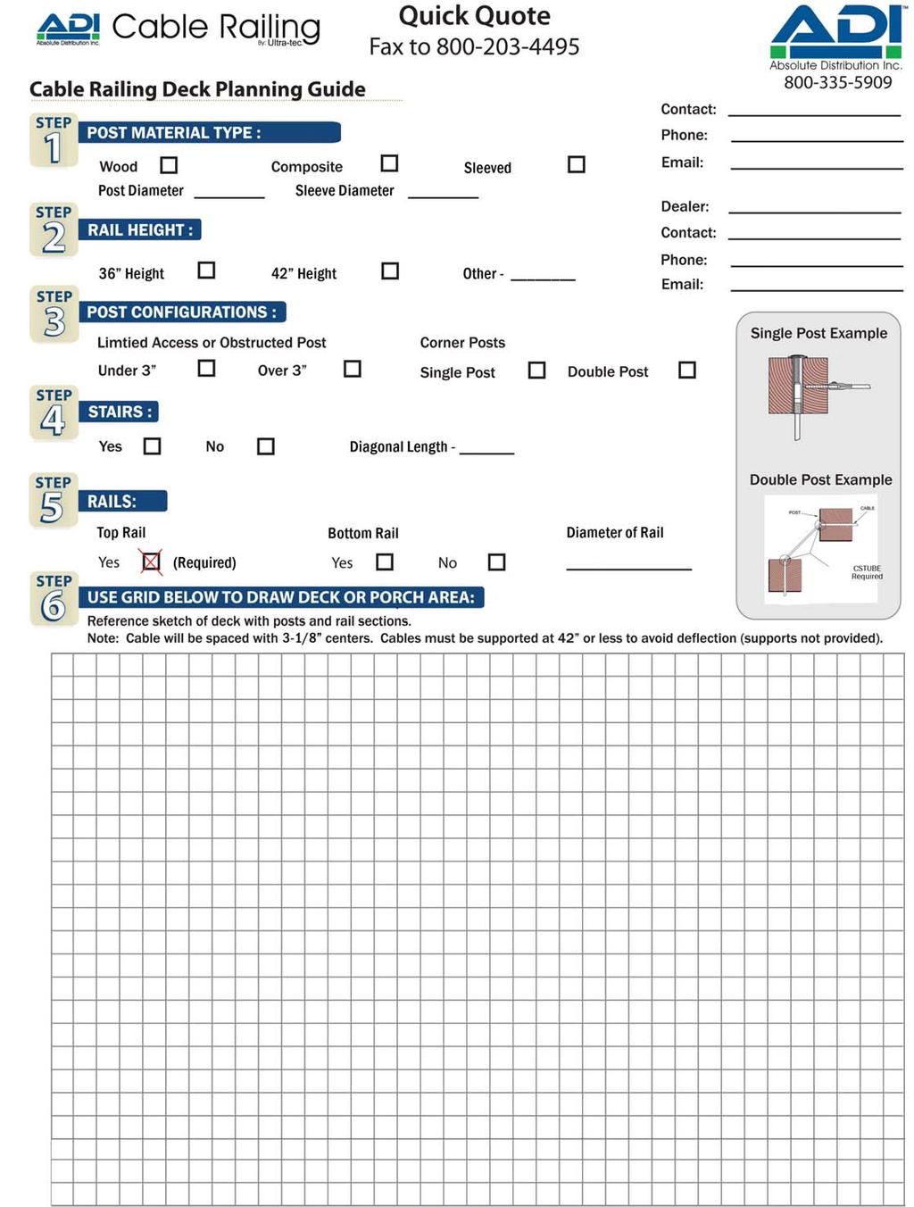
2 Framework for Cable Railing End Post Construction Since hundreds of pounds of tension are being applied to end posts using cable railing, those posts must be substantial enough to handle that tension. For wood posts a minimum 4x4 post is required to keep the post from bending when the cables are tensioned. You will need a top rail, and we recommend that it be reinforced with a support such as a 2x4 on end under the top rail (see illustration at right). End posts must be securely ed to the deck to prevent the post from coming loose when the cables are tensioned. A bottom rail helps distribute the force away from the bottom of the post, but is not required. Of course, secure ing of the intermediate posts to the deck is just as important as with end posts. Intermediate Posts / Cable Braces To keep the cable from spreading beyond IBC code requirements, we recommend that the cable be supported in some manner no more than every 42 along its run. Intermediate posts, through which the cable is strung, act as supports for the cable. To avoid having to use more intermediate posts than is structurally necessary, an aluminum cable brace with holes for the cables to pass through can be used to support the cables (see illustrations). A typical cable brace is 3/4 x 3/4 square aluminum tube. Cable Spacing We recommend that you space the cables with no more than a 3 clear span between the cables (see illustrations). For example, if you are using 1/8 diameter cable, you would drill your holes on center no more than 3-1/8 apart. Cable Diameter Sizes The most common cable sizes are 1/8 diameter cable and 3/16 diameter cable. 1/8 is used mostly for residential railing systems and maximizes the view that cable is known for. 3/16 Cable is used for commercial rail jobs that require a more heavy duty cable rail application. Code Compliance Guidelines 4 Sphere Rule: With 3 spacing, lbs of tension and a cable support every 42 or less the The Ladder Effect : In 2001 IRC code cycle Change was noted in 2001 IRC supplement and has not appeared in the 2003, 2006, 2009, or 2012 publications. Ladder effect has never been part of the IBC. However, you should always check appear in local codes. 2
 Push-Lock with Threaded Eye and Lag Eye to Adjust-a-Body with Threaded Eye and Lag Eye.")
 300-C Series ( to ) Adjust-a-Body with Extended Length Hanger Bolt to Push-Lock with Extended Length Lag.")

3 For level runs: 224 Series ( to ) 2-3/8 Invisiware Receiver to Pull-Lock. 300 Series ( to ) Adjust-a-Body with Hanger Bolt to Push-Lock Lag. 601 Series ( to ) 3½ Invisiware Receiver to Push-Lock Lag. Kit Assemblies for Wood Posts For stairs, pitched runs: 500-W Series ( to ) Push-Lock with Threaded Eye and Lag Eye to Adjust-a-Body with Threaded Eye and Lag Eye. Kit Assemblies For Composite Sleeved Wood Posts For level runs using wood posts with composite sleeves. (Outside diameter GREATER than 4-1/2 ) 300-C Series ( to ) Adjust-a-Body with Extended Length Hanger Bolt to Push-Lock with Extended Length Lag. For stairs using wood posts with composite sleeves: (Outside diameter GREATER than 4-1/2 ) 500-C Series ( to ) Adjust-a-Body with Threaded Eye and Extended Length Lag Eye to Push-Lock with Threaded Eye and Extended Length Lag Eye. Recommendations for wood railings: Outside attachments can only be used if your end posts are not obstructed on the back side: Series 200; or Series 601 or if only one end is obstructed. If you are unable to access the back side of your end post, then you will need to use a series with an attachment: Series 300 or 500 if both ends are obstructed; Series 601 if only one end is obstructed. If you are installing a railing with a pitch, you will need a series that can be run on an angle: 500 Series. 3

4 Single Post Options Cable Options for Post Against a Structure 1. Through Post Fittings Fittings that go through the post need at least 3-1/2 of space between the post and the structure to allow for cable to be installed and/or tensioned without issue. 2. Lag Style Fittings is set less than 3-1/2 from a structure. This of the post and does not require access to the back side of the post. Space 3-1/2 Minimum Space Less Than 3-1/2 House INVISIWARE RECEIVER House LAG FITTING Cable Options for Intermediate Post 1. Shared Line Post If ever, you need to start and stop cable on be used. This scenario may occur for very long runs that need to be broken up into multiple sections of cable. 2. Cable Bending at a Single Post When cable needs to go out of the post at an angle, this can be achieved by a couple methods. 1. Starting and stopping cable at a single post. (Commonly used for Stairs or Sleeved Posts) LAG EYE ADJUST-A-BODY WITH HANGER BOLT PUSH-LOCK LAG PUSH-LOCK with THREADED EYE PUSH-LOCK LAG 2. Running continuous cable and bending cable at post with post protector tube. (not to exceed 45 degrees) 4
 Fittings are designed so the lag post on the same plane. 2.")
5 A Closer Look at Corner Posts Where Two Cable Runs Intersect While you can offset cables on intersecting runs to their cables to exist on the same plane, to give the impression that cables are continuous. Single Corner Post Options Below are some examples of how your kit components work together. 1. Same Plane (Option 1) Fittings are designed so the lag post on the same plane. 2. Same Plane (Option 2) a single corner post on the same plane without colliding in the post. 3. Offset Fittings Fittings that go through the post and share a single corner post, must be offset so they do not collide in the post. INVISIWARE RECEIVER INVISIWARE RECEIVER ADJUST-A-BODY WITH HANGER BOLT INVISIWARE RECEIVER PUSH-LOCK LAG PUSH-LOCK LAG Double Corner Post Options 1. Start and Stop Cable Runs corners with two post. Cables are able to stay on same plane. INVISIWARE RECEIVER 2. Continuous Cable Run Through a Corner When taking cable railing through a corner, do not bend the cable past 45 at any time. If turning 90, a 2-step turn using a double corner post through multiple corners totaling more than 90, you will want to use a kit with tensioners at both ends. (See Pages 18-19) Corners require two posts because the cable itself, being rigid, will not cooperate in bending cleanly through a single post. When you go through a corner post, you will need to prevent the cable from slicing into the wood as it exits the post on an angle by using a Post Protector Tube. INVISIWARE RECEIVER 5


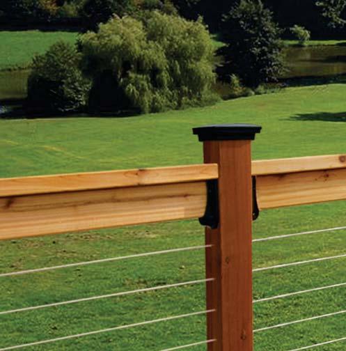
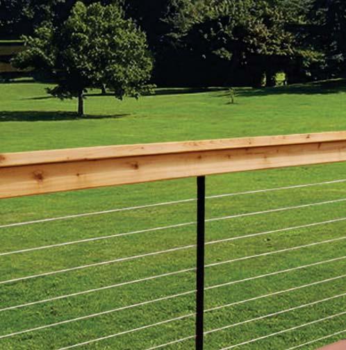
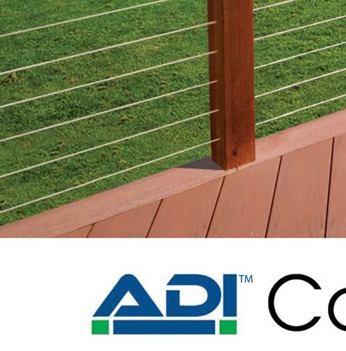
6 Decks come in all shapes and sizes, but there are only a few types of cable runs that go on those decks: -of-post to -of-post, -of-post to -of-post, and -of-post to -of-post. The following illustrations represent several ways you can run cable on your deck. Every run will require a Depending on the length of the run, the tensioning device in the kit, and whether you plan to bend the cable through a corner, you will either be able to use a Your Deck Type non-tensioning Push-Lock or Pull-Lock on the other end or you will need to use a Push-Lock tensioner on the other end. The VIP Run You will see that Run #1 on each drawing is the view run the one that is most important, most visible of all your runs. It s the one on which you want to have the least interference with the view, so you always start with that run and build around it. Stained Cedar Rail with Cable Wood Rail with Cable Azek Composite Sleeve w/ Cable Redwood Rail with Cable 6


7 Wood Posts - Outside-of-Post to Outside-of-Post Mount Straight Cable Runs and Cable Runs Through One Corner Deck 1 has dedicated end posts for each run, and the posts are situated such that the back side of the posts are all accessible, meaning you can use an -ofpost to -of-post is both the most economical solution and where the Deck 2 illustrates how the 224 series can also be used to go around a single corner up to 90. Applicable kit is the 224 Series. The tensioning device is a 2-3/8 long Invisiware Receiver, which installs through the post on one end. A Pull-Lock installed through the other end. Run #2 3½ min. Post Protector Tubes in W ood Posts House 3½ min. 3½ min. Deck 1 Run #1 Series 224 House Deck 2 Run #3 Series 224 For Post Protector Tubes, see Accessories and Equipment page. Tools needed for 224 Series: 5/32 drill bit if 1/8 cable, 7/32 if 3/16 29/64 drill bit for Receiver and Pull-Lock installation 3/16 Hex wrench for tensioning Receiver Cable cutting tool If using Post Protector Tubes, 1/4 drill bit See ADI Cable Rail Basic Install Kit - ADICRKIT Series 224 Kits Cable 1/8 cable 3/16 cable Lengt h PART NO. PART NO

8 Wood Posts - Inside-of-Post to Outside-of-Post Mount Straight Cable Runs and Cable Runs Through One Corner Deck 1 has dedicated end posts, but the posts next to the house are too close to access the back side of the posts. Run #1 is to, so it will take a Series 224 kit. However, for Runs #2 and #3, you will attach to the of the posts next to the house and run through the post at the other end. Deck 2 illustrates how the 601 series can also be used to go around a single corner up to 90. Run #2 House Deck 1 Series 601 Run #3 Applicable kit is the 601 Series The tensioning device is a 3½ long Invisiware Receiver, which installs through the wood post on one end. A Push- Lock Lag is lagged into the other end. Run #1 Series 224 House Deck 2 Post Protector Tubes in Wood Posts Tools needed for 601 Series: 5/32 drill bit if 1/8 cable, 7/32 if 3/16 29/64 drill bit for Receiver installation 3/16 Hex wrench for tensioning Receiver 9/32 drill bit for Push-Lock Lag installation 7/16 wrench for tightening Push-Lock Lag Cable cutting tool If using Post Protector Tubes, 1/4 drill bit See ADI Cable Rail Basic Install Kit - ADICRKIT Series 601 For Post Protector Tubes, see Accessories and Equipment page. Series 601 Kits Cable 1/8 cable 3/16 cable Length PART NO. PART NO
9 Wood Posts - Inside-of-Post to Inside-of-Post Mount Straight Cable Runs and Cable Runs Through One Corner Deck 1 has only one end post at the corners. The posts next to the house butt right up to it so the back sides of those posts are not accessible. Run #1 is still to, so it will take a Series 224 kit. Runs #2 and #3 connect to the of the corner post going back toward the house to keep the cables on the same plane. They also connect to the of the posts next to the house as well. Run #2 House Deck 1 Series 300 Run #3 Deck 2 illustrates how the 300 series can also be used to go around a single corner up to 90. Run #1 Series 224 Applicable kit is the 300 Series. The tensioning device is an Adjust-a-Body with Hanger Bolt, which lags into the wood post on one end. A Push-Lock Lag is lagged into the other end. Post Protector Tubes in W ood Posts House Deck 2 Tools needed for 300 Series: 5/32 drill bit if 1/8 cable, 7/32 if 3/16 cable 3/16 Hex wrench for tensioning Receiver 1/4 drill bit for Adjust-a-Body with Hanger Bolt installation and installing Post Protector Tubes 1/4 wrench for turning Hanger Bolt 9/32 drill bit for Push-Lock Lag installation 7/16 wrench for tensioning Adjust-a-Body and tightening Push-Lock Lag 3/8 wrench for Push-Lock Stud Cable cutting tool See ADI Cable Rail Basic Install Kit - ADICRKIT Series 300 For Post Protector Tubes, see Accessories and Equipment page. Series 300 Kits Cable 1/8 cable 3/16 cable Length PART NO. PART NO

10 I:I Wood Posts on Stairs - Inside-of-Post to Inside-of-Post Mount Cable Runs on a Pitch Top posts are often corner posts, which may require the stair run to connect to the of the post. The top and bottom of the cable run would be connected perpendicular to those posts, and only the intermediate posts would be drilled on the angle for the cable to run through. The 500-W Series can also be used to go up a stair and across a landing by inserting post protector tubes The tube will prevent the cable from carving a groove into your post where it exits at an angle. Applicable kit for wood posts is the 500-W Series. The tensioning device is an Adjust-a-Body with Threaded Eye, which attaches via ing screw to the lag eye. A Push-Lock with Threaded Eye attaches the same way to the other end. Adjust-A-Body with Threaded Eye 1/8 and 3/16 1x19 stainless steel cable Post Protector Tube Pre-attached swaging ferrule Push-Lock Threaded Eye Lag Eye Lag Eye SC-6 Screw SC-6 Screw 500-W Series 10 Series 500-W Kits for Wood Posts Cable 1/8 cable 3/16 cable Length PART NO. PART NO W W W W W W W W W W W W W W W W Tools needed for 500-W Series: 5/32 drill bit if 1/8 cable, 7/32 if 3/16 9/32 drill bit for Lag Eye installation 7/16 wrench for tensioning Adjust-a-Body 5/32 Hex wrench to tighten ing screws Cable cutting tool If using Post Protector Tubes, 1/4 drill bit See ADI Cable Rail Basic Install Kit - ADICRKIT
11 O:O Wood Posts on Stairs - Outside-of-Post to Outside-of-Post Cable Runs on a Pitch An alternative to ing to the of the stair posts is to go through both top and bottom end posts. The holes in the end posts, and any intermediate posts, must be drilled on the angle of the stairs. The 224 Series can also be used to go up a stair and across a landing by inserting post protector tubes The tube will prevent the cable from carving a groove into your post where it exits at an angle. Applicable kit is the 224 Series. Requires beveled combo separately from the kit. The tensioning device is a 2-3/8 long Invisiware Receiver, which installs through the wood post on one end. A Pull-Lock Post Protector Tube Series 224 Kits Cable 1/8 cable 3/16 cable Lengt h PART NO. PART NO Order two BW356 (beveled washer/flat washer combo) per kit, one combo if one end post is on a landing. See Tools and Essentials section. Tools needed for 224 Series on stairs: 5/32 drill bit if 1/8 cable, 7/32 if 3/16 29/64 drill bit for Receiver and Pull-Lock installation 3/16 Hex wrench for tensioning Receiver Cable cutting tool If using Post Protector Tubes, 1/4 drill bit See ADI Cable Rail Basic Install Kit - ADICRKIT 11


12 Wood Posts with Composite or Aluminum Sleeves Inside-of-Post to Inside-of-Post Mount Straight Cable Runs Deck 1 has wood posts with composite sleeves. For sleeved posts, the recommended look. Each run must be start and stop at corner posts. All three runs use the same kit. House Deck 1 Applicable kits are the 300 and 300-C Series: If the diameter of the composite sleeve is 4½ or LESS, use the 300 Series. The tensioning device is an Adjust-a-Body with Hanger Bolt, which lags into the wood post on one end. A Push-Lock Lag is lagged into the other end. If the diameter of the composite sleeve is GREATER than 4½, use the 300-C Series. with extended length hanger bolt and lag respectively. s Series 300-C 4-1/2 or Greater s ADJUST-A-BODY with EXTENDED HANGER BOLT Gap Between Sleeve and Post PUSH-LOCK EXTENDED LENGTH LAG Sample: Aluminum Sleeves over 4x4 wood post & aluminum top rail 12 Cable 1/8 cable 3/16 cable Length PART NO. PART NO Series 300-C Kits C C C C C C C C C C C C C C C C6

13 I:I Wood Posts with Composite or Aluminum Sleeves For Stairs - Inside-of-Post to Inside-of-Post Mount Cable Runs on a Pitch Top posts are often corner posts, which may require the stair run to connect to the of the post. The top and bottom of the cable run would be connected perpendicular to those posts, and only the intermediate posts would be drilled on the angle for the cable to run through. Applicable kits are 500-W or 500-C Series: If the diameter of composite sleeve is 4½ or LESS, use the 500-W Series. The tensioning device is an Adjust-a-Body with Threaded Eye, which attaches via ing screw to the lag eye. A Push-Lock with Threaded Eye attaches the same way to the other end. If the diameter of composite sleeve is GREATER than 4½, use the 500-C Series. The tensioning device is an Adjust-a-Body with Threaded Eye, which attaches via ing screw to the extended length lag eye. A Push-Lock with Threaded Eye attaches the same way to the other end. Series 500-C Kits for Wood Posts with Composite Sleeves Cable 1/8 cable 3/16 cable Length PART NO. PART NO C C C C C C C C C C C C C C C C Tools needed for 500-C Series: 5/32 drill bit if 1/8 cable, 7/32 if 3/16 9/32 drill bit for Lag Eye installation 7/16 wrench for tensioning Adjust-a-Body 5/32 Hex wrench to tighten ing screws Cable cutting tool See ADI Cable Rail Basic Install Kit - ADICRKIT Tools needed for 300-C Series (page 12): 5/32 drill bit if 1/8 cable, 7/32 if 3/16 cable 3/16 Hex wrench for tensioning Receiver 1/4 drill bit for Adjust-a-Body with Hanger Bolt installation and installing Post Protector Tubes 1/4 wrench for turning Hanger Bolt 9/32 drill bit for Push-Lock Lag installation 7/16 wrench for tensioning Adjust-a-Body and tightening Push-Lock Lag 3/8 wrench for Push-Lock Stud Cable cutting tool See ADI Cable Rail Basic Install Kit - ADICRKIT 13
 7½ long threaded stud to Pull-Lock with beveled washers (BW-.250-32 for stud, BW32-6W for Pull-Lock ).")

14 Fitting combinations for wood posts For level runs: 100 Series ( to ) 7½ long threaded stud to Pull-Lock. For stairs, pitched runs: 100 Series ( to ) 7½ long threaded stud to Pull-Lock with beveled washers (BW for stud, BW32-6W for Pull-Lock ). Budget Kits for 1/8" Cable *Special Order - Allow Two Weeks Lead Time* 100 Series 100 Series with beveled washers Important Notes for Budget Kits: posts are not obstructed on the back side. itself, being rigid, will not cooperate in bending cleanly through a single post. than 45 at any post), you will need to prevent the cable from slicing into the wood as it exits the post on an angle by using a Post Protector Tube (see Tools and Essentials section). need beveled washers for both ends. Wood Posts - Outside-of-Post to Outside-of-Post Mount 14 the only scenario in which the economical threaded stud kits may be used. The threaded stud kits are even more economical than the 200 series, but the hide-in-the-post solution. Two jam nuts and some metal thread (all covered by an end cap) will extend beyond the back of the post on one end. A Pull-Lock (Takes longer to install than 224 Series cable kit and For wood posts, the applicable kit is the 100 Series. The tensioning device is a 7½ long threaded stud which installs on the back side of one end post, as shown in Deck 1. Pre-attached 7½ threaded stud Nut cap 1/8 1x19 stainless steel cable Stainless Steel washers Stainless Steel jam nuts 100 Series Pull-Lock Fitting with cap House 3½ min. 3½ min. Deck 1 Series 100 Series 100 Kits Cable Length PART NO Post Protector Tubes in W ood Posts For Post Protector Tubes, see Accessories and Equipment page.


15 Cable Braces Pre-Drilled Aluminum Cable Brace 3/4 x 3/4 tube, 42 long for cutting down to any size rail height. Holes pre-drilled at 3-1/8 on center, 13 holes total. For use between structural posts to brace plugs to attach to top and bottom rail or deck. Cedar Rail with Cable Cable brace must be used every 42 to The cable brace is not a structural member of the rail. Anodized: Order CB-42-AN-AL-13-P Black: Order CB-42-BL-AL-13-P Undrilled Aluminum Cable Brace for Stairs 3/4 x 3/4 tube, 42 long for cutting down to any size rail height. Comes undrilled to match cable array. Anodized: Order CB-42-AN-AL-P Black: Order CB-42-BL-AL-P Pre-Drilled Aluminum Cable Brace for Stairs 3/4 x 3/4 tube, 50 long for cutting down to any size rail height. Comes pre-drilled with 12 slotted and offset holes to match cable array. Anodized: Order CB-50-AN-12-P Black: Order CB-50-BL-12-P 15


16 16 Tools and Essentials Stainless Steel Post Protector Tube The post protector tube is inserted into a wood post where the cable enters/exits the post at an angle to keep cable from biting into the wood. Order CS-TUBE6 For 1/8 and 3/16 dia. cable Cable Release Releases cable from Push-Lock and Pull-Lock before cables are tensioned. For 1/8 cable only. Order PL-KEY Ultra-tec Lag Eye For attaching an Adjust-A- Body with Threaded Eye or Push-Lock Threaded Eye to a wood Post. Order: LE6 or LE-6L for Extended Length Cable Gripping Pliers cable to avoid winding during installation. Order: PLIERS Cable Cutter For burr-free cutting of cable. For light-duty use to cut 1/8 diameter cable, order C-7HIT ADI Cable Step Drill For wood post to make and 3/16 hole for cable using a single drill bit. order CSD316 ADI Cable Railing Basic Install Kit Kit comes with necessary drill bits, tools, and a cut off wheel to properly install cable railing. Order: ADICRKIT Light Duty Hanger Bolt Driver with driving hanger bolts fast and easy. Order: HB6N/R Heavy Duty Hanger Bolt Driver 1 pc. self-gripping design intended for multiple installations. Order HB6DRIVER/R Beveled Washers use on stairways or slopes where you need to drill your end post holes at an angle. Order two of BW356 Beveled Washer/Flat Washer per cable run Cable Tension Gauges Check the tension on your cables with these easy-to-use gauges. Order PT-CR for cable diameter of 1/8, 3/16 Stainless Steel Cleaner and Protectant Dissolve minor corrosion, then leave a protective coating that lasts for months. Includes an 8-oz. spray-on rust and stain remover and a 4-oz. bottle of protectant. Order EZ Clean 1/2 drive 1/2 drive
17 Reviewing the Cable Basics - The bottom rail is optional providing the posts are securely anchored. - The cable brace is not a structural member so you can use a variety of cable - If no bottom rail is being used. by making a 45 degree turn through the posts. - Single tensioner (most common) cable kits allow cable to pass through one corner. - Double tensioner cable kits allow cable to pass through two corners. 17
 Adjust-a-Body with Hanger Bolt to Push-Lock Turnbuckle with Hanger Bolt.")


18 Special Applications For level runs: 272 Series ( to ) 3½ Invisiware Receiver to 1½ Receiver with Push-Lock Stud. 672 Series ( to ) Adjust-a-Body with Hanger Bolt to 1½ Receiver with Push-Lock Stud. 371 Series ( to ) Adjust-a-Body with Hanger Bolt to Push-Lock Turnbuckle with Hanger Bolt. Cable Kits with Double Tensioners Special Applications Cable Kits Using Two Tensioning Fittings When going around two corners, or making multiple turns that equate to more than 90 Degrees, it is required to tension the cable from both ends. If the cable makes more than one 90 degree turn the friction and the angle will keep the cables from being able to be tensioned from a single tensioning end. These cable kits are not recommended for common installations, but provide a solutions for unique installations. Wood Posts - Outside-of-Post to Outside-of-Post Mount Cable Runs through Two Corners When going around two corners, it s necessary to tension the cable from both ends as shown in Deck 1. Applicable kit is the 272 Series. The tensioning devices are a 3½ long Invisiware Receiver, which installs through the post on one end, and a Push-Lock Stud on the other end, which is threaded into a 1½ long Receiver. 18 Series 272 Kits Cable 1/8 cable 3/16 cable Length PART NO. PART NO ½ min. Post Protector Tubes in Wood Posts House Deck 1 Series 272 3½ min. For Post Protector Tubes, see Accessories and Equipment page. Post Protector Tubes in Wood Posts Tools needed for 272 Series: 5/32 drill bit if 1/8 cable, 7/32 if 3/16 29/64 drill bit for Receiver and Pull-Lock installation 3/16 Hex wrench for tensioning Receiver Cable cutting tool If using Post Protector Tubes, 1/4 drill bit If 272 Series, 3/8 wrench for Push-Lock Stud


19 Special Applications Wood Posts - Inside-of-Post to Outside-of-Post Mount Cable Runs through Two Corners When going around two corners, it s necessary to tension the cable from both ends as shown in Deck 2. Applicable kit is the 672 series. The tensioning devices are an Adjust-a-Body with Hanger Bolt which lags into the wood post on one end, and a 1-1/2 long Receiver with Push-Lock Stud on the other end. Cable Runs through Two Corners When going around two corners, it s necessary to tension the cable from both ends as shown in Deck 3. Applicable kit is the 371 Series. The tensioning devices are an Adjust-a-Body with Hanger Bolt, which lags into the wood post on one end, and Push-Lock Turnbuckle with Hanger Bolt on the other end. Cable 1/8 cable 3/16 cable Length PART NO. PART NO Cable 1/8 cable 3/16 cable Length PART NO. PART NO Series 672 Kits Series 371 Kits ½ min. Post Protector Tubes in W ood Posts Post Protector Tubes in W ood Posts House Deck 2 Deck 4 Series 672 Tools needed for 672 Series: 5/32 drill bit if 1/8 cable, 7/32 if 3/16 29/64 drill bit for Receiver installation 3/16 Hex wrench for tensioning Receiver 9/32 drill bit for Push-Lock Lag installation 1/4 drill bit for Adjust-a-Body installation 1/4 wrench for turning Hanger Bolt 7/16 wrench to tension Adjust-a-Body 3/8 wrench for Push-Lock Stud Cable cutting tool Wood Posts - Inside-of-Post to Inside-of-Post Mount House Deck 3 Series 371 Post Protector Tubes in W ood Posts For Post Protector Tubes, see Accessories and Equipment page. Post Protector Tubes in W ood Posts For Post Protector Tubes, see Accessories and Equipment page. Tools needed for 371 Series: 5/32 drill bit if 1/8 cable, 7/32 if 3/16 cable 3/16 Hex wrench for tensioning Receiver 1/4 drill bit for Push-Lock Turnbuckle 1/4 wrench for turning Hanger Bolt 3/8 wrench for Push-Lock Stud Cable cutting tool 19 Special Applications

20 railing systems Aluminum Railing and Cable System AS&D Aluminum Rail and Cable with Series 200 Aluminum Woodgrain Top Rail 20 AS&D Product Features (Bronze and White are Special Order)


21 Framework for AS&D Aluminum Rail and Cable System Double Posts for Corners Over-the-Post Top Rail 3-3/16 Cable Spacing 48 Maximum Between Posts Pre-Drilled End Post Pre-Drilled Intermediate Post Rail Overview and stainless steel cable allows for railings to be lightweight, while still retaining exceptional durability. Railings will not rust, rot, swell, warp, twist, split, or crack and require little to no user maintenance. Rail Guidelines To keep the cable from spreading beyond IBC code requirements, AS&D rail requires that the cable be supported with a post every 48 along its run. Cables are to be spaced at 3-3/16 spacing on center. Two posts must be used to create a 90 degree corner and/or a 45 degree turn. Cable can start and stop at the corner or it can pass through the corner. Top rail is required for all railing installations. Posts AS&D posts for level railings are all pre-drilled and ready for cable installation. Posts for stairs come undrilled to for surface or fascia and available for 36 and/or 42 rail heights. Top Rails There are 3 styles of top rail that AS&D railing utilizes: Series 200 addition of a secondary handrail system. Series 100 Series 400 Available Colors: *Colors shown are approximate representation* Anodized (Silver) Black Bronze (Non-Stock) White (Non-Stock) 21

22 For level runs: 224 Series ( to ) 2-3/8 Invisiware Receiver to Pull-Lock. For stairs, pitched runs: 224 Series ( to ) 2-3/8 Invisiware Receiver to Pull-Lock. Kit Assemblies for AS&D Posts End Post and Corner Post Guidelines 1. End Post against a Structure Fittings that go through the post need at least 3-1/2 of space between the post and the structure to allow for cable to be installed and/or tensioned without issue. House Space 3-1/2 Minimum INVISIWARE RECEIVER 1. Start and Stop Cable Runs corners with two post. Cables are able to stay on same plane. 2. Continuous Cable Run Through a Single Corner When taking cable railing through a corner, do not bend the cable past 45 at any time. When turning 90, a 2-step illustrated. AS&D railing requires two posts for corners. 22


23 AS&D Railing System Overview Posts posts for cable center or less finishes - Anodized (Silver), Black, Bronze and White. Surface Mount Post Fascia Mount Post Top Rail Options 3-1/2 x 1-7/8 x 8 Contemporary aluminum top rail. Join multiple rails together with splices to achieve any length required. Field trimmable with carbide blade. Includes bottom End plate sold separately. 2 x 1-5/8 x 8 Aluminum top rail. handrail when used over the post. Field trimmable with carbide blade. Includes End plate sold separately. Series 400 aluminum rail cap for attaching wood/composite top rail. Field trimmable with carbide blade. 23


24 AS&D Post - Outside-of-Post to Outside-of-Post Mount Straight Cable Runs and Cable Runs Through One Corner Deck 1 has dedicated end posts for each run, and the posts are situated such that the back side of the posts are all accessible, meaning you can use an -ofpost to -of-post 3½ min. House Deck 1 Deck 1 3½ min. When taking cable railing through a corner, there are two options: Option 1: Starting and Stopping cable kits at each corner as shown in Deck 1. Option 2: Run cables continuously through a single corner as shown in Deck 2. Run #2 Run #1 Series 224 Run #3 For 2-3/8 posts, applicable kit is the 224 Series. The tensioning device is 2-3/8 long Receiver, which installs through the aluminum post on one end. A Pull-Lock through the other end. Deck 2 Pre-attached swaging stud Invisiware Receiver 1/8 and 3/16 1x19 stainless steel cable Delrin washers for use with metal posts 224 Series Pull-Lock Fitting with cap Series 224 Kits Cable 1/8 cable 3/16 cable Lengt h PART NO. PART NO Tools needed for 224 Series: 3/16 Hex wrench for tensioning Receiver Cable cutting tool and Cable gripping pliers


25 AS&D Posts for Stairs - Outside-of-Post to Outside-of-Post Cable Runs on a Pitch Due to many variables in stair applications, stair posts are undrilled to allow maximum flexibility and custom drill hole placement for cables. All stair posts require the addition of a surface base plate or fascia bracket for ing. The holes in the end posts are to be drilled straight through with a 29/64 bit and any intermediate posts must be drilled with offset holes to accommodate to the angle of the stairs using a 3/16 bit. Deck 1 Stair Options Deck 1 - Stopping and Starting Cable. Cable Runs are broken into two sections, one for level and the other for stair. This allows for the Series 100 top rail to be used for the stairs, which doubles as a graspable handrail. Deck 2 - Continuous cable from level to stair. Cable runs through a single post at the top of the stairs without stopping. This can be achieved with either a Series 200 or Series 400 top rail. However, these top rails do not qualify as graspable rail and a secondary handrail may be required. Deck 2 For 2-3/8 posts, applicable kit is the 224 Series. The tensioning device is 2-3/8 long Receiver, which installs through the aluminum post on one end. A Pull-Lock through the other end. AS&D Aluminum Rail and Cable - Series 100 Top Rail Series 224 Kits Cable 1/8 cable 3/16 cable Lengt h PART NO. PART NO Tools needed for 224 Series on stairs: 5/32 drill bit if 1/8 cable, 7/32 if 3/16 3/16 Hex wrench for tensioning Receiver 29/64 drill bit for Receiver and Pull-Lock installation Cable cutting tool 25


26 Aluminum Sleeve or Composite Sleeve Applications Inside-of-Post to -of-post Mount Straight Cable Runs Deck 1 has wood posts with aluminum sleeves. For sleeved posts, the recommended approach run must be start and stop at corner posts. House Deck 1 Applicable kit are the 300 Series: If diameter of the sleeve is 4½ or LESS The tensioning device is an Adjust-a-Body with Hanger Bolt, which lags into the wood post on one end. A Push-Lock Lag is lagged into the other end. s s Applicable kits are the 300-C Series: If the diameter is GREATER than 4½ with extended length hanger bolt and lag respectively. Series 300-C Dekpro Prestige Textured Aluminum over 4x4 wood post. Sample: Solutions Aluminum over 4x4 wood post. 26 *See page 16 for list of tools needed for installing cable


27 Aluminum Sleeve or Composite Sleeve Applications for Stairs - Inside-of-Post to -of-post Mount Cable Runs on a Pitch Top posts are often corner posts, which may require the stair run to connect to the of the post. The top and bottom of the cable run would be connected perpendicular to those posts, and only the intermediate posts would be drilled on the angle for the cable to run through. Applicable kits are the 500-W Series: If diameter of the sleeve is 4½ or LESS The tensioning device is an Adjust-a-Body with Threaded Eye, which attaches via ing screw to the lag eye. A Push-Lock with Threaded Eye attaches the same way to the other end. Applicable kits are the 500-C Series: If diameter of the sleeve is GREATER than 4½ The tensioning device is an Adjust-a-Body with Threaded Eye, which attaches via ing screw to the extended length lag eye. A Push-Lock with Threaded Eye attaches the same way to the other end. Adjust-A-Body with Threaded Eye 1/8 and 3/16 1x19 stainless steel cable Shared Stair Post (Level to Stair) end the level run. Series 500W adjustable cable the stairs. This way the cable enters and leaves the post at the same plane for a consistent look. Pre-attached swaging ferrule Lag Eye Lag Eye SC-6 Screw 500-W Series Push-Lock Threaded Eye SC-6 Screw (500W Series) Wood Post w/ Aluminum Sleeve (300 Series) Tools needed for 500-W Series: 5/32 drill bit if 1/8 cable, 7/32 if 3/16 9/32 drill bit for Lag Eye installation 7/16 wrench for tensioning Adjust-a-Body 5/32 Hex wrench to tighten ing screws Cable cutting tool If using Post Protector Tubes, 1/4 drill bit See ADI Cable Rail Basic Install Kit - ADICRKIT *Concept of Installation is the same for both Aluminum Sleeved Posts and Composite Sleeved Posts* 27
 Invisiware Receiver to Pull-Lock.")


 years from the date of receipt to be free from defects due to defective materials and")
28 Providing Your Own Metal Rail System? ADI Cable Railing by Ultra-tec has options! For level runs: 200 Series* ( to ) Invisiware Receiver to Pull-Lock. * 212 series are for use with 1½ metal posts; * 232 are for use with 2 metal posts. * 224 are for use with 2-3/8 metal posts. * 252 are for use with 3 metal posts. 401 Series ( to ) Adjust-a-Body with Threaded Bolt to Push-Lock with Threaded Bolt. For stairs, pitched runs: Push-Lock with Threaded Eye to Adjust-a-Body with Threaded Eye. Threaded tabs on both ends. Please contact ADI for cable kits to use with your own metal post Custom Metal Rail w/ Cable 28 Warranty: Stainless steel hardware and cable are covered by a limited warranty for a period of ten (10) years from the date of receipt to be free from defects due to defective materials and workmanship. For complete warranty details, please visit Ph: Web: w.absolutedist.com Fax: sales@absolutedist.com


29 Idea Gallery Cedar Rail w/ Cable Redwood Rail w/ Cable using Intermediate Cable Braces Composite Sleeves w/ Cable AS&D Surface Mount Aluminum Rail AS&D Fascia Mount Aluminum Rail Custom Metal Post w/ Cable
30 Get A Project Quote From Your Dealer Send ADI a Drawing and We ll Do the Take-Off Quotes@absolutedist.com or Please Include The Following: railing lengths, end and corner post locations, stairs and any angles/turns your railing takes. Please include the following: hat size post? What material (wood/composite sleeve)? If composite sleeve, what is the diameter when installed? What is the height of the railing? Are you using a bottom rail? Are you using single posts at corners or a double Do you have 3-1/2 of space behind end posts to allow for installation of Receivers and Pull-Locks? What diameter cable are you using? (1/8 typically for residential or 3/16 for commercial)? 3/16 cable - Allow 2-3 week lead time. Warranty Information Stainless steel hardware and cable are covered by a limited warranty for a period of ten (10) years from the date of receipt to be free from defects due to defective materials and workmanship. This warranty does not cover materials which have been abused, neglected or used in any manner other than for pedestrian railings nor for any damage, failure of corrosion resulting from environmental conditions, improper installation, vandalism, insurrection, war or acts of nature. The company s obligations are limited to the replacement or refund of the net purchase price of the materials found to be defective and does not cover any other related cost for the disassembly of the defective materials nor the installation costs of the replacement material. In making a claim the material shall be delivered to ADI with a written notice of the defect and evidence that the condition or product failure is covered by this warranty. For complete warranty details, please visit 30 Ph: Web: w.absolutedist.com Fax: sales@absolutedist.com
31
32 Available Thru:
March 1, Fax:
 March 1, 2017 U.S.A. Manufacturer The Cable Connection 52 Heppner Drive Carson City, Nevada 89706 800.851.2961 775.885.1443 Fax: 775.885.2734 E-mail: info@ultra-tec.com www.ultra-tec.com Framework You
Cable Railing Kit Application Guide
 Cable Railing Kit Application Guide January 2019 Nationwide Industries 10333 Windhorst Rd. Tampa, FL 33619 813.988.2628 Fax: 813.988.3465 Photo courtesy of FabWorx Framework You Will Need for Cable Railing
Open Up Your View With CABLE SYSTEMS
 Open Up Your View With CABLE SYSTEMS PRESENTED BY CROWN HERITAGE Our Cable Multiple options to accomodate any deck or stair design Marine Grade 316 stainless steel Swaging is the term used for attaching
ADI CABLE RAILING FOR METAL. AS&D TM Aluminum Railing. Solutions TM Aluminum Railing
 TM ADI CABLE RAILING FOR METAL AS&D TM Aluminum Railing pg 120-131 Solutions TM Aluminum Railing pg 132-133 119 AS&D Railing System Overview For the discriminating homeowner, a contemporary, esthetically
Face Mount to Through-the-Post Mount
 Face Mount to Through-the- Mount Cable Runs through Two Corners When going around two corners, it s necessary to tension the cable from both ends as shown in Deck 4. Use the 672 series The tensioning devices
DekPro InvisiCable. Cable Railing for Wood Systems
 DekPro InvisiCable Cable Railing for Wood Systems A simple, affordable cable railing option for the value conscious consumer that wants the look of cable but at a lower cost. Proudly made in the USA of
Architectural Cable Railing Products
 Architectural Cable Railing Products August 1, 2017 ISO Certified U.S.A. Manufacturer www.ultra-tec.com TABLE OF CONTENTS ULTRA-TEC RAILING PRODUCTS Cable Type and Size... 3 Options for How to Receive
Designing a Wood Railing
 Inside: Construction, location of end posts Configuration of corners Location of intermediate posts Choosing the right cable diameter Spacing of cables Cutting cables in field versus factory-cut Hardware
Architectural Cable Railing Products. ISO Certified U.S.A. Manufacturer
 Architectural Cable Railing Products ISO Certified U.S.A. Manufacturer January 1, 2013 Ultra-tec Cable Railing Products More choices than ever when designing a cable railing you and your clients will be
Create cable assemblies to fit your style
 2015 Feeney (11/15) Quick-Connect Brochure #2015-975B Create cable assemblies to fit your style Quick-Connect Solutions Guide The fast and easy way to create your own CableRail assemblies! Our CableRail
Make your railing view friendly with the original stainless steel cable infill for wood, metal, and composite-sleeved wood railing.
 Make your railing view friendly with the original stainless steel cable infill for wood, metal, and composite-sleeved wood railing. 1 Feeney makes it easy The CableRail cable infill system is slender,
Kit 102 Series Installation Instructions for Wood or Metal Posts on Level Runs
 Kit 102 Series Installation Instructions for Wood or Metal Posts on Level Runs A. Drill Posts Hole size for 1/8" or 3/16" cable installation This kit may also be used for stairs or runs that exit the end
1/8 Stainless Steel Cable Assemblies to Enhance Any Railing and Any View!
 2015 Feeney (3/15) Packaged Products Catalog #2011-338D 1/8 Stainless Steel Cable Assemblies to Enhance Any Railing and Any View! Standard Cable Assemblies Easy-to-install, prefabricated cable assemblies
March 25, The Wagner Companies W Brown Deer Road Milwaukee, WI P F
 INSTALLATION GUIDE March 25, 2016 The Wagner Companies 10600 W Brown Deer Road Milwaukee, WI 53224 888-243-6914 P - 414-214-0444 F - 414-214-0450 technical@mailwagner.com www.shop.wagnercompanies.com www.wagnercompanies.com
Now available at participating Feeney (2/14) AF# A. Stores. 1/8'' Stainless Steel Cable Assemblies to Enhance Any Railing and Any View!
 AF# A. Stores. 1/8'' Stainless Steel Cable Assemblies to Enhance Any Railing and Any View!") 2014 Feeney (2/14) AF# 2009-236A Now available at participating Stores 1/8'' Stainless Steel Cable Assemblies to Enhance Any Railing and Any View! Easy-to-install, prefabricated cable assemblies are an
2014 Feeney (2/14) AF# 2009-236A Now available at participating Stores 1/8'' Stainless Steel Cable Assemblies to Enhance Any Railing and Any View! Easy-to-install, prefabricated cable assemblies are an
1/8 Stainless Steel Cable Assemblies to Enhance Any Railing and Any View!
 2017 Feeney (2/17) Packaged Products Catalog #2011-338G 1/8 Stainless Steel Cable Assemblies to Enhance Any Railing and Any View! Standard Cable Assemblies Easy-to-install, prefabricated cable assemblies
Clearview Railing System Installation Instructions
 Clearview Railing System Installation Instructions Disclaimer: AGS Stainless, Inc. has its Clearview Railing Systems designed by a professional engineer to meet the requirements of the latest national
Installing AZEK Evolutions Rail
 Installing Evolutions Rail TM Contemporary Installing AZEK Evolutions Rail Installing Evolutions Rail Contemporary Style... 2 Installing CableRail by Feeney for Evolutions Rail Contemporary Style... 8
Cable Cutter Square. 25 Tape Measure. Chalk Line Level Loctite 242 Blue
 ATLANTIS RAIL Contact Information: Atlantis Rail Systems 70 Armstrong Road 3900 Civic Center Drive Plymouth, MA 02360 North Las Vegas, NV 89030 (800) 541-6829 or (508) 732-9191 (508) 732-9798 www.atlantisrail.com
DekPro Prestige Aluminum Rail System Level Railing Installation Instructions
 ing Installation Guide Please read all instructions completely before starting any installation of DekPro Prestige Railing Systems. SAFETY: Always be safe and follow all instructions when using power tools
2015 Feeney (8/15) # D. Aluminum Railing Systems
 # D. Aluminum Railing Systems") 2015 Feeney (8/15) #2012-425D Aluminum Railing Systems Aluminum Railing Systems Searching For a Complete Railing System? Look No Further. DesignRail by feeney aluminum railing frame systems combine the
2015 Feeney (8/15) #2012-425D Aluminum Railing Systems Aluminum Railing Systems Searching For a Complete Railing System? Look No Further. DesignRail by feeney aluminum railing frame systems combine the
WOOD POST FD POST. Installation Guide FD POST MOUNT STAIR / ANGLE RAILING LAG STAIR / ANGLE RAILING STUD CABLE RAILING FITTINGS
 Installation Guide It is the responsibility of the installer to meet or exceed all code and safety requirements, and to obtain all required building permits. These instructions are only a guide and may
A - Railing Frame Material Specifications
 A - Railing Frame Material Specifications NOTE: We strongly recommend stainless steel for exterior applications. R-1 8/1/02 B Stainless Steel Spacers (For Horizontal Railing Double Post End Post using
HARDWARE MOUNTING HOLE BORING GUIDE FOR METAL RAILINGS
 HARDWARE MOUNTING HOLE BORING GUIDE FOR METAL RAILINGS March 1, 2017 TABLE OF CONTENTS Through-the-Post Mounted Fittings Page Invisiware Receiver... 2-3 Invisiware Radius Ferrule... 4-6 Receiver with Push-Lock
Horizontal Cable Systems
 ALUMINUM RAILING INSTALLATION INSTRUCTIONS Horizontal Cable Systems 1) Check Contents Of Packages: Verify that all parts have arrived and that they match the packing list. 1A) Coastal applications: Confirm
Horizontal Cable Systems
 ALUMINUM RAILING INSTALLATION INSTRUCTIONS v2012 orizontal Cable Systems 1) Check Contents Of Packages: Verify that all parts have arrived and that they match the packing list. 1A) Coastal applications:
2013 Feeney (2/14) # B. Aluminum Railing Systems
 # B. Aluminum Railing Systems") 2013 Feeney (2/14) #2012-425B Aluminum Railing Systems Aluminum Railing Systems Searching For a Complete Railing System? Look No Further. DesignRail by feeney aluminum railing frame systems combine the
2013 Feeney (2/14) #2012-425B Aluminum Railing Systems Aluminum Railing Systems Searching For a Complete Railing System? Look No Further. DesignRail by feeney aluminum railing frame systems combine the
Factory Assistance: Phone: Fax: Page 1
 CABLE RUNWAY ACCESSORIES Radius Drop / Stringer Drop Provides 3 bend radius Radius drop fits 6, 12 and 18 runway made from 1-1/2 x 3/8 tubing Steel construction Includes (3) cable spools, (1) bolt, (1)
Leveling Foot RB210. Leg Extender RLT66
 Landing for Right & Left Turn R342 ITEMS # 0254049, 0254061, 0254072, 0254076, 0016567, 0254099, 0254110, 0054116, 0254117, 0254126, 0254140, 0254150, 0254156 CUSTOM ACCESS RAMP SYSTEM MODELS # R100, R242,
ATLANTIS RAIL Contact Information
 ATLANTIS RAIL Contact Information Customer Service (800) 541-6829 (508) 732-9191 Spectrum System Installation Instructions Atlantis Rail s Spectrum System is an easy to install, universal cable railing
MSP-WRTIDSKY1 Light Weight Suspended Ceiling Kit for use with Island Display Skybox
 INSTALLATION INSTRUCTIONS MSP-WRTIDSKY1 Light Weight Suspended Ceiling Kit for use with Island Display Skybox The MSP-WRTIDSKY1 Light Weight Suspended Ceiling Kit provides a sturdy support for LCD displays
YUKON PATIO COVER INSTALLATION INSTRUCTIONS
 YUKON PATIO COVER INSTALLATION INSTRUCTIONS Before You Begin: Consult your local building department for any required permits You may be required to obtain a building permit for this structure. Contact
Guide to Cable Railings
 Version 2014 Guide to Cable Railings Prefabricated Kits and Custom Design Options START www.feeneyinc.com Feeney Inc. 2014 Slide 1 of 71 Table of Contents Overview: Cable Railing Assemblies page 3 Frame
ATLANTIS RAIL HandiSwage Installation Instructions ATLANTIS RAIL Contact Information Atlantis Rail Systems November, 2013
 ATLANTIS RAIL HandiSwage Installation Instructions ATLANTIS RAIL Contact Information Atlantis Rail Systems November, 2013 Atlantis Rail s HandiSwage System is an easy to use cable railing product utilizing
AUXILIARY FRAMING AND ACCESSORIES
 CUSTOM CABINETS & RACKS STRUT AND ACCESSO- RIES JUNCTION KITS ANGLE AND BRACE KITS SPLICE KITS BRACE KITS INSTALLATION KITS WALL ANGLE KITS RUBBER END CAPS SUPPORT INSTALLATION AND SUPPORT KITS STANCHION
Hammer. Loctite 242 Blue. April 2018 trademarks of Suncor Stainless, Inc. Loctite is a registered trademark of Henkel Corporation
 ATLANTIS RAIL Contact Information: Atlantis Rail Systems 70 Armstrong Rd. Plymouth, MA 02360 (800) 541-6829 or (508) 732-9191 (508) 732-9798 www.atlantisrail.com HandiSwage Cable Railing Installation Instructions
ARCHITECTURAL HARDWARE
 05 52 00/JOH BuyLine 7969 ARCHITECTURAL HARDWARE 2009 AMERICA S #1 MANUFACTURER OF STAINLESS STEEL CABLE FITTINGS - SINCE 1958 C. Sherman Johnson Co. Inc. East Haddam, CT USA 1-800-874-7455 www.csjohnson.com
ATTRACTIVE VERSATILE DURABLE
 CABLERAIL 7 CHECK THE CABLERAIL ADVANTAGES Attractive, affordable, and very low-maintenance. Invisible appearance will not impair views. Made from strong and weather-tough type 6 stainless steel cable.
NX8 SERIES 6-1/4 HANDRAIL W/ VINYL HANDGRIP
 6-1/4 HANDRAIL W/ VINYL HANDGRIP TYPICAL ASSEMBLY 5 2 BUTT JOINT 12 10 9 1 8 11 6 3 7 4 BUTT JOINT COMPONENT LIST 1 LEFT RETURN 7 UPPER IMPACT ABSORBER 2 RIGHT RETURN 8 LOWER IMPACT ABSORBER 3 OUTSIDE
Installing Cable Railings
 A simple approach to a great upgrade Figure 1. Cable railings exert considerable tension on the end posts. The solution is to use beefier end posts and fill in between them with sub-rails. by Mark Ellis
MX8 SERIES 6-1/4 HANDRAIL W/ VINYL HANDGRIP
 6-1/4 HANDRAIL W/ VINYL HANDGRIP TYPICAL ASSEMBLY 5 2 BUTT JOINT 12 10 9 1 8 11 6 3 7 4 BUTT JOINT COMPONENT LIST 1 LEFT RETURN 7 UPPER IMPACT ABSORBER 2 RIGHT RETURN 8 LOWER IMPACT ABSORBER 3 OUTSIDE
The following instructions will guide you through the installation of your new vinyl railing stair kit.
 Installation Guide Vinyl Standard Stair Railing Tools Required Protective eye glasses Tape measure Variable speed drill/screwdriver Rotary hammer or hammer drill and masonry percussion bit recommended
U.S. Rack, Inc Falcon Drive, Madera, CA APR17 INSTALLATION AND USE INSTRUCTIONS for SIDE-MOUNT LADDER RACK
 U.S. Rack, Inc. 2850 Falcon Drive, Madera, CA 93637 15APR17 INSTALLATION AND USE INSTRUCTIONS for SIDE-MOUNT LADDER RACK WARNING: Do NOT attempt to install or use this rack without following all instructions.
Fortress Railing Overview ACTUAL FREIGHT CHARGES APPLY TO ALL FORTRESS RAIL ORDERS
 Fortress Railing Overview 4 3 1 Fe 26 Iron Railing Systems Fortress Use the steps below for the following pages to complete your rail Vertical Cable and Glass Options Available Fortress Iron Railing System
Transform Cable Rail MUST be installed on 4" x 4" wooden posts sleeved with Transform post sleeves to support cable tension!
 CABLE RAIL INSTALLATION INSTRUCTIONS OVERVIEW...2 LEVEL...3 STAIR...13 Transform Cable Rail MUST be installed on 4" x 4" wooden posts sleeved with Transform post sleeves to support cable tension! 1 Need
installation care & maintenance instructions lifecycledecking.com 25-year limited residential warranty 20-year limited commercial warranty
 installation care & maintenance instructions lifecycledecking.com 25-year limited residential warranty 20-year limited commercial warranty Installation Instructions As with any building project, use proper
ASSEMBLY INSTRUCTIONS FOR HAULER II SERVICE BODY A RACK
 ASSEMBLY INSTRUCTIONS FOR HAULER II SERVICE BODY A RACK T12USBA-1 shown above Package Contents: HARDWARE KIT PARTS (4) 3/8-16 x 3 CARRAIGE BOLTS (1) RAIL DRIVER S SIDE ASSEMBLY (20) 3/8-16 x 2 CARRAIGE
ASSEMBLY INSTRUCTIONS FOR SERVICE BODY A MOUNT RACKS
 ASSEMBLY INSTRUCTIONS FOR SERVICE BODY A MOUNT RACKS T12 Service Body A shown with optional middle crossbar Package Contents: HARDWARE KIT PARTS (8) 3/8-16 x 3 CARRAIGE BOLTS (1) RAIL DRIVER S SIDE ASSEMBLIES
INSTALLATION INSTRUCTIONS
 INSTALLATION INSTRUCTIONS Universal Low Profile Tilt Mount Model: U.S. Toll Free: 1-866-752-6271 Outside N. America: 1-503-748-5799 E-mail: ts@planar.com FRANCE Phone: +33 5 6378 3810 E-mail: emeats@planar.com
table of contents Sliding Door Accessories Page Latches & Snuggers Stay Rollers Brackets & Stops
 table of contents Square Track & Accessories Pages 4-7 Square Track Options Page 4 Light Duty Track Page 4 Square Track Brackets Page 5 Square Track Accessories Page 5 Square Track Trolleys Page 6-7 Offset
Template. Blue 242. May 2018 trademarks of Suncor Stainless, Inc. Loctite is a registered trademark of Henkel Corporation
 ATLANTIS RAIL Contact Information: Atlantis Rail Systems 70 Armstrong Road 3900 Civic Center Drive Plymouth, MA 02360 North Las Vegas, NV 89030 (800) 541-6829 or (508) 732-9191 (508) 732-9798 www.atlantisrail.com
HANDRAIL HEIGHT PER LOCAL CODE AUTHORITY
 WITH OPTIONAL S.S. S PLEASE READ PLEASE READ THESE INSTRUCTIONS THOROUGHLY PRIOR TO BEGINNING THE INSTALLATION! THIS INSTRUCTION SHEET IS INTENDED TO PROVIDE A SPECIFIC GUIDE TO FOLLOW FOR THE INSTALLATION
CertainTeed. Decking & Railing Systems
 CertainTeed Decking & Railing Systems Oxford Oxford with colonial balusters in white 18 Metal-to-metal system Post caps and trims 2" Aluminum reinforced top and bottom rail 6' standard in flat, stair and
Continuous Handrail Kit Installation Instructions
 Continuous Handrail Kit Installation Instructions ALUMINUM RAILING SYSTEM Canadian Version Wall Application (see page 2) Railing Application (see page 7) Wall anchors not provided Hardware included: 1x
SECTION 7. SAFETYING
 9/8/98 AC 43.13-1B SECTION 7. SAFETYING 7-122. GENERAL. The word safetying is a term universally used in the aircraft industry. Briefly, safetying is defined as: Securing by various means any nut, bolt,
PATRIOT DOCKS ASSEMBLY INSTRUCTIONS
 6/1/2008 PATRIOT DOCKS ASSEMBLY INSTRUCTIONS Congratulations on your new Patriot Dock purchase. This manual contains instructions to assemble basic dock configurations for use at typical shoreline application.
400A 40113V, 401A 40120V, & 401AL 40120VL ALUMINUM VERTICAL 4000 LB LIFT INCLUDES SCREW LEG ASSEMBLY INSTRUCTIONS
 12/11/07 PAGE 1 OF 12 400A 40113V, 401A 40120V, & 401AL 40120VL ALUMINUM VERTICAL 4000 LB LIFT INCLUDES SCREW LEG ASSEMBLY INSTRUCTIONS Thank you for purchasing our product! *Please read these instructions
INSTALLATION INSTRUCTIONS
 CREATING POSITIVE CUSTOMER EXPERIENCES INSTALLATION INSTRUCTIONS Universal Low Profile Tilt Mount for 42 to 63 Flat Panels NORTH AMERICA 3130 East Miraloma Avenue Anaheim, CA 92806 USA USA and Canada Phone:
FOR PROFESSIONAL GARAGE DOOR INSTALLERS
 Composite Garage Doors Installation Instructions FOR PROFESSIONAL GARAGE DOOR INSTALLERS Tools required Screwdriver Claw Hammer Locking Pliers Power Drill Level with a 3/32" Drill Bit Utility Knife 9/16",
Lodge II Pergola. Manual and Installation Instructions. Please read these instructions before removing parts from crate
 Lodge II Pergola Manual and Installation Instructions Please read these instructions before removing parts from crate Introduction Thank you for your purchase from The Outdoor GreatRoom Company. This pergola
THE ROGUE TM FUNSLIDE TM
 THE ROGUE TM FUNSLIDE TM ASSEMBLY AND INSTALLATION INSTRUCTIONS * * C A U T I O N * * S.R. SMITH ROGUE TM FUNSLIDES TM ARE MANUFACTURED FOR INSTALLATION AND USE ON RESIDENTIAL INGROUND POOLS ONLY. ROGUE
Installation Instructions for. Handrail Component System
 Handrail STEP-BY-STEP Installation Instructions for Handrail Component System Rise in Inches Run in Inches 8 8.5 9 9.5 10 10.5 11 11.5 12 12.5 13 13.5 14 14.5 15 8.5 47 45 43 42 40 39 38 36 35 34 33 32
Installing. Cable Railings. Two specialty tools and a few techniques expand your design options
 Installing Cable Railings Two specialty tools and a few techniques expand your design options 1 Professional Deck Builder March/April 2007 Figure 1. Posts and rails can be a variety of materials. Although
PRORAC CONTRACTOR SERIES UNIVERSIAL STEEL TRUCK / CAP RACK INSTALLATION INSTRUCTIONS
 PRORAC CONTRACTOR SERIES UNIVERSIAL STEEL TRUCK / CAP RACK INSTALLATION INSTRUCTIONS 1000 Lb. Capacity Bed Mount 750 Lb. Capacity Cap Mount Package Contents: Parts Hardware (4) Legs (12) 3/8-16 x 1-1/4
Multi-Stage ASSEMBLY INSTRUCTIONS ST-8100 SERIES. 125 TAYLOR PARKWAY ARCHBOLD, OH PHONE: (419) FAX: (419)
 FAX: (419)") 125 TAYLOR PARKWAY ARCHBOLD, OH 43502 PHONE: (419) 445-8915 FAX: (419) 445-0367 www.biljax.com Multi-Stage ST-8100 SERIES ASSEMBLY INSTRUCTIONS ALL DRAWINGS ARE FOR ILLUSTRATION ONLY. PRINTED IN U.S.A.
125 TAYLOR PARKWAY ARCHBOLD, OH 43502 PHONE: (419) 445-8915 FAX: (419) 445-0367 www.biljax.com Multi-Stage ST-8100 SERIES ASSEMBLY INSTRUCTIONS ALL DRAWINGS ARE FOR ILLUSTRATION ONLY. PRINTED IN U.S.A.
Modular XP Ramp Assembly Manual
 Modular XP Manual 1 Contents Overview... 2-5 1.1 Tools required...6 1.2 Hardware list...6 Ramp & Platform Standard Parts 2.1 Ramp Parts...7 2.2 Platform Parts...8 2.3 Standard Platform Configurations...
PREPARATION & TOOL CHECK LIST
 INSTRUCTION MANUAL RAILING PRODUCTS BEGIN TO AGE AS SOON AS THEY ARE EXPOSED TO NATURE. BUILDINGS EXPERIENCE AGING FACTORS DIFFERENTLY, SO IT IS DIFFICULT TO PREDICT HOW LONG RAILING PRODUCTS WILL LAST.
MARINE-GRADE 316L STAINLESS STEEL RAILING ARCHITECTURALLY CORRECT POSTS AND HANDRAIL RAILING BUYER S GUIDE VIEWRAILSYSTEMS.COM
 MARINE-GRADE 316L STAINLESS STEEL RAILING ARCHITECTURALLY CORRECT POSTS AND HANDRAIL RAILING BUYER S GUIDE VIEWRAILSYSTEMS.COM Cablerail for Metal Posts 4 This section explains how the Viewrail Kits, components,
Deck Designer Specification Kit For. TimberTech. All rights reserved copyright 2015 AZEK Building Products
 Deck Designer Specification Kit For TimberTech All rights reserved copyright 2015 AZEK Building Products Deck layout diagram Top view without planks Bottom view with planks Top view with planks Page 2
CONTENTS TOOL LIST U P S I D E I N N O V A T I O N S, L L C RAMP AND STEP SYSTEM ASSEMBLY INSTRUCTIONS. Revised: June 2013
 U P S I D E I N N O V A T I O N S, L L C RAMP AND STEP SYSTEM ASSEMBLY INSTRUCTIONS TOOL LIST Required Tools: - Reciprocating Saw with Metal Cutting Blade - Drill - 7/16 Drill Bit for Metal Drilling -
Instruction Manual. The Clear Choice! Aluminum Railing. Stainless Railing. Cable Railing. Trellis Systems. Maintenance Free. 316 Stainless Steel
 Instruction Manual Aluminum Railing Stainless Railing Cable Railing Trellis Systems Maintenance Free 316 Stainless Steel Virtually Invisible Light Strong Durable Custom Colors The Clear Choice! 1 Table
XL MAX. Suspension System Data Center Ceiling Solutions. Assembly and Installation Instructions
 PRELUDE Top Lock XL MAX (4) #8 x 1/" Long Main Beam Sharp Point Truss Head Screws Suspension System Data Center Ceiling Solutions Assembly and Installation Instructions SYSTEM OVERVIEW The Prelude XL Max
LC200DS1 Double Stud Articulating Wall Mount for Flat Panel Screens up to 32" with up to 200mm x 200mm VESA Mounting Patterns
 Page 1 of 6 LC200DS1 Double Stud Articulating Wall Mount for Flat Panel Screens up to 32" with up to 200mm x 200mm VESA Mounting Patterns A multi-position dual articulating arm for flat screens up to 60
INSTALL INSTRUCTIONS WELCOME TO THE NEWAGE PERFORMANCE CABINETRY SERIES NEWAGE STEEL WELDED CABINETRY
 NEWAGE STEEL WELDED CABINETRY WELCOME TO THE NEWAGE PERFORMANCE CABINETRY SERIES ALL CABINETS MUST BE MOUNTED TO STUDS ON A SECURE WALL, AS PER THESE INSTRUCTIONS. FAILURE TO DO SO MAY RESULT IN SERIOUS
The Festival Assembly Instructions
 The Festival Assembly Instructions Toll Free: 866.768.8465 Hours: 9-5 Monday-Friday EST www.homeplacestructures.com Package ships as shown CONTACT INFORMATION: HomePlace Structures 301 Commerce Drive New
Deck Designer Specification Kit For. TimberTech. All rights reserved copyright 2015 AZEK Building Products
 Deck Designer Specification Kit For TimberTech All rights reserved copyright 2015 AZEK Building Products Deck layout diagram Top view without planks Bottom view with planks Top view with planks Page 2
PARTS INCLUDED IN FIXED STAIR CABLE RAIL KIT:
 175 SERIES FIXED STAIR CABLE RAIL - INSTALLATION INSTRUCTIONS PARTS INCLUDED IN FIXED STAIR CABLE RAIL KIT: FIXED STAIR TOP RAIL (1) A FIXED STAIR BOTTOM RAIL (1) B D UPPER SADDLE BRACKET (1) C BRACKET
PRODUCT: LOKI INSTALLATION INSTRUCTIONS. Product is covered by U.S. patents. For more information visit
 R INSTALLATION INSTRUCTIONS PRODUCT: LOKI CONFIGURATION: SINGLE DOOR MOUNT: GLASS MOUNT Product is covered by U.S. patents. For more information visit www.krownlab.com . TOOLS + MATERIALS REQUIRED TOOLS
Tools Required. Bench Hardware. Bench Parts. Planter Hardware. Planter Parts. BENCH/PLANTER INSTALLATION GUIDELINES for
 Arbor Collection / Harvest Collection / Terra Collection Page 1 Please read all instructions completely before starting any part of the installation. Each AZEK and Kit comes complete with all hardware,
CMA-455 Suspended Ceiling-Tile Reinforcing Kit
 INSTALLATION INSTRUCTIONS CMA-455 Suspended Ceiling-Tile Reinforcing Kit The provides a sturdy support for LCD/DLP hanging brackets (and certain other products) when installing these products in a suspended
RAILING. Installation Guide
 RAILING Installation Guide THE BEST CHOICE FOR STRONG & DURABLE RAILING SYSTEMS Our exclusive manufacturing process ensures our vinyl railing will provide superior strength plus it is virtually maintenance
INSTALLATION INSTRUCTIONS
 INSTALLATION INSTRUCTIONS Universal Low Profile Flat Mount Model: U.S. Toll Free: 1-866-752-6271 Outside N. America: 1-503-748-5799 E-mail: ts@planar.com FRANCE Phone: +33 5 6378 3810 E-mail: emeats@planar.com
ENDURANCE PRODUCT LINE
 ENDURANCE PRODUCT LINE The Endurance family of maintenance-free building products is our national best seller, thanks to sound engineering that enables easy and safe installations. Our maintenancefree
SAM. Model: STV-C65 LCD Mobile Visualized Stand Instruction Manual. Weight Capacity: 1251bs / 56.7kg Suits LCD Flat Panel Display: 42"-55" Page 20
 SAM Model: STV-C65 LCD Mobile Visualized Stand Instruction Manual Weight Capacity: 1251bs / 56.7kg Suits LCD Flat Panel Display: 42"-55" 20 Step 6 LCD Mobile Lift Stand Model: STV-C65 Cable management
May 14, Installation Manual
 May 14, 2012 Installation Manual Contents MAG TRACKER Components...1 Mount Installation...7 Module Installation & Grounding...11 Maintenance...14 Warranty......14 Contact Information......14 May 14, 2012
Deck Designer Specification Kit For. TimberTech. All rights reserved copyright 2015 AZEK Building Products
 Deck Designer Specification Kit For TimberTech All rights reserved copyright 2015 AZEK Building Products Deck layout diagram Top view without planks Bottom view with planks Top view with planks Page 2
BARCLAY SPIRAL STAIRCASE SPECIFICATIONS
 BARCLAY SPIRAL STAIRCASE Congratulations on your purchase of our Barclay 5' Spiral Staircase! Modeled on the structure of a staircase salvaged from a paper mill in the Ottawa Valley, the Barclay's decorative
LC200DS2 Double Stud Dual Articulating Wall Mount for Flat Panel Screens up to 32" with up to 200mm x 200mm VESA Mounting Patterns
 LC200DS2 Double Stud Dual Articulating Wall Mount for Flat Panel Screens up to 32" with up to 200mm x 200mm VESA Mounting Patterns Multi-position triple pivoting arms allows you to position the monitor
Assembly Instructions
 Thank You For Purchasing The Best Overhead Storage Rack Assembly Instructions Overhead Storage Rack 8 x 4 8 x 3 8 x 2 6 x 4 6 x 3 6 x 2 4 x 4 Two 8 x4 Racks Pictured P.O. Box 714, El Cerrito, CA 94530
THE CASCADE & SLINGER FUNSLIDES
 THE CASCADE & SLINGER FUNSLIDES ASSEMBLY AND INSTALLATION INSTRUCTIONS * * C A U T I O N * * S.R. SMITH CASCADE TM & SLINGER TM FUNSLIDES TM ARE MANUFACTURED FOR INSTALLATION AND USE ON RESIDENTIAL INGROUND
Fortress Fe Posts must always be secured to the deck framing. Fortress Fe Posts should never be attached to only the deck boards.
 Installation Instructions for Fortress Horizontal Cable Panel System with UB-05 Brackets and Fe Posts It is the responsibility of the installer to meet all code and safety requirements, and to obtain all
Assembly Instructions for Model: VMPR1
 Assembly Instructions for Model: VMPR1 Thank you for choosing a Sanus Systems Model: VMPR1 ceiling mount. The VMPR1 ceiling mount provides a unique, simplified method of ceiling mounting inverted LC/LP
TREX POST MOUNT DECKING AND CONCRETE
 TREX POST MOUNT DECKING AND CONCRETE for Pressure-treated Wood Framing LOCATION AND INSTALLATION OF POST MOUNTS IMPORTANT NOTES:» EACH POST MUST BE ATTACHED AS SHOWN TO ENSURE A CODE COMPLIANT AND SAFE
ASSEMBLY INSTRUCTIONS FOR HAULER II UNIVERSAL CAMPER SERIES RACKS
 ASSEMBLY INSTRUCTIONS FOR HAULER II UNIVERSAL CAMPER SERIES RACKS C11U2873-1 shown above Package Contents: HARDWARE KIT PARTS (4) 3/8-16 x 3 CARRAIGE BOLTS (1) RAIL DRIVER S SIDE ASSEMBLY (20) 3/8-16 x
INSTALLATION INSTRUCTIONS HEAVY DUTY TILT WALL MOUNT Model: PPH-2000
 INSTALLATION INSTRUCTIONS HEAVY DUTY TILT WALL MOUNT Model: PPH-2000 Specifications: Accomodates Akira and Orion 84" displays without interface bracket; accomodates other large flat panel displays with
Deck Designer Specification Kit For. TimberTech. All rights reserved copyright 2015 AZEK Building Products
 Deck Designer Specification Kit For TimberTech All rights reserved copyright 2015 AZEK Building Products Deck layout diagram Top view without planks Bottom view with planks Top view with planks Page 2
The following instructions will guide you through the installation of your new vinyl railing.
 Installation Guide St. James Vinyl T-Rail Tools Required Protective eye glasses 3/8 x 3 Concrete Anchors/Fasteners (for Tape measure concrete installations) Variable speed drill/screwdriver Philips Driver
Fortress Fe Posts must always be secured to the deck framing. Fortress Fe Posts should never be attached to only the deck boards.
 Installation Instructions for Fortress Vertical Cable Panel System with Brackets and Fe Posts It is the responsibility of the installer to meet all code and safety requirements, and to obtain all required
Installation Manual Flat Track Series
 Manual Flat Track Series Contents Safety...1 Parts...2 Hardware.......................................... 2 Tools Required..................................... 4.............................................