ClipperCreek, Inc. PEDESTAL INSTALLATION GUIDE TESLA WALL CONNECTOR & CLIPPERCREEK HCS. innovative infrastructure for electric and hybrid vehicles
|
|
|
- Moses Small
- 6 years ago
- Views:
Transcription
1 ClipperCreek, Inc. innovative infrastructure for electric and hybrid vehicles PEDESTAL INSTALLATION GUIDE TESLA WALL CONNECTOR & CLIPPERCREEK HCS
2 PEDESTAL INSTALLATION GUIDE PLEASE NOTE This user s manual includes the latest information at the time of printing. ClipperCreek, Inc. reserves the right to make changes to this product without further notice. Changes or modifications to this product by other than an authorized service facility may void the product warranty. TESLA and are registered trademarks of TESLA Motors, Inc. and are used under license. TESLA Motors, Inc. is not responsible for the content or accuracy of any statements or instructions made in this document and disclaims any responsibility for such statements or instructions. If you have questions about the use of this product, contact your customer service representative. Refer to the Customer Support section located in this guide. Please visit ClipperCreek s website at Pedestal Installation Guide, Version 01, December 2014 Pedestal Installation Guide_TESLA and HCS_ pdf Copyright 2014 ClipperCreek, Inc. All rights reserved. Printed in the USA. Page 2
3 PEDESTAL INSTALLATION GUIDE TABLE OF CONTENTS SAFETY INSTRUCTIONS 4 INSTALLATION CONFIGURATIONS AND TOOLS REQUIRED 4 INSTALLATION REQUIREMENTS 8-9 PACKING LISTS 10 OPTIONAL ORDERABLE ITEMS 11 INSTALLATION CHAPTERS: MAIN PEDESTAL TESLA WALL CONNECTOR CLIPPERCREEK HCS CLIPPERCREEK, INC. CUSTOMER SUPPORT 26 CLIPPERCREEK, INC. WARRANTY INFORMATION 27 Page 3
4 PEDESTAL INSTALLATION GUIDE Important Safety Instructions Before You Begin: Read these instructions completely, including the Safety Instructions. If you have questions about the use of this product, contact your Service Representative. Note to the Installer: Be sure to leave these instructions with the user. Note to the User: Keep these instructions for further reference. The TESLA Wall Connector and ClipperCreek Electric Vehicle Supply Equipment (EVSE or charging station ) are designed with the safety concerns of the end user as an utmost priority; however, the following safety precautions must be read and followed: The charging station and electrical wiring should be installed by a qualified electrician in accordance with local electrical codes and ordinances. Grounding Instructions - The charging station should be connected to a grounded, metal, permanent wiring system; or an equipment-grounding conductor should be run with circuit conductors and connected to a grounding terminal or lead on the charging station. Connections to the charging station should comply with all local electrical codes and ordinances. Call your local service provider anytime a procedural question arises; DO NOT attempt to perform a procedure you are unsure of. Read all installation instructions carefully before performing the pedestal and charging station installation. EVSE Pedestal Installation Guide: TESLA WALL CONNECTOR and ClipperCreek HCS Configurations Single TESLA Dual TESLA Single ClipperCreek HCS Dual ClipperCreek HCS Combo TESLA and ClipperCreek Tools Required for Assembling the TESLA WALL CONNECTOR Mounting Plate and Pedestal The following tools are required for the installation and assembly of the TESLA WALL CONNECTOR Mounting Plate components. T20 Torx driver T27 Torx Driver 5/16 Box Wrench Ratchet wrench with 8mm Socket or 5/16 Nut Driver 5/16 Flathead Screwdriver (for Ground Block Lug) 1 ¼ (32mm) hole saw #2 Phillips Head Screwdriver 5/16 Flathead Screwdriver (for Ground Block Lug) Box Wrench (appropriately sized for the Anchor Nuts) Tools Required for Assembling ClipperCreek HCS Charging Station and Pedestal The following tools are required for the installation and assembly of the ClipperCreek hcs pedestal components. L-shape T27 Torx Driver (there are some tight spaces, advise using both the long and short T27 s for faster assembly) #2 Phillips Head Screwdriver 5/16 Flathead Screwdriver (for Ground Block Lug) Box Wrench (appropriately sized for the Anchor Nuts) Page 4


5 PEDESTAL INSTALLATION GUIDE Single TESLA Wall Connector, Single ClipperCreek HCS TESLA Wall Connector and ClipperCreek HCS Combo Dual TESLA Wall Connector, Dual ClipperCreek HCS Page 5 NOTE TO INSTALLER REGARDING THE COMBO CONFIGURATIONS: For easiest assembly install TESLA Wall Connector PRIOR to the ClipperCreek HCS

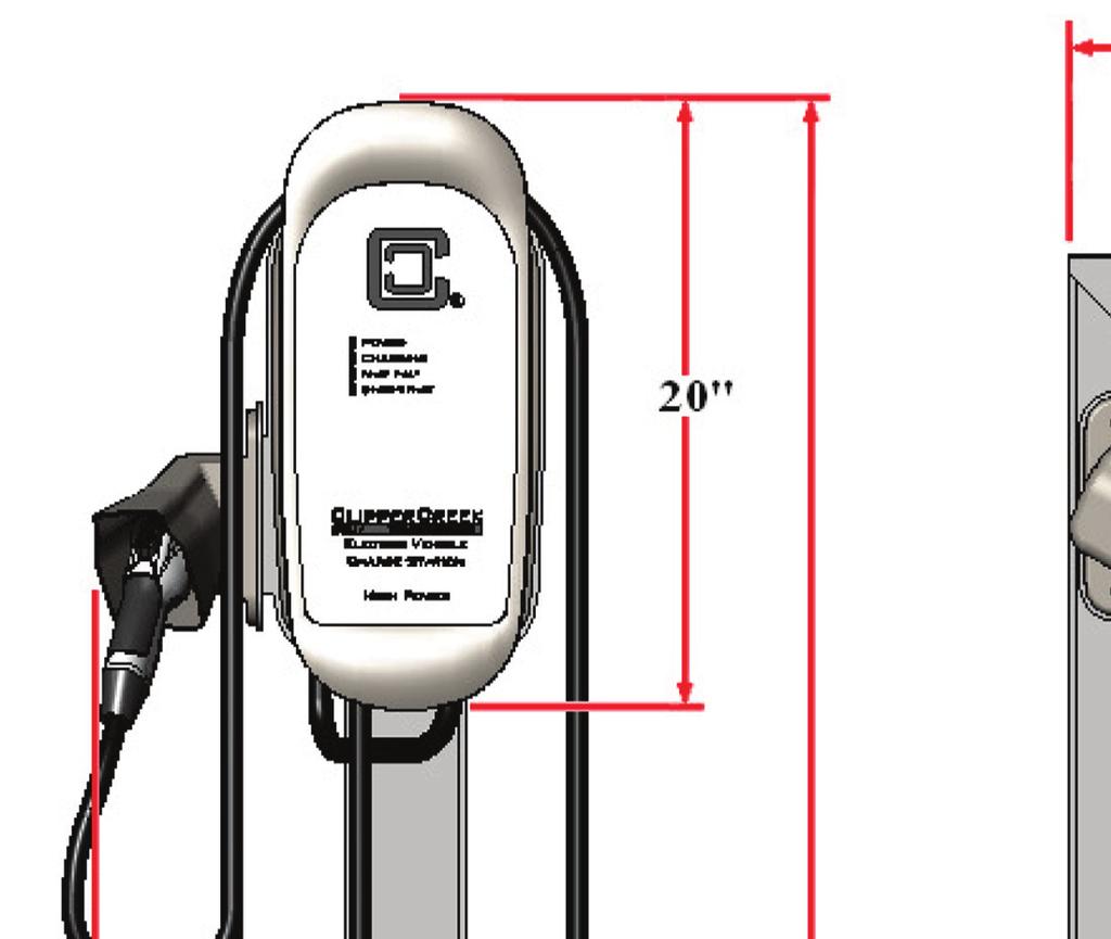
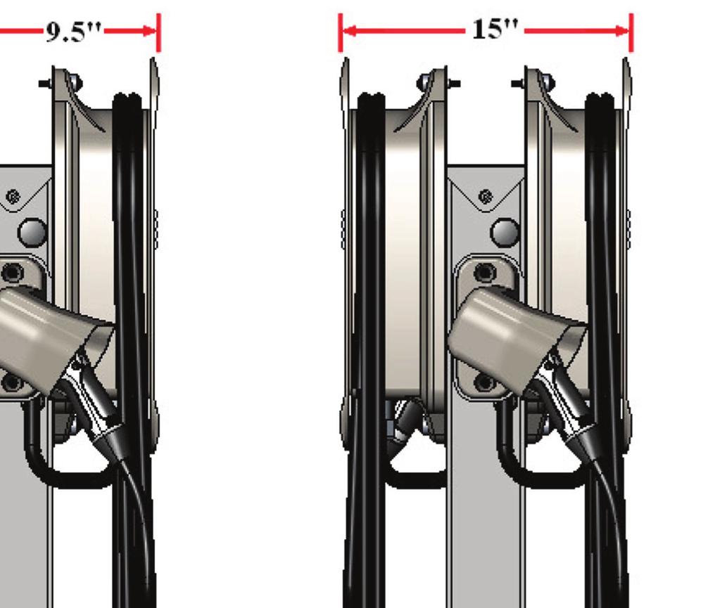
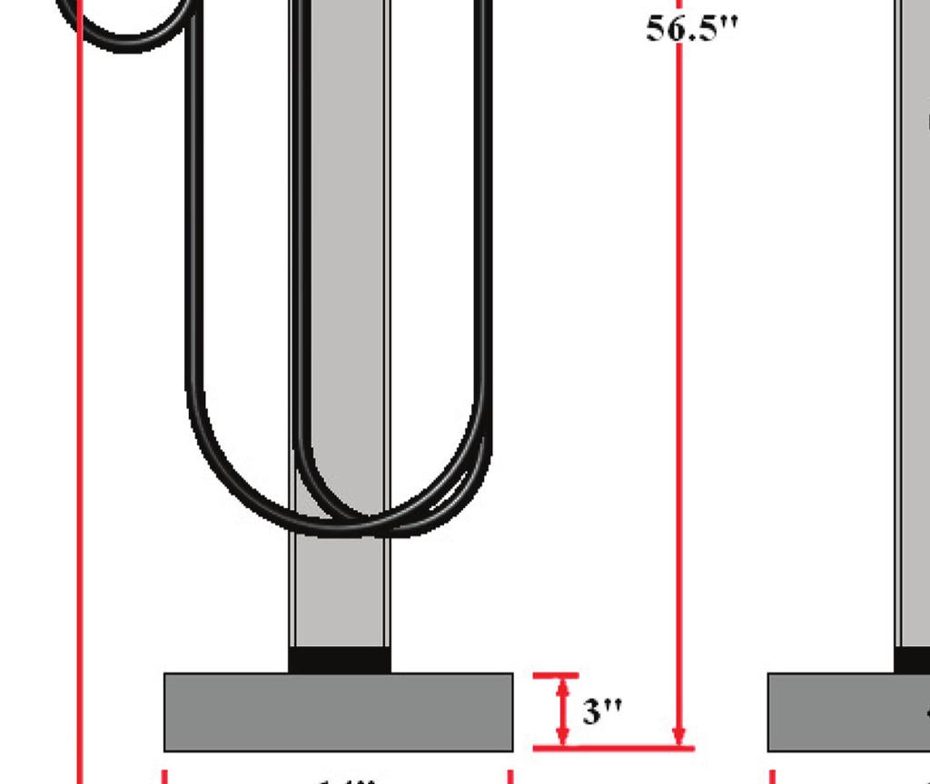
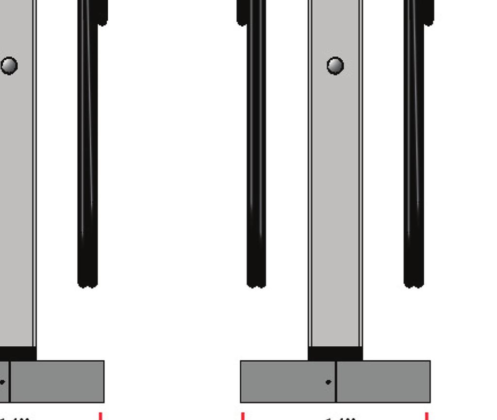
6 PEDESTAL INSTALLATION GUIDE TESLA WALL CONNECTOR SINGLE AND DUAL mount CONFIGURATION DImENSIONS Page 6

7 PEDESTAL INSTALLATION GUIDE ClipperCreek, Inc. CLIPPERCREEK HCS SINGLE AND DUAL mount CONFIGURATION DImENSIONS Page 7
8 PEDESTAL INSTALLATION GUIDE Installation Requirements Refer to the EVSE documentation to determine the appropriate circuit breaker current capacity. All conductors must be appropriately sized for the EVSE current capacity, in accordance with local and NEC electrical codes. Required Equipment for a Single-Mount Pedestal with one TESLA WALL CONNECTOR (ONE EVSE PEDESTAL): One (1) TESLA Wall Connector (EVSE). NOTE: The TESLA Wall Connector comes with a Cable Organizer for Wall Mounting Purposes only. This cable organizer is not utilized on the Pedestal Mounting System. One (1) ClipperCreek TESLA EVSE Pedestal Kit, ClipperCreek part number One (1) dedicated 208 or 240 VAC branch circuits. One (1) circuit breaker, appropriately sized with respect to the charging capacity of each EVSE. Two (2) Live Line conductors with enough length to comfortably pull all the way through and above the top of the pedestal. One (1) Ground Line conductor with enough length to comfortably pull all the way through and above the top of the pedestal. Conduit sized to fit all three conductors. Four (4) Anchor Bolts with Nuts and Washers Required Equipment for a Dual-Mount Pedestal with two TESLA WALL CONNECTORS (Two EVSE s per Pedestal): Two (2) TESLA Wall Connectors (EVSE s). NOTE: The TESLA Wall Connector comes with a Cable Organizer for Wall Mounting Purposes only. This cable organizer is not utilized on the Pedestal Mounting System. One (1) ClipperCreek TESLA EVSE Pedestal Kit, ClipperCreek part number One (1) ClipperCreek Dual-Mount TESLA Mounting Plate Kit, ClipperCreek part number Two (2) dedicated 208 or 240 VAC branch circuits. Two (2) circuit breakers, appropriately sized with respect to the charging capacity of each EVSE. Two pairs (2x2) Live Line conductors (one pair for each EVSE) with enough length to comfortably pull all the way through and above the top of the pedestal. Two (2) Ground Line conductors (One for each EVSE) or a single bonded Ground Line with enough length to comfortably pull all the way through and above the top of the pedestal. Conduit sized to fit all Live Line and Ground Line conductors. Four (4) Anchor Bolts with Nuts and Washers Required Equipment for a combo Dual-Mount Pedestal with one TESLA Wall Connector and one HCS Charging Station (Two EVSE s per Pedestal): One (1) TESLA Wall Connector (EVSE). NOTE: The TESLA Wall Connector comes with a Cable Organizer for Wall Mounting Purposes only. This cable organizer is not utilized on the Pedestal Mounting System. One (1) ClipperCreek HCS EVSE Pedestal Kit, ClipperCreek part number One (1) ClipperCreek HCS Charging Station (EVSE), part number depends on amperage selected. One (1) ClipperCreek Dual-Mount TESLA Mounting Plate Kit, ClipperCreek part number Two (2) dedicated 208 or 240 VAC branch circuits. Two (2) circuit breakers, appropriately sized with respect to the charging capacity of each EVSE. Two pairs (2x2) Live Line conductors (one pair for each EVSE) with enough length to comfortably pull all the way through and above the top of the pedestal. Two (2) Ground Line conductors (One for each EVSE) or a single bonded Ground Line with enough length to comfortably pull all the way through and above the top of the pedestal. Conduit sized to fit all Live Line and Ground Line conductors. Four (4) Anchor Bolts with Nuts and Washers Page 8
9 PEDESTAL INSTALLATION GUIDE Required Equipment for a Single-Mount Pedestal with one ClipperCreek HCS Charging Station (One EVSE per Pedestal): One (1) ClipperCreek HCS EVSE Pedestal Kit, ClipperCreek part number One (1) ClipperCreek HCS Charging Station (EVSE), part number depends on amperage selected. One (1) dedicated 208 or 240 VAC branch circuit. One (1) circuit breaker appropriately sized for the EVSE charging capacity. Two (2) Live Line conductors with enough length to comfortably pull all the way through and above the top of the pedestal. One (1) Ground Line conductor with enough length to comfortably pull all the way through and above the top of the pedestal. Conduit sized to fit all three conductors. Four (4) Anchor Bolts with Nuts and Washers Required Equipment for a Dual-Mount Pedestal with two ClipperCreek HCS Charging Stations (Two EVSE s per Pedestal): One (1) ClipperCreek HCS EVSE Pedestal Kit, ClipperCreek part number One (1) ClipperCreek Dual-Mount HCS Pedestal Kit, ClipperCreek part number Two (2) ClipperCreek HCS Charging Stations (EVSEs), part number depends on amperage selected. Two (2) dedicated 208 or 240 VAC branch circuits. Two (2) circuit breakers, appropriately sized with respect to the charging capacity of each EVSE. Two pairs (2x2) Live Line conductors (one pair for each EVSE) with enough length to comfortably pull all the way through and above the top of the pedestal. Two (2) Ground Line conductors (One for each EVSE) or a single bonded Ground Line with enough length to comfortably pull all the way through and above the top of the pedestal. Conduit sized to fit all Live Line and Ground Line conductors. Four (4) Anchor Bolts with Nuts and Washers Page 9
10 PEDESTAL INSTALLATION GUIDE Packing Lists TESLA Pedestal Kit, Standard 4 Foot, Single-Mount Part Number qty Description Pedestal Metalwork, Cap with Front and Rear Flange NOTE: this item may already be attached to the top of the pedestal Pedestal Metalwork, Base Cover Pedestal Metalwork, 4-Foot Post Pedestal Metalwork, Hole Cover Plate Pedestal Metalwork, TESLA Wall Connector Mounting Plate Machine Screw, Tapered Flat Head, 6-32 Size, 3/8 Length, Phillips Machine Screw, Tapered Flat Head, 1/4-20 Size, 3/4 Length, T27 Torx Machine Screw, Button Head, 1/4-20 Size, 1 Length, T27 Torx Hex Nut, 18-8 Stainless Steel, 5/16-18 Thread, 1/2 Width, 17/64 Height Washer, Galvanized Steel, Neoprene Bonded Seal, 1/4 ID, 5/8 OD Washer, 18-8 Stainless Steel, 5/16 screw size, 11/32 ID, 11/16 OD Plug, Plastic Push-In, 1-3/32 ID, 1-7/32 OD Plug, Plastic Push-In, 1-3/8 ID, 1-1/2 OD Plug, Plastic Push-In, 7/8 ID, 1 OD HCS Pedestal Kit, Standard 4 Foot, Single-Mount Part Number qty Description Holster, gray polycarbonate Pedestal Metalwork, Cap with Rear Flange NOTE: this item may already be attached to the top of the pedestal Pedestal Metalwork, Base Cover Pedestal Metalwork, 4-Foot Post Pedestal Metalwork, Hole Cover Plate Pedestal Metalwork, HCS Charging station Mounting Plate Machine Screw, Pan Head, 8-32, ½ Length, Phillips Machine Screw, Tapered Flat Head, 6-32 Size, 3/8 Length, Phillips Machine Screw, Tapered Flat Head, 1/4-20 Size, 3/4 Length, T27 Torx Machine Screw, Button Head, 1/4-20 Size, 1 Length, T27 Torx Machine Screw, Button Head, 1/4-20 Size, 2 Length, T27 Torx Washer, #8, Zinc, 3/16 ID, 7/16 OD Washer, Galvanized Steel, Neoprene Bonded Seal, 1/4 ID, 5/8 OD Washer, Liquid Tight Sealing, Thermoplastic, ½ or Pedestal Conduit Assembly, Standard 90 degree 1/2 NPT Fitting Conduit for HCS-60 (or higher) and 3/8 NPT for HCS-40 (or lower) Plug, Plastic Push-In, 1-3/32 ID, 1-7/32 OD Plug, Plastic Push-In, 1-3/8 ID, 1-1/2 OD Plug, Plastic Push-In, 7/8 ID, 1 OD Page 10
11 PEDESTAL INSTALLATION GUIDE Optional Orderable Items TESLA WALL CONNECTOR Dual-Mount Kit for Standard 4 Foot Pedestal (optional) Part Number qty Description Pedestal Metalwork, TESLA Wall Connector Mounting Plate Machine Screw, Tapered Flat Head, 1/4-20 Size, 3/4 Length, T27 Torx Hex Nut, 18-8 Stainless Steel, 5/16-18 Thread, 1/2 Width, 17/64 Height Washer, 18-8 Stainless Steel, 5/16 screw size, 11/32 ID, 11/16 OD HCS Dual-Mount Kit for Standard 4 Foot Pedestal (Optional) Part Number qty Description Holster, gray polycarbonate Pedestal Metalwork, Cap without Rear Flange Pedestal Metalwork, HCS Charging station Mounting Plate Machine Screw, Pan Head, 8-32, ½ Length, Phillips Machine Screw, Tapered Flat Head, 1/4-20 Size, 3/4 Length, T27 Torx Machine Screw, Button Head, 1/4-20 Size, 1 Length, T27 Torx Machine Screw, Button Head, 1/4-20 Size, 2 Length, T27 Torx Washer, #8, Zinc, 3/16 ID, 7/16 OD Washer, Galvanized Steel, Neoprene Bonded Seal, 1/4 ID, 5/8 OD Washer, Liquid Tight Sealing, Thermoplastic, ½ or Pedestal Conduit Assembly, Standard 90 degree 1/2 NPT Fitting Conduit for HCS-60 (or higher) and 3/8 NPT for HCS-40 (or lower) V Ground Fault Receptacle Kit (optional)* Part Number qty Description Plug, Knockout Bushing, OD, 3/4 Trade Size Aperture GFCI Ground Fault Receptacle, 15A, 125V, NEMA 5-15R, Single Socket with Switch Gang Box, Single, Silver Metal Weatherproof Receptacle Cover, Clear, Single Gang, 2-3/4 Depth * The Ground Fault Receptacle Kit includes a 120VAC GFCI receptacle and housing. It may be installed at the knock-outs located 24 inches above the base on either side of the pedestal. Page 11

12 PEDESTAL INSTALLATION GUIDE: MAIN PEDESTAL MAIN PEDESTAL SETUP BOTH HCS & TESLA INSTALLATIONS REQUIRE THESE STEPS 1. Concrete Pad Requirements The location, dimensions, and composition of the concrete pad underlying the pedestal should always adhere to local building codes. The following dimensions are minimum recommended values. Always verify that installation plans adhere to local code requirements prior to proceeding. The pad area must be a minimum of 18 to a side. The concrete must be poured a minimum depth of 18. If there is no bumper block, the center of the pedestal base should be situated 36 behind the curb. If a bumper block is in place, the center of the pedestal base should be situated 12 behind the curb. 2. Anchor Bolt Placement A minimum of four (4) anchor bolts must be embedded in the concrete pad for the purposes of securing the pedestal post. The pedestal base is designed to permit the anchor bolts to be arranged in many configurations, including the following: Use the Pedestal Base Pattern Template: To better facilitate the installation of the anchor bolts, a cardboard template in the shape of the pedestal base is included in the pedestal kit. This template is provided as a knock-out piece on the back of the cardboard box in which the cover plate is packaged. The template is specific for two bolt patterns: the standard 10 x 10 pattern and an alternate 5.25 x 11.1 rectangular pattern. Page 12
 3/8 anchor bolts in a 5.25 by 11.1 rectangular pattern.")
13 PEDESTAL INSTALLATION GUIDE: MAIN PEDESTAL For the Standard 10 Square Pattern: Arrange four (4) 1/2 or 3/8 anchor bolts in a 10 square pattern. This placement corresponds to the corner cutouts in the pedestal base. For the Alternate 5.25 x 11.1 Rectangular Pattern: Arrange four (4) 3/8 anchor bolts in a 5.25 by 11.1 rectangular pattern. This placement corresponds to the short inner cutouts in the pedestal base. For the Alternate 10 x 4.75 Rectangular Pattern: Arrange four (4) 1/2 anchor bolts in a 10 by 4.75 rectangular pattern. This placement corresponds to fall within the long inner cutouts in the pedestal base. Maximum Anchor Bolt Height: The anchor bolts should not protrude more than 3 above the surface of the concrete pad. 3. Mounting the Pedestal Post Once the concrete pad with anchor bolts has been prepared and the three service conductors have been pulled through the underground conduit, the pedestal post may be placed. NOTE: DO NOT remove the tape at the bottom of the pedestal. This tape is provided for finish and weather protection of the pedestal post. Feed the three service conductors up through the inside of the pedestal post. The conductors must be of sufficient length to pass beyond the top of the pedestal so that final connections can be worked with comfortably at a later step. Align the pedestal post base notches with the four anchor bolts and ease it into place. NUTS AND WASHERS MAY BE USED UNDER THE PEDESTAL BASE TO ADJUST THE VERTICAL ALIGNMENT OF THE PEDESTAL SHOULD THE CONCRETE PAD NOT BE LEVEL. Secure the pedestal post base to the concrete anchor bolts using appropriately sized nuts and washers. The anchor bolts, nuts and washers used for the installation of the pedestal base are not included in the pedestal kit and must be purchased separately. Page 13


14 PEDESTAL INSTALLATION GUIDE: MAIN PEDESTAL 4. Install the Pedestal Base Cover A two-piece pedestal base cover set is included in the pedestal kit. The purpose of the pedestal base cover is to beautify the installation and to protect against injury from protruding anchor bolts. The two covers are of an identical overlapping design. Slide one cover on the front side of the pedestal base until the center notch surrounds half of the pedestal post. Slide the other cover onto the rear side in the same manner. Ensure that the flanges of each cover piece are tucked inside of the opposite cover. Align the four screw holes of each cover piece with the corresponding screw holes on the opposite cover. Secure each cover piece to the other with four (4) #6-32 x 3/8 flat-head tapered screws using a #2 Philips- head screwdriver. 5. Remove the Pedestal Post Cap A pedestal cap is provided to cover the opening to protect the conductors and inner pedestal from the elements. It may have already been assembled on the post for protection during shipping. Temporarily remove this cap for additional access to electrical connections. YOU HAVE NOW COMPLETED INSTALLATION OF THE MAIN PEDESTAL. PLEASE REFER TO TESLA WALL CONNECTOR AND/OR CLIPPERCREEK HCS INSTALLATION STEPS ACCORDING TO THE CONFIGURATIONS DESIRED. Page 14


15 PEDESTAL INSTALLATION GUIDE: TESLA WALL CONNECTOR TESLA WALL CONNECTOR INSTALLATION REqUIRES THESE STEPS THESE STEPS ARE TO BE COmPLETED AFTER THE main PEDESTAL INSTALLATION FOR THE TESLA WALL CONNECTOR CONFIGURATIONS ONLy. REPEAT EACH STEP FOR DUAL-mOUNTED CONFIGURATIONS ON THE OPPOSITE SIDE OF THE PEDESTAL: 1. INSTALL THE TESLA WALL CONNECTOR mounting PLATE A mounting plate is affixed to the front of the pedestal post to provide a flat and rigid base on which the wall connector can be mounted. In the case of a Dual-Mount installation, a second mounting plate is affixed to the opposite side of the pedestal post. Hold the wall connector mounting plate against the front side of the pedestal post as shown. Align the two screw holes of the mounting plate with the two corresponding threaded inserts on the front of the pedestal post. To properly position the Mounting Plate use a T27 Torx driver and two (2) 1/4-20 x 3/4 Torx flat-head tapered screws. Begin with the top position first and tighten each of the 1/4-20 x 3/4 Torx flat-head tapered screws about halfway in. Firmly tighten both screws until the head of the screw is flush with the surface of the mounting plate. For Dual-Mount installations, repeat on the opposite side. 2. mount THE TESLA mounting BRACKET TO THE mounting PLATE With the main mounting plate in place, the pedestal is now ready for the TESLA Mounting Bracket. Align the TESLA Mounting Bracket (which is included with the TESLA Wall Connector) with the two studs on the Mounting Plate. Place one 11/16 OD stainless steel washer over each stud. Secure the washers and Mounting Bracket to the Mounting Plate by firmly tightening one 5/16-18 Hex Nut onto each stud. For an installation with two TESLA EVSE s affixed to the same post, repeat the previous steps for the opposite side. Page 15


16 PEDESTAL INSTALLATION GUIDE: TESLA WALL CONNECTOR 3. PREPARE THE TESLA WALL CONNECTOR FOR PEDESTAL mounting With the TESLA Mounting Bracket in place, the pedestal is now ready for a TESLA Wall Connector to be mounted. For Dual-Mount Installations, repeat the steps below for the opposite side. Using a Torx T20 driver, remove the two security screws from the bottom of the TESLA Wall Connector. Keep these in a safe place to use later. Release the front cover by gently pulling it towards you. CAUTION: The ribbon cable may be attached. If so, disconnect the ribbon cable from inside the main enclosure to fully release the front cover. Do not damage the ribbon cable. Disconnect the ground wire from the terminal block and push it out of the way to avoid damaging it when completing the next step. Use a 1 ¼ (32mm) hole saw to remove the power entry knock-out from the back of the connector. CAUTION: When using the hole saw, be careful not to damage internal components. Reconnect the Ground wire to the terminal block. Page 16


 and a ratchet wrench with 8mm socket to tighten")
17 PEDESTAL INSTALLATION GUIDE: TESLA WALL CONNECTOR 4. mount THE TESLA WALL CONNECTOR TO THE PEDESTAL The TESLA Wall Connector has provisions for 1 (25 mm) conduit. Align the TESLA Wall Connector over the Mounting Bracket. Attach the grounding wire. Fasten the TESLA Wall Connector onto the Mounting Bracket using the flange screws (supplied with the TESLA Wall Connector) and a ratchet wrench with 8mm socket to tighten firmly into position. Use caution to prevent pinching wires. For Dual-Mount Installations, repeat on the opposite side. Page 17

18 PEDESTAL INSTALLATION GUIDE: TESLA WALL CONNECTOR 5. CONNECT THE WIRING NOTE: For most branch circuits of 100A, use 3 AWG (26.7 mm2), 75 C (167 F) copper wire. For installations less than 100A, use conductors that are sized according to local electrical codes. WARNING: Do not connect service wiring until you have read and fully understand the pages in the document titled Service Wiring. If you are uncertain about the type of power available at the service panel, consult your local utility, or contact TESLA for assistance. Turn off the Power. WARNING: RISK OF ELECTRIC SHOCK! Before connecting the wiring, use a volt meter to confirm that NO POWER is available at the service wiring or terminals. Pull the service wiring into the TESLA Wall Connector. Strip wires 3/8 (10 mm) Connect wiring to the terminal block. Connect L1 to Black, L2/N to Red, and Ground to one of the two available Ground connectors, as shown. NOTE: Maximum size of Ground wire is 4 AWG. Tighten L1 and L2 screws to lb-in, depending on the wire gauge. Tighten Ground screw according to the table: For Dual-Mount Installations, be aware that the TESLA Wall Connector EVSE s may have different ratings. Extra precaustion should be taken to ensure the correct wiring connections per EVSE. Page 18

19 PEDESTAL INSTALLATION GUIDE: TESLA WALL CONNECTOR 6. CONFIRm A SUCCESSFUL INSTALLATION Set the dip switches, located in the lower right-hand portion of the connector, to the test setting shown here. Use a pointed object such as a pen. While holding the front cover near the TESLA Wall Connector, re-connect the Ribbon Cable be aligning the cable, as shown. Hang the front cover over the hinge located at the top of the connector. NOTE: Do not secure the front cover yet. Turn on the Power Hold the RESET button for five seconds. This button is located on the lower right side of the TESLA Wall Connector. You should now hear the contacts close and see the lights sequentially illuminate green. If the RED error light illuminates or flashes, refer to the troubleshooting table in the TESLA Wall Connector Installation Guide. If the RED error light is not illuminated or flashing, continue with the next two steps. For Dual-Mount Installations, repeat on the opposite side. Page 19


20 PEDESTAL INSTALLATION GUIDE: TESLA WALL CONNECTOR 7. SET OPERATING CURRENT Turn off the power. WARNING: RISK OF ELECTRIC SHOCK! Before continuing, use a volt meter to confirm that NO POWER is available at the service wiring or terminals. Open the front cover and hold it with one hand while completing the next step. CAUTION: Do not release the front cover or allow it to hang from the ribbon cable. Doing so can damage the ribbon cable s connectors. Adjust the dip switches to set the operating current based on the type of breaker being used. Use a pointed non-conductive object such as a plastic pen. NOTE: Power MUST be turned off before setting or changing DIP switches. If you set DIP switches with the power on, not only is it dangerous, because of the risk of electric shock (see warning above), but the changes are not recognized. Extra precaution should be used for Dual-Mount Installations. EVSE s may look the same on the surface but have different ratings. Set operating currents accordingly. Page 20


21 PEDESTAL INSTALLATION GUIDE: TESLA WALL CONNECTOR 8. RE-INSTALL THE PEDESTAL POST CAP The pedestal cap is provided to cover the opening to protect the conductors and inner pedestal from the elements. For either Single or Dual-Mounted TESLA Wall Connector pedestals, use the pedestal cap provided that has flanges on both sides. For Combo HCS and TESLA configurations, use the pedestal cap provided with the flange on the TESLA side of the pedestal. 9. INSTALL THE COVER PLATE The cover plate is provided to cover the electrical access hole for Single-Mount Pedestals only. Skip this step if you are installing a Dual-Mount. Secure the cover plate to the Single-Mount Pedestal using two (2) 1/4-20 x 3/4 Torx flat-head tapered screws using a T27 Torx driver until the screw head is flush with the surface of the mounting plate. 10. SECURE COVER AND POWER UP Reposition the front cover over the unit, aligning the five tabs on the back of the front cover with their corresponding slots. Starting at the bottom and working upwards, press firmly on both sides of the front cover until it clicks into place. Using a T20 torx driver, re-attach the two security screws that you removed in STEP THREE. Turn on the Power. you HAVE NOW FINISHED INSTALLING THE TESLA WALL CONNECTOR ONTO THE PEDESTAL mounting SySTEm. REFER TO THE TESLA WALL CONNECTOR INSTALLATION GUIDE FOR TROUBLE- SHOOTING AND ADDITIONAL INFORmATION. Page 21

22 PEDESTAL INSTALLATION GUIDE: CLIPPERCREEK HCS clippercreek HCS installation REQUIREs THESE STEPS These steps ARE to be completed AFTER the main pedestal installation for the ClipperCreek HCS configurations only. REpeat each step for dual-mounted configurations on the opposite side of the pedestal: 1. Install the Conduit Assembly Knock-out the 1½ plastic plug located 10 down from the top of the pedestal on the left side. Connect the following to the Pedestal Post in the order: a) The Standard 90 degree 1/2 NPT Fitting b) The ½ liquid tight sealing washer c) The open pedestal hole d) The first locknut from the NPT Fitting (inside of the pedestal) Tighten so that the bottom opening of the NPT Fitting is facing downward. For Dual-Mount Installations, repeat on the opposite side. 2. Install the WALL CONNECTOR Mounting Plate A mounting plate is affixed to the front of the pedestal post to provide a flat and rigid base on which the ClipperCreek HCS can be mounted. In the case of a Dual-Mount Installation, a second mounting plate is affixed to the opposite side of the pedestal post. Hold the mounting plate against the front side of the pedestal post as shown. Align the center screw hole of the mounting plate with the corresponding top threaded insert on the front of the pedestal post. Secure the mounting plate to the pedestal with one (1) 1/4-20 x 3/4 Torx flat-head tapered screw using a T27 Torx driver. Tighten until the head of the screw is flush with the surface of the mounting plate. For Dual-Mount Installations, repeat on the opposite side. Page 22


23 PEDESTAL INSTALLATION GUIDE: CLIPPERCREEK HCS 3. Mounting a Single Charging station to the Pedestal With the mounting plate in place, the pedestal is now ready for a single charging station to be mounted. Place a 1/4 Neoprene-bonded sealing washer around the shaft of each of the two (2) 1/4-20 x 2 Torx buttonhead screws. The metal portion of the washer should face the head of the screw while the neoprene should face the tip of the screw. There are two different styles of HCS plastic angle washers. The correct style to use with the HCS Pedestal is the Perpendicular Screw Mount. These washers are included with the HCS Charging Station and do not accompany this kit. Align the two screw holes on the top and bottom of the charging station with the corresponding threaded inserts on the mounting plate. Use a T27 Torx driver to secure the top of the charging station first using one (1) 1/4-20 x 2 Torx button-head screws with neoprene washer and HCS Plastic Angle Washer as shown below.do not over-tighten. Secure the bottom of the charging station using one (1) 1/4-20 x 2 Torx button-head screws with neoprene washer and HCS Plastic Angle Washer. For an installation with two charging stations affixed to the same post, repeat the previous steps for the opposite side. 4. Connect the Wiring The HCS has a flexible conduit extension with three conductors. These conductors must be routed through the side of the pedestal and the ninetydegree ½ NPT for connection. Trim the EVSE conduit to length. The recommended length to remain is 12 inches as measured from the bottom of the EVSE. Route the three conductors that come through the EVSE s flexible conduit through the NPT connection and into the Pedestal Post. No disassembly of the NPT Fitting is required. Push the conduit onto the NPT Fitting ferrule and then tighten the domed sealing nut on the NPT fitting. For Dual-Mount Installations, repeat on the opposite side. All conductor and ground lug connections inside the Pedestal Post must be completed at this time. The top access hole will be blocked after this step. 5. Re-Install the Pedestal Post Cap The pedestal cap is provided to cover the opening to protect the conductors and inner pedestal from the elements. Install the appropriate pedestal cap for a single-mount or dual-mount charging station installation as described below. For Single-Mount Installations: Single-mount charging station installations utilize the standard post cap provided in the pedestal kit. This post cap includes a flange on one side. Place the post cap onto the top of the pedestal, with the flange facing the rear. Align the screw holes on each side of the post cap with the corresponding threaded inserts on the sides of the pedestal. Place a 1/4 Neoprene-bonded sealing washer around the shaft of two (2) 1/4-20 x 1 Torx button-head screws. The metal portion of the washer should face the head of the screw while the neoprene should face the tip of the screw. Secure the cap to the pedestal with the two (2) 1/4-20 x 1 Torx button-head screws (with washers) using a T27 Torx driver. Page 23

 1/4-20 x 1 Torx button-head screws.")
 1/4-20 x 1 Torx button-head screws (with washers) using a T27 Torx driver. 6.")
24 PEDESTAL INSTALLATION GUIDE: CLIPPERCREEK HCS FOR DUAL-mOUNT INSTALLATIONS: Dual-Mount installations utilize a replacement post cap provided in the Dual- Mount Kit. This post cap lacks a flange at the rear. Place the post cap onto the top of the pedestal. Align the screw hole on each side of the post cap with the corresponding thread insert on the side of the pedestal. Place a 1/4 Neoprene-bonded sealing washer around the shaft of two (2) 1/4-20 x 1 Torx button-head screws. The metal portion of the washer should face the head of the screw while the neoprene should face the tip of the screw. Secure the cap to the pedestal with the two (2) 1/4-20 x 1 Torx button-head screws (with washers) using a T27 Torx driver. 6. INSTALL THE COVER PLATE The cover plate is provided to cover the electrical access hole for Single-Mount Pedestals only. Skip this step if you are installing a Dual-Mount. Secure the cover plate to the Single-Mount Pedestal using two (2) 1/4-20 x 3/4 Torx flat-head tapered screws using a T27 Torx driver until the screw head is flush with the surface of the mounting plate. 7. INSTALL THE HOLSTER A holster has been provided with this kit to stow the vehicle connector. Place a #8 washer around the shaft of each of the two (2) 8-32 pan head screws. Secure the Holster to the Mounting Plate as shown. For an installation with two charging stations affixed to the same post, repeat the previous steps for the opposite side. Page 24

25 PEDESTAL INSTALLATION GUIDE: CLIPPERCREEK HCS 8. Mounting Two CLIPPERCREEK HCS EVSE S to the Pedestal For an installation with two charging stations affixed to the same post, repeat the previous steps 7 through 11 for the opposite side. 9. Wrap and Stow the Vehicle Connector Loosely wrap the cable around the HCS. Stow the Vehicle Connector in the holster. The button does not need to be pressed, simply insert until you hear the click to lock in place. Verify the safety of the installation prior to turning on the circuit breaker. Refer to the ClipperCreek HCS User s Guide for further operational and maintenance information. YOU HAVE NOW FINISHED INSTALLING THE CLIPPERCREEK HCS ONTO THE PEDESTAL MOUNTING SYSTEM. REFER TO THE CLIPPERCREEK HCS INSTALLATION GUIDE FOR TROUBLESHOOTING AND ADDITIONAL INFORMATION. Page 25
26 PEDESTAL INSTALLATION GUIDE CUSTOMER SUPPORT Call your ClipperCreek. Inc. Service Representative at any time, 24 hours a day, at the number below. PLEASE HAVE THE MODEL NUMBER AND SERIAL NUMBE R AVAILABLE WHEN YOU CALL. This information is printed on the label. If your call is made after business hours or on weekends, please leave your name, telephone number, the unit serial number, and a brief description of the problem. A Service Representative will call back at the earliest opportunity. Distributor Service Number Here To contact ClipperCreek, Inc. directly for service, call (530) from Monday to Friday between 8:00 am and 5:00 pm Pacific Standard Time. Visit us at Page 26
27 PEDESTAL INSTALLATION GUIDE WARRANTY INFORMATION LIMITED WARRANTY ELECTRIC VEHICLE SUPPLY EQUIPMENT and ACCESSORIES ClipperCreek, Inc Kemper Road, Suite E Auburn, California Telephone: information@clippercreek.net ClipperCreek shall provide the following warranty with respect to the products to representative, its sub-representatives and their customers: Product 3-year parts, 3-year factory labor: ClipperCreek, Inc. warrants this product to be free from defects in material and workmanship. The warranty period shall commence on the date of installation date (first use).the product installation date must be evidenced and communicated to ClipperCreek by way of the warranty registration card (or its equivalent). The warranty registration card must be filled out completely and accurately, and returned to ClipperCreek within 30 days after installation, and the product installation date shall be within 6 months after the purchase date. If a product installation date is not communicated to ClipperCreek as described above, the product purchase date shall serve as the warranty commencement date. If this product is defective in materials or workmanship during the warranty period, ClipperCreek will, at its option, repair or replace the product. Repair parts and/or replacement products may be either new or reconditioned at ClipperCreek s discretion. This limited warranty does not cover service or parts to repair damage due to improper installation or use, including but not limited to improper connections with peripherals, external electrical faults, accident, disaster, misuse, abuse or modifications to the product not approved in writing by ClipperCreek. Any service repair outside the scope of this limited warranty shall be at applicable rates and terms then in effect. This warranty covers factory parts and factory labor only; it does not cover field service or removal and replacement of the product or any other costs. All other express and implied warranties for this product including the warranties of merchantability and fitness for a particular purpose are hereby disclaimed. Some states do not allow the exclusion of implied warranties or limitations on how long an implied warranty lasts, so the above limitation may not apply to you. If this product is not as warranted above, your sole and exclusive remedy shall be repair or replacement as provided above. In no event will ClipperCreek, any of its authorized sales and service representatives, or its parent company be liable to customer or any third party for any damages in excess of the purchase price of the product. This limitation applies to damages of any kind including any direct or indirect damages, lost profits, lost saving or other special, incidental, exemplary or consequential damages whether for breach of contract, tort or otherwise or whether arising out of the use of or inability to use the product, even if ClipperCreek or an authorized ClipperCreek representative or dealer has been advised of the possibility of such damages or of any claim by any other party. Some states do not allow the exclusion or limitation of incidental damages for some products, so the above limitation or exclusion may not apply to you. This warranty gives you specific legal rights, and you may also have other rights which may vary from state to state. To obtain warranty service: Call your nearest authorized Service Representative or ClipperCreek at the above number. You will receive information as to how service for the product will be provided. If you mail or ship the product in for service, you must insure the product, prepay all shipping charges, and properly pack it for shipment in its original shipping container or its equivalent. You are responsible for all loss or damage that may occur in transit. You must provide proof of purchase of the product and the purchase date before any warranty service can be performed. Page 27
28 PEDESTAL INSTALLATION GUIDE ClipperCreek, Inc Kemper Rd., Suite E Auburn, CA Page 28
Innovative Infrastructure for Electric and Hybrid Vehicles PEDESTAL EXTENSION KIT INSTALLATION GUIDE
 Innovative Infrastructure for Electric and Hybrid Vehicles PEDESTAL EXTENSION KIT INSTALLATION GUIDE PLEASE NOTE: This installation guide includes the latest information at the time of printing. ClipperCreek,
Tilting Flat Panel Wall Mount Installation Guide
 Tilting Flat Panel Wall Mount Installation Guide Model: A580TM Easy installation Built-in level for easy positioning Safety bolts lock the TV on the mount Easy to adjust tilt angles: +5 to -15 degrees
Tilting, Swiveling & Rotating Flat Panel Wall Mount
 Tilting, Swiveling & Rotating Flat Panel Wall Mount Model: VXA980TC +5 to -5 +5 to -5 Supports most 0-80 Flat Panel TVs Maximum Weight Capacity: 32 lbs. Supports VESA Sizes up to 600x500 For technical
Tilting & Swiveling Plasma/LCD Flat Panel Wall Mount Installation Guide Model: A380SM
 Tilting & Swiveling Plasma/LCD Flat Panel Wall Mount Installation Guide Model: A380SM Easy installation Built-in level for easy positioning Corrective leveling adjustments after installation Forward /
One Shelf, Wall Mounted A/V Component Stand Installation Guide Model: EX101SS
 One Shelf, Wall Mounted A/V Component Stand Installation Guide Model: EX0SS For technical assistance or troubleshooting please call -855-994-3832. This product is intended for use only with Audio/Video
NOVA-EXT Versatile Projector Mount Model: NOVA-EXT
 INSTALLATION MANUAL NOVA-EXT Versatile Projector Mount Model: NOVA-EXT NORTH AMERICA 3130 East Miraloma Avenue Anaheim, CA 92806 USA USA and Canada Phone: 800-368-9700 Fax: 800-832-4888 Other Locations
Install Instructions. NewAge Steel Welded Tall Locker
 Kit Contains Full Width Adjustable Steel Shelves (4) Height-Adjustable Steel Leveling Legs (4) Aluminum Door Trim (2) 2.5 x ¼ Cabinet Mounting Lag Bolts (4) Large Zinc Plated Mounting Washers (4) 5/8 x
RESIDENTIAL MOTORIZED STORAGE UNIT
 BY V-BRO PRODUCTS RESIDENTIAL MOTORIZED STORAGE UNIT Model: GGR220 INSTALLATION AND OPERATING INSTRUCTIONS Distributed Exclusively by V-BRO PRODUCTS For technical questions and replacement parts, please
INSTALL INSTRUCTIONS WELCOME TO THE NEWAGE PERFORMANCE CABINETRY SERIES NEWAGE STEEL WELDED CABINETRY
 NEWAGE STEEL WELDED CABINETRY WELCOME TO THE NEWAGE PERFORMANCE CABINETRY SERIES ALL CABINETS MUST BE MOUNTED TO STUDS ON A SECURE WALL, AS PER THESE INSTRUCTIONS. FAILURE TO DO SO MAY RESULT IN SERIOUS
MaxLite Linear Strip ECO Series
 General Safety Information To reduce the risk of death, personal injury or property damage from fire, electric shock, falling parts, cuts/abrasions, and other hazards read all warnings and instructions
GB-AVSTOR5 Ceiling Equipment Storage Box with Pipe Coupler
 Ceiling Equipment Storage Box with Pipe Coupler INSTALLATION INSTRUCTIONS CREATING POSITIVE CUSTOMER EXPERIENCES 9534-500-021-00 Contents Weight Limit... 2 Warning Statements... 2 Installation Tools...
Installation Instructions Hinged Roof Rack
 Installation Instructions Hinged Roof Rack Application: Jeep Wrangler Unlimited 2004 - Current Part Number: 41435-01 www.bestop.com - We re here to help! Visit our web site and click on Ask a Question
Tilting & Swiveling Flat Panel Wall Mount Installation Guide Model: AXS2040
 Tilting & Swiveling Flat Panel Wall Mount Installation Guide Model: AXS2040 20-40 66 lbs. Supports VESA sizes up to: 200x200 For technical assistance or troubleshooting please call 1-855-994-2825 or visit
Installation Procedures For Corvette Basic/C-6 SNS 28
 Installation Procedures For 2005-2013 Corvette Basic/C-6 SNS 28 Warning: Please read directions completely before starting. If you have any questions please contact BMPP before beginning your installation.
LC200DS1 Double Stud Articulating Wall Mount for Flat Panel Screens up to 32" with up to 200mm x 200mm VESA Mounting Patterns
 Page 1 of 6 LC200DS1 Double Stud Articulating Wall Mount for Flat Panel Screens up to 32" with up to 200mm x 200mm VESA Mounting Patterns A multi-position dual articulating arm for flat screens up to 60
Installation Procedures 2015 Corvette C-7 Z06 With Carbon Fiber Kit SNS 50a
 Installation Procedures 2015 Corvette C-7 Z06 With Carbon Fiber Kit SNS 50a Warning: Please read directions completely before starting. If you have any questions please contact BMPP before beginning your
Assembly Instructions and Parts Manual JPSF-1 Fence and JPSR Rail Set
 Assembly Instructions and Parts Manual JPSF-1 Fence and JPSR Rail Set WALTER MEIER (Manufacturing) Inc. 427 New Sanford Road LaVergne, Tennessee 37086 Part No. M-708482 Ph.: 800-274-6848 Revision C2 02/2013
Loading Dock Safety Gate
 Installation Instructions/Operation and Maintenance Manual Models LDSG-120-PCY LDSG-144-PCY Table of Contents Product Information...2 Parts List...3 Installation Instructions...5 Operation...13 Inspection
Installation Instructions
 Installation Instructions 30 Built-In Wall Oven with Microwave JTP86, JT965 If you have questions, call 1.800.GE.CARES or visit our website at: ge.com Before You Begin Read these instructions carefully
ADJUSTABLE MOUNTING POST
 C Part Number 069 B EACH CARTON CONTAINS D Floor Mounting Kit A. Bottom Post Assembly B. Top Post Assembly C. Flange Head Bolts (x2) D. Floor Mounting Kit. 5/8 Wx/6 Hx0 L framing channels (x2) 2. /8-6x4
Installation Instructions Cage Kit JK Unlimited (4-Dr) Part # 76902
 Part # 76902") Please read instructions entirely before installing this product. Drilling is required to install this part. Parts Included Qty Parts Included Qty Driver Front Upright 1 Pass Side Drill Template (7289)
Please read instructions entirely before installing this product. Drilling is required to install this part. Parts Included Qty Parts Included Qty Driver Front Upright 1 Pass Side Drill Template (7289)
INSTALLATION INSTRUCTIONS
 INSTALLATION INSTRUCTIONS Universal Short Throw Projector Arm Model: UNI-STA/UNI-EXT NORTH AMERICA 3130 East Miraloma Avenue Anaheim, CA 92806 USA USA and Canada Phone: 1-800-368-9700 Fax: 1-800-832-4888
M ACS Instructions
 APPLICABLE MODELS: Nissan Frontier 2005 and up short bed with Utili-Trak mounting rails PACKAGE CONTENTS 00-0060-M-01-1205 ACS Instructions Leitner Designs 25675 Taladro Circle Unit E Mission Viejo, CA
Model DB Disc Caliper Brake AIR CHAMP PRODUCTS. User Manual. (i) MTY (81)
 MTY (81)") DIST. AUTORIZADO MEX (55) 53 63 3 3 QRO (44) 95 7 60 MTY (8) 83 54 0 8 AIR CHAMP PRODUCTS User Manual Model DB Disc Caliper Brake (i) FORM NO. L-00-G-030 MEX (55) 53 63 3 3 MTY (8) 83 54 0 8 DIST. AUTORIZADO
DIST. AUTORIZADO MEX (55) 53 63 3 3 QRO (44) 95 7 60 MTY (8) 83 54 0 8 AIR CHAMP PRODUCTS User Manual Model DB Disc Caliper Brake (i) FORM NO. L-00-G-030 MEX (55) 53 63 3 3 MTY (8) 83 54 0 8 DIST. AUTORIZADO
Assembly Instructions and Parts Manual JPSF-1 Fence and JPSR Rail Set #
 Assembly Instructions and Parts Manual JPSF-1 Fence and JPSR Rail Set #1002493 JET 427 New Sanford Road LaVergne, Tennessee 37086 Part No. M-708482 Ph.: 800-274-6848 Revision C3 02/2014 www.jettools.com
INSTALLATION INSTRUCTIONS
 INSTALLATION INSTRUCTIONS Universal Swingout Arm for 37 to 47 Flat Panels Model: AM80 NORTH AMERICA 3130 East Miraloma Avenue Anaheim, CA 92806 USA USA and Canada Phone: 1-800-368-9700 Fax: 1-800-832-4888
Installation Procedures For 2013 Mustang V-6 and 5.0
 Installation Procedures For 2013 Mustang V-6 and 5.0 Warning: Please read directions completely before starting. If you have any questions please contact BMPP before beginning your installation.. Also
Manual Carton Closing Staplers
 Operator s Manual Manual Carton Closing Staplers SHB00-A Item No. 6400 -/8" Crown Carton Closing Stapler 5/8" and /4" (5mm and 8mm) Ask for Genuine INTERCHANGE A58 and A4 Staples SHB50-C Item No. 640 -/4"
Installation Procedures Maserati Gran Turismo Sport SNS 85
 Installation Procedures 2012-2017 Maserati Gran Turismo Sport SNS 85 Warning: Please read directions completely before starting. If you have any questions please contact BMPP before beginning your installation.
Installation and Assembly: Articulating Swivel Arm for 37" - 60" Flat Panel Displays
 Installation and Assembly: Articulating Swivel Arm for 37" - 60" Flat Panel Displays Models: PLA60, PLA60-S, PLAV60, PLAV60-S Max UL Load Capacity: 175 lb (79 kg) 2300 White Oak Circle Aurora, Il 60502
SB-WM-ART2-L-BL SB-WM-ART2-XL-BL
 SB-WM-ART2-L-BL SB-WM-ART2-XL-BL Weatherproof Universal Dual-Arm Articulating Mount for Large TVs INSTALLATION MANUAL WARNING The maximum weight of this wall mount is 150 lbs (68.04 kg). Use with heavier
STOP. V00029AC Rev. 04 READ ALL OF THE FOLLOWING INSTRUCTIONS BEFORE REMOVING CABINET FROM SKID TOOL LIST. NET-ACCESS S-Type Network Cabinets
 Rev. 04 STOP READ ALL OF THE FOLLOWING INSTRUCTIONS BEFORE REMOVING CABINET FROM SKID NET-ACCESS S-Type Network Cabinets -Phillips screwdriver -Flatblade screwdriver -22mm socket wrench -15mm socket wrench
Single Flex and Double Flex Couplings (i)
") Single Flex and Double Flex Couplings (i) FORM NO. L00G00 In accordance with Nexen s established policy of constant product improvement, the specifications contained in this manual are subject to change
Single Flex and Double Flex Couplings (i) FORM NO. L00G00 In accordance with Nexen s established policy of constant product improvement, the specifications contained in this manual are subject to change
Broadband Step-Up Transformer. User Manual
 Broadband Step-Up Transformer User Manual 990-1930 09/2004 Introduction Introduction About this unit The APC Step-Up Transformer provides 220 V power from 60 VAC Broadband cable systems. Safety Electrical
Equilibrium. Conference Table. Installation Instruction. Revision B 11/07/16
 Equilibrium Conference Table Installation Instruction Revision B 11/07/16 Equilibrium End User Agreement Enwork Equilibrium table bases must be installed directly onto a four inch minimum thickness concrete
SB-WM-ART1-M-BL. Weatherproof Universal Single-Arm Articulating Mount for Medium Displays INSTALLATION MANUAL
 SB-WM-ART1-M-BL Weatherproof Universal Single-Arm Articulating Mount for Medium Displays INSTALLATION MANUAL WARNING The maximum weight of this wall mount is 90 lbs (41 kg). Use with heavier than the maximum
Installation Instructions PP-FCMA
 Installation Instructions PP-FCMA Step 1 Carefully remove a 24 (610mm)x48 (1120mm) or two 24 (610mm)x24 (610mm) suspended ceiling tiles. Step 2 Install the four (4) each ¼ x3 eye bolts securely into the
INSTALLATION INSTRUCTIONS
 CREATING POSITIVE CUSTOMER EXPERIENCES INSTALLATION INSTRUCTIONS PDS-PLUS Universal Projector Mount Model: NORTH AMERICA 3130 East Miraloma Avenue Anaheim, CA 92806 USA USA and Canada Phone: 1.800.368.9700
RBP-1215B-RX DODGE RAM QUAD CAB RX3
 RBP-1215B-RX3 2002-2017 DODGE RAM 15-3500 QUAD CAB RX3 Passenger side RX-3 Side Step Drill Template Passenger side rear Modular Bracket (6) L Support Brackets Driver side rear Modular Bracket Driver side
Installation and Operation Manual MSI. Multi-Sensor Interface Hub. Interface Module for all Sensors Network and Wireless CAUTION
 Installation and Operation Manual MSI Multi-Sensor Interface Hub Interface Module for all Sensors Network and Wireless CAUTION This equipment complies with the limits for a Class B digital device, pursuant
SawStop. T-GlideTM. Fence System- Professional Series II OWNER S MANUAL
 SawStop T-GlideTM Fence System- Professional Series II OWNER S MANUAL Warranty SawStop warrants to the original retail purchaser of a new T-Glide Fence System - Professional Series II from an authorized
INSTALLATION INSTRUCTIONS
 INSTALLATION INSTRUCTIONS FLIP Flip-Down LCD Mount NORTH AMERICA 3130 East Miraloma Avenue Anaheim, CA 92806 USA USA and Canada Phone: 800-368-9700 Fax: 800-832-4888 EUROPE Swallow House, Shilton Industrial
INSTALLATION INSTRUCTIONS
 INSTALLATION INSTRUCTIONS Premier Mounts Tilting Wall Mount Model: TWM-085 For use with Panasonic 85 Flat Panel NORTH AMERICA 3130 East Miraloma Avenue Anaheim, CA 92806 USA USA and Canada Phone: 1.800.368.9700
Installation Procedures Jaguar XF SNS 92
 Installation Procedures 2016-2017 Jaguar XF SNS 92 Warning: Please read directions completely before starting. If you have any questions please contact BMPP before beginning your installation. Also please
INSTALLATION MANUAL SONANCE SOUNDBARS SB46 M AND SB46 L. Introduction. Box Contents. Wall Mount Installations
 INSTALLATION MANUAL SONANCE SOUNDBARS SB46 M AND SB46 L Introduction Thank you for purchasing the Sonance Soundbar SB46 M or SB46 L. When properly installed your new Soundbar will give you years of entertainment
Spa & Hot Tub Necessities. Cover Removal System Installation & Use Manual
 Spa & Hot Tub Necessities Cover Removal System Installation & Use Manual SET-UP AND ASSEMBLY BEFORE BEGINNING ASSEMBLY, CAREFULLY READ THE FOLLOWING INFORMATION AND INSTRUCTIONS: Place all parts in a cleared
Installation Procedures Dodge Charger R/T Scat Pak, SRT/Hellcat. SNS 66a
 Installation Procedures 2015-2017 Dodge Charger R/T Scat Pak, SRT/Hellcat SNS 66a Warning: Please read directions completely before starting. If you have any questions please contact BMPP before beginning
LC200WT Security Wall Mount with Tilt for up to 32" Flat Screens
 Page 1 of 6 The LC200WT Security Wall Mount with Tilt is designed to secure up to a 32" flat panel monitor to the wall while still allowing the monitor to tilt. The VESA mounting patterns on the front
AST-2446 INSTALLATION INSTRUCTIONS
 AST-2446 Suspension Adapter AST-2446 INSTALLATION INSTRUCTIONS Single Stud Installation Step 1. Secure the ceiling plate to the ceiling structure (see WARNING). Step 2. Use suitable hardware (commercially
NetShelter VX. Four-Post Open Frame. User s Manual
 NetShelter VX Four-Post Open Frame User s Manual Contents Product Overview......................... 1 NetShelter VX Four-Post Open Frame models 1 Product Inventory......................... 2 Features of
compile system INSTALLATION GUIDE Updated January 2019
 INSTALLATION GUIDE Updated January 09 compile system Table of Contents Panels 0 Quick Connect Clips 0 Lock Clips 0 Panel Trims 0 Privacy Glass 0 Post Base Covers 04 Electrical 04 Power Distribution Harness
INSTALLATION INSTRUCTIONS
 CREATING POSITIVE CUSTOMER EXPERIENCES INSTALLATION INSTRUCTIONS Universal Low Profile Tilt Mount for 42 to 63 Flat Panels NORTH AMERICA 3130 East Miraloma Avenue Anaheim, CA 92806 USA USA and Canada Phone:
Models 2230 and 2240
 Models 2230 and 2240 Overview... 2 Tools Needed... 2 Hardware...3 Assembly... 4-13 Installation... 14 Drawer Removal... 15 Operation... 15 Maintenance... 15 Accessories... 16 Limited Warranty... 16 Perform
LC6X4WTM Security Wall Mount with Tilt for up to 60" Flat Screens with VESA 600mm x 400mm or less
 Page 1 of 6 The LC6X4WTM Security Wall Mount with Tilt is designed to secure a flat screen, up to a 60", to the wall while still allowing the monitor to tilt. The VESA mounting patterns on the front of
FSM / FULL SWING WALL MOUNT. For Flat Panel Screens. User Manual
 FSM- 3760 / FULL SWING WALL MOUNT For 37-60 Flat Panel Screens User Manual Thank you for choosing Gabor. Thank you for choosing Gabor s full swing flat panel screen wall mount. This heavy-duty wall mount
Installation Procedures 2015 Roush Mustang Stage 1 & 2. SNS 62b
 Installation Procedures 2015 Roush Mustang Stage 1 & 2 SNS 62b Warning: Please read directions completely before starting. If you have any questions please contact BMPP before beginning your installation.
Media Storage Systems Fixed Media Cabinets
 Owner s Manual Media Storage Systems Fixed Media Cabinets Contents 1-Column Fixed Media Storage Cabinet Important User Information...........................2 Safety Precautions.................................3
GE Monogram. Installation. Instructions. 36" Vent Hood. Model ZV750. Call anywhere in the US and Canada -
 at :: rangehoods. com GE Monogram Instructions Model ZV750 GE Monogram at:: rangehoods. com is a division of CAUTION WARNING Before you begin Read these instructions completely and carefully. IMPORTANT:
Half Door Installation Instructions
 Half Door Installation Instructions For: CJ5 (1955-1975), CJ6 (All), M38-A1 (1955-1971) Part Number: 53025 Congratulations on your purchasing decision. Bestop designed these Doors to give you years of
Instruction Sheet D-CPU. Secure CPU Holder
 Instruction Sheet D-CPU Secure CPU Holder I-00457 Rev A PARTS LIST NOTE: Select Security Components when a more secure application is desired. Mounting Track with Mounting Tape Security Bracket Assembly
Powered by. For further installation assistance: prxperformance.com/pages/murphy-rack
 Powered by The 90 Fold-in Murphy Rack is made by the creators of the original Profile Folding Rack at PRx Performance and is Patent Pending. An up-to-date record of patents and patent pending items can
INSTALLATION INSTRUCTIONS
 INSTALLATION INSTRUCTIONS Universal Swingout Arm Model: AM300/AM300-B NORTH AMERICA 3130 East Miraloma Avenue Anaheim, CA 92806 USA USA and Canada Phone: 1.800.368.9700 Fax: 1.800.832.4888 Other Locations
Installation Instructions/Operation and Maintenance Manual. PS DOORS Contact Information. Website psdoors.com
 Ladder Safety Gate Installation Instructions/Operation and Maintenance Manual Models All Models: LSG-5 to LSG-48 Table of Contents Product Information...2 Inspection & Mainteance...2 Warranty Information...2
ECM Installation Guide Installationsanleitung, Guía de Instalacíon, Guida de Installazione, Guide d Installation, Installatie gids
 Elliptical Ceiling Mount for 37 to 63 Flat Panels Model: ECM-3000 Warranty, Garantie, Garantía, Garanzia, Garantie, Waarborg: http://www.mounts.com/warranty 9531-000-001-0X Rev.0 www.mounts.com North America
Single Arm Pole Mount. Installation Manual Edition v1.01. For models: UNI-SA/14 UNI-SA/21.5 UNI-SA/26 UNI-SA01-MAN
 Pole Mount Installation Manual 2016 Edition v1.01 For models: UNI-SA/14 UNI-SA/21.5 UNI-SA/26 UNI-SA01-MAN Table of Contents 1 1 2 3 4 5 5 Introduction Customer Support Project Essentials Assembly: Steps
Sea Doo Spark Engine Access Kit
 Sea Doo Spark Engine Access Kit PART# - RS4-130-EAK APPLICATION(S): Sea Doo Spark. 2up & 3up Models. We strongly recommend the use of a service manual to familiarize yourself with the various components
Installation Instructions For Slider Casement Air Conditioners
 Installation Instructions For Slider Casement Air Conditioners NOTE: These instructions describe installation in a typical wood framed window with a wood SLIDE-BY sash, or installation in a metal CASEMENT
WARNING. BX Ford Explorer With Adaptive Cruise Control & Eco Boost Installation Instructions
 Please read BOTH these and the General Instructions before attempting to install or operate this equipment. 1. Blue Ox towing products and accessories are intended to be installed by Blue Ox Dealers who
Full Height Ladder Safety Gate
 Full Height Ladder Safety Gate Installation Instructions/Operation and Maintenance Manual Models Powder Coat Yellow (PCY) 304 Stainless Steel (SS) Hot Dipped Galvanized (GAL) Table of Contents Product
LC200DS2 Double Stud Dual Articulating Wall Mount for Flat Panel Screens up to 32" with up to 200mm x 200mm VESA Mounting Patterns
 LC200DS2 Double Stud Dual Articulating Wall Mount for Flat Panel Screens up to 32" with up to 200mm x 200mm VESA Mounting Patterns Multi-position triple pivoting arms allows you to position the monitor
INSTALLATION INSTRUCTIONS
 INSTALLATION INSTRUCTIONS Polaris Universal Projector Mount Model: NORTH AMERICA 1321 S. State College Blvd. Fullerton, CA 92831 USA USA and Canada Phone: 1.800.368.9700 Fax: 1.800.832.4888 Other Locations
Installation Manual Tilt Leg
 Installation Manual Tilt Leg Solar Mounting Solutions March www.ironridge.com 2010 IronRidge, Inc. All Rights Reserved Version 2.0 2 Tilt Leg Installation Guide Introduction The Tilt Leg is a flexible
AM500-U Installation Guide
 1321 S. State College Blvd., Fullerton, CA 92831 USA Included Components Maximum Flat Panel Weight: 500 lb. / 226.79 kg. Wall Mount Bracket (Qty 2) Cross Bar 5/16 Flat Washers (Qty 6) Universal Spacers
P4263TP. Installation Guide. Low-Profile Tilting Portrait Mount for Flat-Panels
 Low-Profile Tilting Portrait Mount for Flat-Panels 1321 S. State College Blvd., Fullerton, CA 92831 USA Weight Limit Maximum Flat Panel Weight: 175 lbs. Warning Statements THE WALL STRUCTURE MUST BE CAPABLE
ApexDesk Assembly Guide
 ELECTRIC HEIGHT-ADJUSTED SIT TO STAND DESK ApexDesk Assembly Guide REV-1507C Table of Contents CAUTION, USE & LIABILITY... 3 PARTS & HARDWARE LIST... 4 PARTS / COMPONENT DIAGRAMS... 5 ASSEMBLY INSTRUCTIONS...
Please Do Not Return This Product To The Store!
 MODEL NOS. T8512 TOURNAMENT SERIES 3 TABLE TENNIS TABLE OWNER'S MANUAL 1. Read this manual carefully before starting assembly. Read each step completely before beginning each step. 2. Some smaller parts
Check us out on-line! Installation Instructions
 Installation Instructions 2 OPTIONAL ACCESSORIES Order Quantum Rack Accessories Online at www.dawsbetterbuilt.com Cargo Lock Kit Secure Your Load Cargo Locks can easily be installed and adjusted left or
Models 2130 and 2140
 Models 2130 and 2140 Overview... 2 Tools Needed... 2 Hardware... 2 Assembly... 3-10 Installation...11 Operation... 11 Maintenance... 12 Accessories...12 Limited Warranty... 12 Printed in USA 2007 Perform
MPA-9000 Universal Ceiling Projector Mount Kit
 I N S T R U C T I O N M A N U A L Universal Ceiling Projector Mount Kit The Universal Ceiling Projector Mount provides a unique, simplified method of ceiling mounting your inverted projector. This low
FIXED-POSITION WALL MOUNT FOR TVs in.
 INSTALLATION GUIDE FIXED-POSITION WALL MOUNT FOR TVs 19-39 in. NS-HTVMFAB For wood-stud, solid concrete wall, or concrete block installations Safety information and specifications..... 2 Tools needed.............................
Installation Instructions TrekStep Side Mount
 Installation Instructions TrekStep Side Mount Vehicle Application Chevrolet Silverado / GMC Sierra All Bed Sizes 1999 Current Part Number: 75400-15 www.bestop.com - We re here to help! Visit our web site
OB1U INSTALLATION INSTRUCTIONS. Interactive Flat Panel Over White Board Mount
 INSTALLATION INSTRUCTIONS Interactive Flat Panel Over White Board Mount Spanish Product Description German Product Description Portuguese Product Description Italian Product Description Dutch Product Description
Installation Procedures 2018 Mustang GT & EcoBoost SNS 135
 Installation Procedures 2018 Mustang GT & EcoBoost SNS 135 Warning: Please read directions completely before starting. If you have any questions, please contact BMPP before beginning your installation.
Installation Instructions. Monitor Roll Stand
 Installation Instructions Monitor Roll Stand w w w. a m i c o. c o m Preface Important, Please Read Carefully Thank you for your purchase with Amico. This unit is designed for long lasting performance,
INCLUDES BENCH MODELS:
 SHOOTING BENCH OWNERS MANUAL & USAGE INSTRUCTIONS INCLUDES BENCH MODELS: AR02-B The Deluxe Shooting Bench AR03-B The Swivel Action Shooting Bench AR02-B DELUXE SHOOTING BENCH WARNING: Do not use without
GearBoss AirPro Locker
 Installation and Owner s Instructions GearBoss AirPro Locker Wall Installation Island Installation Contents Important User Information...........................2 General...2 Manufacturer...2 Intended
Please visit for the latest version of these installation instructions.
 Please visit www.blueox.com for the latest version of these installation instructions. BX3785 Attachment Tab Height: 14-1/2 Serial Number Attachment Tab Width: 21 Please read BOTH these and the General
SawStop. Contractor Fence Assembly OWNER S MANUAL. Model CNS-SFA
 Contractor Fence Assembly OWNER S MANUAL Model CNS-SFA Warranty warrants to the original retail purchaser of the Contractor Fence Assembly accompanying this manual that the fence assembly will be free
Models 2030 and 2040
 Models 2030 and 2040 Overview... 2 Tools Needed... 2 Hardware... 2 Assembly... 3-8 Installation... 9 Operation... 9 Maintenance... 10 Accessories... 10 Limited Warranty... 10 Document # 101290 0607 Printed
FM-3250 / FIXED WALL MOUNT. For Flat Panel Screens. User Manual
 FM-3250 / FIXED WALL MOUNT For 32-50 Flat Panel Screens User Manual Thank you for choosing Gabor. Thank you for choosing Gabor s fixed flat panel screen wall mount. This heavy-duty wall mount has been
Stainless Steel Bench Stand
 Installation Manual Stainless Steel Bench Stand Product(s): 29600 29601 51229 2016 by Fairbanks Scales, Inc. Revision 2 02/16 All rights reserved. Amendment Record STAINLESS STEEL BENCH STAND Document
INSTALLATION INSTRUCTIONS
 INSTALLATION INSTRUCTIONS SNYPER TUBULAR FENDERS APPLICATION: 2007-2017 Jeep Wrangler JK PART NUMBER: 62-1005, 62-1015 ITEM QUANTITY DESCRIPTION TOOLS NEEDED 1,2 2 FRONT FENDERS, DRIVER (1) AND PASSENGER
Fletcher F-3000 / F-3100 Accessory Laser Kit
 Fletcher F-3000 / F-3100 Accessory Laser Kit Shown Assembled on F-3000 Machine Product Warranty The Fletcher-Terry Company warrants the product purchased to be free from defects in parts and workmanship
Access Hatch. Installation Instructions and Operators Manual. PS DOORS Contact Information. Model AH-710 Standard High Neck Radius Cut
 Access Hatch Installation Instructions and Operators Manual Standard Low Profile Frame Model AH-710 Standard High Neck Radius Cut High Neck Frame for special applications. Table of Contents Warranty Information...2
Installation Procedures Dodge Challenger SXT, R/T, Scat Pak, SRT & Hellcat SNS 1a
 Installation Procedures 2015-2017 Dodge Challenger SXT, R/T, Scat Pak, SRT & Hellcat SNS 1a Warning: Please read directions completely before starting. If you have any questions, please contact BMPP before
Fixed Wall Arm. Installation Guide. Part number Rev E 2012 PolyVision Corporation All rights reserved
 Fixed Wall Arm Installation Guide Part number 2002003-001 Rev E 2012 PolyVision Corporation All rights reserved Table of contents Important Safety Instructions... 3 Overview... 4 Important considerations...
Owner s Manual & Safety Instructions
 Owner s Manual & Safety Instructions Save This Manual Keep this manual for the safety warnings and precautions, assembly, operating, inspection, maintenance and cleaning procedures. Write the product s
Models 2130 and 2140
 Models 2130 and 2140 Overview... 2 Tools Needed... 2 Hardware... 2 Assembly... 3-10 Installation...11 Operation... 11 Maintenance... 12 Accessories...12 Limited Warranty... 12 Perform the following sequence
1-CYLINDER TORNADO LIFT INSTALLATION MANUAL
 1-CYLINDER TORNADO LIFT INSTALLATION MANUAL Model: TORNADO LIFT 2K 2018 Edition PROVIDED FOR ASSEMBLY Foot Pads 12 sq. Square Tube Legs (optional) Cross Beams Side Beams 2.5 Dia. Cylinders (with hoses
Installation and Assembly: Recessed Cable Management and Power Storage Accessory Box
 Installation and Assembly: Recessed Cable Management and Power Storage Accessory Box Models: IBA3, IBA3-W 2300 White Oak Circle Aurora, Il 60502 (800) 865-2112 Fax: (800) 359-6500 www.peerlessmounts.com