European Technical Assessment ETA-07/0245 of 10/08/2016
|
|
|
- Jared Cummings
- 6 years ago
- Views:
Transcription
 No 5/11 of the European Parliament and of the Council of 9 March 11 MEMBER OF EOTA European Technical Assessment ETA-07/05 of")
1 ETA-Danmark A/S Göteborg Plads 1 DK-21 Nordhavn Tel Fax Internet Authorised and notified according to Article 29 of the Regulation (EU) No 5/11 of the European Parliament and of the Council of 9 March 11 MEMBER OF EOTA European Technical Assessment ETA-07/05 of /0/ I General Part Technical Assessment Body issuing the ETA and designated according to Article 29 of the Regulation (EU) No 5/11: ETA-Danmark A/S Trade name of the construction product: SIMPSON STRONG-TIE Joist End connector SIMPSON STRONG-TIE concealed beam hangers Product family to which the above construction product belongs: Three-dimensional nailing plate (connector for wood to wood connections and wood to concrete or steel connections) Manufacturer: SIMPSON STRONG-TIE A/S Hedegaardsvej 4 11, Boulstrup DK-0 Odder Tel Fax Manufacturing plant: Simpson Strong-Tie A/S Hedegaards vej 4-11, Boulstrup 0 Odder Denmark Simpson Strong-Tie 5151 S. Airport Way Stockton CA 9 USA Simpson Strong-Tie 20 International Street Columbus, OH 4 USA Simpson Strong-Tie ZAC des Quatre Chemins Sainte Gemme La Plaine France Simpson Strong-Tie Winchester Road Cardinal Point Tamworth Staffordshire B7 3HG United Kingdom This European Technical Assessment contains: 113 pages including 4 annexes which form an integral part of the document This European Technical Assessment is issued in accordance with Regulation (EU) No 5/11, on the basis of: Guideline for European Technical Approval (ETAG) No. 015 Three Dimensional Nailing Plates, April 13, used as European Assessment Document (EAD). This version replaces: The ETA with the same number and issued on
2 Page 2 of 113 of European Technical Assessment no. ETA-07/05, issued on -0- Index II SPECIFIC PART OF THE EUROPEAN TECHNICAL ASSESSMENT Technical description of product and intended use Specification of the intended use in accordance with the applicable EAD Performance of the product and references to the methods used for its assessment Mechanical resistance and stability*) (BWR1) Safety in case of fire (BWR2) Hygiene, health and the environment (BWR3) Sustainable use of natural resources (BWR7) General aspects related to the performance of the product Mechanical resistance and stability Aspects related to the performance of the product General aspects related to the fitness for use of the product Attestation and verification of constancy of performance (AVCP) AVCP system Technical details necessary for the implementation of the AVCP system, as foreseen in the applicable EAD...7 Annex A Revision History... Annex B Typical Installation...9 B.1 Concealed joist hangers typical installation...9 B.2 Typical Installation for ETB, EL, ELS... B.3 Typical Installation of ICS and ICST:...15 B.4 Typical installation of ETS... B.5 Installation for fire justification...1 Annex C Design... C.1 Basis of Design... C.2 Definition of force directions... C.3 Fastener specification and capacities...29 Annex D- Product definition and capacities...31 D1 Concealed joist hanger BTN, BT4, BTALU, BTx...31 D2 Concealed joist hanger TU, TUB, TUS, TUBS...69 D3 Concealed joist hanger ETNM...7 D4 Concealed joist hanger BTCx...1 D5 ICS...5 D6 ETB... D7 EL...90 D ELS...93 D9 CBH...95 D ETS...9 D11 ICST...2 D Janebo : JHHU, JHDU, JHGU...4
3 Page 3 of 113 of European Technical Assessment no. ETA-07/05, issued on -0- Translations of this European Technical Assessment in other languages shall fully correspond to the original issued document and should be identified as such. Communication of this European Technical Assessment, including transmission by electronic means, shall be in full (excepted the confidential Annex(es) referred to above). However, partial reproduction may be made, with the written consent of the issuing Technical Assessment Body. Any partial reproduction has to be identified as such.
4 Page 4 of 113 of European Technical Assessment no. ETA-07/05, issued on -0- II SPECIFIC PART OF THE EUROPEAN TECHNICAL ASSESSMENT 1 Technical description of product and intended use Technical description of the product The SIMSPON Strong-Tie Concealed Beam Hangers are three dimensional nailing plates made of pre-galvanized steel Grade S 2 GD + Z275 according to EN 3 or stainless steel 1.01 and 1.04 according to EN 0 or a stainless steel with a minimum characteristic yield stress of 235 N/mm² or a minimum ultimate tensile strength of 3 N/mm². or aluminium AlMgSi 0,7 according to DIN The range addressed by this Approval consists of various hangers which have in common the necessity to practice a notch and holes in the joist for the dowels path : TU, TUB, TUS, TUBS, ETNM, BTN, BT4, BT, BTC, BTALU, CBH, Janebofamily. They are intended for wood-wood connections and wood-concrete connections with angles varying from to 90. The geometry and standard dimensions are given in Annexes D. ETB and ETS connectors are two-piece non-welded, face-fixed connectors to be used in timber to timber connections. ICS and ICST are two-piece non-welded elementconnectors to be used in timber to timber connections. EL connectors are one-piece non-welded, face-fixed connectors to be used in timber to timber connections as well as connections between a timber joist and a concrete structure or a steel member. ELS connectors are one-piece non-welded, face-fixed connectors to be used in timber to timber connections. The connectors are made from aluminium grade EN AW-2 T6 according to EN with minimum yield strength of 2 MPa, a minimum tensile strength of 295 MPa and a minimum ultimate strain of %. Dimensions, hole positions and aluminium type are shown in Annex D6 to D. Typical installations are shown in Annex C. 2 Specification of the intended use in accordance with the applicable EAD The intended use of the SIMPSON Strong-Tie Concealed Beam Hangers is to establish connections of joists with rectangular cross sections to their support, where requirements for mechanical resistance and stability and safety in use in the sense of the Basic Works Requirements 1 and 4 of Regulation (EU) 5/11 shall be fulfilled. The joist may be either of solid sawn or Engineering Wood Product listed in Annex C1 This support may be either a solid sawn element, an Engineering Wood Product listed in Annex C1, or concrete. With regard to moisture behaviour of the support and/or joist, the use is possible in service classes 1 and 2 defined in EN :04 for the Concealed Beam Hangers made out of galvanised steel. The use is possible in service class 1, 2 and 3 defined in EN :04 for Concealed Beam Hangers made out of stainless steel 1.01 and 1.04 according to EN 0, or another stainless steel as described before in structures subject to internal or external atmospheric exposure (including industrial and marine environment), or exposure in permanently damp internal conditions, if no particular aggressive conditions exist. Such particular aggressive conditions are e.g. permanent, alternating immersion in seawater or the splash zone of seawater, chloride atmosphere of indoor swimming pools or atmosphere with extreme chemical pollution (e.g. in desulphurization plants or road tunnels where de-icing materials are used). A concealed joist hanger produced from steel, which is resistant for these atmospheres, may be used in these areas. The scope of the connectors regarding resistance to corrosion shall be defined according to national provisions that apply at the installation site considering environmental conditions. They are not intended to be used in areas where they might support seismic actions. They are supposed to be used with specified fasteners mentioned in Annex C3 and according to fastening combinations and nail patterns given in Annexes B. The ETB, ETS, EL and EL-S connectors are intended for use in making end-grain to side-grain connections in load bearing timber structures, as a connection between a timber joist and a solid timber or wood based header, where requirements for mechanical resistance and stability and safety in use in the sense of the Basic Works Requirements 1 and 4 of Regulation (EU) 5/11 shall be fulfilled. The EL connectors are also intended for use in making an end-grain connection between a timber joist and a concrete structure or a steel member. The provisions made in this European Technical Assessment are based on an assumed intended working life of the connectors of years. The indications given on the working life cannot be interpreted as a guarantee given by the producer or Assessment Body, but are to be regarded only as a means for choosing the right products in relation to the expected economically reasonable working life of the works.
5 Page 5 of 113 of European Technical Assessment no. ETA-07/05, issued on -0-3 Performance of the product and references to the methods used for its assessment Characteristic Assessment of characteristic 3.1 Mechanical resistance and stability*) (BWR1) Characteristic load-carrying capacity Stiffness Ductility in cyclic testing See Annex D No performance assessed No performance assessed 3.2 Safety in case of fire (BWR2) Reaction to fire SIMPSON Strong-Tie Concealed Beam Hangers and Joist End connectors are classified as Euro class A1 in accordance with EN and EC decision 96/3/EC, amended by EC Decision 00/5/EC 3.3 Hygiene, health and the environment (BWR3) Influence on air quality The product does not contain/release dangerous substances specified in TR 034, dated March **) 3.7 Sustainable use of natural resources (BWR7) No Performance Determined 3. General aspects related to the performance of the product The SIMPSON Strong-Tie Concealed Beam Hangers and Joist End connectors have been assessed as having satisfactory durability and serviceability when used in timber structures using the timber species described in Eurocode 5 and subject to the conditions defined by service class 1, 2 and 3 Identification See Annex A *) See additional information in section **) In addition to the specific clauses relating to dangerous substances contained in this European technical Assessment, there may be other requirements applicable to the products falling within its scope (e.g. transposed European legislation and national laws, regulations and administrative provisions). In order to meet the provisions of the Construction Products Regulation, these requirements need also to be complied with, when and where they apply.
6 Page 6 of 113 of European Technical Assessment no. ETA-07/05, issued on Mechanical resistance and stability See annex D for characteristic load-carrying capacities of the SIMPSON Strong-Tie Concealed Beam Hangers and SIMPSON Strong-Tie Joist End connectors. The mechanical capacities of the concealed beam hangers and Joist End connectors are determined by calculation assisted by testing as described in the EOTA Guideline 015 clause They should be used for designs in accordance with EN (Eurocode 5) or a similar national timber code. The load-bearing capacities given in Annexes D of the concealed beam hangers and Joist End connectors have been determined based on the use of connector nails or 4.0 x in accordance to ETA-04/0013 and screws are described in Annex C3. It is allowed to use connector screws or connector nails 4.0 x or 4.2 x or 4.2 x in accordance to ETA-04/0013. Case by case calculations have to be carried out to determine the loadbearing capacity of the connection. The design also allows the use of threaded nails in accordance to EN 592 with a diameter in the range mm and a minimum length of 35 mm, assuming a thick steel plate when calculating the lateral nail loadbearing capacity. If no calculations are made a reduction factor equal to the ratio between the characteristic withdrawal capacity of the actual used threaded nail and the characteristic withdrawal capacity of the corresponding connector nail according to table B1 in ETA-04/0013 is applicable for all load-bearing capacities of the connection. No performance has been determined in relation to ductility of a joint under cyclic testing. The contribution to the performance of structures in seismic zones, therefore, has not been assessed 3. Aspects related to the performance of the product serviceability when used in timber structures using the timber species described in Eurocode 5 and subject to the conditions defined by service class 1 and 2 Serviceability of the Concealed Beam Hangers is understood as their ability to resist loads without unacceptable deformations General aspects related to the fitness for use of the product Concealed Beam Hangers and Joist End connectors are manufactured in accordance with the provisions of this European Technical Assessment using the manufacturing processes as identified in the inspection of the plant by the notified inspection body and laid down in the technical documentation. SIMPSON Strong-Tie Concealed Beam Hangers and Joist End connectors shall be installed on the basis of a specific structural design for each installation, using the load-bearing capacities given in Annexes D and applying the appropriate k mod factor depending on the relevant service class / load duration and the appropriate National partial safety factor for materials. The fixing of the Concealed Beam Hangers and Joist End connectors to the support shall use the appropriate nails or screws in case of solid wood or wood-based support, appropriate CE marked metal anchors for use in concrete in case of concrete support. The load bearing capacities indicated in the Annexes are given provided that the fixing device has been appropriately designed and installed. The Concealed Beam Hangers shall be installed by appropriately qualified personnel, following an installation plan and relevant construction details worked out for each individual building project. The installation plan shall be based on the manufacturers general guide and provisions for installing SIMPSON Strong-Tie connections 3..1 Corrosion protection in service class 1, 2 and 3. The thickness of galvanisation (Z275 according to EN 3) or the aluminium AlMgSi 0,7 is such that a reasonable durability may be expected in service classes 1 and 2 according to EN :04, in the conditions stated in 1.1 above. The use of stainless steel 1.01 and 1.04 according to EN 0 extends the scope to service class 3 according to EN :04 in the conditions stated in 1.1 above. The ETB, ETS, EL and EL-S connectors have been assessed as having satisfactory durability and
7 Page 7 of 113 of European Technical Assessment no. ETA-07/05, issued on -0-4 Attestation and verification of constancy of performance (AVCP) 4.1 AVCP system According to the decision 97/63/EC of the European Commission1, as amended, the system(s) of assessment and verification of constancy of performance (see Annex V to Regulation (EU) No 5/11) is Technical details necessary for the implementation of the AVCP system, as foreseen in the applicable EAD Technical details necessary for the implementation of the AVCP system are laid down in the control plan deposited at ETA-Danmark Issued in Copenhagen on -0- by Thomas Bruun Managing Director, ETA-Danmark
8 Page of 113 of European Technical Assessment no. ETA-07/05, issued on -0- Annex A Revision History Revision History Issue 3 update TU for force direction axial and lateral Update BTN, BT4, BTALU up to size 0 BT0 up to BT0 BTC1 up to BTC0 Merged with the ETA 07/05 Joist End connectors ET, ETB, ELS Added the possibility for a slope < 0 4 Add ETS 5 BT - Update of the tables 13 to in annex D1 New definition of force directions BTN, BT4, BTALU, BT - several revisions BTALU Download with dowels Ø7, Ø, Ø and Ø BTx for Racking BTC - all types added in the tables 6 Fire resistant for concealed beam hangers/hidden connectors - principle TU, TUB, TUS, TUBS - several revisions Addition of new product range Janebo: JHHU, JHDU, JHGU, JHH, JHD Addition of new product: ICST Some more correction / clarifications, update of standards reference

9 Page 9 of 113 of European Technical Assessment no. ETA-07/05, issued on -0- Annex B Typical Installation B.1 Concealed joist hangers typical installation header BT joist Nail Pattern Other nail pattern is described in annex D. Concealed joist hangers ( BT in the following text) 4-row 2-row 4-row 2-row column column A BT connection is deemed fit for its intended use under following conditions: 1. BT can be fastened to wood-based members by nails or screws. 2. There shall be nails or screws in all holes or a partial nailing pattern as shown in Annex A and prescribed in Annex B can be used. 3. The characteristic capacity of the BT connection is calculated according to the manufacturer s technical documentation. 4. The concealed Joist Hangers connection is designed in accordance with Eurocode 5 or an appropriate National Code. 5. The thickness of the beam shall be at least l, where l is the length of the fasteners in the beam. This is in accordance with Eurocode The depth of the Joist shall be so large that the steel dowel has at least a distance of 3d to the edge, where d = the diameter of the steel dowel. 7. The depth of the beam shall be so large that the fasteners have at least a distance according EN , in relation to the force direction.. The slot for the BT in the joist may be t +1/ +2 mm, where t = the thickness of the bar of the BT, for the type TU, TUS, TUB and TUBS the slot may be 6 mm, for the other size of type TU, TUS, TUB and TUBS the slot may be 9-mm 9. For connection to concrete the anchor bolts shall be mounted according to the approval of the used anchor bolt. For connection to steel the bolts shall be mounted according the relevant standard


10 Page of 113 of European Technical Assessment no. ETA-07/05, issued on The backside of the BT shall have contact along the full height of the connector.. BT made from stainless steel shall only be fastened with fasteners made from suitable stainless steel. Zinccoated concealed joist hangers shall not be fastened with fasteners of stainless steel. 13. Nails or screws to be used shall have a diameter, which fits to the holes of the BTs. They shall have a diameter which is not smaller than the diameter of the hole minus 1 mm.. The execution of the connection shall be in accordance with the approval holder s technical literature. B.2 Typical Installation for ETB, EL, ELS ETB EL ELS The connection to the header or the column for the ETB and ELS can be made with Nails or CSA screws and screws only for Type EL. The connection to the end grain of the joist is made with screws Ø5 mm according to the corresponding Annex. The angle between the Joist End connector and the screws is 45. A slope and a skew is possible in these product ranges. An ETB, EL and EL-S connection is deemed fit for its intended use provided: 1. The header shall be restrained against rotation. 2. If the connection only has a connector on one side of the header, the eccentricity moment from the joists shall be considered when verifying the strength of the header. 3. For a header with joists from both sides but with different reaction forces a similar consideration applies. 4. There shall be nails or screws in all holes or a partial nailing pattern as prescribed in Annex D. 5. For EL connectors fastened to timber frame members as shown in arrangement 1 (see following), only the thread length in the timber member may be taken into account. 6. For EL connectors fastened to timber frame members as shown in arrangement 2 (see following), the sheathing (e.g. OSB) must be flush with the header surface. 7. The gap between the side grain of the header and the vertical flap of the hanger shall be limited. The gap between the side grain of the header and the vertical flap of the connector shall be maximum 3 mm for connections made with the EL connector. For connections made with the ETB and ELS connectors the gap between the member surface and the connector shall be maximum 1 mm.. The EL connector shall be in close contact with the concrete or steel over the horizontal flap. 9. For ETB and EL-S connectors the width of the header shall be at least l+4d, where l is the length and d is the diameter of the nails or screws in the header.. For ETB, EL and EL-S connectors the depth of the joist shall allow an edge distance of at least mm between the screw tip and the adjacent joist surface. 11. The header shall have a plane surface against the whole ETB, EL or EL-S connector.. Nails or screws to be used shall have a diameter, which fits the holes of the ETB, EL and EL-S connectors. 13. Minimum end and edge distance for the nails/screws have to be observed according to the standard or, if applicable, according to the relevant assessment of the fastener.
11 Page 11 of 113 of European Technical Assessment no. ETA-07/05, issued on -0- ETB Section Joist Header H J Section H J l Joist Header l ef = l-mm l ef is also maximum threaded length of the screw ** -15 < < 90 Top View For a slope < 0 the angle >, in accordance with the approval of the screws, which is used to determine R ax,,k ** Symmetry plane 15 < < 5 ** if γ < and the screws are covered by approval for this application, the values for the connector may be evaluated accordingly.
12 Page of 113 of European Technical Assessment no. ETA-07/05, issued on -0- EL Section Top View H J Symmetry plane Header Joist -15 < < 90 ** For a slope < 0 the angle >, in accordance with the approval of the screws, which is used to determine R ax,,k ** Section Header Joist H J ** if γ < and the screws are covered by approval for this application, the values for the connector may be evaluated accordingly.
13 Page 13 of 113 of European Technical Assessment no. ETA-07/05, issued on -0- Installations embed in the header embed in the header and the front of joist ~ without any embedding < Arrangement 1 Arrangement 2 sheathing e.g. OSB fastened to timber frame members sheathing e.g. OSB
14 Page of 113 of European Technical Assessment no. ETA-07/05, issued on -0- ELS Section embed into the joist embed into the header Header Joist Header Joist -15 < < 90 ** without any embedding Joist Joist Top-View Symmetry plane For a slope < 0 the angle >, in accordance with the approval of the screws, which is used to determine R ax,,k ** * if γ < and the screws are covered by approval for this application, the values for the connector may be evaluated accordingly.


15 Page 15 of 113 of European Technical Assessment no. ETA-07/05, issued on -0- B.3 Typical Installation of ICS and ICST: ICS A mm deep pocket is necessary in each timber element before installing the ICS male and female part. The characteristic capacities given below are only available when the ICS are installed in these pockets. The ICS male part needs to be fixed on the face of the timber element, on top of the mm deep and mm wide pocket as shown below. The pocket must continue at least 0 mm below the male part in order to connect the 2 parts The ICS female part needs to be fixed in the back of the mm deep and 0 mm wide pocket as shown below. The pocket must continue at least 0 mm above the female part in order to connect the 2 parts. Male part mm 0 mm 0 mm min mm mm 0 mm min Female part ICST Routing is necessary on 1 side only. This routing should be 15 mm deep, 90 mm wide and 2 mm long as a minimum. The distance between the ICST and the end of the timber elements should be 0 mm as a minimum. ICST is composed of two parts, which will be face to face in final position. The guiding central part of the connector facilitates the timber assembly. The ICST connector is intended in the case of closed walls (installation of exterior and interior wall coverings) F4 F3
16 Page of 113 of European Technical Assessment no. ETA-07/05, issued on -0- B.4 Typical installation of ETS The connection to the header for the ETS can be only made with CSA screws. The connection to the end grain of the joist is made with screws Ø5 mm according to the corresponding Annex. The angle between the Joist End connector and the screws is 45. A slope and a skew is possible in these product ranges. An ETS connection is deemed fit for its intended use provided: 1. The header shall be restrained against rotation. 2. If the connection only has a connector on one side of the header, the eccentricity moment from the joists shall be considered when verifying the strength of the header. 3. For a header with joists from both sides but with different reaction forces a similar consideration applies. 4. There shall be screws in all holes. 5. For connections made with the ETS connectors the gap between the member surface and the connector shall be maximum 1 mm. 6. For ETS connectors the width of the header shall be at least l+4d, where l is the length and d is the diameter of the nails or screws in the header. 7. For ETS connectors the depth of the joist shall allow an edge distance of at least mm between the screw tip and the adjacent joist surface.. The header shall have a plane surface against the whole ETS connector. 9. Screws to be used shall have a diameter, which fits the holes of the ETS connectors. ETS The header must be routed as described below. Model Dimensions of the routing A (mm) B (mm) C (mm) ETS ETS ETS 75


17 Page 17 of 113 of European Technical Assessment no. ETA-07/05, issued on -0- Section H J l Joist Header l ef = l-mm l ef is also maximum threaded length of the screw ** -15 < < 90 Top View For a slope < 0 the angle >, in accordance with the approval of the screws, which is used to determine R ax,,k ** Symmetry plane 15 < < 5 ** if γ < and the screws are covered by approval for this application, the values for the connector may be evaluated accordingly.
 Below are the parameters for the concealed beam hangers for a min and a min fire resistance.")
18 Page 1 of 113 of European Technical Assessment no. ETA-07/05, issued on -0- B.5 Installation for fire justification Fire from max 3 sides. - Concealed beam Hangers: (TU, CBH, BT, BT4, BTN, BTALU, Janebo) Below are the parameters for the concealed beam hangers for a min and a min fire resistance. Routing is compulsory Fire resistance period timber C min min t1 (mm) afi (mm) * dg1(mm) [] [Not Applicable] dg2(mm ) [] [Not Applicable] *must be plugs For BTALU connector use values between [ ] For connection with a gap of 1mm d g2 can be decreased to d g1, this does not apply for the BTALU. t 1 : thickness of the timber member on each side of the connector a fi : the end and edge distance to dowels (can be plugs) d g1 : thickness of the glued-in strips d g2 : thickness of timber for overlapping for the back plate with a gap 3 mm, gap = the distance between the end of the joist and the surface of the header

19 Page 19 of 113 of European Technical Assessment no. ETA-07/05, issued on -0- d g2 a fi for dg2 gab < _ 3 mm ** 3 x d + a fi d g2 ** For connector type BTALU: the gap is limited by 1mm. t 1 d g2 d = Ø of steeldowel dg1 3 x d + a fi - BTC ; CBH bolted d g2 _ <3mm h N b H dowel d g2 d g1 The gap is limited by 3mm header slot joist b N
 Hidden connectors such as ETB, ETS, and EL/ELS, ICS, ICST can also be justified by using this solution.")
20 Page of 113 of European Technical Assessment no. ETA-07/05, issued on Hidden connector : (ETB, ETS, EL/ELS, ICS, ICST) Hidden connectors such as ETB, ETS, and EL/ELS, ICS, ICST can also be justified by using this solution. In this case, a routing is compulsory. A thickness of timber dg on each side of the connector must be respected. Fire resistance period timber C min min ETS dg (mm) ETB, EL/ELS - ICS, ICST a1 mm ETB, EL/ELS, ETB ICS, ICST 55 a3 mm ETB, EL/ELS, ETB 5 d g : thickness of the timber protection a 1 : edge distance of the axis of the fastener a 3 : edge distance of the point of the fastener The protection of the top of the connector is made with the deck, a timber element, or other protective materials.
21 Page 21 of 113 of European Technical Assessment no. ETA-07/05, issued on -0- d g g a 1 d g d gab < _ 1 mm a 1 a 3 a 3 d g d g d g d g d g d g d g a 1 d g a 1 For ICS and ICST; fire from max 2 sides
22 Page of 113 of European Technical Assessment no. ETA-07/05, issued on -0- Annex C Design C.1 Basis of Design Characteristic capacities of the concealed joist hangers with nails or screws. The formulas are applicable for connectors made from stainless steel with a characteristic yield stress of at least 235 Mpa or a characteristic ultimate tensile strength of at least 3 Mpa as for ordinary steel of the quality S2GD + Z275 according to EN 3 or S235JR according to EN025, or aluminium AlMgSi 0,7 to DIN The Joist End connectors are made from aluminium grade EN AW-2 T6 according to EN with minimum yield strength of 2 MPa, a minimum tensile strength of 295 MPa and a minimum ultimate strain of %. Requirements for the header or the joist for the concealed beam hangers: - The wood members can be of solid timber, glued laminated timber and similar glued members, or wood-based structural members. - The requirements of the wood members can be fulfilled by using the following materials: - Solid timber classified to C or better according to EN 33 - Glued members of timber classified to C or better according to EN 33 when structural adhesives are used. - Glued laminated timber classified to GLc or better according to EN Solid Wood Panels, SWP according to EN Laminated Veneer Lumber LVL according to EN Plywood according to EN 6 - Other Engineering Wood products classified for their resistance and with certified mechanical performances for fasteners The characteristic density of the wood members shall be at least 3 kg/m 3. Lower densities are applicable but the load bearing capacities shall be reduced by the k dens factor, given by 2 k 3 k dens Where ρ k is the characteristic density of the timber in kg/m 3. In case of concrete support, concrete shall be specified according to EN 6-1 with a resistance class within the following range : C/25 to C/. The wood members shall have a thickness which is larger than the penetration depth of the fasteners into the members Requirements for the header or the joist for the Joist End connectors: For screws or nails in the end grain of the wood (joist) the requirement to the material of the wood members can be fulfilled by using the following materials: - Solid timber classified to C-C according to EN 33 / EN 11, - Glued members of timber classified to GLc or better according to EN 1194 / EN, - Solid Wood Panels, SWP according to EN 13353, For nailing in the side of the wood members (header) the requirement to the wood members can be fulfilled by using the following materials: - Solid timber classified to C-C according to EN 33 / EN 11, - Glued members of timber classified C-C according to EN 33 / EN 11 when structural adhesives are used.
23 Page 23 of 113 of European Technical Assessment no. ETA-07/05, issued on Glued members of timber classified to GLc or better according to EN 1194 / EN, - Solid Wood Panels, SWP according to EN 13353, - Laminated Veneer Lumber LVL according to EN 374, - Parallam PSL, - Laminated Strand Lumber LSL e.g. Parallam PSL and Timber Strand, - Oriented Strand Board OSB according to EN 0 - Duo- and Triobalken, - Layered wood plates, - Plywood according to EN 6 - For EWP (Engineered Wood Products), please refer to the manufacturer s specifications. The load-carrying formulas stated in Annex B are applicable for a wood density from 290 kg/m 3 to 4 kg/m 3. It is allowed to use wood with a density up to 0 kg/m 3. However, increased load-carrying capacity than that for a density of 4 kg/m 3 should not be employed. For density between 4 and 0 kg/m 3 pre-drilling of nail and screw holes are necessary.
24 Page of 113 of European Technical Assessment no. ETA-07/05, issued on -0- C.2 Definition of force directions The characteristic load-carrying capacities are for the following force directions: F 1 Downward F 2 Uplift F 3 Lateral horizontal F 4 Axial in the middle of the beam F 2 F 1 F 3 F 4 Concealed joist hangers type BTN, BT4, BTALU, BTx, BTCx Force direction F 1 : These are given in different tables for each connection. Table for connection with header free from rotation. Here it is assumed, that the connection has a BT both sides of the header and the difference between the active forces is no more than %, or the header is clamped. In this case the calculation for the header may be made separately. Table for connection with header free to rotate. Here the eccentricity of the BT is used so the moment is absorbed in the BT connection. For the capacity for the header with b = 0 mm it is to multiply the values for b HT = mm with the factor 0,77. For an uplift force, the upper dowel in the cut-out hole may not be used for the calculation. Force direction F 2 : The values for F 1 can be used where the number of steel dowel has to reduce by the upper one in the cut-out hole. How to use the tables: Force direction R 1,k Length SD [mm] number of SD the used fastener and size CNA 4,0x 4-row 0 0 n N [kn] n N [kn] number of 1,2 19,4 3 steel dowel,2 34,5 29,5 31,2 4 43,0,1 41,9,3 5 53,9 57,6 nail pattern length of steeldowel number of nails capacity for the nails/steel dowel Sample: a connection with a BT with 4 Steel dowel with a length of 0mm, the width of joist is min. 0mm, nail pattern = 4-row, and nails 4,0x is R 1,k = 31,2 kn. for the same connection with nails R 1,k =,1 kn.
25 Page 25 of 113 of European Technical Assessment no. ETA-07/05, issued on -0- For using another number of nails, it must be between the number of fasteners listed in the table, the capacity may be determined by linear interpolation based on the number of nails. In the sample before the number of nails may be between and. F 1 placing of the nails according to the drawing placing of the dowels according to the drawing Force direction F 3 : These are given in the table, with and without screws. For connections with screws, the screws are inserted perpendicular next to the BT, see following picture. The screws for reinforcement of the joist shall have a length < the width of the joist. The assumed length for the tables in Annex B is width of the joist -mm. The screws are inserted from both sides. The screws shall be fully threaded. b des Nebenträgers b - = Länge der Schraube F 3 ~ h e b of joist b - = length of screws the screws are placed near to the end of joist hanger Where screws are inserted from one side, it shall be the side of the applied force. Otherwise the capacity is reduced with the factor 0, ; see following picture F 3 F 3 head side of screws Use the table values use the table values x 0, Force direction F 4 The force is in the direction of joist and in the middle of the joist. F 4
26 Page of 113 of European Technical Assessment no. ETA-07/05, issued on -0- General >3 x d > 0 header header >3 x d > 0 joist>3 x d >3 x d joist slope : slope : Type BTN-90 and BT4-90. > > 25 > > 25 > 25 For the types TUS and TUBS; additional skews are possible: The above picture shows a skew to the left side. The design for right is the same.
27 Page 27 of 113 of European Technical Assessment no. ETA-07/05, issued on -0- n N 4 b N 2 b N 4 > >0 > joist header h N L L h H For installations where the BT connectors are next to each other, the value for one BT may be multiplied by 2 For F2 it is necessary to use screws for reinforcement with a minimum length of BN mm The length of the steel dowel for each BT = Lmax = 0.5 x BN > > > b > 1 N steel dowel Ø x L The dowels should be inserted from both sides meeting in the middle of the joist. Connection to concrete / steel >0 dowel The connection for force direction F 1 is with min. 2 anchor bolts, used in the upper holes. For an uplift force, F 2 and F 3 a minimum of 4 anchor bolts, must be used in the upper and lower holes. Racking check Due to the high rigidity of CLT wall, the racking load can be transferred to the BTALU at the bottom and decomposed as an axial load and a lateral load. F=Fx,1+Fx,2+ +Fx,i and Fx,1=Fx,2= =Fx,i F y,1 = F x 1 y/ ( (x i2 )) Optional : For the other BTALU : F y,i = x i /x 1 F y,1 The use of formulas provides no gap between wall and floor members. With F the racking load, Y the height of the wall and Xi the distance between the BTALU and the rotation point. It is assume, that the pressure area is close to the end of the CLT wall, and the last Connector (it s the right one in the picture below) doesn t absorb any axial load.
28 Page of 113 of European Technical Assessment no. ETA-07/05, issued on -0- Then interaction formula must be used on the first BTALU: With R y,1 the resistance of the first BTALU to tension loads R x,1 the resistance of the first BTALU to downloads Characteristic capacities R4,k for BTALU with steel dowel Ø7, and mm Tension resistance of BTALU is calculated using the following equation: Table 35 R 4,k = min(n d x F lat,sd,rk ; n N x F ax,rk ) n d is the number of dowels n N is the number of nails/screws F lat,sd,rk is the characteristic load-carrying capacity per dowel in the timber for both shear planes (acc.to EN ). is the axial capacity of the fastener in the header F ax,rk The slot to be used with the BTALU is 7 to mm thick. See the additional information below table 34 for placing the nails/ steel dowel, respectively the number for using in the calculation. Steel dowels The steel dowels must be mechanically equivalent or greater than S235JR (f y,k,min = 235 N/mm). The standard spacing between dowels is mm. If the spacing increases and the number of dowels remain the same, the capacity with standard spacing can be used as normally it increases the values. For dowels Ø the values can be used with a distance between the header and the dowels of 9mm to 93mm ETB, EL, ELS, ETS The part in the header has to be fixed with nails or CSA screws or only with CSA screws for ETS connectors. The part in the joist has to be fixed with screws with an angle of 45 to the connector. The screws have to have a angle
29 Page 29 of 113 of European Technical Assessment no. ETA-07/05, issued on -0- between grain of timber and the screw according the approval of the screws. For the ETB and ETS both parts of the connector are to be fixed separately on the header and the joist before assembly of the connection For the types EL and EL-S the connector has to be fixed to the joist and then connected to the header or the column. F 1 Screws in joist B H F 4 F 1 Joist Screws in joist Header B H C.3 Fastener specification and capacities Nail and screw type According to ETA 04/0013 Annex A drawing 1 and 2 Nail and screw size (mm) Diameter Connector nail 4 Length 35,,,, 75, 0 Finish Electroplated zinc Connector screw 5 35,, Connector nail 4,2 35,, Connector nail 4 35,,,, 75, 0 stainless steel as described Connector screw 5 35,,
30 Page of 113 of European Technical Assessment no. ETA-07/05, issued on -0- size [mm] other fastener Diameter Length Finish Screws according to EN 592 or according to a ETA Screws according to EN 592 or according to a ETA dowel according to EN Electroplated zinc Up to 0 Electroplated zinc - Electroplated zinc hot dip galvanised - stainless steel Bolt M - For relevant concealed joist hangers see the assumed characteristic capacities of the bolt connection and compare with the Bolt M - specification of the manufacturer The capacities are given in the named standards or relevant approvals.


31 Page 31 of 113 of European Technical Assessment no. ETA-07/05, issued on -0- Annex D- Product definition and capacities D1 Concealed joist hanger BTN, BT4, BTALU, BTx Product Name Branch alternative names Branch Branch Branch 47 old name BTN 2 rows BT4 4 rows BTALU ALU BT - C Figure D1-1: Dimension drawing of concealed joist hangers C t B for C=mm for C=62mm A A B C cut-out possible 62 A t 3 ø, A =90 ø13 t 3 B Type BTALU connectors are produces without holes for the dowels, these holes should be made before or during installation by the user, the hole pattern is shown above., the holes can be made also with other diameters (Ø of steel dowel :7, and mm) The concealed joist hanger BTN and BT4 up to size 0 are supplied with the cut-out for the upper dowel and it s an option for the other sizes. n x A B C A


32 Page of 113 of European Technical Assessment no. ETA-07/05, issued on -0- Additional Option for outside using For the types BTALU, up to size 0, and the BT made from stainless steel also up to size 0, it s allowed to reduce the distance of the steel dowel to the end grain of the joist like the following. In this case, full threaded screws have to be placed as given in the picture. An approval/assessment for the screw and the given distances is necessary. The minimum edge and end distances for the full threaded screws have to be observe according to the approval/ assessment of the used screws. For a construction in this way the load directions F1, F2 and F4 are possible. This application is an option for service class 3, e.g. balcony, where a distance is meaningful for a good aeration. A professional construction for a wood preservation is required.
33 Page 33 of 113 of European Technical Assessment no. ETA-07/05, issued on -0- Table D1-1: Size specification A B C t no of holes Ø13mm Type [mm] [mm] [mm] [mm] Ø 5mm dowel BTN * BTN BTN BTN BTN BT * BT BT BT BT BTALU *, ** BTALU ** BTALU ** BTALU ** BTALU ** BTALUx *** up to up to x up to 1 0 Ø13 ** BTx *** up to up to 15x up to 1 0 Ø13 * Ø,5mm ** hole pattern according the types BT4, to drill additional *** here is given the high in mm, same as the size A in the table. Table D1-2: Material specification Material thickness Material Grades Coating specification 3 S 2 GD Z275 6 Aluminium AW-05A according to EN755-2:0 3 stainless steel as described For installation for fire justification, see clause B5
34 Page 34 of 113 of European Technical Assessment no. ETA-07/05, issued on -0- Characteristic capacities The tables are based on a timber having a density of 3 kg/m³ and a slope of 0 For other configurations the following modification are necessary: for different density the values shall be multiplied by: for different slope β ρk = ,0 β factor 1,05 1, 1,13 factor 1 0,95 0,9 0,5 only for less as 7 SD, for 7 or more SD no reducing is necessary SD = Steel dowel For using steel dowels with a length of mm the values for steel dowel with 0mm may be multiplied by 0,95; only for the types BTN90 and BT4-90 the values for a dowel with l=mm are given directly. Characteristic capacity R1,k [kn] for BTN90/ BT4-90 and steel dowel Ømm BTN90 / BT4-90 R 1,k [kn] to beam CNA 4,0x kg/m³ Timber width = length of steel dowel [mm] n N 0 0 1,3 9,2,3 11,02, 11,,9 13,72 BTN90 / BT4-90 R 1,k [kn] to column CNA 4,0x Timber width = length of steel dowel [mm] n N ,1 7,9,6,9 9,0 9,9,9 11,6 BTN90 / BT4-90 column nailing without screws with screws BTN90 / BT4-90 R 3,k [kn] to column CNA 4,0x Timber width = length of steel dowel [mm] n N ,2 1,6 2,0 2,4 1,5 1,9 2,3 2,7 4 1,7 3,4 4,7 5,0 1,9 3,7 4,7 5,
35 Page 35 of 113 of European Technical Assessment no. ETA-07/05, issued on -0- The characteristic capacities for the different load directions F 1, F 2, F 3 for the other dimensions of BTs, please refer to table 1 to 35 on the following pages. The values in the tables 1 to 34 are also for the concealed joist hangers BTALU with Ømm steel dowel. Tables for BTN, BT4, BT, BTALU No of table force direction nail /screw nail supported pattern member as a supported member b H [mm] No of table force direction nail /screw reinforcement: with/without screws 1 CNA4,0x 21 with screws CNA 4,0x 2 CNA 4,0x 4-row without screws 3 CSA 5,0x Header 23 CNA 4,0x with screws 4 CNA4,0x without screws 5 CNA 4,0x 2-row 25 CSA 5,0x with screws 6 CSA 5,0x without screws F 1 supported member as a 7 CNA4,0x 27 with screws CNA 4,0x CNA 4,0x 4-row without screws 9 CSA 5,0x 29 with screws Column CNA 4,0x Column CNA4,0x C without screws 11 CNA 4,0x 2-row 31 with screws CSA 5,0x CSA 5,0x without screws all Header CNA 4,0x 34 F 4 all Column 4 row all Header/Column CSA 5,0x F 1 f. H. Header 17 1 CNA 4,0x 1 2 row 19 1 CSA 5,0x F 1 f.h. : the header is free for rotation F 3 Header Tables for force direction F1 for BTALU only No of table force direction nail /screw nail supported pattern member as a supported member Steel dowel Ø No of table force direction nail /screw CNA4.0x 70 CNA4.0x 41 CNA4.0x 4 row 71 CNA4.0x 42 CSA5.0x Header 72 CSA5.0x 43 CNA4.0x 73 CNA4.0x CNA4.0x 2 row 74 CNA4.0x 45 CSA5.0x C 75 CSA5.0x CNA4.0x 76 CNA4.0x 47 CNA4.0x 4 row SD Ø7 77 CNA4.0x CSA5.0x Column 7 F 1 CSA5.0x 49 CNA4.0x 79 CNA4.0x CNA4.0x 2 row 0 CNA4.0x 51 CSA5.0x 1 CSA5.0x CNA4.0x 2 CNA4.0x 53 CNA4.0x 4 row Column CLT 3 CNA4.0x 54 F 1 CSA5.0x 4 CSA5.0x 55 CNA4.0x 5 CNA4.0x CNA4.0x 4 row 6 CNA4.0x 57 CSA5.0x 7 CSA5.0x Header 5 CNA4.0x 59 CNA4.0x 2 row CSA5.0x C 61 CNA4.0x 62 CNA4.0x 4 row SD Ø 63 CSA5.0x 64 CNA4.0x Column 65 CNA4.0x 2 row 66 CSA5.0x 67 CNA4.0x 6 CNA4.0x 4 row Column CLT 69 CSA5.0x nail supported pattern member as a 4 row 2 row 4 row 2 row 4 row 4 row Header Column Column Column supported member C CLT CLT Steel dowel Ø SD Ø SD Ø
36 Page of 113 of European Technical Assessment no. ETA-07/05, issued on -0- Refer to Tables 1 to : for header with clamped or lateral hold, or nearly same load each side (free from rotation) F F 1l 1r F 1 F - F < 0,2 x F 1l 1r 1l Refer to Tables 13 to : header free to rotate, and/or unequal load on both side F F 1l 1r F 1 F - F > 0,2 x F 1l 1r 1l For tables 21 to : The note with screws or without screws means extra screws for an reinforcement of the timber perpendicular to the fibre. Load direction F 2 (uplift) The topmost steel dowel in the cut out hole shall not be considered. The capacities for R 2.k shall be modified in relation to one steel dowel less, e.g. for a BTN1/ BT1 with 3 steel dowels, the uplift capacity shall be reduced to: ( 3-1) / 3 = 0,67 For the BTN90/ BT4-90 it shall be ( 4-1) / 4 = 0,75 For the types 1 and up: the values have to be pick up for the effective number of steel dowel, or simplified on the way as described before. For combination of load direction it should be to check: F 1, d F2, d F3, d F4, d 1 R1, d R2, d R3, d R4, d By F 1 and F 2 have to be considered only one of both on one time.
37 Page 37 of 113 of European Technical Assessment no. ETA-07/05, issued on -0- R 1,k CNA 4,0x 4-row header SD: Ø mm C table 1 width of timber = length of the dowels [mm] no of SD n N [kn] n N [kn] n N [kn] n N [kn] n N [kn] n N [kn] ,2 19,4,7,3 23,9 23,9,2 34,5 37,6 41,2 45,0 49,1 29,5 31,2 33,3 35,7 3,2 3,5 43,0,1,1 55,0, ,5 41,9,3 47,2,4 53,9 54,9 53,9 57,6 62,7 64 6,7 6 75,1 72 1,9 54,9 57,9 61,7 65,9 70,3 72, , ,2 6 75,3 72 2, ,1 0 9,3 6,0 74,4 2, ,3 6 99,1 72,3 6 75,4 72 0,7 76 7, 0 96,1 4 5,2 1,7 7,5 5, , 6 3,0 72 1, 0 5,7 72 6, ,3 0 0,5 4 9,9 1, , ,6 6 99,0 72, ,4 0 9,3 3,0 0 97,0 4 3, 113,0 92 3, ,3 4 7,6 6 2,2 72 1,3 76 1, ,4 5, ,0 4 7, 115,4 92 5, ,4 4 1,3 4,0 72 1,9 76 1,5 0 1,3 6, , ,4 11,6 92 6, , ,2 5,3 1,4 76 3,6 0 1,9 6, , , 0 1,1 92 9, ,4 4 1,7 4,9 1, , R 1,k CNA 4,0x 4-row header SD: Ø mm C table 2 width of timber = length of the dowels [mm] no of SD n N [kn] n N [kn] n N [kn] n N [kn] n N [kn] n N [kn] ,7,,2 23,7 25,3 25,4,2 34,5 37,6 41,1 45,0 49,1 31, 33,5 35,6 37,9,4,9 43,1,1,2 54,9,0 65,6,9 47,2,2 53,4, 5,1 53, 57,7 62,7 6,6 75,1 64 2,0 5,4 61,4 65,2 69,5 73,9 76,3 64,6 69,2 75,3 64 2,5 6 90,2 72 9,4 65, 72,5 0,3,9 97,9 64 7,3 75,4 64 0,7 6 7, 72 96,1 76 5,2 0 1,7 79,5 3, 92,4 1, , 72 5,2 6 6,2 6 92,3 72 0,5 76 9,9 0 1,3 131,2 90,3 9,0 64 7, ,7 72 1,7 76 1, ,0 76 3, 0 113,0 4 3,6 135,3 92 7,6 1,1 64 9, ,6 72 1, 76 2, 4 15,0 76 7, 0 115,3 4 5,5 137,4 92 1,3 0 4,0 64 1,0 6 1, , 76 1, ,6 173,1 0 11,6 4 6,9 13, ,1 0 5,4 4,4 6 1,9 72 1,4 0 6, ,6 173, ,9 4 9,4 13,5 96 1,7 0 4,9 4, , R 1,k CSA 5,0x 4-row header SD: Ø mm C table 3 width of timber = length of the dowels [mm] no of SD n N [kn] n N [kn] n N [kn] n N [kn] n N [kn] n N [kn] ,2 29,2,5 31,9 33,3 33,,3 34,5 37,6 41,2 45,0 49,1 42,7,6,9 49,2 51,5, 43,0,1,2 54,9,1 65,5 53, 57,6 62,5 66,4 69,9 72,6 53, 57,6 62,7 6,6 75,1 1,9 64,6 69,2 75,3 2,3 7,9 92,4 64,6 69,2 75,3 2,4 90,1 9,3,6 63,2 71,9 1,1 90,6 92, 75,4 0, 7, 96,1 5,2 1,7 71,6 74,5 3,7 93,4 3,5 1, 6,2 92,3 0,4 9,9 1, ,2 2,6 5,7 95,4 5,6 1,0 1, 97,0 3, 113,0 3, ,3 72 7,6 93,6 2, 6,9 3,9 135,0 5,5 7, 115,3 5, ,4 72 1,3 76 4,0 4,5 1,0 1,7 135,9 7,3 6 5,4 11,5 64 6,9 6 13, ,1 76 5,3 4,4 115,3 5,2 1,3 7,7 6 6, ,7 64 9,3 6 13,4 72 1,7 76 4,9 4,4 196,
38 Page 3 of 113 of European Technical Assessment no. ETA-07/05, issued on -0- R 1,k CNA 4,0x 2-row header SD: Ø mm C table 4 width of timber = length of the dowels [mm] no of SD n N [kn] n N [kn] n N [kn] n N [kn] n N [kn] n N [kn] ,5 15,6,9 1,3 19,5 19,5,2 34, ,6 41,1 3 45,0 49,1 23,2,7,6,5,1,1 43,0 3,2, ,0,0 65,5 1,7 1 34,7 1 37,0 1 39,1 1 39,9 1 39, ,9 57,6 62, 6,6 75,1 54 2,0 42,6 45,0 47,5,,, 64,6 69,2 75,3 54 2,4 5 90,2 5 97,0 70,9 76,0 2,2,9 93,7 97,0 75,4 54 0, 7, 5 95,5 5 1, 5 7,4 1,4 7,0 91,9 97,0 1,9 4,4 6,2 5 92,2 5 9, 5 5, , ,5 90,1 94,3 99,4 4,4,6 1,0 5 96,2 5 1,3 5 7, , ,3 5 1,7 96,9 1,2 6,1 1,0 1, 1, 5 4,2 5 9, ,2 5 1,1 5 6,0 5 7, 3,2 7,3 1,6 1, 1, 1, 5 111,3 5 1,4 5 1,2 5 7,1 5 1,5 5 1,5,6 1, 1, 1, 1, 1, 5 11,0 5 1, 5 7,5 5 1,5 5 1,5 5 1,5 R 1,k CNA 4,0x 2-row header SD: Ø mm C table 5 width of timber = length of the dowels [mm] no of SD n N [kn] n N [kn] n N [kn] n N [kn] n N [kn] n N [kn] ,2,3 17,6 1,9,1,1,3 34,5 37,6 41, ,1 49,1,3 25, 27,6 29,5 31,3 31, ,0 34,1,2 3 55,0, ,5 1 34,2 1,1 1 3,4 1,6 1 42,3 1 42,4 3 53,9 57, ,7 6,7 75,1 1,9,5, 49,4 51,6,0, ,7 69,2 75,3 2,4 90,1 9,4 3 6, ,1 2,4 91,4 9,6 2, 75,4 0,7 7,9 96,1 5 5,2 5 1,4 1,6 7,4 94,3 1,7 6, 1,0 6, ,3 0,4 5 9,1 5 1,2 5 1,1 92,4 9,6 3,9 9,2 113, 115,9 97,0 5 3, 5 111,6 5 11,6 5 1, 5 9,2 1,2 5,6 1, 115,4 11,1 11,2 5 7, ,4 5 1,1 5 6,5 5 1, , 7,6 111,9 1,3 11,2 11,2 11, ,7 5 1,1 5 7, ,0 5 1, ,1 113,3 1, 11,2 11,2 11,2 11,2 5 1,7 5 7, , , , ,1 2-row R 1,k CSA 5,0x 2-row header SD: Ø mm C table 6 width of timber = length of the dowels [mm] no of SD n N [kn] n N [kn] n N [kn] n N [kn] n N [kn] n N [kn] ,0 19,,7 21,7,7,7,2 34,5 37,6 41,1 45,0 49,1 29,3,4 31,6, 33,9 33,9 43,0,1,1 54,9,0 65,5 1,0 1 41,2 1 42,6 1 43,9 1, 1,9 53, 57,6 62,7 34 6,6 75,1 3 1,9,,2 53,6 54,7 64, ,2 75,3 3 2, ,1 9,3 65,2 70,5 76,2 5,9 3 91,9 42 1,6 75,4 3 0,7 7, 96,1 5,2 1,7 76,0 34 1,5 7,4 97,3 7,5 117,5 6, ,2 0,4 9,9 1,2 131,2 6,7 3 92,3 42 2,3 1,6 3,0 1,3 97,0 3, 113,0 54 3, ,3 5 1,5 97,3 42 3,0 113,2 3,6 5,1 5,5 7, 115,4 54 5, ,3 5 2,4 5 1,3 7, 117,6 1,0 5,4 5,5 5,5 11,5 6, ,9 5 2, 5 1,9 5 5,5 11,3 1,2 5,4 5,5 5,5 5,5 9,3 5 13,1 5 2,9 5 5,1 5 5,6 5 5,6
39 Page 39 of 113 of European Technical Assessment no. ETA-07/05, issued on -0- R 1,k CNA 4,0x 4-row column SD: Ø mm C table 7 width of timber = length of the dowels [mm] no of SD n N [kn] n N [kn] n N [kn] n N [kn] n N [kn] n N [kn] ,5,6 17,9 19,4,7,7,2 34,5 37,6 41,2 45,0 49,2,4,0 27,9,0,0,0 43,0,1,2 54,9,0 65,5 34,1,2 3,7 41,2 43,4 43,5 53, 57,7 62,7 6,6 75,2 1,9,3, 49,7,3 53,2 53,2 64,6 69,2 75,4 2,4 90,1 9,0 62,7 69,9 77,9 2,3 6,6,7 75,5 0,7 7, 96,1 3,2 9,2 73,4 1,0 5,4 90,0 94,1 95,5 6,2 92,2 99,7 6,6 1,9 11,0 4,0 7,9 92,4 96,3 97,5 97,5 96,9 2,4,9 115,4 1,5 5,5 90,4 94,1 97,3 97,5 97,5 97,5 5,4 1,7 117,0 3,4 1, 131,3 95, 97,5 97,5 97,5 97,5 97,5 1,9 11,2 1,4 1,0 133,0 133,0 97,5 97,5 97,5 97,5 97,5 97,5 119, 5,0 1,5 133,0 133,0 133,0 R 1,k CNA 4,0x 4-row column SD: Ø mm C table width of timber = length of the dowels [mm] no of SD n N [kn] n N [kn] n N [kn] n N [kn] n N [kn] n N [kn] ,5 17,5 1,,2 21,6 21,6,3 34,5 37,6 41,1 45,0 49,2 25, 27,3 29,2 31,2 33,2 33,2 43,0,1,2 54,9,0 65,5 35,9 37,9,3 42, 45,1 45,3 53, 57,7 62,7 6,7 75,1 1,9,4, 51,7 54,5,5,6 64,6 69,2 75,3 2,4 90,1 9,4 61,7 69,2 72,9 1, 91,0 93,6 75,4 0,7 7,9 96,1 5,2 113, 72,6 0,6 9,5 94,2 9,4 0,3 6,2 92,2 0,4 9, 117, 1,3 3,4 91,9 96,4 0,7 3,7 4,0 97,0 3, 1,5 1,3 7,0 1,1 94,3 9,2 2,2 4,0 4,0 4,0 7, 1,5 1, 1,7 134, 13,2 99,9 3,1 4,0 4,0 4,0 4,0 117,0 1, 9,5 135, 1,5 1,7 3, 4,0 4,0 4,0 4,0 4,0 1,5 1,0 1,2 1,9 1, 1, 4-row column R 1,k CSA 5,0x 4-row column SD: Ø mm C table 9 width of timber = length of the dowels [mm] no of SD n N [kn] n N [kn] n N [kn] n N [kn] n N [kn] n N [kn] ,2,7 21,4,1 23,0 23, 35,1 3,0,5,1 55,0 55,,7 31,4,3 33,3 34,3 35,4 47,2 54,6,3 65,9 75,3 76,4 41,6 42,5 43,6,7 45,9 47,0 59,3 66,4 75, 5,2,3 91,9,7 53,6 54,9,1 57,3 5,4 75,2 77,9,0 9,4 9,0 1,6 55, 64, 74,3 4,2 94,4 95,7 6,9 96,4 7,0 11,2 9,4 131,0 66,5 75, 5,5 95,6 5, 7,1 9,3,4 119,3 1,5 1,6 3,3 77,2 6,7 5,3 6,,1 9,1 9,5 119,9 137,9 2,1 1,2 5,7 7, 6,0 7,5, 9, 1,3 1,7 137,9 2,4 1,6 6,3 7,7 6,9,1 9,3 1,1 1,4 1,4 13,1 2,4 1,9 6,7 1,2 9,3, 9,7 1,3 1,4 1,4 1,4 2,6 5,0 6,9 1,4 9,6 1,3
40 Page of 113 of European Technical Assessment no. ETA-07/05, issued on -0- R 1,k 2-row column SD: Ø mm C table width of timber = length of the dowels [mm] no of SD n N [kn] n N [kn] n N [kn] n N [kn] n N [kn] n N [kn] ,0 6 13,3 6 13,3 6 13,3 6 13,3 6 13,3,2 34,5 37,7 41,1 45,0,7 17,7 17,7 17,7 17,7 17,7 17,7 43,0,1 49,4 51, 53,9 55,3,2,2,2,2,2,2 51,5 53,3 55,5 57,7 59,7,6,6,6,6,6,6,6,6 5,4,6 62, 64,6 65,0,6,,,,, 61,1 62,9 64,9 66,2 66,5 66,5,,,,,, 64,9 66,1 66,5 66,5 66,5 66,5,,,,,, 66,5 66,5 66,5 66,5 66,5 66,5,,,,,, 66,5 66,5 66,5 66,5 66,5 66,5,,,,,, 66,5 66,5 66,5 66,5 66,5 66,5,,,,,, 66,5 66,5 66,5 66,5 66,5 66,5 R 1,k 2-row column SD: Ø mm C table 11 width of timber = length of the dowels [mm] no of SD n N [kn] n N [kn] n N [kn] n N [kn] n N [kn] n N [kn] ,0 6 13, 6,2 6,2 6,2 6,2,2 34,5 37,6 41,1 45,0 49,2 1,9 1,9 1,9 1,9 1,9 1,9 43,0,1,1 54, 57, 59, 23,6 23,6 23,6 23,6 23,6 23,6 53,9,7 59,2 61,5 63,6 64,7,4,4,4,4,4,4,2 62,1 64,3 66,4 6,3 6, 51,2,0,0,0,0,0 64,7 66,5 6,5 70,1 70,9 70,9,0,0,0,0,0,0 6,4 69,9 70, 70,9 70,9 70,9,0,0,0,0,0,0 70,7 70,9 70,9 70,9 70,9 70,9,0,0,0,0,0,0 70,9 70,9 70,9 70,9 70,9 70,9,0,0,0,0,0,0 70,9 70,9 70,9 70,9 70,9 70,9,0,0,0,0,0,0 70,9 70,9 70,9 70,9 70,9 70,9 2-row column R 1,k 2-row column SD: Ø mm C table width of timber = length of the dowels [mm] no of SD n N [kn] n N [kn] n N [kn] n N [kn] n N [kn] n N [kn] ,2 6 13,6 6,1 6,5 6,9 6 15,1 1 35,1 1 3,9,0 49,3 54,6 55,1 19,2 19,6 19,9,1,1,1 49,3 54,4 59,9 65,3 70, 71,3,9 25,1 25,1 25,1 25,1 25,1,3 65,6 71,0 71,7 72,3 72,7,1,1,1,1,1,1 71,1 71, 72,4 73,0 73,5 73,9 54,1 54,4 54, 55,1 72,6 73,1 73,6 74,1 74,5 74,9 55,0 73,7 74,1 74,6 74,9 75,2 75,3 74,6 74,9 75,2 75,3 75,3 75,3 75,2 75,3 75,3 75,3 75,3 75,3 75,3 75,3 75,3 75,3 75,3 75,3 75,3 75,3 75,3 75,3 75,3 75,3
41 Page 41 of 113 of European Technical Assessment no. ETA-07/05, issued on -0- R 1,k CNA 4,0x 4-row The header is free to rotate, b HT = 1mm table 13 Length SD CNA 4,0x [mm] Anzahl SD n [kn] n [kn] n [kn] n [kn] n [kn] n [kn] ,4,2 9,1,2 11,0 11,0,1 13,4 15,0,7 1,2 1,2 17,9 19,,1,6,,,6 27,1,3 33,7,9,9,9,9,6,6,6,0 35,4 39,4 43,9,2,2,9,6,6 27,0 34,1 34,1,2,4 49,4 55,0,7,7,6 27,0 34,1 34,1 41,7 41,7 49,1 54,1,2 66,9 74,1 74,2 34,1 34,1 41,7 49, 5,3 5,3 5,4 64,3 71,5 79,4 7,9,5 41,7 41,7 49, 5,3 67,2 67,2 6,2 75,0 3,3 92,5 64 2,4 64 3,5 49, 5,3 67,2 76,3 5,7 5,7 7,4 6, ,6 6 6, , ,2 R 1,k CNA 4,0x 4-row The header is free to rotate, b HT = mm table Length SD width of timber = length of the dowels [mm] [mm] Anzahl SD n [kn] n [kn] n [kn] n [kn] n [kn] n [kn] ,2 6,9 7,7,6 9,3 9,3,2 11,3,7,1 15,3 15,3 15,1, 1,7,9,7,7,9 23,1 25,, 31,3 31,3,2,3,3 1,9 1,9 1,9 27,4,4 33,9 37,7 41,2 41,2,3 1,9 1,9,1 29,9 29,9 34,7 3,3 42,7 47,6,1,1 1,9,1 29,9,1,1,1 42,6 47,0,3 5,3 64,1 64,1 29,9 29,9,1 42, 49,9 49,9 51,0,2 62,6 69, , ,9,1 42, 49,9 49,9 57,4 65,2 59,9 66, ,5 64 1,7 6 90, ,6 42, 49,9 57,4 65,2 73,4 73,4 69, ,3 6 4, 72 94,3 76 4,3 76 4,9 F 1 R 1,k CSA 5,0x 4-row The header is free to rotate, b HT = 1mm table 15 Length SD width of timber = length of the dowels [mm] [mm] Anzahl SD n [kn] n [kn] n [kn] n [kn] n [kn] n [kn] ,4,2 9,1,2 11,0 11,0,1 13,4 15,0,7 1,2 1,2 17,9 19,,1,6,,,6 27,1,3 33,7,9,9 0 0,0 0 0,0 0 0,0 0 0,0 0 0,0 0 0,0,0 35,4 39,4 43,9,2,2 0 0,0 0 0,0 0 0,0 0 0,0 0 0,0 0 0,0,2,4 49,4 55,0,7,7 0 0,0 0 0,0 0 0,0,9,7,7 49,1 54,1,2 66,9 74,1 74,2 0 0,0,9,9,7,9,9 5,4 64,3 71,5 79,4 7,9,5,9,7,9,9 61,4 61,4 6,2 75,0 3,3 92,5 2,4 3,5,7,9 61,4 72,1 2, 2, 7,4 6,1 95,6 6,1 117,3 119,2
42 Page 42 of 113 of European Technical Assessment no. ETA-07/05, issued on -0- R 1,k CSA 5,0x 4-row The header is free to rotate, b HT = mm table Length SD width of timber = length of the dowels [mm] [mm] Anzahl SD n [kn] n [kn] n [kn] n [kn] n [kn] n [kn] ,2 6,9 7,7,6 9,3 9,3,2 11,3,7,1 15,3 15,3 15,1, 1,7,9,7,7,9 23,1 25,, 31,3 31,3 0 0,0 0 0,0 0 0,0 0 0,0 0 0,0 0 0,0 27,4,4 33,9 37,7 41,2 41,2 0 0,0 0 0,0 0 0,0 0 0,0 0 0,0 0 0,0 34,7 3,3 42,7 47,6,1,1 0 0,0 0 0,0 23,2 23,2 31,4 31,4 42,6 47,0,3 5,3 64,1 64,1 23,2 23,2 31,4 31,4,4,4 51,0,2 62,6 69,7 76,9 76,9 31,4 31,4,4 49,9 49,9 49,9 59,9 66,0 73,5 1,7 90,4 90,6 31,4,4 49,9 59, 70,0 70,0 69,3 76,3 4, 94,3 4,3 4,9 R 1,k CNA 4,0x 2-row The header is free to rotate, b HT = 1mm table 17 Length SD width of timber = length of the dowels [mm] [mm] Anzahl SD n [kn] n [kn] n [kn] n [kn] n [kn] n [kn] ,5 13,5 13,5 13,5,1 13,4 15,0,7 1 1,2 1 1,2 1,9 1,9 1,9 1,9 1 17,9 1 19,,1,6,, 29,2 29,2 29,2 29,2,6 27,1,3 33,7,9,9 17,0 1,9,9 29,2 33,6 33,6,0 35,4 39,4 43,9,2,2,9 29,2 33,6 3,2 42,9 42,9,2,4 49, ,0,7,7 33,6 3,2 42,9 47, , ,4 49, ,1,2 3 66, , ,2 42,9 47,6,5 62,4 72,5 72,5 5,4 3 64,3 71,5 79,4 7,9,5, ,4 3 67,5 72,5 2,7 7, 6, ,0 3,3 92,5 2,4 54 3,5 62,4 3 67, ,6 7, 9,0 9,0 7,4 6,1 95,6 54 6, ,3 5 11,4 7,5 7,5 7,5 7,5 7,5 7,4,2 9,1,2 11,0 11,0 2-row R 1,k CNA 4,0x 2-row The header is free to rotate, b HT = mm table 1 Length SD width of timber = length of the dowels [mm] [mm] Anzahl SD n [kn] n [kn] n [kn] n [kn] n [kn] n [kn] ,9 1,9 1,9 1,9 1,9 1,9 15,1, 1,7,9,7,7 21,4 21,4 21,4 21,4 21,4,9 23,1 25,, 31,3 31,3 1,9 1,1 21,4 25,0,7,7 27,4,4 33,9 37, , ,2 21,4 25,0,7,6,7,7 34,7 3, ,7 47,6 3,1 3,1,7,6,7,9 49,7 49, ,6 47,0 3,3 5,3 64,1 64,1,7, ,3 3 54,3 5,9 5,9 3 51,0, ,6 69,7 76,9 76, ,3 49,7 5, ,6 73,3 73, ,9 66,0 73,5 1, , ,6 3 54,3 5,9 6,4 7,1 3,1 3,1 69,3 76,3 4, 94,3 5 3,1 5 3,1 5,1 9,5 5,1 9,5 5,1 9,5 5,1 9,5 5,1 9,5 5,1 9,5 6,2,2 6,9 11,3 1 7,7,7 1,6,1 9,3 15,3 9,3 15,3 F 1
43 Page 43 of 113 of European Technical Assessment no. ETA-07/05, issued on -0- R 1,k CSA 5,0x 2-row The header is free to rotate, b HT = 1mm table 19 Length SD width of timber = length of the dowels [mm] [mm] Anzahl SD n [kn] n [kn] n [kn] n [kn] n [kn] n [kn] ,4,2 9,1,2 11,0 11,0,1 13,4 15,0,7 1,2 1,2 17,9 19,,1,6,,,6 27,1,3 1 33,7,9,9 15,5 15,5,4 25,5,7,7 1,0 1 35,4 39,4 43,9,2,2,4 25,5,7 1,0 41,4 41,4,2,4 49,4 55,0,7,7,7 1,0 41,4, 57,5 57,5 49,1 54,1,2 66, , ,2 41,4,,1 62,9 6,2 6,2 5,4 64,3 71,5 79,4 3 7,9 3,5, 57,5 62,9 73,5 4,1 4,1 6, ,0 3,3 92,5 2,4 3,5 57,5 6,2 34 7, 3 9, , 42 99, 34 7,4 3 6, ,6 6,1 117,3 119,2 2-row R 1,k CSA 5,0x 2-row The header is free to rotate, b HT = mm table Length SD width of timber = length of the dowels [mm] [mm] Anzahl SD n [kn] n [kn] n [kn] n [kn] n [kn] n [kn] ,2 6,9 7,7,6 9,3 9,3,2 11,3,7,1 15,3 15,3 15,1, 1,7,9,7,7,9 23,1 1 25, 1, 31,3 31,3 11,6 15,7 15,7,2,9,9 1 27,4,4 33,9 37,7 41,2 41,2 15,7,2,9 1 29,9 35,0 35,0 34,7 3,3 42,7 47,6,1,1,9 1 29,9 35,0,2 45,5 45,5 42,6 47,0,3 5,3 64,1 64,1 35,0 35,0 45,5,,2,2 51,0,2 62, ,7 76,9 76,9,2 45,5,2 61, , ,4 59,9 66,0 73,5 3 1, , ,6,,2 67,0 77, 3 3,2, ,3 76,3 4, 94,3 4,3 4,9 F 1
44 Page of 113 of European Technical Assessment no. ETA-07/05, issued on -0- R2.k to beam R 3,k CNA 4,0x header with screws * C table 21 number of joist width of timber [mm] Type SD nails b / h [mm] / 0 1,9 3,7 4,7 5,7 5,7 5,7 5, / 1 2,0 3,1 4, 4, 4, 4, 4, / 0 2,7 4,2 6,5 6,5 6,5 6,5 6, / 0 3,3 4,7 7,3,3,3,3, / 0 4,0 5,0 7,7,0,0,0, / 3 4,6 5,,1 11,7 11, 11, 11, / 0 5,2 6,5,6,4 13,6 13,6 13, / 0 5, 7,2 9,1 13,0 15,4 15,4 15, / 0 6,5 7,9 9,7 13,7 17,2 17,2 17, / 0 7,2,7,6,4 1, 19,1 19, / 5 7, 9,6 11,4,4 19,7,9, / 5,5,4,3 15,2,2,7, / 0 9,2 11,3 13,2 15,4 21,1,5, / 6 9,,1,1,6 21,5,4, / 0 1,9 3,7 4,7 5, 6, 7,, / 1 2,2 3,1 4, 6,6,3,1, / 0 2,9 4,7 7,3 9,9,5 13,7 13, / 0 3,5 5,0,1 13,0,7 17,1 17, / 0 4,2 5,4,6 13,7 19,7,5, / 3 4, 6,1 9,1 13,7 21,1,0, / 0 5,5 6, 9,6,4 21,1 27,6 27, / 0 6,1 7,6 9,7,5 21,,0 31, / 0 6,7,3,3 15,2,2,0 34, / 0 7,3 9,1 11,0 15,2,2,0 3, / 5 7,9 9, 11,9,1 23,2,0 41, / 5,6,6,,1 23,4,0, / 0 9,2 11,3 13,,9 23,4 33,6 45, / 6 9,,1,7 17,6,2 33,6,1 R 3,k CNA 4,0x header without screws * C table number of joist width of timber [mm] Type SD nails b / h [mm] / 0 1,4 1, 2,2 2,6 3,0 3,4 3, / 1 2,0 2,6 3,2 3, 4,4 4,9 4, / 0 2,7 3,4 4,1 4, 5,6 6,2 6, / 0 3,3 4,1 5,1 5,9 6,7 7,7, / 0 4,0 4,9 5,9 6,9,1,9 9, / 3 4,6 5, 6,,2 9,2,5 11, / 0 5,2 6,5 7,9 9,2,4 11,, / 0 5, 7,2,,2 11,6 13,1, / 0 6,5 7,9 9,7 11,3,9,5, / 0 7,2,7,6,3,3 15, 17, / 5 7, 9,6 11,4 13,3 15,5 17,1 19, / 5,5,4,3,3,7 1,6, / 0 9,2 11,3 13,2 15,4 17,9,0, / 6 9,,1,1,6 19,1 21,6 23, / 0 1,5 1,9 2,3 2,7 3,1 3,6 4, / 1 2,2 2,9 3,5 4,2 4, 5,6 6, / 0 2,9 3,6 4,4 5,3 6,2 7,0 7, / 0 3,5 4,4 5,4 6,4 7,4,4 9, / 0 4,2 5,3 6,4 7,4,6 9, 11, / 3 4, 6,1 7,3,5 9,9 11,3, / 0 5,5 6,,3 9,7 11,1,9, / 0 6,1 7,6 9,2,9,4,4 15, / 0 6,7,3,1,1 13, 15, 17, / 0 7,3 9,1 11,0 13,2 15,2 17,2 19, / 5 7,9 9, 11,9,3,6 1,7, / 5,6,6, 15,4 17,,1, / 0 9,2 11,3 13,,5 19,1 21,5 23, / 6 9,,1,7 17,6,4 23,0 25,4 * - with / without screws: for reinforcement of the joist, see Annex C2 screw 6,0x L with L = b-mm (for timber with b=mm use screws 5,0x) number of screws = number of steel dowel ~ Type: the first number gives the size of the concealed joisthangers, the second number is given for the nailing - means 2-row or 4-row F 3 e F 3 e
45 Page 45 of 113 of European Technical Assessment no. ETA-07/05, issued on -0- R 3,k CNA 4,0x header with screws * C table 23 number of joist width of timber [mm] Type SD nails b / h [mm] / 0 1,9 3,7 4,7 5, 6, 6,9 6, / 1 2,2 3,1 4, 5, 5, 5, 5, / 0 2,9 4,7 7,1 7,9 7,9 7,9 7, / 0 3,5 5,0 7,,0,0,0, / 0 4,2 5,4,6 11,9,1,1, / 3 4, 6,1 9,1,9,3,3, / 0 5,5 6, 9,6 13,7,5,5, / 0 6,1 7,6 9,7,4 1,6 1,6 1, / 0 6,7,3,3 15,0 19,9,, / 0 7,3 9,1 11,0 15,2, 23,0 23, / 5 7,9 9, 11,9,1 21,3 25,2 25, / 5,6,6,,1,2 27,4 27, / 0 9,2 11,3 13,,9 23,4 29,2 29, / 6 9,,1,7 17,6 23,4,6 31, / 0 1,9 3,7 4,7 5, 6, 7,, / 1 2,2 3,1 4, 6,6,3,1 11, / 0 2,9 4,7 7,3 9,9,5 15,1, / 0 3,5 5,0,1 13,0,7,2, / 0 4,2 5,4,6 13,7,2 23,5, / 3 4, 6,1 9,1 13,7 21,1,7 29, / 0 5,5 6, 9,6,4 21,1 29,9 33, / 0 6,1 7,6 9,7,5 21,,6 37, / 0 6,7,3,3 15,2,2,0 41, / 0 7,3 9,1 11,0 15,2,2,0, / 5 7,9 9, 11,9,1 23,2,0, / 5,6,6,,1 23,4,0, / 0 9,2 11,3 13,,9 23,4 33,6 45, / 6 9,,1,7 17,6,2 33,6,1 R 3,k CNA 4,0x header without screws * C table number of joist width of timber [mm] Type SD nails b / h [mm] / 0 1,5 1,9 2,3 2,7 3,1 3,6 4, / 1 2,2 2,9 3,5 4,1 4,6 5,2 5, / 0 2,9 3,6 4,4 5,2 6,0 6,6 7, / 0 3,5 4,4 5,4 6,4 7,2,1 9, / 0 4,2 5,3 6,4 7,4,6 9,5, / 3 4, 6,1 7,3,5 9,9 11,1, / 0 5,5 6,,3 9,7 11,1,5 13, / 0 6,1 7,6 9,2,9,4 13,9 15, / 0 6,7,3,1,1 13, 15,3 17, / 0 7,3 9,1 11,0 13,2 15,2,7 1, / 5 7,9 9, 11,9,3,5 1,2, / 5,6,6, 15,4 17, 19, 21, / 0 9,2 11,3 13,,5 19,1 21,5 23, / 6 9,,1,7 17,6,4 23,0, / 0 1,5 1,9 2,3 2,7 3,1 3,6 4, / 1 2,2 2,9 3,5 4,2 4, 5,6 6, / 0 2,9 3,6 4,4 5,3 6,2 7,0 7, / 0 3,5 4,4 5,4 6,4 7,4,4 9, / 0 4,2 5,3 6,4 7,4,6 9, 11, / 3 4, 6,1 7,3,5 9,9 11,3, / 0 5,5 6,,3 9,7 11,1,9, / 0 6,1 7,6 9,2,9,4,4 15, / 0 6,7,3,1,1 13, 15, 17, / 0 7,3 9,1 11,0 13,2 15,2 17,2 19, / 5 7,9 9, 11,9,3,6 1,7, / 5,6,6, 15,4 17,,1, / 0 9,2 11,3 13,,5 19,1 21,5 23, / 6 9,,1,7 17,6,4 23,0 25,4 * - with / without screws: for reinforcement of the joist, see Annex C2 screw 6,0x L with L = b-mm (for timber with b=mm use screws 5,0x) number of screws = number of steel dowel ~ F 3 e F 3 e Type: the first number gives the size of the concealed joisthangers, the second number is given for the nailing - means 2-row or 4-row
46 Page of 113 of European Technical Assessment no. ETA-07/05, issued on -0- R 3,k CSA 5,0x header with screws * C table 25 number of joist R2, k [kn] bei b = Type SD nails b / h [mm] / 0 1,9 3,7 4,7 5, 6, 7,3 7, / 1 2,2 3,1 4, 6,2 6,2 6,2 6, / 0 2,9 4,7 7,3,4,4,4, / 0 3,5 5,0,1,6,6,6, / 0 4,2 5,4,6,4,9,9, / 3 4, 6,1 9,1 13,4 15,2 15,2 15, / 0 5,5 6, 9,6,4 17,6 17,6 17, / 0 6,1 7,6 9,7,5 19,3 19,9 19, / 0 6,7,3,3 15,2,6,2, / 0 7,3 9,1 11,0 15,2 21,6,6, / 5 7,9 9, 11,9,1,2,9, / 5,6,6,,1 23,4 29,2 29, / 0 9,2 11,3 13,,9 23,4,6 31, / 6 9,,1,7 17,6,2 31,4 34, / 0 1,9 3,7 4,7 5, 6, 7,, / 1 2,2 3,1 4, 6,6,3,1 11, / 0 2,9 4,7 7,3 9,9,5 15,1 17, / 0 3,5 5,0,1 13,0,7,2, / 0 4,2 5,4,6 13,7,2 23,5, / 3 4, 6,1 9,1 13,7 21,1,7, / 0 5,5 6, 9,6,4 21,1 29,9 33, / 0 6,1 7,6 9,7,5 21,,6 37, / 0 6,7,3,3 15,2,2,0 41, / 0 7,3 9,1 11,0 15,2,2,0, / 5 7,9 9, 11,9,1 23,2,0, / 5,6,6,,1 23,4,0, / 0 9,2 11,3 13,,9 23,4 33,6 45, / 6 9,,1,7 17,6,2 33,6,1 screw 6,0x L with L = b-mm (for timber with b=mm use screws 5,0x) number of screws = number of steel dowel ~ F 3 e R 3,k CSA 5,0x header without screws * C table number of joist width of timber [mm] Type SD nails b / h [mm] / 0 1,5 1,9 2,3 2,7 3,1 3,6 4, / 1 2,2 2,9 3,5 4,2 4, 5,4 5, / 0 2,9 3,6 4,4 5,3 6,2 6,9 7, / 0 3,5 4,4 5,4 6,4 7,4,4 9, / 0 4,2 5,3 6,4 7,4,6 9,, / 3 4, 6,1 7,3,5 9,9 11,3, / 0 5,5 6,,3 9,7 11,1,9, / 0 6,1 7,6 9,2,9,4,4 15, / 0 6,7,3,1,1 13, 15, 17, / 0 7,3 9,1 11,0 13,2 15,2 17,2 19, / 5 7,9 9, 11,9,3,6 1,7, / 5,6,6, 15,4 17,,1, / 0 9,2 11,3 13,,5 19,1 21,5 23, / 6 9,,1,7 17,6,4 23,0 25, / 0 1,5 1,9 2,3 2,7 3,1 3,6 4, / 1 2,2 2,9 3,5 4,2 4, 5,6 6, / 0 2,9 3,6 4,4 5,3 6,2 7,0 7, / 0 3,5 4,4 5,4 6,4 7,4,4 9, / 0 4,2 5,3 6,4 7,4,6 9, 11, / 3 4, 6,1 7,3,5 9,9 11,3, / 0 5,5 6,,3 9,7 11,1,9, / 0 6,1 7,6 9,2,9,4,4 15, / 0 6,7,3,1,1 13, 15, 17, / 0 7,3 9,1 11,0 13,2 15,2 17,2 19, / 5 7,9 9, 11,9,3,6 1,7, / 5,6,6, 15,4 17,,1, / 0 9,2 11,3 13,,5 19,1 21,5 23, / 6 9,,1,7 17,6,4 23,0 25,4 * - with / without screws: for reinforcement of the joist, see Annex C2 F 3 e Type: the first number gives the size of the concealed joisthangers, the second number is given for the nailing - means 2-row or 4-row
47 Page 47 of 113 of European Technical Assessment no. ETA-07/05, issued on -0- R3.k to Column R 3,k CNA 4,0x column with screws * C table 27 number of joist width of timber [mm] Typ SD nails b / h [mm] / 1 1, 3,1 4,1 4,1 4,1 4,1 4, / 0 2,3 3,6 3,9 3,9 3,9 3,9 3, / 0 2,9 4,2 6,3 6,3 6,3 6,3 6, / 0 3,4 4,2 6,1 6,1 6,1 6,1 6, / 0 3,7 4,7 7,4 9,4 9,4 9,4 9, / 3 4,1 5,3 7,7 9,2 9,2 9,2 9, / 0 4,7 5,9,1 11,5 11,6 11,6 11, / 0 5,1 6,6,1 11,4 11,4 11,4 11, / 0 5,7 7,2 9,0,4 13, 13, 13, / 0 6,1 7,9 9,7,4 13,6 13,6 13, / 5 6,7,5,6 13,0,0,0, / 5 7,1 9,2 11,2 13,2 15, 15, 15, / 0 7, 9,9,2,4 1,2 1,2 1, / 1 2,2 3,1 4, 6,6,3,, / 0 2,9 4,7 7,3,3,3,3, / 0 3,5 5,0,1,4,9,9, / 0 4,2 5,4,6,2,5,5, / 0 4,5 5, 9,1 13,7 1,9 19,1 19, / 3 5,2 6,4 9,6,4 1,6 1,6 1, / 0 5, 7,2 9,7,5 21,1 23,4 23, / 0 6,5,0,3 15,2 21,1,9, / 0 7,1,,6 15,2,2 27,7 27, / 0 7,7 9,5 11,5,1, 27,3 27, / 5,4,3,4,1 23,4,6, / 5 9,0 11,1 13,4,9 23,4,6 31, / 0 9,7 11,9,4 17,1,2,0,5 R 3,k CNA 4,0x column without screws * C table number of joist width of timber [mm] Typ SD nails b / h [mm] / 1 1, 2,4 3,0 3,6 4,1 4,1 4, / 0 2,3 3,0 3,6 3,9 3,9 3,9 3, / 0 2,9 3, 4,6 5,5 6,2 6,3 6, / 0 3,4 4,2 5,2 6,0 6,1 6,1 6, / 0 3,7 4,6 5,7 6,7 7,9, 9, / 3 4,1 5,3 6,5 7,7,7 9,2 9, / 0 4,7 5,9 7,3,6,1 11,2 11, / 0 5,1 6,6,1 9,5, 11,4 11, / 0 5,7 7,2 9,0,5,1 13,7 13, / 0 6,1 7,9 9,6 11,3,9 13,6 13, / 5 6,7,5,6,4,2 15,, / 5 7,1 9,2 11,2 13,2 15,0 15, 15, / 0 7, 9,9,2,4,3 1,3 1, / 1 2,2 2,9 3,5 4,2 4, 5,6 6, / 0 2,9 3,6 4,4 5,3 6,2 7,0 7, / 0 3,5 4,4 5,4 6,4 7,4,4 9, / 0 4,2 5,3 6,4 7,4,6 9,, / 0 4,5 5,6 6,7 7,7,9,1 11, / 3 5,2 6,4 7,7,,2 11,5, / 0 5, 7,2,6 9,9 11,5,9, / 0 6,5,0 9,6 11,0,7,4, / 0 7,1,,5,1,0 15, 17, / 0 7,7 9,5 11,5 13,2 15,3 17,2 19, / 5,4,3,4,3,6 1,7 21, / 5 9,0 11,1 13,4 15,4 17,,1, / 0 9,7 11,9,4,5 19,1 21,5,2 * - with / without screws: for reinforcement of the joist, see Annex C2 screw 6,0x L with L = b-mm (for timber with b=mm use screws 5,0x) number of screws = number of steel dowel F 3 F 3 ~ Type: the first number gives the size of the concealed joisthangers, the second number is given for the nailing - means 2-row or 4-row
48 Page of 113 of European Technical Assessment no. ETA-07/05, issued on -0- R 3,k CNA 4,0x column with screws * C table 29 number of joist width of timber [mm] Typ SD nails b / h [mm] / 1 2,0 3,1 4,4 4,4 4,4 4,4 4, / 0 2,5 3, 4,2 4,2 4,2 4,2 4, / 0 3,2 4,4 6,6 6,7 6,7 6,7 6, / 0 3,6 4,6 6,5 6,5 6,5 6,5 6, / 0 3, 5,0 7,7,1,1,1, / 3 4,3 5,5,0 9, 9, 9, 9, / 0 5,2 6,5,6 11,9,4,4, / 0 5,7 7,0,6 11,9,1,1, / 0 6,3 7,9 9,3 13,0,7,7, / 0 6,9,4,2 13,0,5,5, / 5 7,4 9,3 11,0 13,7 17,0 17,0 17, / 5,0 9, 11, 13,,,, / 0,6,,7,9 19,3 19,4 19, / 1 2,2 3,1 4, 6,6,3 9,4 9, / 0 2,9 4,7 7,3,9,9,9, / 0 3,5 5,0,1, 13,7 13,7 13, / 0 4,2 5,4,6,7 13,3 13,3 13, / 0 4,5 5, 9,1 13,7 19,7,4, / 3 5,2 6,4 9,6,4 19,3 19, 19, / 0 5, 7,2 9,7,5 21, 25,0 25, / 0 6,5,0,3 15,2,2,4, / 0 7,1,,6 15,2,2 29,2 29, / 0 7,7 9,5 11,5,1 23,2,9 29, / 5,4,3,4,1 23,4,0 34, / 5 9,0 11,1 13,4,9 23,4,0 33, / 0 9,7 11,9,4 17,1,2 33,6 3,9 R 3,k CNA 4,0x column without screws * C table number of joist width of timber [mm] Typ SD nails b / h [mm] / 1 2,0 2,6 3,1 3,7 4,2 4,4 4, / 0 2,5 3,1 3,7 4,2 4,2 4,2 4, / 0 3,2 3,9 4,9 5,7 6,4 6,7 6, / 0 3,6 4,6 5,5 6,3 6,5 6,5 6, / 0 3, 4, 5,9 7,2,1 9,0, / 3 4,3 5,5 6, 7,9 9,0 9,7 9, / 0 5,2 6,5 7,6,9,4 11,5, / 0 5,7 7,0,5 9,9 11,2,2, / 0 6,3 7,9 9,3,9,5,1, / 0 6,9,4,1 11,9 13,3,5, / 5 7,4 9,3 11,0,9,6,3 17, / 5,0 9, 11, 13,9 15,5,, / 0,6,,7,, 1,7 19, / 1 2,2 2,9 3,5 4,2 4, 5,6 6, / 0 2,9 3,6 4,4 5,3 6,2 7,0 7, / 0 3,5 4,4 5,4 6,4 7,4,4 9, / 0 4,2 5,3 6,4 7,4,6 9, 11, / 0 4,5 5,6 6,7 7,7,9,1 11, / 3 5,2 6,4 7,7,,2 11,5, / 0 5, 7,2,6 9,9 11,5,9, / 0 6,5,0 9,6 11,0,7,4, / 0 7,1,,5,1,0 15, 17, / 0 7,7 9,5 11,5 13,2 15,3 17,2 19, / 5,4,3,4,3,6 1,7 21, / 5 9,0 11,1 13,4 15,4 17,,1, / 0 9,7 11,9,4,5 19,1 21,5,2 * - with / without screws: for reinforcement of the joist, see Annex C2 screw 6,0x L with L = b-mm (for timber with b=mm use screws 5,0x) number of screws = number of steel dowel F 3 F 3 ~ Type: the first number gives the size of the concealed joisthangers, the second number is given for the nailing - means 2-row or 4-row
49 Page 49 of 113 of European Technical Assessment no. ETA-07/05, issued on -0- R 3,k CSA 5,0x column with screws * C table 31 number of joist width of timber [mm] Typ SD nails b / h [mm] c / 1 2,2 3,1 4,7 4,7 4,7 4,7 4,7 1-2c 4... / 0 2,9 4,2 4,4 4,4 4,4 4,4 4,4 0-2c 5... / 0 3,5 5,0 7,0 7,1 7,1 7,1 7,1 0-2c 6... / 0 4,2 5,4 6,9 6,9 6,9 6,9 6,9 0-2c 7... / 0 3, 5,0,1,7,7,7,7 3-2c... / 3 4,3 5,5,6,4,4,4,4 0-2c 1... / 0 5, 7,2 9,7,9 13,1 13,1 13,1 0-2c... / 0 6,5,0,3,7,9,9,9 0-2c... / 0 7,1,,6,5 15,6 15,6 15,6 0-2c... / 0 7,7 9,5 11,5,5 15,4 15,4 15,4 5-2c... / 5,4,3,4,1 1,1 1,1 1,1 5-2c... / 5 9,0 11,1 13,4,1 17,9 17,9 17,9 0-2c... / 0 9,7 11,9,4 17,1,2,6,6 1-4c 3... / 1 2,2 3,1 4, 6,6,3 9,9 9,9 1-4c 4... / 0 2,9 4,7 7,3 9,4 9,4 9,4 9,4 0-4c 5... / 0 3,5 5,0,1 13,0,6,6,6 0-4c 6... / 0 4,2 5,4,6 13,7,2,2,2 0-4c 7... / 0 4,5 5, 9,1 13,7,0 21,7 21,7 3-4c... / 3 5,2 6,4 9,6,4, 21,0 21,0 0-4c... / 0 5, 7,2 9,7,5 21,,5,5 0-4c... / 0 6,5,0,3 15,2,2,0,0 0-4c... / 0 7,1,,6 15,2,2 31,0 31,4 0-4c... / 0 7,7 9,5 11,5,1 23,2,6,9 5-4c... / 5,4,3,4,1 23,4,0,4 5-4c... / 5 9,0 11,1 13,4,9 23,4 33,6 35,9 0-4c... / 0 9,7 11,9,4 17,1,2 33,6 41,3 R 3,k CSA 5,0x column without screws * C table number of joist width of timber [mm] Typ SD nails b / h [mm] c / 1 2,2 2,9 3,5 4,2 4,5 4,7 4,7 1-2c 4... / 0 2,9 3,6 4,2 4,4 4,4 4,4 4,4 0-2c 5... / 0 3,5 4,4 5,4 6,4 6,9 7,1 7,1 0-2c 6... / 0 4,2 5,3 6,2 6,7 6,9 6,9 6,9 0-2c 7... / 0 3, 4, 5,9 7,2,4 9,5,5 3-2c... / 3 4,3 5,5 6,,2 9,5,2,4 0-2c 1... / 0 5, 7,2,6 9,9 11,5,5 13,0 0-2c... / 0 6,5,0 9,6 11,0,1,,9 0-2c... / 0 7,1,,5,1,0,9 15,7 0-2c... / 0 7,7 9,5 11,5 13,2,5 15,3 15,4 5-2c... / 5,4,3,4,3,5 17,6 1,2 5-2c... / 5 9,0 11,1 13,4 15,4, 17,9 17,9 0-2c... / 0 9,7 11,9,4,5 1, 19,9,6 1-4c 3... / 1 2,2 2,9 3,5 4,2 4, 5,6 6,2 1-4c 4... / 0 2,9 3,6 4,4 5,3 6,2 7,0 7,7 0-4c 5... / 0 3,5 4,4 5,4 6,4 7,4,4 9,5 0-4c 6... / 0 4,2 5,3 6,4 7,4,6 9, 11,1 0-4c 7... / 0 4,5 5,6 6,7 7,7,9,1 11,3 3-4c... / 3 5,2 6,4 7,7,,2 11,5,9 0-4c... / 0 5, 7,2,6 9,9 11,5,9,5 0-4c... / 0 6,5,0 9,6 11,0,7,4,1 0-4c... / 0 7,1,,5,1,0 15, 17,7 0-4c... / 0 7,7 9,5 11,5 13,2 15,3 17,2 19,3 5-4c... / 5,4,3,4,3,6 1,7 21,0 5-4c... / 5 9,0 11,1 13,4 15,4 17,,1,6 0-4c... / 0 9,7 11,9,4,5 19,1 21,5,2 * - with / without screws: for reinforcement of the joist, see Annex C2 c = index for column nailing screw 6,0x L with L = b-mm (for timber with b=mm use screws 5,0x) number of screws = number of steel dowel F 3 F 3 ~ Type: the first number gives the size of the concealed joisthangers, the second number is given for the nailing - means 2-row or 4-row
50 Page of 113 of European Technical Assessment no. ETA-07/05, issued on -0- R4 R 4,k to beam table 33 number of min. size of joist Typ SD nails b / h [mm] BTN90 4 /0 2,9 3,9 4,9,7,9 BTN1 3 /1 3,7 4,9 6,1,9 13,9 BTN1 4 /0 5,2 6,9,6 15,3 19,2 BTN0 5 1 /0 6,6, 11,0 19,6,4 BTN0 6 /0,1, 13,5,0 29,6 BT /0 5,9 7, 9,5 13,9,1 BT4 1 3 /1 7,4 9,,2 17,6 21,7 BT4 1 4 /0,3 13,7,7,4,7 BT4 0 5 /0 13,2 17,6 21,2 31,1 35, BT4 0 6 /0,2 21,6 25, 37, 42, BT0 7 /3 19,1,,4,6,9 BT3 /0,0,2,4,6,6 BT0 9 6 /0,9 29,6 34,4,4,4 BT0 76 /0 27,7 33,0 3,4 5,1 5,1 BT /0,6,5 42,3 63,9 63,9 BT0 92 /5 33,4 39,9,3 69,7 69,7 BT5 0 /5,3 43,3,3 75,4 75,4 BT5 /0 39,1,7 54,3 1,2 1,2 BT0 1 /6 42,0,1 5,2 7,0 7,0 BTALU1 3 /1 7,4 9,,3 21, 29,0 BTALU1 4 /0,3 13,7 17,2,5 39,9 BTALU0 5 /0 13,2 17,6,1 39,2,9 BTALU0 6 /0,2 21,6 27,0,9,1 BTALU0 7 /3 19,1 25,5 31,9,7 73,2 BTALU3 /0,1 29,4, 65,4 4,1 BTALU0 9 6 /0 25,0 33,3 41,7 74,1 95,1 BTALU0 76 /0 27,9 37,2,6 2, 6,0 BTALU /0,9 41,2 51,5 91,6 117,0 BTALU0 92 /5 33, 45,1,4 0,3 1,0 BTALU5 0 /5, 49,0 61,3 9,0 13,9 BTALU5 /0 39,7,9 66,2 117,7 9,9 BTALU0 1 /6 42,6, 71,1 6,4 1,. CNA4,0x CNA4,0x CNA4,0x CSA5,0x CSA5,0x F 4
51 Page 51 of 113 of European Technical Assessment no. ETA-07/05, issued on -0- R 4,k to column table 34 number of min. size of joist Typ SD nails b / h [mm] BTN90 c 4 4 /0 2,9 3,9 4,9,7,9 BTN1 c 3 6 /1 4,4 5,9 7,4,7 15,7 BTN1 c 4 /0 5,9 7, 9,,9,9 BTN0 c 5 /0 7,4 9,,3 21,1,1 BTN0 c 6 /0, 11,,7 25,3 31,3 BT4 90 c 4 /0 2,9 3,9 4,9,7,9 BT4 1 c 3 /1 4,4 5,9 7,4,7 15,7 BT4 1 c 4 /0 5,9 7, 9,,9,9 BT4 0 c 5 /0 7,4 9,,3 21,1,1 BT4 0 c 6 /0, 11,,7 25,3 31,3 BT0 c 7 /3,3 13,7 17,2 25,7,7 BT3 c /0 11, 15,7 19,6 29,3 37,4 BT0 c 9 /0 13,2 17,6,1 33,0 42,1 BT0 c /0,7 19,6,5,7,7 BT0 c 11 /0,2 21,6 27,0,3 51,4 BT0 c /5 17,6 23,5 29,4,0,1 BT5 c /5 19,1 25,5 31,9 47,7,7 BT5 c /0,6 27,4 34,3 51,3 65,4 BT0 c /6,1 29,4, 55,0 70,1 BTALU1 c 4 /0 4,4 5,9 7,4 13,1 1,4 BTALU1 c 3 /1 5,9 7, 9, 17,4,5 BTALU0 c 4 /0 7,4 9,,3 21,,6 BTALU0 c 5 1 /0, 11,,7,2 34,5 BTALU0 c 6 /0,3 13,7 17,2,5 42, BTALU3 c 4 /0 11, 15,7 19,6 34,9 49,0 BTALU0 c 3 /1 13,2 17,6,1 39,2 55,1 BTALU0 c 4 /0,7 19,6,5 43,6 61,2 BTALU0 c 5 /0,2 21,6 27,0,0 67,3 BTALU0 c 6 /0 17,6 23,5 29,4,3 73,4 BTALU5 c 7 /3 19,1 25,5 31,9,7 79,6 BTALU5 c /0,6 27,4 34,3 61,0 5,7 BTALU0 c 9 6 /0,1 29,4, 65,4 91, c = index for column nailing CNA4,0x Basis of the values for force direction F 4 is, that the force is acting in the middle of the steel dowel and in the middle of the nail group. In case of a asymmetric placing of steel dowel and nails are to calculate with the number of fastener in the overlapping area see picture below CNA4,0x CNA4,0x CSA5,0x CSA5,0x F 4 for calculation
52 Page of 113 of European Technical Assessment no. ETA-07/05, issued on -0- Force direction F4 Additional information: - The BTALU can be used with CNA nails in diameter Ø4 mm with a length from 35 to 0mm and CSA screws of a diameter of Ø5 mm and a length from 35 to mm. Capacity of these fasteners can be found in ETA-04/ The load is located on the centre of gravity of the dowels - The dowels must be distributed homogeneously on the whole height of the hanger. - The nails must be distributed homogeneously all around the dowels - For solid timber: The spacing and edge distance to the timber must respect rules given by EUROCODE 5 (EN Table.5) - For CLT: the spacing and edge distance to the timber must respect rules from ETA of the CLT manufacturer. - The minimum distance between the edge of the hangers and the dowels is equal to 1,5 d (d is the diameter of the dowels) - All dowels must have the same diameter, length and yield capacity.
53 Page 53 of 113 of European Technical Assessment no. ETA-07/05, issued on -0- R1,k CNA4.0x 4 Row SD: Ø7 C Header Width of the timber = length of the dowels (mm) Table Dowels nails Fk nails Fk nails Fk nails Fk nails Fk nails Fk 3 SD 4 SD 5 SD 6 SD 7 SD SD 9 SD SD 11 SD SD 11,6,6,1 25, 31,6 35,7 41,6 47,6 53,4 57,9,7,3,4, 35,4 42,1, 55,4 62,0 6,6 13,0 19,0 25,7,7 39,9 47,3 54,7 62,2 69,7 77,1 13,0 19,0 25,7,7 39,9 47,3 54,7 62,2 69,7 77,1 13,0 19,0 25,7,7 39,9 47,3 54,7 62,2 69,7 77,1 13,0 19,0 25,7,7 39,9 47,3 54,7 62,2 69,7 77,1 15,4,5 25,7,,0 41,1,3 51,4,5 61, , 23, 29,7 35,7 41,6 47,6 53,6 59,5 65,4 71, ,3 27,1 34,0, 47,5 54,3 61,2 6,0 74, 1, ,3 27,1 34,0, 47,5 54,3 61,2 6,0 74, 1, ,3 27,1 34,0, 47,5 54,3 61,2 6,0 74, 1, ,3 27,1 34,0, 47,5 54,3 61,2 6,0 74, 1,6 R1,k CNA4.0x 4 Row SD: Ø7 C Header Width of the timber = length of the dowels (mm) Table Dowels nails Fk nails Fk nails Fk nails Fk nails Fk nails Fk 3 SD 4 SD 5 SD 6 SD 7 SD SD 9 SD SD 11 SD SD,4 1,1,9,2 39,6 47,3 54,9,3 6,0 75,7,4 1,1,9,2 39,6 47,3 54,9,3 6,0 75,7,4 1,1,9,2 39,6 47,3 54,9 62,6 6,0 75,7,4 1,1,9,2 39,6 47,3 54,9 62,6 6,0 75,7,4 1,1,9,2 39,6 47,3 54,9 62,6 6,0 75,7,4 1,1,9,2 39,6 47,3 54,9 62,6 6,0 75, ,7,7 33,9, 47,5 54,3 61,0 67, 74,7 1, ,7,7 33,9, 47,5 54,3 61,0 67, 74,7 1,6 64,3 27,1 33,9, 47,5 54,3 61,1 67,9 74,7 1,6 64,3 27,1 33,9, 47,5 54,3 61,1 67,9 74,7 1,6 64,3 27,1 33,9, 47,5 54,3 61,1 67,9 74,7 1,6 64,3 27,1 33,9, 47,5 54,3 61,1 67,9 74,7 1,6 R1,k CSA5.0x 4 Row SD: Ø7 C Header Width of the timber = length of the dowels (mm) Table Dowels nails Fk nails Fk nails Fk nails Fk nails Fk nails Fk 3 SD 4 SD 5 SD 6 SD 7 SD SD 9 SD SD 11 SD SD 15,4 25,3 29,1 33,1 37,4 41,7,0 54,7 63,3 67,4 17, 25,3 29,1 33,1 37,4 41,7,0 54,7 63,3 67,4,3 25,3 29,1 33,1 37,4 41,7,3 54,7 63,3 67,4,3 25,3 29,1 33,1 37,4 41,7,3 54,7 63,3 67,4,3 25,3 29,1 33,1 37,4 41,7,3 54,7 63,3 67,4,3 25,3 29,1 33,1 37,4 41,7,3 54,7 63,3 67,4 15,4 25,3 33,1,6 47,6 53,5 61,0 6,0 74,2 1,5 17, 25,3 33,1,6 47,6 53,5 61,0 6,0 74,2 1,5,3 27,1 33,9,7 47,6 54,3 61,1 6,0 74,7 1,5,3 27,1 33,9,7 47,6 54,3 61,1 6,0 74,7 1,5,3 27,1 33,9,7 47,6 54,3 61,1 6,0 74,7 1,5,3 27,1 33,9,7 47,6 54,3 61,1 6,0 74,7 1,5
54 Page 54 of 113 of European Technical Assessment no. ETA-07/05, issued on -0- R1,k CNA4.0x 2 Row SD: Ø7 C Header Width of the timber = length of the dowels (mm) Table Dowels nails Fk nails Fk nails Fk nails Fk nails Fk nails Fk 3 SD 4 SD 5 SD 6 SD 7 SD SD 9 SD SD 11 SD SD 34 3,2 21,0,4,0 42,1 49,9 57,7 64,0 71,7 7,1 34 3,2 21,0,4,0 42,1 49,9 57,7 64,0 71,7 7,1 34 3,2 21,0,4,0 43,7 49,9 57,7 64,0 71,7 7,1 34 3,2 21,0,4,0 43,7 49,9 57,7 64,0 71,7 7,1 34 3,2 21,0,4,0 43,7 49,9 57,7 64,0 71,7 7,1 34 3,2 21,0,4,0 43,7 49,9 57,7 64,0 71,7 7, ,4 27,1 34,0, 47,4 54,4 61,2 67,9 74, 1, ,4 27,1 34,0, 47,4 54,4 61,2 67,9 74, 1, ,4 27,1 34,0, 47,5 54,4 61,2 67,9 74, 1, ,4 27,1 34,0, 47,5 54,4 61,2 67,9 74, 1, ,4 27,1 34,0, 47,5 54,4 61,2 67,9 74, 1, ,4 27,1 34,0, 47,5 54,4 61,2 67,9 74, 1,6 R1,k CNA4.0x 2 Row SD: Ø7 C Header Width of the timber = length of the dowels (mm) Table Dowels nails Fk nails Fk nails Fk nails Fk nails Fk nails Fk 3 SD 4 SD 5 SD 6 SD 7 SD SD 9 SD SD 11 SD SD ,9 21,1, 34, 42,9 49,2 57,3 63,7 70,1 7, ,9 21,1, 34, 42,9 49,2 57,3 63,7 70,1 7, ,9 21,1, 34, 42,9 49,2 57,3 63,7 70,1 7, ,9 21,1, 34, 42,9 49,2 57,3 63,7 70,1 7, ,9 21,1, 34, 42,9 49,2 57,3 63,7 70,1 7, ,9 21,1, 34, 42,9 49,2 57,3 63,7 70,1 7,1 3 42,3 27,0 33,7, 47,5 54,4 61,1 6,0 74,7 1,6 3 42,3 27,0 33,7, 47,5 54,4 61,1 6,0 74,7 1,6 3 42,3 27,1 33,9, 47,5 54,4 61,1 6,0 74,7 1,6 3 42,3 27,1 33,9, 47,5 54,4 61,1 6,0 74,7 1,6 3 42,3 27,1 33,9, 47,5 54,4 61,1 6,0 74,7 1,6 3 42,3 27,1 33,9, 47,5 54,4 61,1 6,0 74,7 1,6 R1,k CSA5.0x 2 Row SD: Ø7 C Header Width of the timber = length of the dowels (mm) Table Dowels nails Fk nails Fk nails Fk nails Fk nails Fk nails Fk 3 SD 4 SD 5 SD 6 SD 7 SD SD 9 SD SD 11 SD SD 15,4 25,3 29,1 33,1 37,4 41,7,0 54,7 63,3 67,4 17, 25,3 29,1 33,1 37,4 41,7,0 54,7 63,3 67,4,3 25,3 29,1 33,1 37,4 41,7,3 54,7 63,3 67,4,3 25,3 29,1 33,1 37,4 41,7,3 54,7 63,3 67,4,3 25,3 29,1 33,1 37,4 41,7,3 54,7 63,3 67,4,3 25,3 29,1 33,1 37,4 41,7,3 54,7 63,3 67,4 15,4 25,3 33,1,6 47,6 53,5 61,0 6,0 74,2 1,5 17, 25,3 33,1,6 47,6 53,5 61,0 6,0 74,2 1,5,3 27,1 33,9,7 47,6 54,3 61,1 6,0 74,7 1,5,3 27,1 33,9,7 47,6 54,3 61,1 6,0 74,7 1,5,3 27,1 33,9,7 47,6 54,3 61,1 6,0 74,7 1,5,3 27,1 33,9,7 47,6 54,3 61,1 6,0 74,7 1,5
55 Page 55 of 113 of European Technical Assessment no. ETA-07/05, issued on -0- R1,k CNA4.0x 4 Row SD: Ø7 C Column Width of the timber = length of the dowels (mm) 0 0 Table Dowels nails Fk nails Fk nails Fk nails Fk nails Fk nails Fk 3 SD 4 SD 5 SD 6 SD 7 SD SD 9 SD SD 11 SD SD,3,1,6 27,6,0 39,3,7 54,0 5,7 66,0 9,4 1,3,,4 3,4,4 54,5 62,5 67,7 75,7,4 19,,0,6 45,3 54,1 62,9 71,7 0,4 6,1,4 19,,0,4 45, 55,0 64,2 73,5 2,,3,4 19,,0,4 45, 55,0 64,2 73,5 2,,3,4 19,,0,4 45, 55,0 64,2 73,5 2,,3 1,0,2,3,4 42,5, 54,9,9 67,1 73,3,5 27,5 34,5 41,6,6 55,6 62,4 69,3 76,3 3,4 23,3 31,5 39,5 47,4 55,3 63,1 71,0 7, 6, 94,7 25,7 33,9 42,3,9 59,5 6,1 76, 5,4 94,0 1,3 25,7 33,9 42,3,9 59,5 6,1 76, 5,4 94,0 1,3 25,7 33,9 42,3,9 59,5 6,1 76, 5,4 94,0 1,3 R1,k CNA4.0x 4 Row SD: Ø7 C Column Width of the timber = length of the dowels (mm) Table Dowels nails Fk nails Fk nails Fk nails Fk nails Fk nails Fk 3 SD 4 SD 5 SD 6 SD 7 SD SD 9 SD SD 11 SD SD,,3 1, 25,9 33,4 37, 45,4 53,1 57,6 65,3 9,,5,0,0, 45,1 53,4 5,4 66,7 75,1,5 17,,0 34,9,0 53,0 62,1 67,5 76,6 5,6 13,4 21,2 29,9 39,0,2 53,7 63,2 72, 2,4 91,9 13,4 21,2 29,9 39,0,2 53,7 63,2 72, 2,4 91,9 13,4 21,2 29,9 39,0,2 53,7 63,2 72, 2,4 91,9 1,0,3,5,4 42,5, 54,9,9 67,1 73,2,5 27,5 34,5 41,5,6 55,5 62,4 69,3 76,4 3,3 23,7 31,6 39,5 47,4 63,0 70,9 7,9 6,9 94, 25,1 33,7 42,3,9 59,6 6,3 77,0 5,5 94,0 2,4 25,1 33,7 42,3,9 59,6 6,3 77,0 5,5 94,0 2,4 25,1 33,7 42,3,9 59,6 6,3 77,0 5,5 94,0 2,4 R1,k CSA5.0x 4 Row SD: Ø7 C Column Width of the timber = length of the dowels (mm) Table Dowels nails Fk nails Fk nails Fk nails Fk nails Fk nails Fk 3 SD 4 SD 5 SD 6 SD 7 SD SD 9 SD SD 11 SD SD 11,5,5 17,,1,1,1,1,2,2,2,4 15, 19,3,1,1,1,2,2,2,2 13,1,9,1 29,3,1,2,2,2,2 70,3 13,1,9,1 29,3 3,9,7,2,2 70,2 0,1 13,1,9,1 29,3 3,9,7,2,2 70,2 0,1 13,1,9,1 29,3 3,9,7,2,2 70,2 0,1 1,0,3,3,4 42,6,7 54,9,9 67,1 73,1,5 27,5 34,6 41,5,4 55,5 62,4 69,3 76,4 3,2 23,7 31,3 39,2 47,2 55,3 63,0 70,9 7, 6,9 94,7 25,1 34,1 42,3,9 59,5 6,1 77,0 5,3 93,9 2,4 25,1 34,1 42,3,9 59,5 6,1 77,0 5,3 93,9 2,4 25,1 34,1 42,3,9 59,5 6,1 77,0 5,3 93,9 2,4
56 Page of 113 of European Technical Assessment no. ETA-07/05, issued on -0- R1,k CNA4.0x 2 Row SD: Ø7 C Column Width of the timber = length of the dowels (mm) Table 49 Dowels nails Fk nails Fk nails Fk nails Fk nails Fk nails Fk 3 SD 4 SD 5 SD 6 SD 7 SD SD 9 SD SD 11 SD SD 1 11,6,7,2 29, 35,5 41,2,7 47,7,, 1,5,2,4 34,5,6,4 47,7,,, 15,5,0, 39,4 43,6 47,2,,,, 15,5,0 33,1 39,7 43,7 47,2,,,, 15,5,0 33,1 39,7 43,7 47,2,,,, 15,5,0 33,1 39,7 43,7 47,2,,,, 1 1,0,4,3,6 42,6,5,9,9,5 63, 1,7 27, 34,5 41,7,3 53,2 57,4 61,3 64,6 66,5 23,7 31,5 39,2 47,3, 57,3 61,5 64,9 66,5 66,5 25,2 33, 42,6 49, 54,3 5,4 62,1 65,2 66,5 66,5 25,2 33, 42,6 49, 54,3 5,4 62,1 65,2 66,5 66,5 25,2 33, 42,6 49, 54,3 5,4 62,1 65,2 66,5 66,5 R1,k CNA4.0x 2 Row SD: Ø7 C Column Width of the timber = length of the dowels (mm) Table Dowels nails Fk nails Fk nails Fk nails Fk nails Fk nails Fk 3 SD 4 SD 5 SD 6 SD 7 SD SD 9 SD SD 11 SD SD 1,6 15,7 23,6 29,3 35,1 41,0, 49,9 51,9,0 1 11,5 19,4 25,4 34,1,4,6 49,9,0,0,0,5 23,3 29,9 39,2 45,9 49,5 51,9,0,0,0 1,5 23,3,7 42,4,2 49,6 51,9,0,0,0 1,5 23,3,7 42,4,2 49,6 51,9,0,0,0 1,5 23,3,7 42,4,2 49,6 51,9,0,0,0 1 1,0,4,3,4 42,7, 54, 59,3 63,1 66,5,6 27,7 34,5 41,5,6 55,3,1 64,1 67,6 70,2 1 23,7 31,3 39,3 47,4 55,0,2 64,5 6,1 70,6 70,9 1 25,1 34,0 42,,9 57,6 61, 65,5 6,7 70,7 70,9 1 25,1 34,0 42,,9 57,6 61, 65,5 6,7 70,7 70,9 1 25,1 34,0 42,,9 57,6 61, 65,5 6,7 70,7 70,9 R1,k CSA5.0x 2 Row SD: Ø7 C Column Width of the timber = length of the dowels (mm) Table Dowels nails Fk nails Fk nails Fk nails Fk nails Fk nails Fk 3 SD 4 SD 5 SD 6 SD 7 SD SD 9 SD SD 11 SD SD 4 6,3 13,5 1,9,3 29,6 34,9,1 49,7 55, ,0,3 23,4 29,1 34,6,3 49, 55,1 6,4 1,4,2 34,1 39,7 49,6 55,0 6 1,4 1,4,2 3,2,1 54,1 55,1 6 1,4 1,4,2 3,2,1 54,1 55,1 6 1,4 1,4,2 3,2,1 54,1 55,1 1 1,0,1,3,4 42,5, 54,9,9 67,0 72,2 1,5 27,7 34,5 41,5,5 55,4 62,4 69,3 73,2 74,7 1 23,3 31,3 39,2 47,2 55,1 63,0 71,0 73,7 74,9 75,3 25,1 33,7 42,3,9 59,9 6,1 72, 74,2 75,1 75,3 25,1 33,7 42,3,9 59,9 6,1 72, 74,2 75,1 75,3 25,1 33,7 42,3,9 59,9 6,1 72, 74,2 75,1 75,3
57 Page 57 of 113 of European Technical Assessment no. ETA-07/05, issued on -0- R1,k CNA4.0x 4 Row SD: Ø7 CLT Column Width of the timber = length of the dowels (mm) Table Dowels nails Fk nails Fk nails Fk nails Fk nails Fk nails Fk 3 SD 4 SD 5 SD 6 SD 7 SD SD 9 SD SD 11 SD SD 7,0,2 1,4 25,2,4,2 43,7 51,3 55,4 63,0 7,7,3 19,9 27,2 34,9 42,9 51,1 59,3 63, 72,1, 17,5 25,0 33,1 41,6,3 59,2 6,1 77,0 1,9 11,3 1,3,1 3,7 47,7,9 61,9 71,2 0,6 5,6 11,3 1,3,1 3,7 47,7,9 61,9 71,2 0,6 5,6 11,3 1,3,1 3,7 47,7,9 61,9 71,2 0,6 5,6 1,0,1,3,4 42,5, 54,9,9 67,0 73,3,5 27,5 34,5 41,5,6 55,6 62,4 69,3 76,3 3,4 23,3 31,4 39,5 47,4 55,3 63,1 70,9 7, 6, 94,7 25,7 33, 42,3,9 59,5 6,1 76,7 5,3 94,0 0,9 25,7 33, 42,3,9 59,5 6,1 76,7 5,3 94,0 0,9 25,7 33, 42,3,9 59,5 6,1 76,7 5,3 94,0 0,9 R1,k CNA4.0x 4 Row SD: Ø7 CLT Column Width of the timber = length of the dowels (mm) Table Dowels nails Fk nails Fk nails Fk nails Fk nails Fk nails Fk 3 SD 4 SD 5 SD 6 SD 7 SD SD 9 SD SD 11 SD SD 7,5,6,4 23,3,7 34,5 42,3,2 54,2 62,1,1,2 21,3 29,1 33,2 41,5 49,9 54,2 62, 71,4,9 15,4 23,0 31,3,1 49,1 5,3 62,9 72,2 1,4,3 19,,2 37,2 41,9 51,3,9 70,5 0,1 9,,3 19,,2 37,2 41,9 51,3,9 70,5 0,1 9,,3 19,,2 37,2 41,9 51,3,9 70,5 0,1 9, 1,0,3,5,4 42,5, 54,,9 67,1 73,1,5 27,5 34,5 41,5,6 55,5 62,4 69,3 76,4 3,2 23,7 31,5 39,5 47,4 55,1 63,0 70,9 7, 6,9 94, 25,1 33,7 42,3,9 59,5 6,2 76,9 5,5 94,0 2,4 25,1 33,7 42,3,9 59,5 6,2 76,9 5,5 94,0 2,4 25,1 33,7 42,3,9 59,5 6,2 76,9 5,5 94,0 2,4 R1,k CSA5.0x 4 Row SD: Ø7 CLT Column Width of the timber = length of the dowels (mm) Table Dowels nails Fk nails Fk nails Fk nails Fk nails Fk nails Fk 3 SD 4 SD 5 SD 6 SD 7 SD SD 9 SD SD 11 SD SD,5 13,0 15,7,1,1,1,1,2,2,2 11,1 13,9 17,,1,1,1,2,2,2,2 11,,9 19,,9,1,2,2 59,1,2 70,3,2 15,5 19, 27, 37,4 47,2,2 59,4 69,3 79,3,2 15,5 19, 27, 37,4 47,2,2 59,4 69,3 79,3,2 15,5 19, 27, 37,4 47,2,2 59,4 69,3 79,3 1,0,2,3,4 42,5,7 54,9,9 67,0 73,1,5 27,5 34,5 41,5,4 55,5 62,4 69,3 76,4 3,2 23,7 31,3 39,2 47,2 55,3 63,0 70,9 7, 6,9 94,7 25,1 34,1 42,3,9 59,5 6,1 77,0 5,3 93,9 2,4 25,1 34,1 42,3,9 59,5 6,1 77,0 5,3 93,9 2,4 25,1 34,1 42,3,9 59,5 6,1 77,0 5,3 93,9 2,4
58 Page 5 of 113 of European Technical Assessment no. ETA-07/05, issued on -0- R1,k CNA4.0x 4 Row SD: Ø C Header Width of the timber = length of the dowels (mm) Table Dowels nails Fk nails Fk nails Fk nails Fk nails Fk nails Fk 3 SD 4 SD 5 SD 6 SD 7 SD SD 9 SD SD 11 SD SD,3 15,9,1,5 37,2 43,9, 55,6 62,4 69,2 13,4 19,6,5 35,9 43,2,7 5,1 65,6 71,4 7,9 64,4 23, 31,4 39,4 49,9 5,1 66,4 74,7 3,0 91,3 64 6, 23, 34,4 42,6 51,2 59,9 71,3 0,1,9 97, 64 6, 23, 34,4 42,6 51,2 59,9 71,3 0,1,9 97, 64 6, 23, 34,4 42,6 51,2 59,9 71,3 0,1,9 97, ,3,1,3,5 42,6,7 54, 61,0 67,1 73, ,5 27, 34,6 41,5,5 55,5 62,4 69,4 76,3 3, ,5 31,5 39,5 47,2 63,2 71,1 79,0 6,9 94, ,1 34,1 42,5 51,3 59, 6,2 76,9 5,5 94,1 2, ,1 34,1 42,5 51,3 59, 6,2 76,9 5,5 94,1 2, ,1 34,1 42,5 51,3 59, 6,2 76,9 5,5 94,1 2,6 R1,k CNA4.0x 4 Row SD: Ø C Header Width of the timber = length of the dowels (mm) Table Dowels nails Fk nails Fk nails Fk nails Fk nails Fk nails Fk 3 SD 4 SD 5 SD 6 SD 7 SD SD 9 SD SD 11 SD SD 13,6 17,1 23,4 27,7 34,6 41,7,7 55, 62,7 67,9,7 1,7 25, 33,2,,6,4 64,1 71, 79,5 15,7 23,0,9 39,2 47,6,2 64, 73,3 1,9 90,4 15,7 23,0 31,1 42,7 51,5,5 69,5 7,7 7, 96,9 15,7 23,0 31,1 42,7 51,5,5 69,5 7,7 7, 96,9 15,7 23,0 31,1 42,7 51,5,5 69,5 7,7 7, 96,9 1,1,1,3,4 42,6, 54,9 61,0 67,1 73,2 64 6,5 27, 34,7 41,6,6 55,5 62,5 69,5 76,4 3, ,5 31,3 39,5 47,4 55,3 63,2 71,1 79,0 6,9 94, ,1 34,2 42,4,9 59, 6,4 77,0 5,5 94,1 2, ,1 34,2 42,4,9 59, 6,4 77,0 5,5 94,1 2, ,1 34,2 42,4,9 59, 6,4 77,0 5,5 94,1 2,6 R1,k CSA5.0x 4 Row SD: Ø C Header Width of the timber = length of the dowels (mm) Table Dowels nails Fk nails Fk nails Fk nails Fk nails Fk nails Fk 3 SD 4 SD 5 SD 6 SD 7 SD SD 9 SD SD 11 SD SD 1,0 23,5 27,3 31,2 35,2 39,4 43,7 51,7 55,9 63,9, 25,5 29,6 34,0 3,6 43,3 51,9,4 65,2 73, 23,0 27,4,1 37,0 42,1 51,4, 65,7 75,1 4,4 23,7 27,,3 37,1 42,1 51, 61,6 71,4 1,3 6,0 23,7 27,,3 37,1 42,1 51, 61,6 71,4 1,3 6,0 23,7 27,,3 37,1 42,1 51, 61,6 71,4 1,3 6,0 1,0,1,4,6 42,5,7 54,9,9 67,2 73,1, 27,6 34,5 41,5,5 55,5 62,4 69,4 76,4 3,2 23,3 31,3 39,3 47,4 63,0 70,9 79,0 6,9 94,7 25,1 33,7 42,3,9 59,5 6,4 77,0 5,3 93,9 2,4 25,1 33,7 42,3,9 59,5 6,4 77,0 5,3 93,9 2,4 25,1 33,7 42,3,9 59,5 6,4 77,0 5,3 93,9 2,4
59 Page 59 of 113 of European Technical Assessment no. ETA-07/05, issued on -0- R1,k CNA4.0x 2 Row SD: Ø C Header Width of the timber = length of the dowels (mm) Table Dowels nails Fk nails Fk nails Fk nails Fk nails Fk nails Fk 3 SD 4 SD 5 SD 6 SD 7 SD SD 9 SD SD 11 SD SD 3 13,4 19, 25,1,1 39,2 45,0,1 5,0 63,9 70,9 3 42,5 23,1,6,7,5,3 5,7 66,5 74,2 0, ,2,7 34, 43,2 51,7 5, 67,3 75,9 4,3 90, ,0 27,0 37,4,2 55,1 64,1 73,2 2,2,1 93, ,0 27,0 37,4,2 55,1 64,1 73,2 2,2,1 93, ,0 27,0 37,4,2 55,1 64,1 73,2 2,2,1 93, ,0,2,4,6 42,7, 54,9 61,1 67,1 73, ,5 27,6 34,6 41,6,6 55,6 62,4 69,5 76,4 3, ,5 31,5 39,5 47,4 55,3 63,1 71,1 79,0 6,9 94, ,7 33,9 42,7 51,3 59,9 6,4 77,0 5,5 93,4 0, ,7 33,9 42,7 51,3 59,9 6,4 77,0 5,5 93,4 0, ,7 33,9 42,7 51,3 59,9 6,4 77,0 5,5 93,4 0,2 R1,k CNA4.0x 2 Row SD: Ø C Header Width of the timber = length of the dowels (mm) Table Dowels nails Fk nails Fk nails Fk nails Fk nails Fk nails Fk 3 SD 4 SD 5 SD 6 SD 7 SD SD 9 SD SD 11 SD SD ,5 1,1 25,2,9 3,3,2 51,7 57,6 63,6 69, ,2 21,5 29,3 37,3 43,7 51, 5,3 66,4 73,0 79, ,0 25,1 33,7 42,4 51,2 5,3 67,2 74,4 3,2 91, ,0 27,4,3 45,4 54,7 62,1 71,5 0, 90,2 97, ,0 27,4,3 45,4 54,7 62,1 71,5 0, 90,2 97, ,0 27,4,3 45,4 54,7 62,1 71,5 0, 90,2 97, ,0,3,5,5 42,7, 54,9 61,1 67,1 73, ,7 27,7 34,7 41,5,6 55,5 62,5 69,4 76,4 3, ,7 31,6 39,5 47,4 63,1 71,1 7,9 6,9 94, ,1 34,1 42,7 51,3 59,7 6,3 77,0 5,5 94,0 2, ,1 34,1 42,7 51,3 59,7 6,3 77,0 5,5 94,0 2, ,1 34,1 42,7 51,3 59,7 6,3 77,0 5,5 94,0 2,6 R1,k CSA5.0x 2 Row SD: Ø C Header Width of the timber = length of the dowels (mm) Table Dowels nails Fk nails Fk nails Fk nails Fk nails Fk nails Fk 3 SD 4 SD 5 SD 6 SD 7 SD SD 9 SD SD 11 SD SD 1,1 17,0,7,6 34,5,4,3,1 57, 63,5 1 15,0 1,3,4 33,5 39,,1 55,3 61,5 67,6 73,5 1 15,9,3 29,0 3,7 45,4 55,1 61,6 71,3 77,7 7, ,9,3,1 3,9 49,0 59,1 65,7 75, 2,2 92, ,9,3,1 3,9 49,0 59,1 65,7 75, 2,2 92, ,9,3,1 3,9 49,0 59,1 65,7 75, 2,2 92,2 34 1,2,3,3,4 42,6, 54,9 61,0 67,1 73, ,5 27,7 34,6 41,5,6 55,5 62,4 69,3 76,4 3, ,7 31,3 39,4 47,2 55,3 63,0 71,1 7, 6,9 94, ,1 34,1 42,3 51,0 59,9 6,1 77,0 5,3 94,0 2, ,1 34,1 42,3 51,0 59,9 6,1 77,0 5,3 94,0 2, ,1 34,1 42,3 51,0 59,9 6,1 77,0 5,3 94,0 2,6
60 Page of 113 of European Technical Assessment no. ETA-07/05, issued on -0- R1,k CNA4.0x 4 Row SD: Ø C Column Width of the timber = length of the dowels (mm) Table Dowels nails Fk nails Fk nails Fk nails Fk nails Fk nails Fk 3 SD 4 SD 5 SD 6 SD 7 SD SD 9 SD SD 11 SD SD,3,1,6 27,6,0 39,3,7 54,0 5,7 66,0 9,4 1,3,,4 3,4,4 54,5 62,5 67,7 75,7,4 19,,0,6 45,3 54,1 62,9 71,7 0,4 6,1,4 19,,0,4 45, 55,0 64,2 73,5 2,,3,4 19,,0,4 45, 55,0 64,2 73,5 2,,3,4 19,,0,4 45, 55,0 64,2 73,5 2,,3 1,0,2,3,4 42,5, 54,9,9 67,1 73,3,5 27,5 34,5 41,6,6 55,6 62,4 69,3 76,3 3,4 23,3 31,5 39,5 47,4 55,3 63,1 71,0 7, 6, 94,7 25,7 33,9 42,3,9 59,5 6,1 76, 5,4 94,0 1,3 25,7 33,9 42,3,9 59,5 6,1 76, 5,4 94,0 1,3 25,7 33,9 42,3,9 59,5 6,1 76, 5,4 94,0 1,3 R1,k CNA4.0x 4 Row SD: Ø C Column Width of the timber = length of the dowels (mm) Table Dowels nails Fk nails Fk nails Fk nails Fk nails Fk nails Fk 3 SD 4 SD 5 SD 6 SD 7 SD SD 9 SD SD 11 SD SD,,3 1, 25,9 33,4 37, 45,4 53,1 57,6 65,3 9,,5,0,0, 45,1 53,4 5,4 66,7 75,1,5 17,,0 34,9,0 53,0 62,1 67,5 76,6 5,6 13,4 21,2 29,9 39,0,2 53,7 63,2 72, 2,4 91,9 13,4 21,2 29,9 39,0,2 53,7 63,2 72, 2,4 91,9 13,4 21,2 29,9 39,0,2 53,7 63,2 72, 2,4 91,9 1,0,3,5,4 42,5, 54,9,9 67,1 73,2,5 27,5 34,5 41,5,6 55,5 62,4 69,3 76,4 3,3 23,7 31,6 39,5 47,4 63,0 70,9 7,9 6,9 94, 25,1 33,7 42,3,9 59,6 6,3 77,0 5,5 94,0 2,4 25,1 33,7 42,3,9 59,6 6,3 77,0 5,5 94,0 2,4 25,1 33,7 42,3,9 59,6 6,3 77,0 5,5 94,0 2,4 R1,k CSA5.0x 4 Row SD: Ø C Column Width of the timber = length of the dowels (mm) Table Dowels nails Fk nails Fk nails Fk nails Fk nails Fk nails Fk 3 SD 4 SD 5 SD 6 SD 7 SD SD 9 SD SD 11 SD SD 11,5,5 17,,1,1,1,1,2,2,2,4 15, 19,3,1,1,1,2,2,2,2 13,1,9,1 29,3,1,2,2,2,2 70,3 13,1,9,1 29,3 3,9,7,2,2 70,2 0,1 13,1,9,1 29,3 3,9,7,2,2 70,2 0,1 13,1,9,1 29,3 3,9,7,2,2 70,2 0,1 1,0,3,3,4 42,6,7 54,9,9 67,1 73,1,5 27,5 34,6 41,5,4 55,5 62,4 69,3 76,4 3,2 23,7 31,3 39,2 47,2 55,3 63,0 70,9 7, 6,9 94,7 25,1 34,1 42,3,9 59,5 6,1 77,0 5,3 93,9 2,4 25,1 34,1 42,3,9 59,5 6,1 77,0 5,3 93,9 2,4 25,1 34,1 42,3,9 59,5 6,1 77,0 5,3 93,9 2,4
61 Page 61 of 113 of European Technical Assessment no. ETA-07/05, issued on -0- R1,k CNA4.0x 2 Row SD: Ø C Column Width of the timber = length of the dowels (mm) Table Dowels nails Fk nails Fk nails Fk nails Fk nails Fk nails Fk 3 SD 4 SD 5 SD 6 SD 7 SD SD 9 SD SD 11 SD SD 1 11,6,7,2 29, 35,5 41,2,7 47,7,, 1,5,2,4 34,5,6,4 47,7,,, 15,5,0, 39,4 43,6 47,2,,,, 15,5,0 33,1 39,7 43,7 47,2,,,, 15,5,0 33,1 39,7 43,7 47,2,,,, 15,5,0 33,1 39,7 43,7 47,2,,,, 1 1,0,4,3,6 42,6,5,9,9,5 63, 1,7 27, 34,5 41,7,3 53,2 57,4 61,3 64,6 66,5 23,7 31,5 39,2 47,3, 57,3 61,5 64,9 66,5 66,5 25,2 33, 42,6 49, 54,3 5,4 62,1 65,2 66,5 66,5 25,2 33, 42,6 49, 54,3 5,4 62,1 65,2 66,5 66,5 25,2 33, 42,6 49, 54,3 5,4 62,1 65,2 66,5 66,5 R1,k CNA4.0x 2 Row SD: Ø C Column Width of the timber = length of the dowels (mm) Table Dowels nails Fk nails Fk nails Fk nails Fk nails Fk nails Fk 3 SD 4 SD 5 SD 6 SD 7 SD SD 9 SD SD 11 SD SD 1,6 15,7 23,6 29,3 35,1 41,0, 49,9 51,9,0 1 11,5 19,4 25,4 34,1,4,6 49,9,0,0,0,5 23,3 29,9 39,2 45,9 49,5 51,9,0,0,0 1,5 23,3,7 42,4,2 49,6 51,9,0,0,0 1,5 23,3,7 42,4,2 49,6 51,9,0,0,0 1,5 23,3,7 42,4,2 49,6 51,9,0,0,0 1 1,0,4,3,4 42,7, 54, 59,3 63,1 66,5,6 27,7 34,5 41,5,6 55,3,1 64,1 67,6 70,2 1 23,7 31,3 39,3 47,4 55,0,2 64,5 6,1 70,6 70,9 1 25,1 34,0 42,,9 57,6 61, 65,5 6,7 70,7 70,9 1 25,1 34,0 42,,9 57,6 61, 65,5 6,7 70,7 70,9 1 25,1 34,0 42,,9 57,6 61, 65,5 6,7 70,7 70,9 R1,k CSA5.0x 2 Row SD: Ø C Column Width of the timber = length of the dowels (mm) Table Dowels nails Fk nails Fk nails Fk nails Fk nails Fk nails Fk 3 SD 4 SD 5 SD 6 SD 7 SD SD 9 SD SD 11 SD SD 4 6,3 13,5 1,9,3 29,6 34,9,1 49,7 55, ,0,3 23,4 29,1 34,6,3 49, 55,1 6,4 1,4,2 34,1 39,7 49,6 55,0 6 1,4 1,4,2 3,2,1 54,1 55,1 6 1,4 1,4,2 3,2,1 54,1 55,1 6 1,4 1,4,2 3,2,1 54,1 55,1 1 1,0,1,3,4 42,5, 54,9,9 67,0 72,2 1,5 27,7 34,5 41,5,5 55,4 62,4 69,3 73,2 74,7 1 23,3 31,3 39,2 47,2 55,1 63,0 71,0 73,7 74,9 75,3 25,1 33,7 42,3,9 59,9 6,1 72, 74,2 75,1 75,3 25,1 33,7 42,3,9 59,9 6,1 72, 74,2 75,1 75,3 25,1 33,7 42,3,9 59,9 6,1 72, 74,2 75,1 75,3
62 Page 62 of 113 of European Technical Assessment no. ETA-07/05, issued on -0- R1,k CNA4.0x 4 Row SD: Ø CLT Column Width of the timber = length of the dowels (mm) Table Dowels nails Fk nails Fk nails Fk nails Fk nails Fk nails Fk 3 SD 4 SD 5 SD 6 SD 7 SD SD 9 SD SD 11 SD SD 7,0,2 1,4 25,2,4,2 43,7 51,3 55,4 63,0 7,7,3 19,9 27,2 34,9 42,9 51,1 59,3 63, 72,1, 17,5 25,0 33,1 41,6,3 59,2 6,1 77,0 1,9 11,3 1,3,1 3,7 47,7,9 61,9 71,2 0,6 5,6 11,3 1,3,1 3,7 47,7,9 61,9 71,2 0,6 5,6 11,3 1,3,1 3,7 47,7,9 61,9 71,2 0,6 5,6 1,0,1,3,4 42,5, 54,9,9 67,0 73,3,5 27,5 34,5 41,5,6 55,6 62,4 69,3 76,3 3,4 23,3 31,4 39,5 47,4 55,3 63,1 70,9 7, 6, 94,7 25,7 33, 42,3,9 59,5 6,1 76,7 5,3 94,0 0,9 25,7 33, 42,3,9 59,5 6,1 76,7 5,3 94,0 0,9 25,7 33, 42,3,9 59,5 6,1 76,7 5,3 94,0 0,9 R1,k CNA4.0x 4 Row SD: Ø CLT Column Width of the timber = length of the dowels (mm) Table Dowels nails Fk nails Fk nails Fk nails Fk nails Fk nails Fk 3 SD 4 SD 5 SD 6 SD 7 SD SD 9 SD SD 11 SD SD 7,5,6,4 23,3,7 34,5 42,3,2 54,2 62,1,1,2 21,3 29,1 33,2 41,5 49,9 54,2 62, 71,4,9 15,4 23,0 31,3,1 49,1 5,3 62,9 72,2 1,4,3 19,,2 37,2 41,9 51,3,9 70,5 0,1 9,,3 19,,2 37,2 41,9 51,3,9 70,5 0,1 9,,3 19,,2 37,2 41,9 51,3,9 70,5 0,1 9, 1,0,3,5,4 42,5, 54,,9 67,1 73,1,5 27,5 34,5 41,5,6 55,5 62,4 69,3 76,4 3,2 23,7 31,5 39,5 47,4 55,1 63,0 70,9 7, 6,9 94, 25,1 33,7 42,3,9 59,5 6,2 76,9 5,5 94,0 2,4 25,1 33,7 42,3,9 59,5 6,2 76,9 5,5 94,0 2,4 25,1 33,7 42,3,9 59,5 6,2 76,9 5,5 94,0 2,4 R1,k CSA5.0x 4 Row SD: Ø CLT Column Width of the timber = length of the dowels (mm) Table Dowels nails Fk nails Fk nails Fk nails Fk nails Fk nails Fk 3 SD 4 SD 5 SD 6 SD 7 SD SD 9 SD SD 11 SD SD,5 13,0 15,7,1,1,1,1,2,2,2 11,1 13,9 17,,1,1,1,2,2,2,2 11,,9 19,,9,1,2,2 59,1,2 70,3,2 15,5 19, 27, 37,4 47,2,2 59,4 69,3 79,3,2 15,5 19, 27, 37,4 47,2,2 59,4 69,3 79,3,2 15,5 19, 27, 37,4 47,2,2 59,4 69,3 79,3 1,0,2,3,4 42,5,7 54,9,9 67,0 73,1,5 27,5 34,5 41,5,4 55,5 62,4 69,3 76,4 3,2 23,7 31,3 39,2 47,2 55,3 63,0 70,9 7, 6,9 94,7 25,1 34,1 42,3,9 59,5 6,1 77,0 5,3 93,9 2,4 25,1 34,1 42,3,9 59,5 6,1 77,0 5,3 93,9 2,4 25,1 34,1 42,3,9 59,5 6,1 77,0 5,3 93,9 2,4
63 Page 63 of 113 of European Technical Assessment no. ETA-07/05, issued on -0- R1,k CNA4.0x 4 Row SD: Ø C Header Width of the timber = length of the dowels (mm) Table Dowels nails Fk nails Fk nails Fk nails Fk nails Fk nails Fk 3 SD 4 SD 5 SD 6 SD 7 SD SD 9 SD SD 11 SD SD 64 17,4,7,5 43,3 51,7,2 6,9 77,5 6,2 94, ,6 29,1 37,6,6 5,1 67,3 76,7 6,0 95,4 4, ,6 31,2 43,3 53,0 65,4 75,5 5,6 95, 6,1 11, ,1,4 49,4 59,9 73,3 4,2 97,4,5 119,6 1, ,3,4 54,3 65,4 0,0 91,6 6,3 11,2 1,2 1, ,3,4 54,3 65,4 0,0 91,6 6,3 11,2 1,6 1, ,7 33,0 41,3 49,6 57,9 66,2 74,5 2,7 91,0 99, ,3,4 45,5 54,6 63,7 72,9 2,0 91,1 0,2 9, ,3,5,6, 70,9 1,0 91,2 1,3 111,4 1, , 45,0,3 67,6 7, 90,1 1,4 1,6 3,9 135, ,3 49, 62,3 74, 7,2 99, 1,2 1,7 137,1 9, ,4 49,9 62,5 75,1 7,5 0,1 1,6 5,2 137,6 1,2 R1,k CNA4.0x 4 Row SD: Ø C Header Width of the timber = length of the dowels (mm) Table Dowels nails Fk nails Fk nails Fk nails Fk nails Fk nails Fk 3 SD 4 SD 5 SD 6 SD 7 SD SD 9 SD SD 11 SD SD,4 23,9,0,5 49,2 5,1 67,0 76,0 4,9 93, 17,6,6 37,4,5 55,9 65,5 75,1 4,7 94,3 3,9 6 21,,7,3 53,3 63,5 73, 4,2 94,6 5,1 117, ,2,1,5,5 71,5 2,7 96,5 7,7 119,0 1, ,7, 51,3 66,4 7,0 90,0 5,3 117,4 9,5 1, ,7, 51,3 66,4 7,0 90,0 5,3 117,4 9,5 1, ,7 33,0 41,4 49,6 57,9 66,1 74,4 2,7 91,0 99, ,3,4 45,5 54,6 63, 72,9 2,0 91,1 0,2 9, ,3,5,6,7 70,9 1,1 91,2 1,3 111,4 1, ,7 45,0,3 67,5 7, 90,1 1,4 1,6 3,9 135, ,3 49, 62,3 74, 7,2 99,7 1,2 1,7 137,2 9, ,4,0 62,5 75,0 7,5 0,1 1,6 5,2 137,7 1,1 R1,k CSA5.0x 4 Row SD: Ø C Header Width of the timber = length of the dowels (mm) Table Dowels nails Fk nails Fk nails Fk nails Fk nails Fk nails Fk 3 SD 4 SD 5 SD 6 SD 7 SD SD 9 SD SD 11 SD SD 23,9,4 33,0 3,0 43,1,7 62,3 71,9 76,7 6,3 25,2,0 35,2,7,7,9 71,0 76,2 6,3 96,4,7 31,9 37,7,3 59,1 64,9 75,5 6,2 96, 7,3,2 33,9,2 51,4 62, 74,1 5,4 96,5 7,5 1,4,7 34,3 45, 57,6 69,5 1,4 93,2 111,0 1,7 134,3,7 34,3 45, 57,6 69,5 1,4 93,2 111,0 1,7 134,3,7 33,0 41,3 49,6 57,9 66,1 74,4 2,7 91,0 99,3 27,3,4 45,5 54,6 63,7 72,9 2,0 91,1 0,2 9,3,4,5,6,7 70,9 1,0 91,2 1,3 111,5 1,6 6 33,7 45,0,3 67,6 7,9 90,1 1,4 1,6 3,9 135, ,3 49, 62,3 74, 7,2 99,7 1,2 1,7 137,1 9, ,4 49,9 62,5 75,0 7,5 0,1 1,6 5,1 137,6 1,1
64 Page 64 of 113 of European Technical Assessment no. ETA-07/05, issued on -0- R1,k CNA4.0x 2 Row SD: Ø C Header Width of the timber = length of the dowels (mm) Table Dowels nails Fk nails Fk nails Fk nails Fk nails Fk nails Fk 3 SD 4 SD 5 SD 6 SD 7 SD SD 9 SD SD 11 SD SD 19,6 27,6,0,7 53,5 62,3 71,1 79,9 7,4 93,4 34 3,5 31,1,2 49,5 5,9 69,9 77, 7,3 93, 0, ,9 35,1,9,6 66,7 76,9 7,0 94,1 0,7 6,7 27,3 39,3 51,7 62,4 75,0 5,9 93,5 0,6 7,0 1, 3 29,9 42,6 55, 69,3 0,7 90,1 97,1 3,6 9,0 1, 3 29,9 42,6 55, 69,3 2, 90,1 97,1 3,6 9,0 1, 5 5,7 33,1 41,4 49,6 57,9 66,2 74,4 2,7 91,0 9, ,3,4 45,6 54,6 63,7 72,9 2,0 91,1 99,0 6, ,4,5,6,7 70,9 1,1 91,2 99, 7,4 1, , 45,1,3 67,6 7, 90,1 99,7 7,9 115,4 1, ,4 49,9 62,4 74, 7,2 97,9 5,9 113,1 119, 5, ,5,0 62,6 75,1 7,5 97,9 5,9 113,1 119, 5,5 R1,k CNA4.0x 2 Row SD: Ø C Header Width of the timber = length of the dowels (mm) Table Dowels nails Fk nails Fk nails Fk nails Fk nails Fk nails Fk 3 SD 4 SD 5 SD 6 SD 7 SD SD 9 SD SD 11 SD SD ,7,0 34, 43,,9 62,0 69,4 7,6 7,6 95, ,7 29,7 39,1,7 5,4 6,1 77,9 7,5 95,6 3, ,1 33, 43,9,2 66,5 76,9 7,3 97,7 4,5 1, 27,7 3,1 51,1 62,1 73,2 6,2 97,4 4,7 111,3 1,6 34,2 41,4 55,3 69,2 1,0 92,7 2,1,6 1,2 117,9 34,7 41,4 55,3 69,2 1,0 92,7 2,1,6 1,2 117,9 54, 33,0 41,3 49,6 57,9 66,1 74,4 2,7 91,0 99, ,3,4 45,5 54,6 63, 72,9 2,0 91,1 0,2, ,3,5,6,7 70,9 1,0 91,2 1,3 1,6 11, ,7 45,1,3 67,6 7, 90,1 1,4 111,4 119,6 6, ,3 49,9 62,3 74, 7,3 99,7 1,7 11,6 5,4 131, ,4,0 62,6 75,0 7,6 0,0 1,7 11,6 5,4 131,3 R1,k CSA5.0x 2 Row SD: Ø C Header Width of the timber = length of the dowels (mm) Table Dowels nails Fk nails Fk nails Fk nails Fk nails Fk nails Fk 3 SD 4 SD 5 SD 6 SD 7 SD SD 9 SD SD 11 SD SD 1 34,5 23,0,7 39,5 49,4,1 66,0 72,4 2,3, ,4 27,3 34,3,6 54,9 65,1 72,0 2,1 92,2 9, ,4 31,9 39,3,0,7 71,3 1, 92,3 2,7 113, ,4 33,4,5 55,6 70,1 1,1 92,0 2,7 113,4 3, , 37,1,3 63, 75,1 6,3 1,4 1,3 3,2 5, , 37,1,3 63, 75,1 6,3 1,4 1,3 3,2 5,0 3 42,7 33,0 41,3 49,6 57,9 66,2 74,4 2,7 91,0 99, ,3,4 45,5 54,6 63,7 72,9 2,0 91,1 0,2 9, ,3,5,7, 70,9 1,0 91,2 1,3 111,4 1, ,7 45,1,3 67,5 7, 90,1 1,4 1,6 3,9 135, ,3 49, 62,3 74, 7,2 99,7 1,2 1,7 137,1 2, ,4,0 62,5 75,0 7,5 0,0 1,6 5,1 137,4 2,1
65 Page 65 of 113 of European Technical Assessment no. ETA-07/05, issued on -0- R1,k CNA4.0x 4 Row SD: Ø C Column Width of the timber = length of the dowels (mm) Table Dowels nails Fk nails Fk nails Fk nails Fk nails Fk nails Fk 3 SD 4 SD 5 SD 6 SD 7 SD SD 9 SD SD 11 SD SD 13,1,7 29,0 37,7,6 55,7 64, 73, 2,9,5 17,2 25,6 34,7,1 53,7 63,3 72,9 2,6,6 94,1 1,5 27,6 37,3 51,2 61,4 71,7 2,0,6 94,4 97,5 19,7 33,3 43,9 54,7 69,6 0,6 7,7 94,1 97,5 97,5 23,5 33,7 49,0,3 71, 3,3 9,9 95,6 97,5 97,5 23,5 33,7 49,0,3 76,3 3,3 9,9 95,6 97,5 97,5,7 33,1 41,4 49,6 57,9 66,2 74,4 2,7 91,0 99,0 27,3,4 45,5 54,6 63,7 72,9 2,0 91,1 99, 7,3,3,5,6,7 70,9 1,0 91,2 0,7, 1,1 33, 45,0,3 67,6 7, 90,1 0,7 9,4 117,2 1,3 37,3 49,9 62,3 74, 7,2 99,2 7, 115,3 1,2 1,3 37,4,0 62,5 75,1 7,5 99,3 7, 115,3 1,2 1,3 R1,k CNA4.0x 4 Row SD: Ø C Column Width of the timber = length of the dowels (mm) Table Dowels nails Fk nails Fk nails Fk nails Fk nails Fk nails Fk 3 SD 4 SD 5 SD 6 SD 7 SD SD 9 SD SD 11 SD SD 11,2 1,7 27,1,0 45,2 54,5 63, 73,2 2,5 7, 15,1 23,7 33,0 42,6,5 62,4 72,3 2,1 7,9 97,7,4 25,6 35,5,0,5 71,1 1,6 92,1 9,2 3,0 21,3 31,5 42,3 53,4 64,6 0,2 91,4 97,9 3,0 4,0 21,3 31,7 47,7 59,2 70,9 2,7 94,3 0,1 3,9 4,0 21,3 31,7 47,7 59,2 70,9 2,7 94,3 0,1 3,9 4,0, 33,0 41,3 49,6 57,9 66,1 74,4 2,7 91,0 99,3 27,3,4 45,5 54,6 63,7 72,9 2,0 91,1 0,2 9,3,3,5,6,7 70,9 1,0 91,2 1,3 111,3 119,7 33,7 45,0,3 67,6 7, 90,1 1,4 1,3 1,2 1,9 37,3 49, 62,3 74, 7,3 99,7 111,9 1,7 7,9 134,2 37,4,0 62,5 75,0 7,6 0,0 1,1 1,7 7,9 134,2 R1,k CSA5.0x 4 Row SD: Ø C Column Width of the timber = length of the dowels (mm) Table Dowels nails Fk nails Fk nails Fk nails Fk nails Fk nails Fk 3 SD 4 SD 5 SD 6 SD 7 SD SD 9 SD SD 11 SD SD 13,7 17,6,1 29,9 39,4,2,2,2 70,3 70,3,7 1,,1,1,2,2,2 70,2 0,2 0,3 15,7 19, 29,5 39,6 49,7 59,9 70,0 0,2 90,3 0,4,6,1,1,2 59,0 69,6 79,9 90,2 0,4 1,4,6,9 37,7,6 59,3 69, 9,0 99,6 1,0 1,4,6,9 37,7,6 59,3 69, 9,0 99,6 1,0 1,4,7 33,0 41,3 49,6 57,9 66,2 74,4 2,7 91,0 99,3 27,3,4 45,5 54,6 63,7 72,9 2,0 91,1 0,2 9,3,3,5,6,7 70,9 1,0 91,2 1,3 111,4 1,6 33,7 45,1,3 67,5 7, 90,1 1,4 1,6 3,9 135,2 37,3 49, 62,3 74, 7,2 99,7 1,2 1,7 137,1 5,9 37,4 49,9 62,5 75,0 7,5 0,0 1,6 5,1 137,6 5,9
66 Page 66 of 113 of European Technical Assessment no. ETA-07/05, issued on -0- R1,k CNA4.0x 2 Row SD: Ø C Column Width of the timber = length of the dowels (mm) Dowels nails Fk nails Fk nails Fk nails Fk nails Fk nails Fk 3 SD 4 SD 5 SD 6 SD 7 SD SD 9 SD SD 11 SD SD,1,7 33,7,3,4 47,9,,,, 1 19,4,6 3,1 42,5,6,,,,, 23,0,,2,,4,,,,,,2 37,2 42,3,9,,,,,, 1 27,2 37, 42,6 47,0,,,,,, 1 27,2 37, 42,6 47,0,,,,,,, 33,1 41,3 49,2 54,3 5,7 62,6 65,7 66,5 66,5 27,3,4 45,5,4 57,3 61,6 65,1 66,5 66,5 66,5,3,5 49,9 55,5,3 64,3 66,5 66,5 66,5 66,5 33, 45,0 53,0 5,3 63,0 66,2 66,5 66,5 66,5 66,5 37,4 49,2 54,7 59,4 63,6 66,3 66,5 66,5 66,5 66,5 37,5 49,2 54,7 59,4 63,6 66,3 66,5 66,5 66,5 66,5 R1,k CNA4.0x 2 Row SD: Ø C Column Width of the timber = length of the dowels (mm) Dowels nails Fk nails Fk nails Fk nails Fk nails Fk nails Fk 3 SD 4 SD 5 SD 6 SD 7 SD SD 9 SD SD 11 SD SD 1 15,1,0 33,3,1,,2,0,0,0,0 1,5,1 37,9 45,0 49,0 51,,0,0,0,0 1,3,5 42,9 47,3 51,0,0,0,0,0,0 23,5 37,1,9 49,4,0,0,0,0,0,0,6 37,6 45,5 49,6,0,0,0,0,0,0,6,9 45,5 49,6,0,0,0,0,0,0 1, 33,0 41,3 49,6 57,1 61,9 65, 69,0 70,9 70,9 27,3,4 45,5 54,6,5 64,9 6,5 70, 70,9 70,9,3,5,6 5,7 63,7 67,7 70,5 70,9 70,9 70,9 33, 45,0 55,9 61,9 66,5 69,9 70,9 70,9 70,9 70,9 37,3 49, 5,7 63,3 67,3 70,2 70,9 70,9 70,9 70,9 37,4 49,9 5,7 63,3 67,3 70,2 70,9 70,9 70,9 70,9 R1,k CSA5.0x 2 Row SD: Ø C Column Width of the timber = length of the dowels (mm) Table Table Table Dowels nails Fk nails Fk nails Fk nails Fk nails Fk nails Fk 3 SD 4 SD 5 SD 6 SD 7 SD SD 9 SD SD 11 SD SD 6 1,9 1,,6 34,4,3 54,3 6 13,5 23,3 33,4 39,4 49,5 55,0 1 17,7,0 3,4,5 54,7 1 1,3,9 43,5 54,1 55,1,1 33,0,2 54,3,1 33,0,2 54,3,7 33,1 41,3 49,6 57,9 66,1 72,5 74,3 75,1 75,3 1 27,3,4 45,5 54,6 63,7 72,0 74,1 75,1 75,3 75,3,3,5,6,7 70,9 73, 75,0 75,3 75,3 75,3 33,7 45,0,3 67,5 73,3 74, 75,3 75,3 75,3 75,3 1 37,3 49, 62,3 72,2 73,9 74,9 75,3 75,3 75,3 75,3 1 37,4 49,9 62,5 72,2 73,9 74,9 75,3 75,3 75,3 75,3
67 Page 67 of 113 of European Technical Assessment no. ETA-07/05, issued on -0- R1,k CNA4.0x 4 Row SD: Ø CLT Column Width of the timber = length of the dowels (mm) Table Dowels nails Fk nails Fk nails Fk nails Fk nails Fk nails Fk 3 SD 4 SD 5 SD 6 SD 7 SD SD 9 SD SD 11 SD SD 11,5 1,5,4 34, 43,6,6 61,7 70,9 0,0 5,0 15,4 23,3 31,9 41,0,3 59,9 69,5 79,2 4,4 9,5,3,6 3,1 47, 57, 6,0 7,2 3, 9,2 97,5 17,2,2,1,4 65, 76,6 2,5,2 97,5 97,5,1 31,7 47,0 57,9 74,2 0,4 6,6 92,3 97,5 97,5,1 31, 47,1 5,0 74,3 0,6 6,7 92,4 97,5 97,5,7 33,0 41,4 49,6 57,9 66,2 74,4 2,7 91,0 9, 27,3,4 45,5 54,6 63,7 72,9 2,0 91,1 99,5 6,1,3,5,6,7 70,9 1,0 91,2 0,2 7,0 113,2 33, 45,0,3 67,5 7, 90,1 0,1 7,2 113,6 119,6 37,3 49, 62,3 74, 7,2 9,7 6,4 113,1 119,4 5,1 37,4,0 62,5 75,1 7,5 99,0 6,7 113,4 119,6 5,3 R1,k CNA4.0x 4 Row SD: Ø CLT Column Width of the timber = length of the dowels (mm) Table Dowels nails Fk nails Fk nails Fk nails Fk nails Fk nails Fk 3 SD 4 SD 5 SD 6 SD 7 SD SD 9 SD SD 11 SD SD 9,5,1,3,9 42,0 51,3,7 70,2 79,6 4,4 13,2 21,1 29,9 39,3 49,0 5,9 6, 7,,7 93,7,0,4,4,5, 67,3 77,,3 93,6 9,9 1,,2 3,4 49,0 59,9 76,3 7,3 92,9 9,7 4,0 19, 29,6 45,6,9 6,4 5,6 91,4 97,0 1,9 4,0 19, 29,7 45,7 57,0 6,5 5,7 91,6 97,1 1,9 4,0, 33,0 41,3 49,6 57,9 66,1 74,4 2,7 91,0 99,3 27,3,4 45,5 54,6 63,7 72,9 2,0 91,1 0,2 9,3,3,5,6,7 70,9 1,0 91,2 1,3 111,1 11,4 33,7 45,0,3 67,6 7, 90,1 1,4 1,0 119,4 5,7 37,3 49, 62,3 74, 7,3 99,7 111,6 119,4 5, 131,5 37,4,0 62,5 75,0 7,6 0,0 111,9 119,6 6,0 131,7 R1,k CSA5.0x 4 Row SD: Ø CLT Column Width of the timber = length of the dowels (mm) Table Dowels nails Fk nails Fk nails Fk nails Fk nails Fk nails Fk 3 SD 4 SD 5 SD 6 SD 7 SD SD 9 SD SD 11 SD SD,4 15,7,1,4 37,4,2,2,2 69, 70,3 13,0,7,1,1,2 49,7 59,0 6,7 7, 0,3 13,7 1,9 27,2 37,0 47,3 57,7 6,1 7,4, 99,0,4,1,1 45,6,5 67,2 77,9,4 9,9 1,4 15,2 25,3,1 47,0 57,9 6,6 7, 9,5 9,1 1,4 15,2 25,3,1 47,0 57,9 77,0 7,9 9,6 9,2 1,4,7 33,0 41,3 49,6 57,9 66,2 74,4 2,7 91,0 99,3 27,3,4 45,5 54,6 63,7 72,9 2,0 91,1 0,2 9,3,3,5,6,7 70,9 1,0 91,2 1,3 111,4 1,6 33,7 45,1,3 67,5 7, 90,1 1,4 1,6 3,9 135,2 37,3 49, 62,3 74, 7,2 99,7 1,2 1,7 137,1 5,2 37,4 49,9 62,5 75,0 7,5 0,0 1,6 5,1 137,6 5,4
68 Page 6 of 113 of European Technical Assessment no. ETA-07/05, issued on -0- R1,k CNA4.0x 4 Row SD: Ø CLT Column Width of the timber = length of the dowels (mm) Dowels nails Fk nails Fk nails Fk nails Fk nails Fk nails Fk 3 SD 4 SD 5 SD 6 SD 7 SD SD 9 SD SD 11 SD SD, 29,6 39,2 49,3 59,7 70,1 0,7 6,4 91, 97,5 17,4,6,6 55, 66,6 77,5 3,4 9,2 97,5 97,5,1 31, 47,1 5,1 74,4 0,7 6, 95,4 97,5 97,5 23,0 3,0 54,3 65, 77,6 4,1 91,1 97,5 97,5 97,5,6,7,4 73,9 0,7 7,4 97,5 97,5 97,5 97,5 29,6,3 64,1 76,7 3, 90,6 97,5 97,5 97,5 97,5,2 43,0 53, 64,6 75,5 6,2 96, 4,4 111,0 117,0 34,5,1 57,7 69,2 0,7 92,2 1,7,7 115,0 1,0 37,6,1 62,7 75,3 7, 99,2 6,9 113,5 119, 5,4 41,2 54,9 6,6 2,4 96,0 4,7 111, 11,3 1,4 133,0 45,0,0 75,2 90,1 1, 9,4 1,3 1,7 1,5 133,0 49,2 65,5 1,9 97,5 6,2 113,6 1,4 6,6 133,0 133,0 Table 5 R1,k CNA4.0x 4 Row SD: Ø CLT Column Width of the timber = length of the dowels (mm) Dowels nails Fk nails Fk nails Fk nails Fk nails Fk nails Fk 3 SD 4 SD 5 SD 6 SD 7 SD SD 9 SD SD 11 SD SD,5 27,6 37,5 47,9 5,6 69,4 0,2 91,0 96,2 1, 19,1,5 3, 49,6 66,0 77,1,3 93,9 99,0 4,0 19, 29,7 45,7 57,1 6,6 5, 91,7 97,2 4,0 4,0,7,2 47,6 65,2 77,2 9,3 95,2 4,0 4,0 4,0,5 43,3 55,3 73,7 6,3 92,6 0,5 4,0 4,0 4,0 27,5, 63,5 76,3 9,3 95,7 4,0 4,0 4,0 4,0,3 43,0 53, 64,6 75,4 6,2 97,0 7, 1,3 1, 34,5,1 57,6 69,2 0,7 92,2 3, 1,0 1,0 7,1 37,6,1 62,7 75,3 7,9 0,4 1,2 119,9 6,2 131,9 41,1 54,9 6,7 2,4 96,1 9, 11,4 5,1 131,1 1,3 45,0,0 75,1 90,1 5,2 1,2 3,4 9,7 135,3 1, 49,2 65,5 1,9 9,4 113,0 1,0 7,7 133,7 139,2 1, Table 6 R1,k CSA5.0x 4 Row SD: Ø CLT Column Width of the timber = length of the dowels (mm) Dowels nails Fk nails Fk nails Fk nails Fk nails Fk nails Fk 3 SD 4 SD 5 SD 6 SD 7 SD SD 9 SD SD 11 SD SD,1 19,0 27,6 37,,1 5,5 6,9 79,3 90,4 0,4,6,5 35,1,0, 67,6 7,2, 99,2 1,4 15,2 25,4,2 47,1 5,0 77,1 7,9 9,6 9,2 1,4,2,3,7,1 67,3 7,3 97,9,7 1,4 1,4 17,7 34,2 45, 65,5 77,0,2,0 1,4 1,4 1,4 23,5 35,2 54,9 66,7 6, 9,1 9,1 1,4 1,4 1,4,2 43,0 53, 64,6 75,4 6,2 97,0 7, 11,5 9,3 34,6,1 57,6 69,2 0,7 92,2 3, 115,3 6,9 13,4 37,6,1 62,7 75,3 7,9 0,4 113,0 5,5 13,1 5,5 41,1 54,9 6,6 2,4 96,1 9,9 3,6 137,4 5,4 1,0 45,1,0 75,1 90,1 5,2 1,3 135,3 5,0 7,7 9,5 49,1 65,5 1,9 9,3 1,7 131,2 1,2 7,2 9,1 1,6 Table 7

69 Page 69 of 113 of European Technical Assessment no. ETA-07/05, issued on -0- D2 Concealed joist hanger TU, TUB, TUS, TUBS Product Name Alternative names France UK Denmark Germany Previous name TU TU JANE TU TUB TUS JANE TUS TUSB Figure D2-1: drawings ; Table D2-1: size specification TU Model N Width W Height H Depth Skew Angle (mm) degree Direction TU ~ TU ~ TU ~ TU 2 90 ~ TU ~ TUB Model N Width W Height H Depth Skew Angle (mm) degree Direction TUB ~ TUB ~ TUB 2 90 ~ TUB ~ TUS Model N Width W Height H Depth Angle (mm) degree Direction TU/SL 96 1 to 5 Left TU/SL 134 to 5 Left TU/SL 174 to 5 Left TU/SL 2 to 5 Left TU/SL 254 to 5 Left TU/SR 96 1 to 5 Right TU/SR 134 to 5 Right TU/SR 174 to 5 Right TU/SR 2 to 5 Right TU/SR 254 to 5 Right
70 Page 70 of 113 of European Technical Assessment no. ETA-07/05, issued on -0- TUBS Model N Width W Height H Depth Angle (mm) degree Direction TUBSL 134 to 5 Left TUBSL 174 to 5 Left TUBSL 2 to 5 Left TUBSL 254 to 5 Left TUBSR 134 to 5 Right TUBSR 174 to 5 Right TUBSR 2 to 5 Right TUBSR 254 to 5 Right Header Fasteners Joist Fasteners Bolt M Hanger Type Dowels Dowels Ø4.0 Connector nails Concrete Ø Ø screw TU 6 ~ 4 ~ TU 1 ~ ~ 3 TU ~ ~ 4 TU ~ ~ 5 TU ~ ~ 6 TUB 2 ~ 3 TUB 2 ~ 4 TUB 2 ~ 5 TUB 2 ~ 6 TUS 6 ~ 4 ~ TUS 1 ~ ~ 3 TUS ~ ~ 4 TUS ~ ~ 5 TUS ~ ~ 6 TUBS 2 ~ 3 TUBS 2 ~ 4 TUBS 2 ~ 5 TUBS 2 ~ 6 Table D2-2: Material specification Material thickness Material Grades Coating specification 3 S 2 GD Z275 stainless steel as 3 described For installation for fire justification, see clause B5.
71 Page 71 of 113 of European Technical Assessment no. ETA-07/05, issued on -0- Table D2-3: Characteristic capacities R 1,k [kn] TU and TUS full nailing skew α Characteristic capacity R1,k [kn] with CNA 4,0x full nailing, connection beam to beam Width of joist = length of dowel [mm] = 0 = 25 = 45 TU,1 9,0,7,7,1 9,0,7,7,1 9,0,7,7 TU 17,5 1,1,5 23,5,6 17,0 1, 21,2 15,9,4 17,9,0 TU,7 27,6 31,1 35,6 25,3 25,,5,2,4 25,1 27,4,5 TU,6 37,7 42,5,3 34, 35,5 39,1 43,9 33,6 34,7 37, 42,0 TU,9,3 54,1 61,1,5 45,6,0 55,9 43,4,9,7 53,9 45 = 0 = 25 = 45 TUS 7,4,2 9,5 9,5 6,9 7,6 9,1 9,1 6,6 7,1,5,7 TUS,3,9 1,9 21,4 15,6 15,9 17,4 19,5 15,0 15,4,6 1,4 TUS,9 25,6,7,3 23,7,1,5 29,5,9 23,5 25,4,0 TUS 34,2 35,2 39,2,1,6 33,2,3,4 31,5,5 35,0 3,6 TUS,0 45,2,3,1 42,0 42,,7 51,7, 42,0 45,3 49,7 5 = 0 = 25 = 45 TUS 7,6,4 9,7 9,7 7,1 7,7 9,3 9,3 6,7 7,3,7,9 TUS,7 17,3 19,5,1 15,9,2 17,9,1 15,3 15,7 17,1 1,9 TUS 25,6,4 29,6 33,4,3, 27,2,5 23,4,1,1,9 TUS 35,1,2,4 45,3 33,5 34,1 37,3 41,6,3 33,3,1 39, TUS 45,2,5 51,6 57,0 43,0 43,9,0 53,1 41, 43,2,6 51,2 Intermediary values can be determined by interpolation. For a skew between and 45 the values for 45 shall be used. The capacities for R 2.k shall be modified in relation to one steel dowel less, mean e.g. for a TU with 4 steel dowel, the uplift capacity shall be reduced to: ( 4-1) / 4 = 0,75. The topmost steel dowel in the cut out hole shall not be considered.
72 Page 72 of 113 of European Technical Assessment no. ETA-07/05, issued on -0- Table D2-4: Characteristic capacities R 1,k [kn] TUB and TUBS full nailing skew α Characteristic capacity R1,k [kn] with CNA 4,0x full nailing, connection beam to beam Width of joist = length of dowel [mm] = 0 = 25 = 45 TUB,7 17,3 19,7,6 15,7,1 17,9,4 15,1 15,1 17,0 19,1 TUB 25,6,5,0 34,4,2,7 27,4 31,0 23,3 23,3,2 29,3 TUB 35,3,5 41,1, 33,5 34,2 37,7 42,5,3,3,4,5 TUB 45,5,9,6 59,1 43,1,1,5 54,3 41,9 41,9 47,1,2 45 = 0 = 25 = 45 TUBS 15,4 15,9 17,9,3,6,9,5 1,5,1,4 15,6 17,4 TUBS 23,6,4 27,3,9,4,9 25,2,2 21,6,2,1,7 TUBS,7 33,7 37,6 42,3 31,1 31,7 34,7 3,7,0,9 33,4,9 TUBS 42,3 43,5,4 53,,4 41,1,9 49, 39,0,2 43,4 47,7 5 = 0 = 25 = 45 TUBS 15,,4 1,5 21,0 15,0 15,3 17,0 19,1,4,,1 1,0 TUBS,4 25,2,3 31, 23,1 23,6,0 29,1,2,9,9 27,6 TUBS 33,7 34, 3, 43,1,1,7 35,9 39,9,9 31,9 34,6 3,1 TUBS 43,6, 49,7 53, 41,5 42,3,3 51,0,2 41,5,9 49,2 Intermediary values can be determined by interpolation. For a skew between and 45 the values for 45 shall be used. The capacities for R 2.k shall be modified as described below the table D2-3
73 Page 73 of 113 of European Technical Assessment no. ETA-07/05, issued on -0- Table D2-5: Characteristic capacities R 1,k [kn] TU and TUS with nail pattern as given below skew α Characteristic capacity R1,k [kn] with CNA 4,0x partial nailing, connection beam to post Width of joist = length of dowel [mm] = 0 = 25 = 45 TU,1 9,0,7,7,1 9,0,7,7,1 9,0,7,7 TU,1,7 19,0 21,9 15,2 15,5 17,3 19,7,5,9,4 1,4 TU,9 23,7,,1 21,6,1,6 27,7,7 21,3 23,4,1 TU 31,9 33,0,9 39,9,2,9 34,1 37,9 29,0,0,7,2 TU 3,0 3,9 39,9 39,9,3,9 39,6 39,9 35,0,0 3,6 39,9 45 = 0 = 25 = 45 TUS 7,4,2 9,5 9,5 6,9 7,6 9,1 9,1 6,6 7,1,5,7 TUS 15,0 15,5 17,4 19,7,2,5,0 1,0 13,7,0 15,2,9 TUS 21,3,0,5,1,2,7,7 25,2 19,5,0 21,7 23,9 TUS 29,5,4 33,7 34,4,1,7 31,4 34,4 27,1 27,,1 33,0 TUS 35,3,1,1,1 33,9 34,4,1,1, 33,5 35,,1 5 = 0 = 25 = 45 TUS 7,6,4 9,7 9,7 7,1 7,7 9,3 9,3 6,7 7,3,7,9 TUS 15,3 15,9 17,9,3,5,,4 1,5 13,9,3 15,6 17,4 TUS 21,,5 25,0,1,6 21,1 23,2 25,6 19,,4,2,4 TUS,3 31,2 34,1 34,4, 29,4,1 34,4 27,7,5,9 33,6 TUS 35,7,1,1,1 34,5 35,0,1,1 33,4 34,2,0,1 Intermediary values shall be find by interpolation. For a skew between and 45 the values for 45 shall be used. The capacities for R 2.k shall be modified as described below the table D2-3 nail pattern beam to post TU TU TU TU TU TUS TUS TUS TUS TUS
74 Page 74 of 113 of European Technical Assessment no. ETA-07/05, issued on -0- Table D2-6: Characteristic capacities R 1,k [kn] TUB and TUBS with nail pattern as given below skew α Characteristic capacity R1,k [kn] with CNA 4,0x partial nailing, connection beam to post Width of joist = length of dowel [mm] = 0 = 25 = 45 TUB 15,2 15, 1,1,,3,7,4 1, 13,7 13,7 15,5 17,5 TUB 21,5,3 25,1,6,3, 23,2 25, 19,5 19,5,0,5 TUB,4 31,4 34, 35,5,7 29,4,4 35,4 27,5 27,5 31,0 34,1 TUB 35,3 35,5 35,5 35,5 34,1 34,6 35,5 35,5 33,0 33,0 35,4 35,5 45 = 0 = 25 = 45 TUBS 13,9,4,3 1,5 13,2 13,5 15,0,9,7 13,0,2 15, TUBS 19,,4,3,3 1, 19,2 21,1,3 1,1 1,5,1,1 TUBS 27,7,6,3,3,4,9 29,5,3 25,4,1,2,3 TUBS 31,9 31,9 31,9 31,9 31,5 31,9 31,9 31,9,6 31,2 31,9 31,9 5 = 0 = 25 = 45 TUBS,3,9, 1,9 13,6 13,9 15,5 17,4 13,0 13,3,6,3 TUBS,2,9,3,3 19,2 19,7 21,5,3 1,5 1,9,6,2 TUBS,4 29,2,3,3 27,1 27,7 29,9,3,1,,9,3 TUBS 31,9 31,9 31,9 31,9 31, 31,9 31,9 31,9 31,1 31,6 31,9 31,9 Intermediary values can be found by interpolation. For a skew between and 45 the values for 45 shall be used. The capacities for R 2.k shall be modified as described below the table D2-3 nail pattern beam to post TUB TUB TUB TUB TUBS TUBS TUBS TUBS
75 Page 75 of 113 of European Technical Assessment no. ETA-07/05, issued on -0- Table D2-7: Characteristic capacities R 3,k [kn] TU CNA 4,0x with screws number of joist R 3, k [kn] for b = Typ SD nails b / h [mm] TU / 1 1,6 3,4 4,4 4,4 4,4 4,4 4,4 TU / 1 1,6 3,1 4, 6,6,3,1 11,9 TU 4... / 0 2,2 3, 7,0 9,9,5,9,9 TU 5... / 0 2,7 4,0 7,3,0,7,7,7 TU 6... / 0 3,2 4,4 7,7,4 1,6 1,6 1,6 TUc / 1 1,6 3,4 4,4 4,4 4,4 4,4 4,4 TUc 3... / 1 1,6 3,1 4, 6,6,3,1,7 TUc 4... / 0 2,2 3, 7,0 9,9,9,9,9 TUc / 0 2,7 4,0 7,3 11,9,5,5,5 TUc / 0 3,2 4,4 7,7 11,9,9,9,9 without screws TU / 1 1,2 1,7 2,2 2, 3,3 3, 4,3 TU / 1 1,6 2,2 2,9 3,6 4,4 5,1 5,7 TU 4... / 0 2,2 2,9 3, 4,6 5,6 6,4 7,3 TU 5... / 0 2,7 3,6 4,7 5, 6,7 7,9, TU 6... / 0 3,2 4,4 5,5 6,7 7,9 9,2,3 TUc / 1 1,2 1,7 2,2 2, 3,3 3, 4,3 TUc 3... / 1 1,6 2,2 2,9 3,6 4,4 5,1 5,7 TUc 4... / 0 2,2 2,9 3, 4,6 5,6 6,4 7,3 TUc / 0 2,7 3,6 4,7 5, 6,7 7,9, TUc / 0 3,2 4,4 5,5 6,7 7,9 9,2,3 CNA 4,0x with screws number of joist R 3, k [kn] for b = Typ SD nails b / h [mm] TU / 1 1,6 3,4 5,3 5,3 5,3 5,3 5,3 TU / 1 1,6 3,1 4, 6,6,3,1 11,9 TU 4... / 0 2,2 3, 7,0 9,9,5 15,1 17, TU 5... / 0 2,7 4,0 7,3,0,7,2,2 TU 6... / 0 3,2 4,4 7,7,4 19,3,5,5 TUc / 1 1,6 3,4 5,3 5,3 5,3 5,3 5,3 TUc 3... / 1 1,6 3,1 4, 6,6,3,1 11,9 TUc 4... / 0 2,2 3, 7,0 9,9,5 13,2 13,2 TUc / 0 2,7 4,0 7,3,0 15,1 15,1 15,1 TUc / 0 3,2 4,4 7,7,4 15,6 15,6 15,6 without screws TU / 1 1,2 1,7 2,2 2, 3,3 3, 4,3 TU / 1 1,6 2,2 2,9 3,6 4,4 5,1 5,7 TU 4... / 0 2,2 2,9 3, 4,6 5,6 6,4 7,3 TU 5... / 0 2,7 3,6 4,7 5, 6,7 7,9, TU 6... / 0 3,2 4,4 5,5 6,7 7,9 9,2,3 TUc / 1 1,2 1,7 2,2 2, 3,3 3, 4,3 TUc 3... / 1 1,6 2,2 2,9 3,6 4,4 5,1 5,7 TUc 4... / 0 2,2 2,9 3, 4,6 5,6 6,4 7,3 TUc / 0 2,7 3,6 4,7 5, 6,7 7,9, TUc / 0 3,2 4,4 5,5 6,7 7,9 9,2,3 screw 6,0x L with L = b-mm (for timber with b=mm use screws 5,0x) number of screws = number of steel dowel F 3 ~ F 3
76 Page 76 of 113 of European Technical Assessment no. ETA-07/05, issued on -0- Table D2-: Characteristic capacities R 3,k [kn] TU CSA 5,0x number of joist R 3, k [kn] for b = with screws Typ SD nails b / h [mm] TU / 1 1,6 3,4 5,6 5,6 5,6 5,6 5,6 TU / 1 1,6 3,1 4, 6,6,3,1 11,9 TU 4... / 0 2,2 3, 7,0 9,9,5 15,1 17, TU 5... / 0 2,7 4,0 7,3,0,7,2 21,1 TU 6... / 0 3,2 4,4 7,7,4 19,3 23,4 23,4 TUc / 1 1,6 3,4 5,6 5,6 5,6 5,6 5,6 TUc 3... / 1 1,6 3,1 4, 6,6,3,1 11,9 TUc 4... / 0 2,2 3, 7,0 9,9,5 13,7 13,7 TUc / 0 2,7 4,0 7,3,0 15, 15, 15, TUc / 0 3,2 4,4 7,7,4,3,3,3 without screws TU / 1 1,2 1,7 2,2 2, 3,3 3, 4,3 TU / 1 1,6 2,2 2,9 3,6 4,4 5,1 5,7 TU 4... / 0 2,2 2,9 3, 4,6 5,6 6,4 7,3 TU 5... / 0 2,7 3,6 4,7 5, 6,7 7,9, TU 6... / 0 3,2 4,4 5,5 6,7 7,9 9,2,3 TUc / 1 1,2 1,7 2,2 2, 3,3 3, 4,3 TUc 3... / 1 1,6 2,2 2,9 3,6 4,4 5,1 5,7 TUc 4... / 0 2,2 2,9 3, 4,6 5,6 6,4 7,3 TUc / 0 2,7 3,6 4,7 5, 6,7 7,9, TUc / 0 3,2 4,4 5,5 6,7 7,9 9,2,3 F 3 F 3 CSA 5,0x number of joist R 3, k [kn] for b = with screws Typ SD nails b / h [mm] TU / 1 1,6 3,4 5,9 6,1 6,1 6,1 6,1 TU / 1 1,6 3,1 4, 6,6,3,1 11,9 TU 4... / 0 2,2 3, 7,0 9,9,5 15,1 17, TU 5... / 0 2,7 4,0 7,3,0,7,2,9 TU 6... / 0 3,2 4,4 7,7,4 19,3 23,5 25,5 TUc / 1 1,6 3,4 5,9 6,1 6,1 6,1 6,1 TUc 3... / 1 1,6 3,1 4, 6,6,3,1 11,9 TUc 4... / 0 2,2 3, 7,0 9,9,5,9,9 TUc / 0 2,7 4,0 7,3,0,7 17,2 17,2 TUc / 0 3,2 4,4 7,7,4 17,7 17,7 17,7 without screws TU / 1 1,2 1,7 2,2 2, 3,3 3, 4,3 TU / 1 1,6 2,2 2,9 3,6 4,4 5,1 5,7 TU 4... / 0 2,2 2,9 3, 4,6 5,6 6,4 7,3 TU 5... / 0 2,7 3,6 4,7 5, 6,7 7,9, TU 6... / 0 3,2 4,4 5,5 6,7 7,9 9,2,3 TUc / 1 1,2 1,7 2,2 2, 3,3 3, 4,3 TUc 3... / 1 1,6 2,2 2,9 3,6 4,4 5,1 5,7 TUc 4... / 0 2,2 2,9 3, 4,6 5,6 6,4 7,3 TUc / 0 2,7 3,6 4,7 5, 6,7 7,9, TUc / 0 3,2 4,4 5,5 6,7 7,9 9,2 c = index for column nailing,3 screw 6,0x L with L = b-mm ~ (for timber with b=mm use screws 5,0x) number of screws = number of steel dowel
77 Page 77 of 113 of European Technical Assessment no. ETA-07/05, issued on -0- Table D2-9: Characteristic capacities R 4k [kn] TU R 4,k [kn] to beam / to column number of min. size of joist Typ SD nails b / h [mm] TU 4 6 /1 4,1 4,9 5,7,4,4 TU 3 1 /1 6,1 7,5,9 11,4 11,4 TU 4 /0,2 9, 11,5,2,2 TU 5 /0,2,1,1 21,0 21,0 TU 6 /0 11,,4,7 25,4 25, TUc 4 6 /1 4,1 4,9 5,7,4,4 TUc 3 /1 5,3 6,4 7,5 11,4 11,4 TUc 4 /0 5,9 7,6,7 13,1,2 TUc 5 1 /0 7,4 9, 11,3, 21,0 TUc 6 1 /0 7,4 9,,3 17,9 23,0 c = index for column nailing CNA4,0x CNA4,0x CNA4,0x CSA5,0x CSA5,0x F 4 F 4

78 Page 7 of 113 of European Technical Assessment no. ETA-07/05, issued on -0- D3 Concealed joist hanger ETNM Product Name ETNM alternative names France UK Danmark Germany ETNM Figure D3-1: drawings ETNM Table D3-1: size specification Model N Width W Height H Depth Angle (mm) degree Direction ETNM135/1/ ~ ETNM155/1/ ~ ETNM15/1/ ~ ETNM2/1/ ~ Table D3-2 number of fastener Header Fasteners Joist Fasteners Hanger Type Bolt M Dowels Dowels Ø4.0 connector nails Concrete screw Ø Ø ETNM135/1/2 5 ~ 2 ETNM155/1/ ~ 2 ETNM15/1/2 1 6 ~ 2 ETNM2/1/2 6 ~ 3 Table D3-3: Material specification Material thickness Material Grades Coating specification 3 S 2 GD Z275 stainless steel as 3 described
79 Page 79 of 113 of European Technical Assessment no. ETA-07/05, issued on -0- Table D3-4: Characteristic capacities ETNM R1,k Beam to beam Joist width [mm] Characteristic capacity R1,k [kn] with CNA4,0x connection beam to beam ETNM135 ETNM155 ETNM15 ETNM2 11,7,4 17,1,2 0,2 15,0 17, 27,0 0 13,1,0 1,9,6 1,2 17,2,4,6 1 15,4 1,6,0, 1,6,0 23, 35,1 F 1 Table D3-5: Characteristic capacities ETNM R 1,k Beam to post Joist width [mm] Characteristic capacity R1,k [kn] with CNA4,0x connection beam to post ETNM135 ETNM155 ETNM15 ETNM2 11,0 13,1 15,5 25,1 0 11,6 13,7,2 25,9 0,5,7 17,3 27,4 1 13,6 15, 1,7 29,3 1,7 17,1,3 31,3 1 15,9 1,4 21,9 33,4


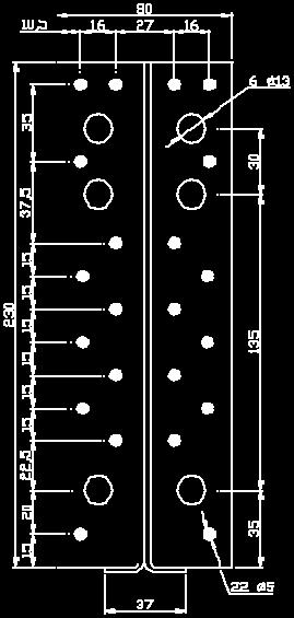
80 Page 0 of 113 of European Technical Assessment no. ETA-07/05, issued on -0- Figure D3-2: Nail pattern ETNM TYPE BEAM to BEAM BEAM to POST TYPE BEAM to BEAM BEAM to POST nails 2 dowels Ø 11 nails 2 dowels Ø 1 nails 5 dowels Ø2 nails 5 dowels Ø nails 2 dowels Ø nails 2 dowels Ø nails 3 dowels Ø 1 nails 3 dowels Ø
81 Page 1 of 113 of European Technical Assessment no. ETA-07/05, issued on -0- D4 Concealed joist hanger BTCx Product Name Branch alternative names Branch Branch BTCx Figure D4-1: Dimension drawing of concealed joist hangers Branch 47 BTCx C t B A A C = 96 Figure D4-2: Size specification cut-out may be possible ø A3 A2 A1 A ø13 3 n x
82 Page 2 of 113 of European Technical Assessment no. ETA-07/05, issued on -0- Table D4-1: Size specification all size in [mm] Type A A1 A2 A3 B C t Ømm anchor no of holes Ø13mm dowel BTC BTC BTC BTC BTC BTC BTC BTC BTC BTC BTC BTC BTC Table D4-2: Material specification Material Material Grades thickness Coating stecification 3 S 2 GD Z275 3 stainless steel as destriped For installation for fire justification, see clause B5 Table D4-3: Characteristic capacities R1.k and R2.k Characteristic capacity R 1,k and R 2.k [kn] b 3 SD 4 SD 5 SD 6 SD 7 SD SD 9 SD SD 11 SD SD 0 11,5 1,5,7 35, 45,6,0 66, 77,9 9,1 0,5 0,7,4 29,4 39,4,1 61,4 73,1 5,1 97,2 9,5 1,2,,7 43, 55,6 6,1 0,9 94,0 7,3 1,7 1 15, 25,3,4,6 61,7 75,5 9,6 4,1 11,7 133,4 1 17,2 27,,3 53, 6,3 3,4 99,0 1, 1,9 7,0 17,2 27,,3 54,3 69,4 5,5 2,2 119,5 133,3 7,0 b = min width [mm] of timber and length of the dowel The topmost steel dowel in the cut out hole shall not be considered for R 2.k The necessary capacity of the bolts should be calculated as: F1, d Rbolt, lat, d n For the upper bolts additional: F1, d,4 Rbolt, ax, d d With: R bolt,lat,d design capacity of one anchor bolt for shear load, but max.,0 kn R bolt,ax,d design capacity of one anchor bolt for tension load d height of the BTC -mm [mm] n number of anchor bolts
83 Page 3 of 113 of European Technical Assessment no. ETA-07/05, issued on -0- Table D4-4: Characteristic capacities R3.k It is assumed that the force F 3 is action at the top of the BTC. For a force F 3 with a lower distance to the middle of the BTC, the same capacities may be to use number of joist R3, k [kn] for b =.. [mm] without screws Type SD bolts b / h [mm] BTC / 1 2,6 2,9 3,5 4,0 4,5 5,2 5,3 BTC / 0 3,2 3,9 4,4 5,0 5,9 6,5 7,0 BTC / 0 4,0 4,9 5,5 6,3 7,2 7,, BTC / 0 4, 5,7 6,6 7,5,4 9,1,4 BTC / 3 5,6 6,5 7,6,7 9,6,4 11,9 BTC / 0 6,4 7,3,6 9,7, 11, 13,4 BTC / 0 7,2,1 9,5,,0 13,2,9 BTC0... / 0,0,9,5 11,9 13,2,7,4 BTC / 0, 9,7 11,4 13,0,4,1 17, BTC0... / 5 9,6,6,4,1 15,6 17,6 19,3 BTC5... / 5,4 11,4 13,3 15,1, 19,1, BTC5... / 0 11,2,3,3,2 1,0,5,3 BTC0... / 6,0 13,2 15,2 17,3 19,2,0 23, SD = steel dowel Table D4-5: Characteristic capacities R3.k with screws for reinforcement It is assumed that the force F 3 is action at the top of the BTC. For a force F 3 with a lower distance to the middle of the BTC, the same capacities may be to use number of joist R3, k [kn] for b =.. [mm] with screws * Type SD bolts b / h [mm] BTC / 1 2,6 2,9 4,4 5,3 5,3 5,3 5,3 BTC / 0 3,2 4,3 6,6 7,0 7,0 7,0 7,0 BTC / 0 4,0 5,5,6,,,, BTC / 0 4, 6,3,,6,6,6,6 BTC / 3 5,6 6, 9,6,3,3,3,3 BTC / 0 6,4 7,5,1,1,1,1,1 BTC / 0 7,2,1 11,0 15,2 15, 15, 15, BTC0... / 0,0,9 11,0 15,2 17,6 17,6 17,6 BTC / 0, 9,7,1,1 19,3 19,3 19,3 BTC0... / 5 9,6,6, 17,1 21,1 21,1 21,1 BTC5... / 5,4 11,4 13,3 17,1,9,9,9 BTC5... / 0 11,2,3,3 17,6,6,6,6 BTC0... / 6,0 13,2 15,2 1,,6,4,4 * see clause C.2 ~ Reinforcement with screws F 3 screw 6,0x L with L = b-mm (for timber with b=mm use screws 5,0x) number of screws = number of steel dowel
84 Page 4 of 113 of European Technical Assessment no. ETA-07/05, issued on -0- The connection of the bolts to the concrete must be check: The bolt group must be able to resist the min : F 3,d [kn] M Y,F3,d = F 3,d x mm [knmm] M X,F3,d = F 3d x (A/2) [knmm], with A = the height of the BTC [mm] F 3 M Y,F3 M X,F3 Table D4-6: Characteristic capacities F4.k no of R 3,k no of min bolts [kn] dowel 2 6,7/k mod 3 < F ,4/k mod 3 6,1/k mod 5 <,/k mod 6 The force is acting in the middle of the joist. The dowel and anchor bolts should be placed symmetrical to the centreline of the joist, and with a max distance of the anchor to the dowel of mm. It should be checked, that the capacity of bolt is: Where: R bolt,ax,d n b F 4,d R bolt, ax, d the axial design capacity of each anchor bolts / bolts the number of anchor bolts / bolts the design load in direction of the joist F 4, d 1, n b For combination it should be checked: F R 1or 2, d 1or 2, d 2 F R 3, d 3, d 2 F R 4, d 4, d F 1, d F2, d F3, d F4, d 1 R1, d R2, d R3, d R4, d By F 1 and F 2 has to be considered only one of both on one time. 2 The anchor bolts should be checked separately for the combination of load. 2
85 Page 5 of 113 of European Technical Assessment no. ETA-07/05, issued on -0- D5 ICS Product Name ICS Branch Alternative names Branch Branch Branch 47 Figure D5-1: Drawings Male Part Female Part Table D5-2: dimensions and number of fastener ICS A B C D E Thickness Holes Male Part Ø5 Female Part Ø5 Table D5-3: Material specification Material thickness Material Grades Coating specification 3 S 2 GD Z275 3 stainless steel as described For installation for fire justification, see clause B5 Table D5-4:Characteristic capacities : Characteristic capacities for single ICS and for timber grade C: ICS Characteristic Capacities C [kn] Fasteners Load direction Male part Female part Shear Withdrawal 6 screws CSA Ø5.0x35 6 screws CSA Ø5.0x (1) 3.4 (2) 4.17 (3) (1) Shear capacity is given for a displacement of 15 mm. (2) Shear capacity is given for a displacement of 5 mm (3) Withdrawal capacity is given for a displacement of 3 mm.
86 Page 6 of 113 of European Technical Assessment no. ETA-07/05, issued on -0- Shear Withdrawal 3 mm Timber element 1 d1 Timber element 2 Timber element 1 Timber element 2 F Lateral shear d1 Position of the ICS 3 mm Figure 1 : Timber element and position of ICS Figure 2 : Lateral shear tests Support of the 2 timber elements Support of the timber element n 1
87 Page 7 of 113 of European Technical Assessment no. ETA-07/05, issued on -0- Timber element 1 Timber element 2 Timber element 1 Timber element 2 F Lateral bending F withdrawal Support of the 2 timber elements Support of the 2 timber elements Support of the timber element n 2 Figure 3 : Lateral bending tests Figure 4 : Withdrawal tests 3 ICS Characteristic Capacities C [kn] Fasteners Load direction / configuration Male part Female part Lateral Shear Lateral Bending Withdrawal 3 x 6 screws CSA Ø5.0x35 3 x 6 screws CSA Ø5.0x35.3 (1) 13.3 (1) 6.31 (2) 4.02 (2) 5.57 (3) (1) Lateral capacity is given for a displacement of 15 mm. (2) Lateral capacity is given for a displacement of 5 mm (3) Withdrawal capacity is given for a displacement of 3 mm. For other timber grade with a lower density, the following k dens ratio should be applied: k dens 2 ) 3 ( k
88 Page of 113 of European Technical Assessment no. ETA-07/05, issued on -0- D6 ETB Product Name ETB Branch alternative names Branch Branch Branch 47 Figure D6-1: Drawings B H3 H2 H1 t1 male part ø5 B t2 H female part ETB90 ETB1 ETB1 ETB190 ETB2 partial nailing or screwing for column connections for fixing before screwing
89 Page 9 of 113 of European Technical Assessment no. ETA-07/05, issued on -0- Table D6-1: dimensions and number of fastener sizes [mm] n n Type H B H1 H2 H3 t1 / t2 Ø5,4 Ø5 ETB , / ETB , / ETB , / 6 11 ETB , / ETB , / 6 19 Table D6-2: Material specification Material Material Grades thickness [mm] 6 Aluminium EN AW-2 T6 according to EN stainless steel as described Coating specification For installation for fire justification, see clause B5 Table D6-3:Characteristic capacities : ETB connectors - Force downward R n min n 0,9 J H R 1, k 2 R lat, k ax,, k n J n H R lat,k R ax,α,k number of screws in the joist number of screws or nails in the side grain of the header or column Characteristic value of the load-carrying-capacity of a laterally loaded header/column nail or screw in single shear in a steel-to-timber connection with a thick steel plate according to EN or ETA 04/0013 in N characteristic axial load-carrying capacity of the screws in the joist according to EN :04:0+A1:0(E) in N, for the angle between the fiber of timber and the axis of the screw.
90 Page 90 of 113 of European Technical Assessment no. ETA-07/05, issued on -0- D7 EL Product Name EL xx xx = size of EL Branch alternative names Branch Branch Branch 47 Figure D7-1: Drawings 55 b= b= b= b= 0 b= partial screwing 35 Table D7-1: dimensions and number of fastener number of holes Ø5,4mm type 45 top EL 3 1 EL 6 1 EL 9 2 EL0 3 EL EL EL EL EL0 EL0 Table D7-2: Material specification Material Material Grades thickness 6 Aluminium EN AW-2 T6 according to EN stainless steel as described Coating specification For installation for fire justification, see clause B5
91 Page 91 of 113 of European Technical Assessment no. ETA-07/05, issued on -0- Table D7-3:Characteristic capacities : R 1, k 0,9 nj R 2 kc,90 f c min A 27 b kmod ax,, k,90ck A ef b 11,25 k 25 f c,90 f y, k c,90, k A A ef 30 R 4, k 0,3 F min nh R 1, d lat, k n J n H number of screws in the joist number of screws in the upper surface of the header k c,90 Factor according to EN :A1 taking into account the load configuration, the possibility of splitting and the degree of compressive deformation f c,90,k A ef A b f y,k F 1,d R ax,α,k R lat,k Characteristic compressive strength perpendicular to the grain in N/mm² Effective contact area perpendicular to the grain in mm² according to EN :A1 Actual contact area perpendicular to the grain in mm² Width of the SIMPSON STRONG-TIE EL hanger in mm Aluminium minimum yield strength in N/mm²; f y,k = 2 N/mm² design value of the joist support load perpendicular to the joist axis in N characteristic axial load-carrying capacity of the screws in the joist according to EN :04:0+A1:0(E) in N, for the angle between the fiber of timber and the axis of the screw. Characteristic value of the load-carrying-capacity of a laterally loaded header nail or screw in N
92 Page 92 of 113 of European Technical Assessment no. ETA-07/05, issued on -0- F 2 uplift force R ax An uplift force may be adsorbed by an extra screw as shown above. R 2, k R ax, k ( Screw) 2 Rax,k(Screw) characteristic axial load-carrying capacity of the extra screw as the min of threaded part and pull through capacity of the head.
93 Page 93 of 113 of European Technical Assessment no. ETA-07/05, issued on -0- D ELS Product Name ELS xx xx = size of ELS Branch alternative names Branch Branch Branch 47 Figure D-1: Drawings 0 b= b= b= b= 0 b= x partial screwing Table D-1: dimensions and number of fastener number of holes Ø5,4 Ø5,0 type 45 top ELS 3 5 ELS 6 ELS 9 13 ELS0 15 ELS Table D-2: Material specification Material Material Grades thickness Aluminium EN AW-2 T6 according to EN stainless steel as described Coating specification For installation for fire justification, see clause B5 Table D-3:Characteristic capacities : R n min n 0,9 J Rax,, k 1, k 2 H R lat, k
94 Page 94 of 113 of European Technical Assessment no. ETA-07/05, issued on -0- n J n H R ax,α,k R lat,k number of screws in the joist number of screws in the upper surface of the header characteristic axial load-carrying capacity of the screws in the joist according to EN :04:0+A1:0(E) For a connection with a slope < 0, it shall be check the permission for angle between the fiber of timber and the axis of the screw. Characteristic value of the load-carrying-capacity of a laterally loaded header nail or screw in N F 2 uplift force R ax An uplift force may be adsorbed by an extra screw as shown above. R 2, k R ax, k ( Screw) 2 Rax,k characteristic axial load-carrying capacity of the extra screw as the min of threaded part and pull through capacity of the head.

95 Page 95 of 113 of European Technical Assessment no. ETA-07/05, issued on -0- D9 CBH Product Name CBH xxx / 2.5 xxx = size of CBH Branch alternative names Branch Branch Branch 47 Figure D9-1: Drawings Table D9-1: dimensions and number of fastener Model Width W Height H Depth D Angle [mm] degree Direction CBH1/2, ,5 90 ~ CBH/2,5 113,5 90 ~ CBH2/2, ,5 90 ~ Model Header Fasteners nails or screws * Bolts Anchors Wood screws Joist Fasteners Dowel Ø acc. To EN 592 CBH1/2,5 2-Ø 5 CBH/2,5 2-Ø 6 CBH2/2,5 2-Ø 7 * According to ETA 04/0013 or according to EN592 Washer for a wood/ rigid support connection. The minimum dimension have to be used: - Bolt Ø + Washer M (Øext = Øint = 11mm)
96 Page 96 of 113 of European Technical Assessment no. ETA-07/05, issued on -0- Table D9-2: Material specification Material Material Grades thickness Coating specification 3 S 2 GD Z275 3 stainless steel as described For installation for fire justification, see clause B5 Table D9-3:Characteristic capacities R1.k [kn] timber to timber: Characteristic value [kn] of a CBH concealed Joist hangers for connections between timber header beam and timber supported joist. Widths Slope 0 5 CBH1 1,0 1,6,7,4,0,0 17, 1,4,3,0 23, 23, 17,5 1,1,0 21,6 23,4 23,5 CBH 25,0,4 29,5,1,6,6,7,1 29,1 31,6,4,4,3 25,6,5 31,0,1,1 CBH2,6 34,2 37,9 41,1 42, 42,,2 33,7 37,3,4 42,4 42,4 31, 33,2,6 39,7 42,0 42,0 Widths Slope CBH1 17,3 17,9 19,6 21,2,9 23,3 17,1 17,6 19,3,,4 23,0,9 17,4 19,0,4,0,7 CBH,0 25,2,0,5 31, 31, 23,6, 27,5 29,9 31,4 31,4 23,4,5 27,0 29,3 31,1 31,1 CBH2 31,4,7 35,9 3,9 41,6 41,6 31,0,3 35,3 3,2 41,1 41,1,7 31, 34, 37,5,4,7 Widths Slope 35 CBH1,7 17,2 1,7,1 21,6,5,6 17,0 1,4 19, 21,2,3,5, 1,2 19,5,9,1 CBH 23,1,1,6,,,, 23,,2,4,5,5,7 23,6 25,9,0,1,3 CBH2,4 31,5 34,3 37,0 39,7,4,1 31,2 33,9,5 39,1,0,0 31,0 33,6,1 3,7 39, Widths Slope 45 CBH1,3,7 1,0 19,3,6 21,9 CBH,5 23,4 25,6 27,6 29,7,1 CBH2 29,, 33,3 35,7 3,3 39,5
97 Page 97 of 113 of European Technical Assessment no. ETA-07/05, issued on -0- Table D9-4:Characteristic capacities R1.k [kn] timber to steel/concrete: Characteristic values [kn] for connection where the CBH joist hanger is bolted to a steel or reinforced concrete structural member and carrying a timber supported joist. 1. Dowel characteristic capacity Fk,dowels Widths Slope 0 5 CBH1,4 13,2 15,6 17,7 19,5 19,5,2 13,0 15,2 17,3 19,3 19,3,0,7,9,9 19,0 19,0 CBH 19,3 21,1 25,2, 29,7 29,7 1,9,7,6,1 29,2 29,2 1,5,2 23,9 27,4,, CBH2 23, 25,9,6 34,9 37,1 37,1 23,4 25,4 29, 34,0,6,6,9, 29,0 33,0,0,0 Widths Slope CBH1 11,7,4,5,4 1,4 1,7 11,5,1,1 15,9 17,9 1,3 11,3 11, 13,7 15,4 17,3 1,0 CBH 1,2 19,7 23,3,6,3,3 17, 19,2,6 25, 27, 27, 17,4 1,,0 25,0 27,3 27,3 CBH2,4,2,2,1 35,3 35,3,0 23,6 27,4 31,1 34,7 34,7 21,5 23,0,7,2 34,0 34,1 Widths Slope 35 CBH1 11,0 11,6 13,4 15,0, 17,7, 11,3 13,0,6,3 17,4,7 11,1,7,2 15,9 17,1 CBH 17,0 1,3 21,4,3,,,7 17,9,9 23,6,4,4,4 17,6,4 23,1,0,0 CBH2 21,1,5,0 29,4 33,0 33,5,7,1 25,4,6,2 33,0,4 21,7,9,0 31,4,6 Widths Slope 45 CBH1,5,9,5 13,9 15,5,9 CBH,2 17,3,0,6 25,4 25,7 CBH2,1 21,3,4 27,4,,2 2. Max characteristic capacity [kn] of the steel part Fk,steel Model Fk,steel CBH1 15,9 CBH 23,3 CBH2,1 3. Design capacity of the CBH F d,cbh Fk, Fd, CBH min Fk, dowels steel M k M mod
98 Page 9 of 113 of European Technical Assessment no. ETA-07/05, issued on -0- D ETS Product Name ETS Branch alternative names Branch Branch Branch 47 Figure D-1: Drawings Each ETS is made using two parts: ETS1 = ETS1/1-C + ETS1/2-C to joist B A C to header ETS0/1-C ETS0/2-C B B A t A t
99 Page 99 of 113 of European Technical Assessment no. ETA-07/05, issued on -0- ETS1 = ETS1/1-C + ETS1/2-C B B B A C ETS1/1-C ETS1/2-C A t A t ETS = ETS/1-C + ETS/2-C B A C ETS/1-C ETS/2-C B B ETSxxx/1-C is for the joist ETSxxx/2-C is for the header A t A t Table D-1: dimensions and number of fastener
100 Page 0 of 113 of European Technical Assessment no. ETA-07/05, issued on -0- Model ETS0 ETS0/1 C ETS0/2 C ETS1 ETS1/1 C ETS1/2 C ETS ETS/1 C ETS/2 C Dimensions A (mm) B (mm) C (mm) t (mm) SPAX screws 5.0x Fasteners CSA5.0x Table D-2: Material specification Material thickness Material Grades [mm] Pre-galvanized steel Grade S2GD + Z (min Z275) according to EN 3 with tolerances according to EN 3 except if another material is specified. Or Stainless steel number 1.01 or number 1.04 according to EN 0-2 with a minimum 3 characteristic 0.2% yield stress of 0 MPa, a minimum 1.0% yield stress of 270 MPa and a minimum ultimate tensile strength of 5 MPa or a stainless steel with a minimum characteristic 0.2% yield stress of 0 MPa, a minimum 1.0% yield stress of 270 MPa and a minimum ultimate tensile strength of 5 MPa. If ETS are made using Stainless Steel, stainless fasteners need to be used. For installation for fire justification, see clause B5
101 Page 1 of 113 of European Technical Assessment no. ETA-07/05, issued on -0- Table D-3:Characteristic capacities : ETS connectors - Force downward R n min n 0,9 J H R 1, k 2 R lat, k ax,, k n J n H R lat,k R ax,α,k number of screws at 45 in the joist number of screws in the side grain of the header Characteristic value of the load-carrying-capacity of a laterally loaded header/column nail or screw in single shear in a steel-to-timber connection with a thick steel plate according to EN or ETA 04/0013 in N characteristic axial load-carrying capacity of the screws in the joist according to EN :04:0+A1:0(E) in N, for the angle between the fiber of timber and the axis of the screw.
102 Page 2 of 113 of European Technical Assessment no. ETA-07/05, issued on -0- D11 ICST Product Name ICST alternative names UK France DK D Figure D11-1: Drawings A-A 0 A A ~6 2 ~7 15 ø5 rib ~. For a connection 2 single pieces have to be use as a pair Table D11-1: Size specification Dimensions Number of Fasteners A B C D Supporting Member Supported Member The ICST consists of two single pieces sharp corner D or rounded corner C B A Table D11-2: Material specification Material thickness Material Grades Coating specification S2 GD according to EN 2 6:04 Or stainless steel according to clause II-1 For installation for fire justification, see clause B5 Z275 according to EN6:04
103 Page 3 of 113 of European Technical Assessment no. ETA-07/05, issued on -0- Figure D11-2: Nail/screw pattern Full nailing e.g. CNA 4,0xl nails, CSA5,0xl screws Table D11-3: Characteristic capacity [kn] characteristic capacities [kn] per connection (one pair) For one pair of ICST = two single pieces min of: R 3,k R 4,k 6,72*R lat,k min of: 4 x R ax,k,9/k mod 5,35/k mod With R lat,k = the lateral capacity of one single used fastener R ax,k = the axial capacity of one single used fastener For connection between timber elements (e.g. two wall elements) multiple ICST may be used. F4 F3 The two single pieces are to place on the same high (for example same distance a from the top as described below), by the mounting the elements are to fit into each other a a 2
104 Page 4 of 113 of European Technical Assessment no. ETA-07/05, issued on -0- D Janebo : JHHU, JHDU, JHGU Product Name JHHxx JHD1 xx alternative names UK France DK D JHHUxx JHDUxx JHGUxx Types with the U are for products with steel dowel for uplift; Drawings B h1 t1=mm optional steel dowel ø A Figure D-1: Dimensioned drawings of JHHU C B 3 A h2 h1 25 ø5 ø optional steel dowel t1 t2 Figure D-2: Dimensioned drawings of JHDU

105 Page 5 of 113 of European Technical Assessment no. ETA-07/05, issued on -0- B 63 A 25 n x ø13 t1=mm 15 h2 optional steel dowel Figure D-3: Dimensioned drawings for JHGU JHHU and JHDU option for the hook JHH and JHD steel dowel Ømm for uplift 25 ø13 Figure D-4: The hook for all types can be made in two different version, for an uplift force only the left one can be use. Figure D-5: example of use, for an uplift force (F 2 ) the steel dowel as shown in figure D-4 on the left one has to be installed
European Technical Assessment ETA-17/1005 of
 ETA-Danmark A/S Göteborg Plads 1 DK-2150 Nordhavn Tel. +45 72 24 59 00 Fax +45 72 24 59 04 Internet www.etadanmark.dk Authorised and notified according to Article 29 of the Regulation (EU) No 305/2011
European Technical Approval ETA-07/0212
 ETA-Danmark A/S Kollegievej 6 DK-2920 Charlottenlund Tel. +45 45 76 20 20 Fax +45 45 76 33 20 Internet www.etadanmark.dk Authorised and notified according to Article 10 of the Council Directive 89/106/EEC
European Technical Assessment ETA-13/0029 of 11/07/2017
 ETA-Danmark A/S Göteborg Plads 1 DK-2150 Nordhavn Tel. +45 72 24 59 00 Fax +45 72 24 59 04 Internet www.etadanmark.dk Authorised and notified according to Article 29 of the Regulation (EU) No 305/2011
European Technical Approval ETA-10/0038
 ETA-Danmark A/S Kollegievej 6 DK-2920 Charlottenlund Tel. +45 72 24 59 00 Fax +45 72 24 59 04 Internet www.etadanmark.dk Authorised and notified according to Article 10 of the Council Directive 89/106/EEC
European Technical Approval ETA-08/0165
 ETA-Danmark A/S Kollegievej 6 DK-2920 Charlottenlund Tel. +45 72 24 59 00 Fax +45 72 24 59 04 Internet www.etadanmark.dk Authorised and notified according to Article 10 of the Council Directive 89/106/EEC
European Technical Approval ETA-08/0007
 ETA-Danmark A/S Kollegievej 6 DK-2920 Charlottenlund Tel. +45 72 24 59 00 Fax +45 72 24 59 04 Internet www.etadanmark.dk Authorised and notified according to Article 10 of the Council Directive 89/106/EEC
European Technical Approval ETA-08/0183
 ETA-Danmark A/S Kollegievej 6 DK-2920 Charlottenlund Tel. +45 72 24 59 00 Fax +45 72 24 59 04 Internet www.etadanmark.dk Authorised and notified according to Article 10 of the Council Directive 89/106/EEC
European Technical Approval ETA-13/0630
 ETA-Danmark A/S Kollegievej 6 DK-2920 Charlottenlund Tel. +45 72 24 59 00 Fax +45 72 24 59 04 Internet www.etadanmark.dk Authorised and notified according to Article 10 of the Council Directive 89/106/EEC
Verbindungselemente Engel GmbH Weltestraße Weingarten DEUTSCHLAND. Manufacturing plant 74437, , ,
 European Technical Assessment ETA-13/0536 of 20 February 2018 - Original version in German language General Part Technical Assessment Body issuing the European Technical Assessment: Trade name of the construction
European Technical Approval ETA-10/0413
 ETA-Danmark A/S Kollegievej 6 DK-2920 Charlottenlund Tel. +45 72 24 59 00 Fax +45 72 24 59 04 Internet www.etadanmark.dk Authorised and notified according to Article 10 of the Council Directive 89/106/EEC
European Technical Assessment ETA-11/0024 of 02/03/2017
 ETA-Danmark A/S Göteborg Plads 1 DK-2150 Nordhavn Tel. +45 72 24 59 00 Fax +45 72 24 59 04 Internet www.etadanmark.dk Authorised and notified according to Article 29 of the Regulation (EU) No 305/2011
European Technical Assessment ETA-12/0197 of 12/07/2017
 ETA-Danmark A/S Göteborg Plads 1 DK-2150 Nordhavn Tel. +45 72 24 59 00 Fax +45 72 24 59 04 Internet www.etadanmark.dk Authorised and notified according to Article 29 of the Regulation (EU) No 305/2011
European Technical Assessment ETA-11/0024 of 08/07/2016
 ETA-Danmark A/S Göteborg Plads 1 DK-2150 Nordhavn Tel. +45 72 24 59 00 Fax +45 72 24 59 04 Internet www.etadanmark.dk Authorised and notified according to Article 29 of the Regulation (EU) No 305/2011
European Technical Assessment. ETA-15/0667 of Member of. General part
 INSTITU Schenkenstrasse 4 T +43 1 533 65 50 1010 Vienna Ι Austria F +43 1 533 64 23 www.oib.or.at Ι mail@oib.or.at Designated according to Article 29 of Regulation (EU) No 305/2011 Member of www.eota.eu
European Technical Assessment. ETA-14/0426 of 15 December English translation prepared by DIBt - Original version in German language
 European Technical Assessment ETA-14/0426 of 15 December 2014 - Original version in German language General Part Technical Assessment Body issuing the European Technical Assessment: Trade name of the construction
European Technical Assessment. ETA-14/0426 of 21 December English translation prepared by DIBt - Original version in German language
 European Technical Assessment ETA-14/0426 of 21 December 2016 - Original version in German language General Part Technical Assessment Body issuing the European Technical Assessment: Trade name of the construction
(English language translation, the original version is in French language) Simpson Strong-Tie. Universal brackets Purlin anchors Joist anchors
 Simpson Strong-Tie. Universal brackets Purlin anchors Joist anchors") Page 1 technical Approval Centre Scientifique et Technique du Bâtiment 84 avenue Jean Jaurès CHAMPS-SUR-MARNE F-77447 Marne-la-Vallée Cedex 2 Tél. : (33) 01 64 68 82 82 Fax : (33) 01 60 05 70 37 Autorisé
Page 1 technical Approval Centre Scientifique et Technique du Bâtiment 84 avenue Jean Jaurès CHAMPS-SUR-MARNE F-77447 Marne-la-Vallée Cedex 2 Tél. : (33) 01 64 68 82 82 Fax : (33) 01 60 05 70 37 Autorisé
Powers Trak-It XH and HD nails for gas actuated tools C4 and C5
 European Technical Assessment ETA-12/0188 of 7 October 2016 - Original version in German language General Part Technical Assessment Body issuing the European Technical Assessment: Trade name of the construction
STRUCTURAL TIMBER DESIGN
 STRUCTURAL TIMBER DESIGN to Eurocode 5 2nd Edition Jack Porteous BSc, MSc, DIC, PhD, CEng, MIStructE, FICE Director lack Porteous Consultancy and Abdy Kernlani BSc, MSc, PhD, CEng, FIStructE, FIWSc Professor
European Technical Approval ETA-12/0114
 ETA-Danmark A/S Kollegievej 6 DK-2920 Charlottenlund Tel. +45 72 24 59 00 Fax +45 72 24 59 04 Internet www.etadanmark.dk Authorised and notified according to Article 10 of the Council Directive 89/106/EEC
European Technical Assessment ETA 15/0029 of 12/06/2017
 RISE Research Institutes of Sweden AB RISE Certifiering Box 553 SE-371 23 Karlskrona Sweden Member of www.eota.eu Tel: +46 10 516 63 00 Web: www.ri.se Mail: certifiering@ri.se European of 12/06/2017 General
European Technical Assessment. ETA-16/0902 of 17 March English translation prepared by DIBt - Original version in German language.
 European Technical Assessment ETA-16/0902 of 17 March 2017 - Original version in German language General Part Technical Assessment Body issuing the European Technical Assessment: Trade name of the construction
DICHIARAZIONE DI PRESTAZIONE ai sensi del regolamento sui prodotti da costruzione (EU) N 305/2011 N : LE_13_0026_IT
 N 305/2011 N : LE_13_0026_IT") DICHIARAZIONE DI PRESTAZIONE ai sensi del regolamento sui prodotti da costruzione (EU) N 305/2011 N : LE_13_0026_IT 1. Codice univoco di identificazione del tipo di prodotto 2. Numero di tipo, lotto, serie
DICHIARAZIONE DI PRESTAZIONE ai sensi del regolamento sui prodotti da costruzione (EU) N 305/2011 N : LE_13_0026_IT 1. Codice univoco di identificazione del tipo di prodotto 2. Numero di tipo, lotto, serie
Österreichisches Institut für Bautechnik Schenkenstrasse Vienna Austria T F
 Authorised and notified according to Article 10 of the Council Directive 89/106/EEC of 21 December 1988 on the approximation of laws, regulations and administrative provisions of Member States relating
Dowel-type fasteners. Timber Connections. Academic resources. Introduction. Deferent types of dowel-type fasteners. Version 1
 Academic resources Timber Connections Dowel-type fasteners Version 1 This unit covers the following topics: Deferent types of dowel-type fasteners Introduction There are four criteria designers should
ALUMIDI. Concealed beam hanger with and without holes Aluminum alloy tridimensional perforated plate ALUMIDI - 01 CERTIFIED STEEL-ALUMINUM
 ALUMIDI Concealed beam hanger with and without holes Aluminum alloy tridimensional perforated plate CERTIFIED Available with and without holes. The 2200 mm model is also certified FIELD OF USE Timber-to-Timber
LOAD CARRYING CAPACITY OF METAL DOWEL TYPE CONNECTIONS OF TIMBER STRUCTURES
 Vol. 10, Issue /014, 51-60 DOI: 10.478/cee-014-0011 LOAD CARRYING CAPACITY OF METAL DOWEL TYPE CONNECTIONS OF TIMBER STRUCTURES Jozef GOCÁL 1,* 1 Department of Structures and Bridges, Faculty of Civil
European Technical Assessment. ETA-12/0373 of Member of. General part
 INSTITU Schenkenstrasse 4 T +43 1 533 65 50 1010 Vienna Ι Austria F +43 1 533 64 23 www.oib.or.at Ι mail@oib.or.at Designated according to Article 29 of Regulation (EU) No 305/2011 Member of www.eota.eu
European Technical Approval ETA-11/0024
 ETA-Danmark A/S Kollegievej 6 DK-2920 Charlottenlund Tel. +45 72 24 59 00 Fax +45 72 24 59 04 Internet www.etadanmark.dk Authorised and notified according to Article 10 of the Council Directive 89/106/EEC
European Technical Assessment. ETA-12/0056 of General Part. Technical Assessment Body issuing the ETA:
 Member of SINTEF Building and Infrastructure P.O.Box 124 Blindern NO-0314 Oslo, Norway Phone +47 40 00 51 00 e-mail: certification@sintef.no www.eota.eu European Technical Assessment ETA-12/0056 of 2018-12-15
Tensile strength of ASSY plus VG screws wood-wood (softwood)
") Tensile strength of ASSY plus VG screws wood-wood (softwood) STRENGTHENS THE WOOD - INSTEAD OF SPLITTING IT 23.05.2017 Table of contents for tensile strength Determining the tensile strength - Table values
Tensile strength of ASSY plus VG screws wood-wood (softwood) STRENGTHENS THE WOOD - INSTEAD OF SPLITTING IT 23.05.2017 Table of contents for tensile strength Determining the tensile strength - Table values
REISSER-Schraubentechnik GmbH Fritz-Müller-Straße Ingelfingen-Criesbach DEUTSCHLAND
 European Technical Assessment ETA-11/0106 of 20 June 2016 - Original version in German language General Part Technical Assessment Body issuing the European Technical Assessment: Trade name of the construction
CLT Cross Laminated Timber
 CLT Cross Laminated Timber Connections Date: 21.08.2014 Disclaimer The below presented structural analysis is an exemplified calculation. This calculation is solely a proposal for a design approach. This
Fosroc International Limited Drayton Manor Business Park Coles Road TAMWORTH STAFFORDSHIRE; B78 3XN GROSSBRITANNIEN EAD
 European Technical Assessment ETA-18/0586 of 12 July 2018 - Original version in German language General Part Technical Assessment Body issuing the European Technical Assessment: Trade name of the construction
SECTION R507 DECKS DECKING LEDGER BOARD BEAM. FOOTING BEAM SPAN CANTILEVER For SI: 1 inch = 25.4 mm FIGURE R507.2 DECK CONSTRUCTION
 SECTION R507 DECKS R507.1 Application. The provisions of this section shall provide prescriptive requirements for the design and construction of all uncovered, wood-framed, single-span exterior decks.
Klaus-Fischer-Straße Waldachtal DEUTSCHLAND EAD This version replaces ETA-07/0025 issued on 14 May 2018
 European Technical Assessment ETA-07/0025 of 28 August 2018 - Original version in German language General Part Technical Assessment Body issuing the European Technical Assessment: Trade name of the construction
ICC-ES Evaluation Report
 ICC-ES Evaluation Report ESR-6 Reissued April, 009 This report is subject to re-examination in two years. www.icc-es.org (800) 4-6587 (56) 699-054 A Subsidiary of the International Code Council DIVISION:
UV-T Concealed hook connector TIMBER - TIMBER Aluminum three dimensional perforated plate
 Concealed hook connector TIMER - TIMER Aluminum three dimensional perforated plate COMPLETE RANGE Available in 5 versions, to work with the secondary and load applied. Resistance over 60 kn FIELD OF USE
European Technical Assessment ETA-04/0101 English translation prepared by DIBt. Page 2 of 12 1 March 2018
 European Technical Assessment ETA-04/0101 Page 2 of 12 1 March 2018 The European Technical Assessment is issued by the Technical Assessment Body in its official language. Translations of this European
24" max from each end of the ledger. See detail 6A & 6B, typ. both ends IRC R Ledger R507.2
 NOTE: All exposed lumber to be pressure treated (P.T.) or decay resistant. Fasteners for P.T. wood shall be hot-dipped galv. or stainless steel, typical. see pages 2 & 5 for footings 8'-0" -10'-0" Beam
CONCEALED HOOK CONNECTORS UV-T / UV-C
 CONCEALED OOK CONNECTORS / UV-C GEOMETRY Choice of connection system according to the secondary joist cross section SECONDARY JOIST [] SECONDARY JOIST DEPT [] 300 250 200 150 100 50 0 0 200 400 600 800
Statement for nail plate LL13 Combi
 STATEMENT NO VTT-S-0369-17 1 (5) Request by Order Contact person Ristek Oy Askonkatu 11 FI-15110 Lahti 15.3.017 Kimmo Köntti VTT Expert Services Ltd Ari Kevarinmäki P.O. Box 1001, FI-0044 VTT Tel. +358
ESR-2648 Reissued May 1, 2012 This report is subject to renewal June 1, 2013.
 ICC-ES Evaluation Report ESR-2648 Reissued May 1, 2012 This report is subject to renewal June 1, 2013. www.icc-es.org (800) 423-6587 (562) 699-0543 A Subsidiary of the International Code Council DIVISION:
Glued laminated timber beams repair.
 Glued laminated timber beams repair. Master s Degree Extended Abstract Ricardo Cardoso Henriques da Silva Keywords: glulam, delamination, self-tapping screw, plywood, repair November 2014 1. INTRODUCTION
Glulam Connection Details
 T E C H N I C A L N O T E Glulam Connection Details Note: This version is superseded by a more current edition. Check the current edition for updated design and application recommendations. ENGINEERED
Load Tables, Technical Data and Installation Instructions
 W22. W22. W22. W22. W22 W22.. Simpson Strong-Tie Fastening Systems Structural Wood-to-Wood Connections Including Ledgers Designed to provide an easy-to-install, high-strength alternative to through-bolting
SDWH TIMBER-HEX Screw
 Simpson Strong-Tie Fastening Systems Structural Wood-to-Wood Connections, Including Ledgers Double-barrier coating provides corrosion resistance equivalent to hot-dip galvanization, making it suitable
Attachment of Residential Deck Ledger to Metal Plate Connected Wood Truss Floor Systems Overview Revised 9/2/2016
 Attachment of Residential Deck Ledger to Metal Plate Connected Wood Truss Floor Systems Overview Revised 9/2/2016 SBCA has been the voice of the structural building components industry since 1983, providing
European Technical Assessment. ETA-18/0861 of 12 November English translation prepared by DIBt - Original version in German language
 European Technical Assessment ETA-18/0861 of 12 November 2018 - Original version in German language General Part Technical Assessment Body issuing the European Technical Assessment: Trade name of the construction
Butt Two pieces of wood meeting with flat sides adjoining usually at right angles. Some type of connector is needed to prevent movement.
 Wood Connections There are basically five different types of connectors: Interlocking (carpentry joints), Dowel, Metal Connectors, Special Formed Connectors and Adhesives. I Interlocking (Carpentry Joints)
3.1 General Provisions
 WOOD FRAME CONSTRUCTION MANUAL 107 3.1 General Provisions 3.1.1 Prescriptive Requirements The provisions of this Chapter establish a specific set of resistance requirements for buildings meeting the scope
European Technical ETA-17/0513 Assessment of 27 October 2017 General Part
 European Technical Assessment ETA-17/0513 of 27 October 2017 - Original version in German language General Part Technical Assessment Body issuing the European Technical Assessment: Trade name of the construction
European Technical Assessment ETA-04/0038 English translation prepared by DIBt. Page 2 of July 2016
 European Technical Assessment ETA-04/0038 Page 2 of 15 29 July 2016 The European Technical Assessment is issued by the Technical Assessment Body in its official language. Translations of this European
concrete Apolo MEA Befestigungssysteme GmbH Industriestraße Aichach DEUTSCHLAND Apolo MEA Befestigungssysteme GmbH, Plant2 Germany
 European Technical Assessment ETA-09/0373 of 1 June 2018 - Original version in German language General Part Technical Assessment Body issuing the European Technical Assessment: Trade name of the construction
European Technical Assessment. ETA-18/0045 of 22 February English translation prepared by DIBt - Original version in German language
 European Technical Assessment ETA-18/0045 of 22 February 2018 - Original version in German language General Part Technical Assessment Body issuing the European Technical Assessment: Deutsches Institut
European Technical Assessment. ETA-08/0285 of General Part. Technical Assessment Body issuing the ETA:
 Member of SINTEF Building and Infrastructure P.O.Box 124 Blindern N-0314 Oslo Tel. 47 22 96 55 55 Fax 47 22 69 54 38TAB www.eota.eu European Technical Assessment ETA-08/0285 of 07.03.2014 General Part
A Shell construction
 A Shell construction A 4/2012 Content 1 BASE AND WALL ANCHORING 1.1 Base with mortar bed 1.2 Base with sill plate 1.3 Base with raised sill plate 1.4 Concrete base (mortar bed) 1.5 Concrete base (sill
European Technical ETA-13/1038 Assessment of 26 January 2018 General Part
 European Technical Assessment ETA-13/1038 of 26 January 2018 - Original version in German language General Part Technical Assessment Body issuing the European Technical Assessment: Trade name of the construction
ICC-ES Evaluation Report
 ICC-ES Evaluation Report www.icc-es.org (800) 423-6587 (562) 699-0543 ESR-2608 Reissued January 2016 This report is subject to renewal January 2017. A Subsidiary of the International Code Council DIVISION:
THE ENGINEERED WOOD ASSOCIATION
 D A T A F I L E APA Performance Rated Rim Boards A rim board is the wood component that fills the space between the sill plate and bottom plate of a wall or, in second floor construction, between the top
Beam & Header Technical Guide. LP SolidStart LVL. 2900F b -2.0E. U.S. Technical Guide U.S. TECHNICAL GUIDE
 U.S. Technical Guide U.S. TECHNICAL GUIDE LP SolidStart LVL & Header Technical Guide 2900F b -2.0E Please verify availability with the LP SolidStart Engineered Wood Products distributor in your area prior
Attach Trusses and Rafters Faster
 Attach Trusses and Rafters Faster SDWC TRUSS Screw Truss-to-Plate Connections For Truss-to-Plate Connections The Strong-Drive SDWC TRUSS screw provides a truss- and rafter-to-top-plate connection. The
BauBuche Fasteners and connections
 BauBuche Fasteners and connections Beech laminated veneer lumber Chapter under revision 05 BauBuche Fasteners and connections 05 04-18 - EN Sheet 1 / 10 Fasteners and connections Sheet CONTENTS 2 3 4 9
DIVISION: WOOD, PLASTICS AND COMPOSITES SECTION: WOOD, PLASTIC, AND COMPOSITE FASTENINGS REPORT HOLDER:
 0 Most Widely Accepted and Trusted ICC ES Evaluation Report ICC ES 000 (800) 87 () 99 0 www.icc es.org ESR 9 Reissued 0/08 This report is subject to renewal 0/09. DIVISION: 0 00 00 WOOD, PLASTICS AND COMPOSITES
European Technical Approval ETA-11/0283
 European Technical Approval ETA-11/0283 - Original version in German language Handelsbezeichnung Trade name Zulassungsinhaber Holder of approval Zulassungsgegenstand und Verwendungszweck Generic type and
Designed for Building Designed for Living
 Designed for Building Designed for iving decorative hardware Add Beauty and Strength to Your Custom Outdoor iving Structures ith Outdoor Accents, a new line of decorative timber connectors and fasteners
Klaus-Fischer-Straße Waldachtal DEUTSCHLAND EAD This version replaces ETA-15/0352 issued on 12 April 2016
 European Technical Assessment ETA-15/0352 of 30 October 2018 - Original version in German language General Part Technical Assessment Body issuing the European Technical Assessment: Trade name of the construction
APA Performance Rated Rim Boards
 D a t a F i l e APA Performance Rated Rim Boards A Rim Board is the wood component that fills the space between the sill plate and bottom plate of a wall or, in second floor construction, between the top
Introducing AJSTM INSTALLATION GUIDE USA. 8 th Edition USA
 The SIMPLE FRAMING SYSTEMSM INSTALLATION GUIDE USA for Floors This Installation Guide is intended to provide general information for the designer and end-user. For further information, please refer to
(English language translation, the original version is in French language) fischer Anchor bolt EXA
 fischer Anchor bolt EXA") Centre Scientifique et Technique du Bâtiment 84, avenue Jean Jaurès CHAMPS SUR MARNE F-77447 Marne-la-Vallée Cedex 2 Tél. : (33) 01 64 68 82 82 Fax : (33) 01 60 05 70 37 Autorisé et notifié conformément
Centre Scientifique et Technique du Bâtiment 84, avenue Jean Jaurès CHAMPS SUR MARNE F-77447 Marne-la-Vallée Cedex 2 Tél. : (33) 01 64 68 82 82 Fax : (33) 01 60 05 70 37 Autorisé et notifié conformément
European Technical Approval ETA-10/0182
 European Technical Approval English translation prepared by DIBt - Original version in German language Handelsbezeichnung Trade name Zulassungsinhaber Holder of approval Zulassungsgegenstand und Verwendungszweck
VERSA-LAM. An Introduction to VERSA-LAM Products
 44 VERSA-LAM An Introduction to VERSA-LAM Products VERSA-LAM is one of the strongest and stiffest engineered wood products approved in the UK. 241 302 356 406 VERSA-LAM products are excellent as floor
ANCHORING TECHNOLOGY CAST-IN CHANNELS PEC-TA
 ANCHORING TECHNOLOGY CAST-IN CHANNELS PEC-TA European Technical Assessment ETA-16/0929 European Technical Assessment ETA-16/0929 of 9 August 2018 - Original version in German language General Part Technical
DIVISION: WOOD, PLASTICS AND COMPOSITES SECTION: WOOD, PLASTIC, AND COMPOSITE FASTENINGS REPORT HOLDER:
 0 Most Widely Accepted and Trusted ICC ES Evaluation Report ICC ES 000 (800) 423 6587 (562) 699 0543 www.icc es.org ESR 2761 Reissued 10/2017 This report is subject to renewal 10/2019. DIVISION: 06 00
Featuring TJ Rim Board and TimberStrand LSL
 #TJ-8000 SPECIFIER S GUIDE TRUS JOIST RIM BOARD Featuring TJ Rim Board and TimberStrand LSL Multiple thicknesses, grades, and products to cover all your rim board needs 1¼" Thickness matches lateral load
T-BRACE / I-BRACE DETAIL WITH 2X BRACE ONLY
 August 10, 2010 T-BRACE / I-BRACE DETAIL WITH 2X BRACE ONLY ST - T-BRACE 2 R MiTek Industries, Chesterfield, MO Page 1 of 1 Note: T-Bracing / I-Bracing to be used when continuous lateral bracing is impractical.
LVL8 H1.2 GENERAL FRAMING. Eco Friendly Revolutionary H1.2 Treatment Azotek by Zelam
 LVL8 H1.2 GENERAL FRAMING Eco Friendly Revolutionary H1.2 Treatment Azotek by Zelam NPIL/MARCH2015 Introduction to NelsonPine LVL8 H1.2 NelsonPine LVL is an engineered wood composite made from rotary peeled
Connection Solutions for Wood-frame Structures. Copyright Materials. Learning Objectives
 Connection Solutions for Wood-frame Structures Presented by: John Buddy Showalter, P.E. Vice President, Technology Transfer The Wood Products Council is a Registered Provider with. Credit(s) earned on
European Technical Assessment. ETA-09/0338 of 18 June English translation prepared by DIBt - Original version in German language.
 European Technical Assessment ETA-09/0338 of 18 June 2018 - Original version in German language General Part Technical Assessment Body issuing the European Technical Assessment: Trade name of the construction
 JOIST DETAILS Plate nail, 16d (0.15" x 1 ") at 1 on-center Blocking panel: 1 1 8" TJ Rim Board, 1 1 TimberStrand SL or TJI joist Toe nail, 10d (0.11" x ") at on-center A1 CS BEAM DETAILS L1 eb stiffener
European Technical ETA-17/0130 Assessment of 4 December 2017 General Part
 European Technical Assessment ETA-17/0130 of 4 December 2017 - Original version in German language General Part Technical Assessment Body issuing the European Technical Assessment: Trade name of the construction
European Technical Assessment. ETA-13/0183 of 29 June English translation prepared by DIBt - Original version in German language.
 European Technical Assessment ETA-13/0183 of 29 June 2017 - Original version in German language General Part Technical Assessment Body issuing the European Technical Assessment: Trade name of the construction
ESR-2403 Reissued October 1, 2009 This report is subject to re-examination in one year.
 ICC-ES Evaluation Report ESR-403 Reissued October, 009 This report is subject to re-examination in one year. www.icc-es.org (800) 43-6587 (56) 699-0543 A Subsidiary of the International Code Council DIVISION:
DECKS. Stairway illumination Positive attachment of ledger Lateral load connection required board (R507.2) required (R ) (R311.7.
 required (R ) (R311.7.") DECKS Max. riser height-7 ¾ Min. tread depth-10 Landings required at (R311.7.5.1) (R311.7.5.2) top and bottom of stairs (R311.7.6) Notched guardrail post NOT allowed Graspable handrail required Spacing
DECKS Max. riser height-7 ¾ Min. tread depth-10 Landings required at (R311.7.5.1) (R311.7.5.2) top and bottom of stairs (R311.7.6) Notched guardrail post NOT allowed Graspable handrail required Spacing
HUS 6 Screw anchor, Redundant fastening
 HUS 6 Screw anchor, Anchor version HUS-A 6 Carbon steel Concrete Screw with hex head HUS-H 6 Carbon steel Concrete Screw with hex head HUS-I 6 Carbon steel Concrete Screw with hex head Benefits - Quick
American Institute of Timber Construction 7012 South Revere Parkway Suite 140 Centennial, CO Phone: 303/ Fax: 303/
 American Institute of Timber Construction 7012 South Revere Parkway Suite 140 Centennial, CO 80112 Phone: 303/792-9559 Fax: 303/792-0669 404.1. SCOPE STANDARD FOR RADIALLY REINFORCING CURVED GLUED LAMINATED
WELDA FASTENING PLATES
 FASTENING PLATES Author: Markus Junes, M. Sc. Civ. Eng. R&D Manager, Peikko Group 1. INTRODUCTION Peikko Group has launched a new family of Fastening Plate products with resistances calculated on the basis
Connection Philosophy. p NDS Chapter-by-chapter description Changes from previous editions Examples. Part 1: Member Design Webinar.
 Outline ASD and LRFD with the 2005 NDS Part 2 Connection Design Presented by: John Buddy Showalter, P.E. Vice President, Technology Transfer Connection philosophy p NDS Chapter-by-chapter description Changes
English translation authorized by DIBt Original version in German language
 Date: Reference: 12/02/2014 I 36-1.14.4-104/13 English translation authorized by DIBt Original version in German language Approval number: Validity Z-14.4-407 from: 1 February 2014 Applicant: IFBS Europark
ESR-1254 * DELETED BY CITY OF LOS ANGELES. Reissued April 1, 2006 This report is subject to re-examination in one year.
 ESR-1254 Reissued April 1, 2006 This report is subject to re-examination in one year. www.icc-es.org Business/Regional Office 5360 Workman Mill Road, Whittier, California 90601 (562) 699-0543 Regional
Connection Design Examples
 Connection Design Examples Using the 2015 NDS (DES345) Lori Koch, P.E. Manager, Educational Outreach American Wood Council Adam Robertson, M.A.Sc., P.Eng. Manager, Codes and Standards Canadian Wood Council
Originally Issued: 06/28/2012 Revised: 06/21/2017 Valid Through: 06/30/ Design
 EVALUATION SUBJECT: SIMPSON STRONG-DRIVE SDWC WOOD SCREWS REPORT HOLDER: Simpson Strong-Tie Company Inc. 5956 West Las Positas Boulevard Pleasanton, California 94588 (800) 999-5099 www.strongtie.com CSI
ICC-ES Evaluation Report Reissued March 1, 2011 This report is subject to renewal in two years.
 ICC-ES Evaluation Report www.icc-es.org (800) -6587 (56) 699-05 ESR-0 Reissued March, 0 This report is subject to renewal in two years. A Subsidiary of the International Code Council DIVISION: 06 00 00
Z January 2017
 Certified True Translation 11 January 2017 I 36-1.14.4-100/16 Z-14.4-776 11 January 2017 30 September 2021 SFS intec GmbH In den Schwarzwiesen 2 61440 Oberursel, Germany Zulassungsnummer = Approval Number
Sturdi-Wall Design Manual for SW46, SW66, SW63, SW64, SW60, SW83, SW84, and SW80 Models
 Sturdi-Wall Design Manual for SW46, SW66, SW63, SW64, SW60, SW83, SW84, and SW80 Models Project Number ME086-05 by Brent Leatherman, P.E. Timber Tech Engineering, Inc E-Mail: bl@timbertecheng.com January
The predictive model for strength of inclined screws as shear connection in timber-concrete composite floor
 The predictive model for strength of inclined screws as shear connection in timber-concrete composite floor F. Moshiri, C. Gerber, H.R. Valipour, R. Shrestha & K.I. Crews Centre for built infrastructure,
ICC-ES Evaluation Report Reissued June 1, 2010 This report is subject to re-examination in one year.
 ICC-ES Evaluation Report ESR-2648 Reissued June 1, 2010 This report is subject to re-examination in one year. www.icc-es.org (800) 423-6587 (562) 699-0543 A Subsidiary of the International Code Council
Connections in CLT Assemblies
 Creating forest sector solutions www.fpinnovations.ca Connections in CLT Assemblies Cross Laminated Timber Symposium Vancouver, BC February 8-9, 2011 M. Mohammad Building Systems Wood Products Division
The Wood Products Council is a Registered Provider with. . Credit(s) earned on completion of this program will be
 earned on completion of this program will be") Connection Solutions for Wood-frame Structures Presented by: John Buddy Showalter, P.E. Vice President, Technology Transfer The Wood Products Council is a Registered Provider with. Credit(s) earned on
Connection Solutions for Wood-frame Structures Presented by: John Buddy Showalter, P.E. Vice President, Technology Transfer The Wood Products Council is a Registered Provider with. Credit(s) earned on
Timber fasteners for structural use
 TECHNICAL INFORMATION TIMBER FASTENERS FOR STRUCTURAL USE TESTING AND CERTIFICATION TI-17 V1 Timber fasteners for structural use Testing and certification 01 INTRODUCTION Timber fasteners for structural