Martindales's Bevel Angles MARTINDALE'S BEVEL ANGLES BINS-TOWERS-HIP & VALLEY ROOFS BEVEL ANGLES FOR THREE DIMENSIONAL CONNECTIONS
|
|
|
- Bethanie O’Neal’
- 6 years ago
- Views:
Transcription
1 Martindales's Bevel Angles Page 1 of 3 MARTINDALE'S BEVEL ANGLES BINS-TOWERS-HIP & VALLEY ROOFS BEVEL ANGLES FOR THREE DIMENSIONAL CONNECTIONS TAPERED BIN, HOPPER & TOWER CORNER ANGLES DIAGRAMS FOR QUICK SOLUTIONS FORMULAS FOR SPECIAL CONDITIONS HIP & VALLEY ROOF FRAMING CONNECTIONS SKETCHES TO LOCATE BEVEL ANGLES REQUIRED FORMULAS FOR BEVEL ANGLES ANALYTIC PROOF OF FORMULAS file://d:\downloads\martindale\martin.htm PDF created with pdffactory trial version 1/20/2007
2 Martindales's Bevel Angles Page 2 of 3 TABLES OF HIP & VALLEY BEVEL CONNECTION ANGLES BY FRANK L. MARTINDALE REGISTERED PROFESSIONAL ENGINEER Copyright 1948 Frank L. Martindale Published by Frank L. Martindale Philadelphia, Pa. CONTENTS Preface page 4 General Notes page 5 PART I CORNER ANGLES-TAPERED BINS, HOPPERS & TOWERS Use of Diagrams page 6 Typical Bin Sketch page 7 Diagrams and Examples page 8 to 13 Formulas page 15 PART II HIP & VALLEY FRAMING ANGLES Comment page 16 Use of Sketches, Formulas and Tables page 17 Formulas, H. & V. Framing Angles page 18 Roof Sketch and Location Formulas page 19 Typical Connection Sketches page 20 to 31 Proof of Formulas page 32 to 37 Notes on Tables of H. & V. Framing Angles page 38 Tables of H. & V. Framing Angles page 40 to 62 file://d:\downloads\martindale\martin.htm PDF created with pdffactory trial version 1/20/2007
3 Martindales's Bevel Angles Page 3 of 3 PREFACE There is a scarcity of information relating to the solution of three dimensional angles as required for bevel corner angles for tapered bins, hoppers, chutes, towers, spires, masts and other tapered structures, and for hip and valley roof framing angles, and practically no prepared tables for ready reference This book is designed to supply such information and to present the subject briefly and concisely and to publish for the first time diagrams and tables of beveled angles that will supply a considerable portion of such angles without computation. Formulas are given for angles not previously included, and new formulas for hip and valley framing angles easier to use. file://d:\downloads\martindale\martin.htm PDF created with pdffactory trial version 1/20/2007
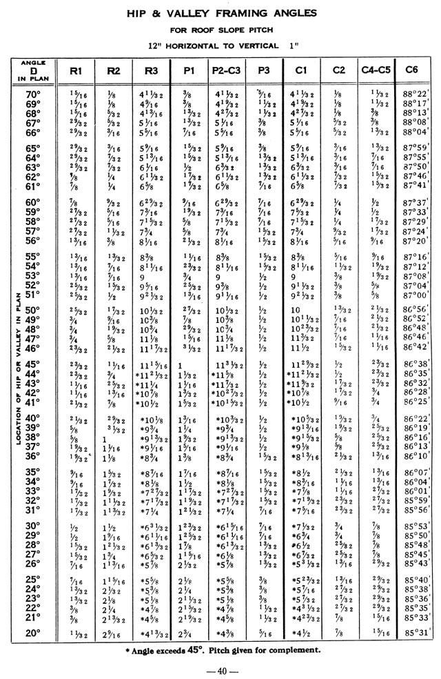
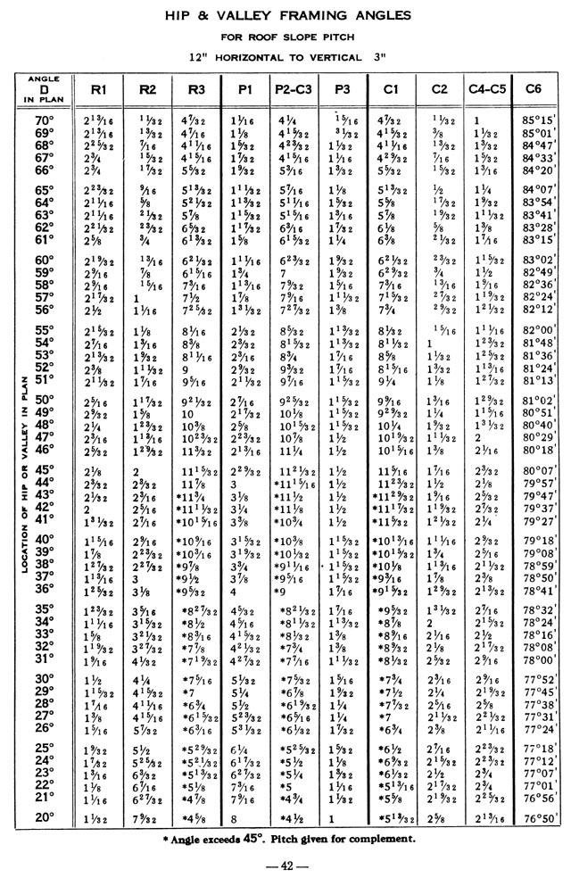
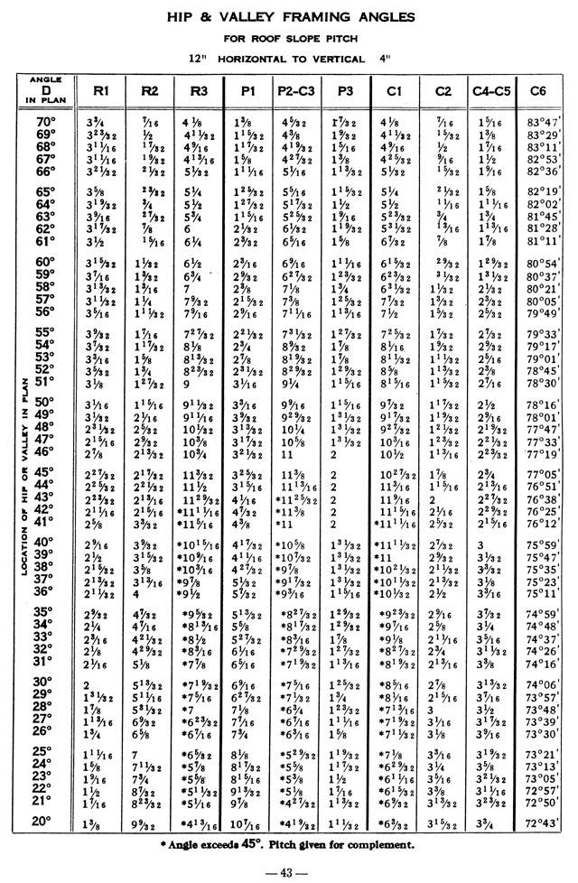
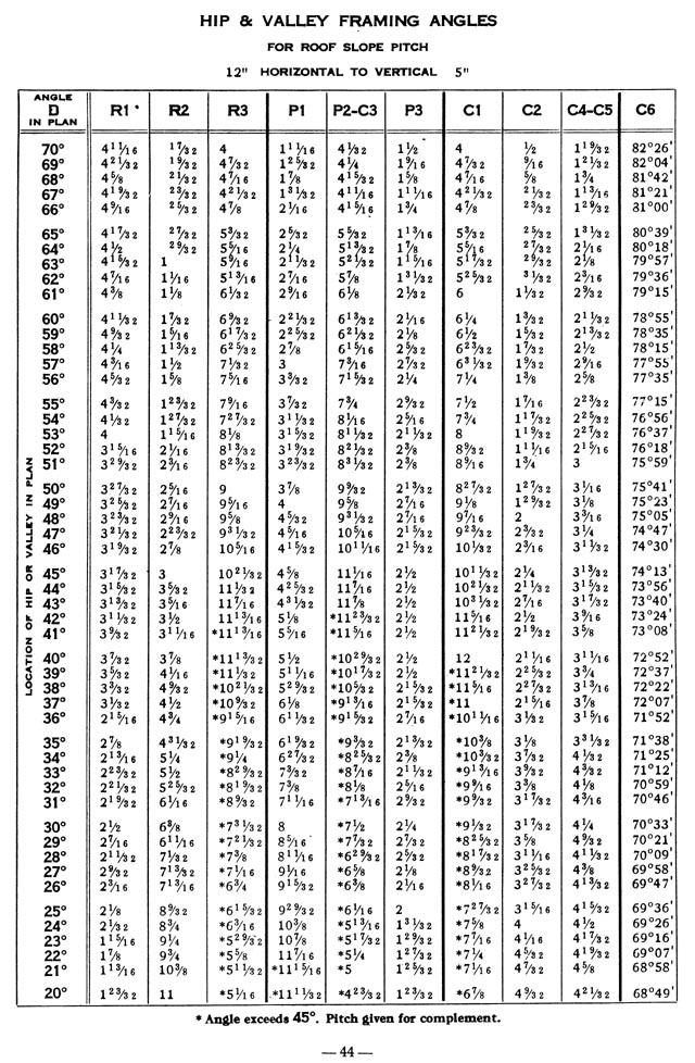
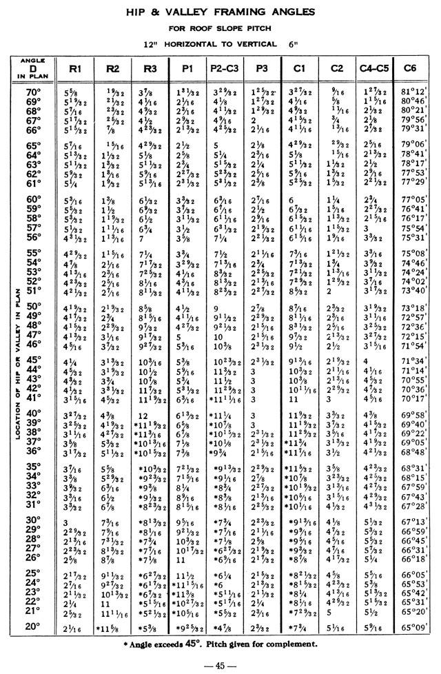
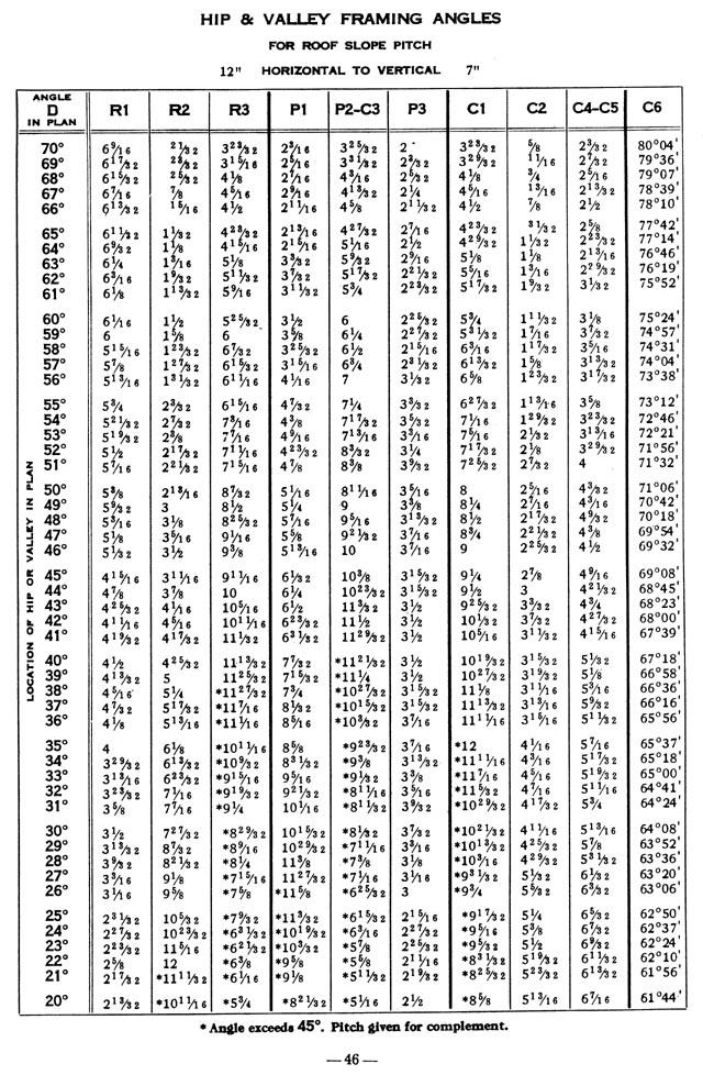
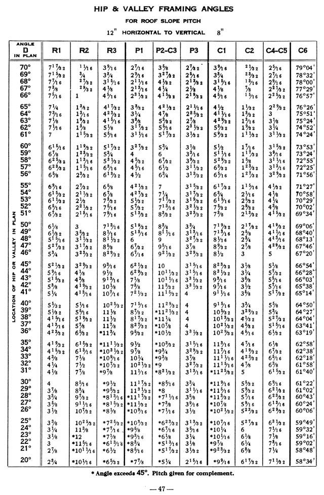
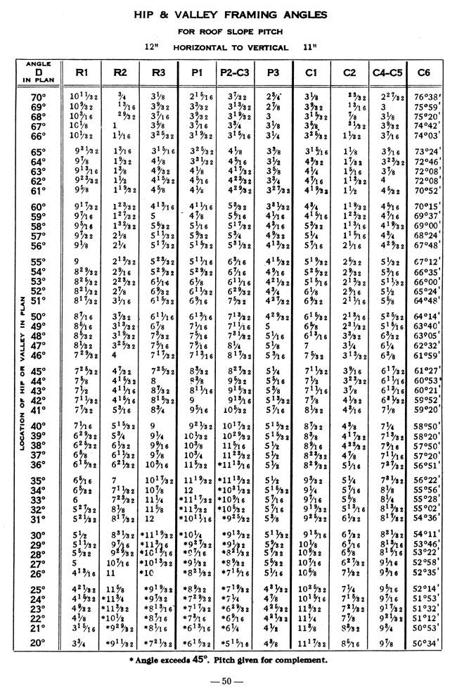
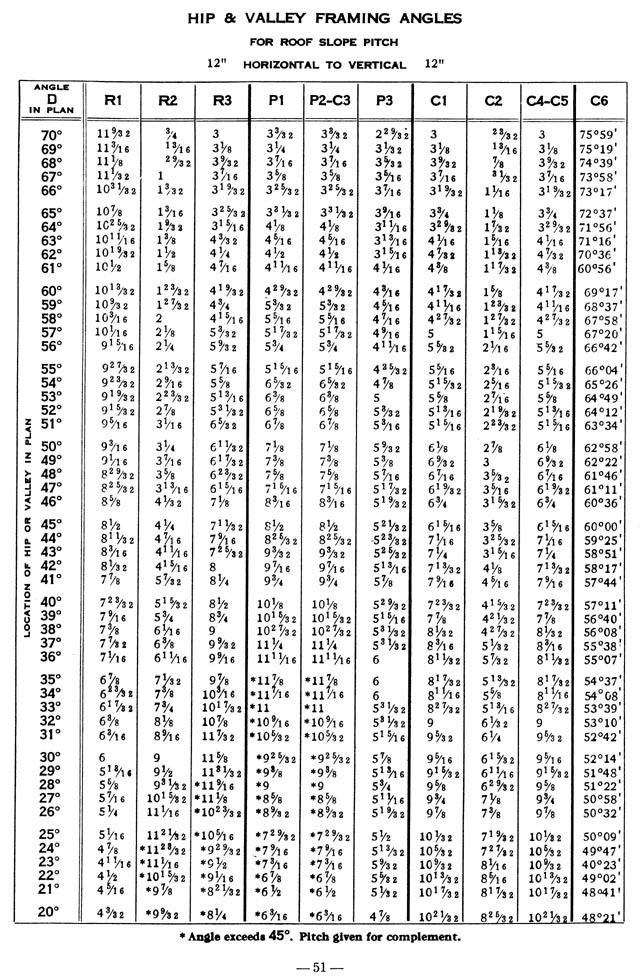
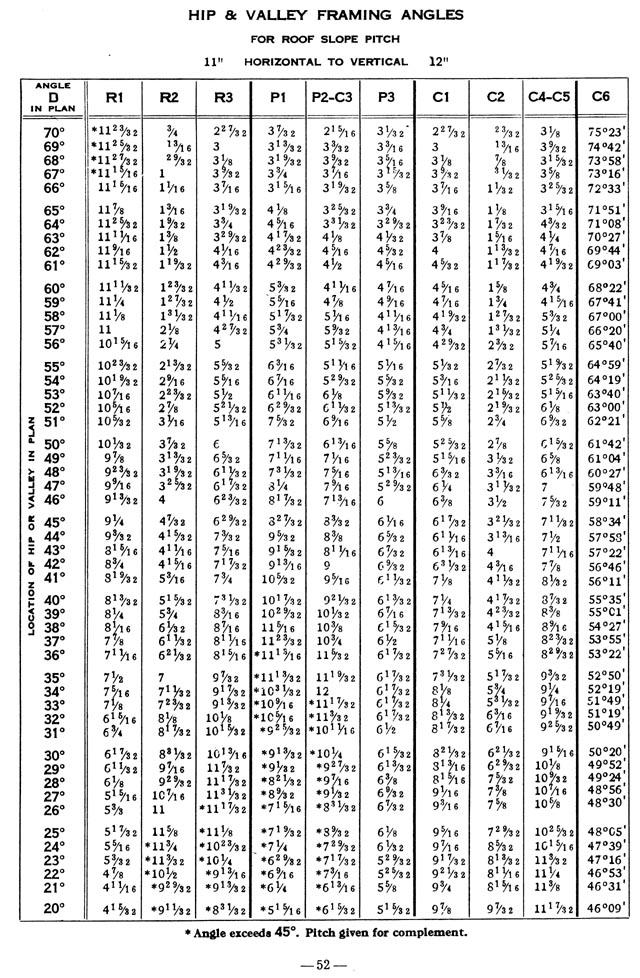
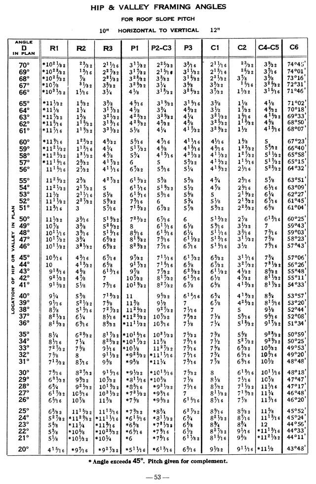
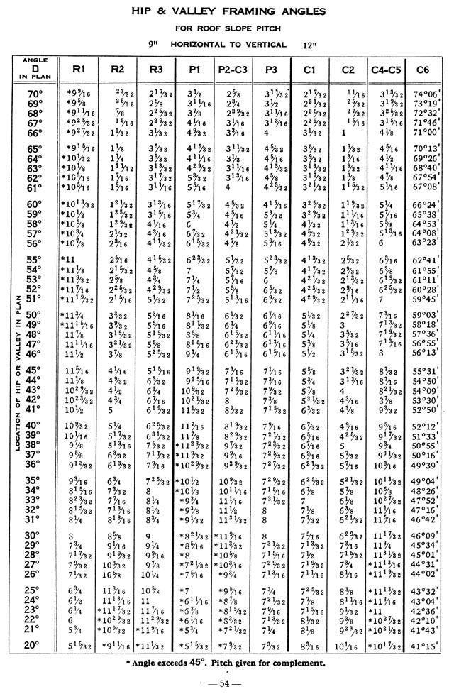
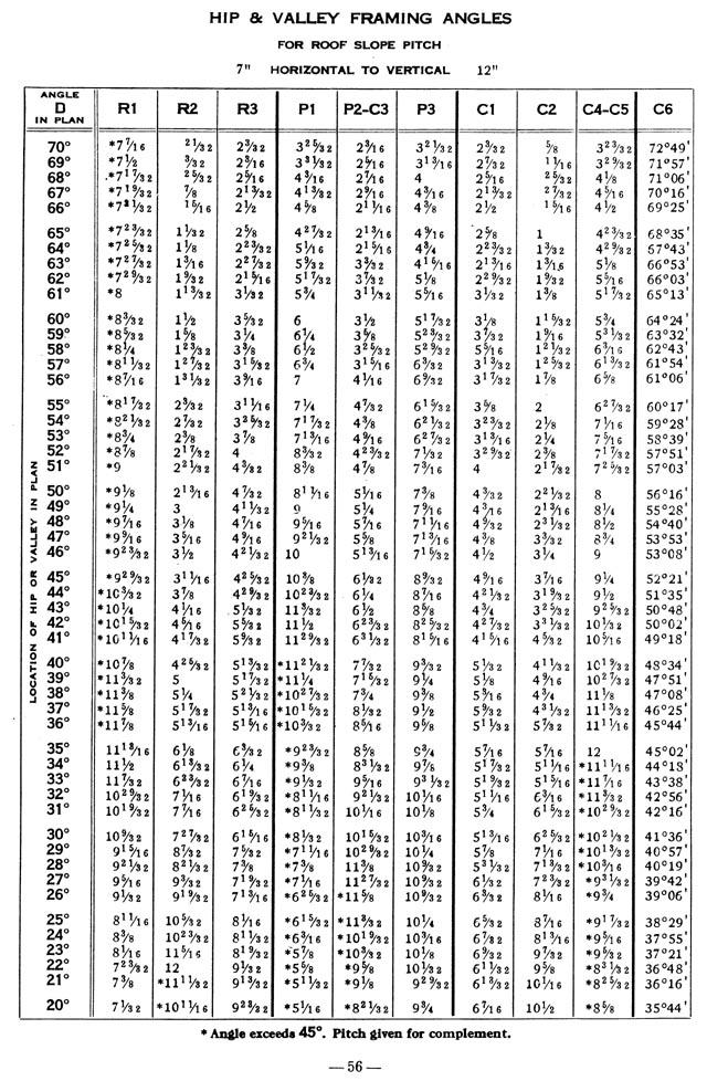
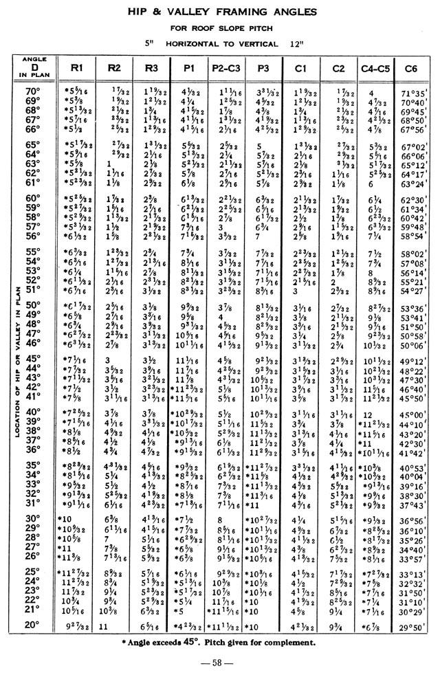
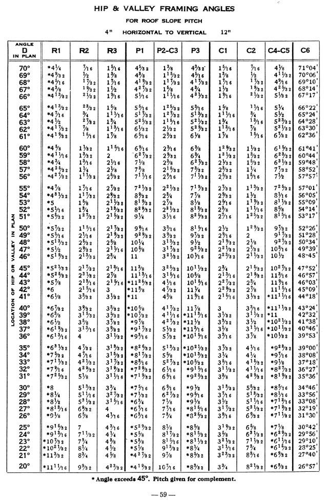
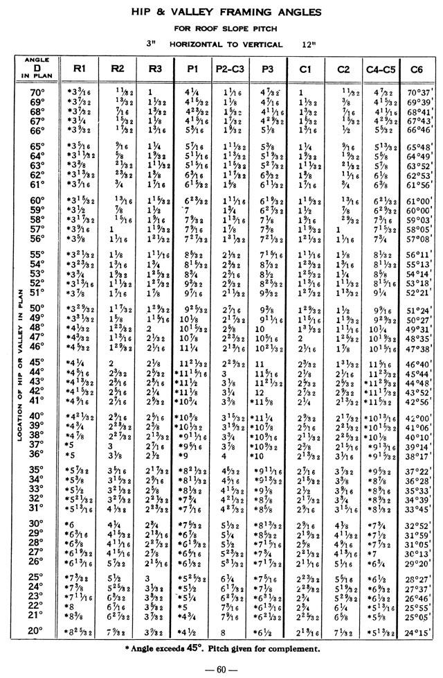
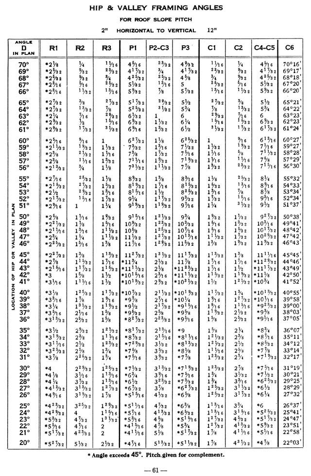
4 Martindales's Bevel Angles: General Notes Page 1 of 1 GENERAL NOTES Bevel corner angles for tapered bins, hoppers, chutes, towers and other tapered structures are dealt with in Part I and hip and valley roof framing angles in Part II. PART I provides diagrams and formulas for finding the pitch of the bevel corner angles for tapered bins, hoppers, chutes, towers, spires, masts and other similar structures. The diagrams furnish the bevel corner angle directly from the side slopes for rectangular bins, hoppers, etc. The formulas provide the means of finding the bevel corner angle for any shaped structure. PART II provides sketches of various roof arrangements, sketches of typical hip and valley roof framing connections, formulas for finding the horizontal position of the hip or valley, formulas for the hip and valley roof framing angles, tables of hip and valley roof framing angles for various roof slopes and hip or valley positions and analytic proof of the formulas given. The sketch of various hip and valley roof arrangements indicate the valus of the horizontal locating angle for hip and valleys for different combinations of roof slopes and intersecting angles. The sketches of typical hip and valley roof framing connections illustrate typical purlin and rafter connections and locate the several bevel framing angles used for making such connections, including angles for cuts, clearance, locating from top or bottom of purlin and other required triangulation. The tables of hip and valley framing angles are given for 23 roof slopes, the even inch pitch roof slopes of vertical and horizontal pitch. For each roof slope the pitches of the twelve framing angles are given at even degree positions of the hip or valley, as indicated by 51 positions of the locating angle D from 20 to 70. The pitches are given to the nearest 1/32" of pitch. This arrangement given the pitches close enough together so that the pitch for any intermediate position of the hip or valley can be found by interpolation, for the slopes given. The formulas are given for the bevel framing angles for the solution of the angles for roof slopes not included in the tables. Analytic proof of the formulas are given for students and others interested, as the formulas are new. These formulas are based upon the roof slope and the horizontal angles between the ridge and valley, for valley framing angles, and between the hip and eave for hip framing angles [contents] [previous page] [next page] file://d:\downloads\martindale\martinpg5.htm PDF created with pdffactory trial version 1/20/2007
5 Martindale's BEVEL ANGLES: Part I, page 6 Page 1 of 1 PART I Beveled Corner Angles Tapered Bins, Hoppers, Chutes, Towers, Spires, Masts, Etc. USE OF DIAGRAMS There are three diagrams covering the full range of slope combinations for rectangular tapered bins, hoppers, chutes, towers, etc., that is, for corners square in plan or horizontal section. The Typical Bin Sketch shown on the following page indicates the slope combinations covered by each diagram. For a particular problem select the diagram that includes sides with slopes corresponding to your problem. It is only necessary to find the correct pitch for one side along the side edge of the diagram, and follow the line to the intersection of the pitch line at the top of the diagram for the other side, and at that point of intersection, the curves show the pitch of the resulting corner angle. The examples given on the page opposite each diagram outlines the procedure more in detail. All pitch lines are shown at 1/8" intervals. The pitch to the nearest 1/16" of pitch can be read by interpolation. Note that the diagrams are for corners SQUARE IN PLAN only. To find the bevel of corners where the sloping sides meet in an acute or obtuse angle in plan, see formulas page 15. Note that the bevel of the corner for any two slopes is the same whether they meet right or left hand to the examples given. Hip corners for tapered towers can be found in the same manner as for bins, as the corners would be the same as an inverted bin with the same slopes. Similarly the beveled corners of any tapered structure such as chutes, masts, spires and the like can be found by reference to the proper diagram. [contents] [previous page] [next page] file://d:\downloads\martindale\martinpg6.htm PDF created with pdffactory trial version 1/20/2007
6 Martindale's BEVEL ANGLES: Part I, page 7 Page 1 of 2 file://d:\downloads\martindale\martinpg7.htm PDF created with pdffactory trial version 1/20/2007
7 Martindale's BEVEL ANGLES: Part I, page 7 Page 2 of 2 [contents] [previous page] [next page] file://d:\downloads\martindale\martinpg7.htm PDF created with pdffactory trial version 1/20/2007
8 Martindale's BEVEL ANGLES: Part I, page 8 Page 1 of 1 EXAMPLES for DIAGRAM NO-1 BIN PROBLEM Given a bin corner, square in plan, one side with 6" horizontal pitch slope, the other side with 4" horizontal pitch slope, to find the resulting bevel angle at the valley. In diagram No. 1, select 6" pitch line on Side A, follow to the intersection with 4" pitch line from Side B. This intersection point lies between the 1 5/8" and 1 3/4" pitch line for angle C7. By interpolation the pitch to the nearest sixteenth is 1 11/16". TOWER PROBLEM Given a tapered tower, square in plan, both sides having a 2" horizontal pitch slope, to find the pitch of the resulting hip corner beveled angle. In diagram No. 1, on Side A select the 2" pitch line, follow to the intersection with the 2" pitch line from Side B. The point of intersection lies between the 1/4" and 3/8" pitch line for angle C7. By interpolation, the pitch to the nearest sixteenth is 5/16". [contents] [previous page] [next page] file://d:\downloads\martindale\martinpg8.htm PDF created with pdffactory trial version 1/20/2007
9 Martindale's BEVEL ANGLES: Part I, page 9 Page 1 of 1 [contents] [previous page] [next page] file://d:\downloads\martindale\martinpg9.htm PDF created with pdffactory trial version 1/20/2007
10 Martindale's BEVEL ANGLES: Part I, page 10 Page 1 of 1 EXAMPLES for DIAGRAM NO-2 BIN PROBLEM Given a bin corner, square in plan, one side with 6" horizontal pitch slope and the other side with 10" vertical pitch slope, to find the resulting bevel angle at the valley. In diagram No. 2, note that Side B is for horizontal pitches and Side C is for vertical pitches. Select 6" line side B and follow to intersection with 10" line from side C. This intersection point lies near the 4 3/8" pitch line for the desired angle C7. [contents] [previous page] [next page] file://d:\downloads\martindale\martinpg10.htm PDF created with pdffactory trial version 1/20/2007
![Martindale's BEVEL ANGLES: Part I, page 11 Page 1 of 1 [contents] [previous page] [next page]](/docs-images/75/72532284/images/11-0.jpg "file://d:\downloads\martindale\martinpg11.htm PDF created with pdffactory trial version www.pdffactory.com 1/20/2007")
11 Martindale's BEVEL ANGLES: Part I, page 11 Page 1 of 1 [contents] [previous page] [next page] file://d:\downloads\martindale\martinpg11.htm PDF created with pdffactory trial version 1/20/2007
12 Martindale's BEVEL ANGLES: Part I, page 12 Page 1 of 1 EXAMPLES for DIAGRAM NO-2 BIN PROBLEM Given a bin corner, square in plan, one side with 10" vertical pitch slope and the other side with 8" vertical pitch slope, to find the resulting bevel angle at the valley. In diagram No. 3, select the 10" line side C and follow to intersection with 8" line from side D. This intersection point lies near the 10" pitch line for the desired angle C7. [contents] [previous page] [next page] file://d:\downloads\martindale\martinpg12.htm PDF created with pdffactory trial version 1/20/2007
13 Martindale's BEVEL ANGLES: Part I, page 13 Page 1 of 1 [contents] [previous page] [next page] file://d:\downloads\martindale\martinpg13.htm PDF created with pdffactory trial version 1/20/2007
14 Martindale's BEVEL ANGLES: Part I, page 15 Page 1 of 1 [contents] [previous page] [next page] file://d:\downloads\martindale\martinpg15.htm PDF created with pdffactory trial version 1/20/2007
15 Martindale's BEVEL ANGLES: Part II, page 16 Page 1 of 1 PART II Hip & Valley Roof Framing Angles COMMENT The following Formulas, Hip and Valley Roof Arrangement Sketch, Typical Connection Sketches and Tables of Hip and Valley Framing Angles, have been prepared to assist in solving the bevel angles required for Hip and Valley roof framing as usually framed. The Hip and Valley Roof Arrangement Sketch page 19 is to aid in finding the horizontal reference angle D used in the formulas and tables. The Typical Connection Sketches pages 20 to 31 incl. are to aid in locating the bevel angle marks and the position of the bevel angles. The Formulas page 18 are for solving the bevel angles not covered by the tables. The Tables of Hip and Valley Framing Angles, pages 40 to 62 incl. are for finding the pitch of the bevel angles directly from the roof slope and horizontal reference angle D of the hip or valley, for the roof slopes included. The Analytic Proof of the formulas, pages 32 to 37 incl. are for reference of students and others interested. [contents] [previous page] [next page] file://d:\downloads\martindale\martinpg16.htm PDF created with pdffactory trial version 1/20/2007
16 Martindale's BEVEL ANGLES: Part II, page 17 Page 1 of 2 HIP & VALLEY ROOF FRAMING ANGLES USE OF SKETCHES, FORMULAS & TABLES OF ANGLES To use the following sketches, formulas and tables of hip & valley framing angles, the user should be familiar with the arrangement of purlins and hip and valley rafters assumed as the basis of the formulas. This arrangement is described basically under "Notes on Formulas" below. Because the formulas are based upon the roof slope and the horizontal angle between the ridge and the valley framing angles, and between the eave and the hip framing angles, the first procedure is to find this hoizontal angle to degrees and minutes. This horizontal angle is marked D and is used in the formulas, sketches and tables Sketch #1 shows several hip and valley roof arrangements and locates angle D for each arrangement. Formulas for calculating angle D from the two meeting roof slopes and the horizontal angle between the ridges for valleys, and between the eaves for hips, are given for each case. The twelve connection sketches #2 to #13 show six pairs of hip and valley rafter connections for the same purlin. Note that channel, beam and tee purlins are shown, and that connections with clips above and below the purlin are shown so that types required for ridge and eave purlin can be selected. Connections with flange clips and bent plates are also shown. Connections using both single and multiple punching are also shown. The connections are detailed for punched and riveted work. The working points have been projected from one viwe to another and to a diagram of the roof, to assist in following the working points from one face to another. The small triangulation incidental to calculating the drop of hip rafters for clearance, for making cuts and for locating from top or bottom of purlin, are shown and elaborated. The purpose of the connection sketches is to locate and orient the several bevel angles and to indicate their use for cuts, clearance, etc., as well as the bend and the bevel of the connection. Angle marks for other types of connections can be located by comparing with somewhat similar types or from the location given with the formulas. Having located the desired angle marks the pitches can be found in the Tables of Hip & Valley Framing Angles, provided the roof slope you want is given, and by use of the formulas for other roof slopes. NOTES ON FORMULAS, PAGE 18 The formulas for the Hip & Valley Roof Framing Angles are based upon the roof slope and angle D. The twelve bevel angles formulated and given in the tables, cover all the bevel angles formed by two members with web and flange faces meeting in a three dimensional position from each other, when framed as follows- 1. All framing members have web and flange faces square with each other. 2. Rafter webs are in a vertical plane. file://d:\downloads\martindale\martinpg17.htm PDF created with pdffactory trial version 1/20/2007
17 Martindale's BEVEL ANGLES: Part II, page 17 Page 2 of 2 3. Rafters are parallel to hip or valley. 4. Webs of purlins are at right angles to the roof line. 5. Purlins are parallel with the ridges. 6. The ridge and eave are level. 7. Angles A and D are in a level plane. [contents] [previous page] [next page] file://d:\downloads\martindale\martinpg17.htm PDF created with pdffactory trial version 1/20/2007
18 Martindale's BEVEL ANGLES: Part II, page 18 Page 1 of 1 M A R K S & F O R M U L A S HIP & VALLEY ROOF FRAMING CONNECTION ANGLES S & SS = Roof Slopes A & A' = Horizontal angles between ridges and between eaves. D = Horizontal angles between ridge and valley or eave and hip. Marked D, D', DD & DD' for different roof arrangements shown Sketch #1. B E V E L C O N N E C T I O N A N G L E S MARK LOCATION FORMULA R1 Pitch of Hip or Valley Rafter. tan R1 = tan S sin D R2 R3 P1 P2 P3 C1 C2 C3 C4 C5 C6 Angle on Hip or Valley Rafter web locating intersection of Purlin web. Angle on Hip or Valley Rafter flg. locating intersection of Purlin web. Angle on Purlin web, locating intersection of Hip or Valley Rafter web. Angle on Purlin flg. locating intersection of Hip or Valley Rafter web. Angle on Purlin web, locating intersection of Hip or Valley Rafter flg. Complement of the acute angle between Purlin web and Hip or Valley web. Complement of the acute angle between Purlin web and Hip or Valley flange. Angle between Purlin web and a plane perpendicular to both web and flange of Hip or Valley Rafter. Angle on a plane perpendicular to web and flange of Hip or Valley Rafter, locating intersection of Purlin web. Angle between Roof plane and Hip or Valley Rafter flange. Angle between Roof plane and Hip or Valley Rafter web. tan R2 = sin S cos S cos D cotan D tan R3 = sin S cos S cos D csc R1 tan P1 = sin S cotan D tan P2 = cos S cotan D tan P3 = cos D sin R1 cos R1 sec S tan C1 = sin P1 cotan S tan C2 = tan R2 cos R3 tan C3 = cotan D cos S tan C4 = sin R1 cotan D tan C5 = sin R1 cotan D tan C6 = tan D csc R1 Analytic proof of formulas given on pages 32 to 37. [contents] [previous page] [next page] file://d:\downloads\martindale\martinpg18.htm PDF created with pdffactory trial version 1/20/2007
19 Martindale's BEVEL ANGLES: Part I, page 19 Page 1 of 1 [contents] [previous page] [next page] file://d:\downloads\martindale\martinpg19.htm PDF created with pdffactory trial version 1/20/2007
20
21
22
23
24
25
26
27
28
29
30
31
32
33
34
35
36
37
38 Martindale's BEVEL ANGLES: Part II, page 38 Page 1 of 1 NOTES ON HIP & VALLEY FRAMING ANGLE TABLES Where the difference in pitch for any angle for one degree of angle D exceeds 1/16", the pitch to the nearest 1/16" can be found by interpolating the minutes of angle D. The greatest difference to be found in the tables is 11/16" and in most cases much less. For example, given an 8" vertical pitch roof slope and angle D=56 20', to find pitch of angle P1. On page 47 the pitch for 56 is 4-1/2" and for 57 is 4-5/16". Subtract 1/16" from the pitch for 56 and we get the correct pitch for 56 20' to be 4-7/16". Note that in some positions the pitch of an angle becomes less as angle D increases, and in other positions they increase. The pitch will reduce or increase accordingly. Angle C6 is given in degrees and minutes to facilitate adding together the values of C6 for each of two sides of a valley corner angle for bins, hoppers, etc. The full inside valley angle C8 for such corners can be found by adding together the angular value of C6 for each of the two sloping sides. [contents] [previous page] [next page] file://d:\downloads\martindale\martinpg38.htm PDF created with pdffactory trial version 1/20/2007
39

40
41
42
43
44
45
46

47

48
49
50
51
52
53

54
55

56
57
58
59
60

61
Backed. Valley. Valley. Timber
 Valley Rafter Cross Sections The projected point of intercept of the jack rafters lies below the Valley rafter shoulders. The jack rafters plane the same regardless of whether the Valley is backed or not.
SQUARE CUT ANGLES: General Model for Rafter and Purlin Angles
 General Model for Rafter and Purlin Angles Working point for Purlin Angles (as per previous diagrams) A8 A9 tan R R tan Dihedral Angle = SS The same kernel geometry was required to solve backing angle
COMPOUND ROOFS WORKSHOP - Introduction Complex roof geometry is a challenge most framers face eventually. These problems can be solved either
 COMPOUND ROOFS WORKSHOP - Introduction Complex roof geometry is a challenge most framers face eventually. These problems can be solved either mathematically or visually, but the complete carpenter will
Orthographic Projection 1
 Orthographic Projection 1 What Is Orthographic Projection? Basically it is a way a representing a 3D object on a piece of paper. This means we make the object becomes 2D. The difference between Orthographic
RAFTER and PURLIN FORMULAS:
 RAFTER and PURLIN FORMULAS: It would be an exercise in futility to attempt to enumerate all the possible formulas, as every case is different. Knowledge of how the angles relate to the overall roof structure
Thinking Irregularly. Timber Framers Guild Eastern Conference Roanoke, Virginia November 9, 2006
 Thinking Irregularly Timber Framers Guild Eastern Conference Roanoke, Virginia November 9, 2006 Basic information Main Roof slope is 9 : 12 Adjacent Roof slope is 10-1/2 : 12 Run of main roof is 12 The
4.4 Slope and Graphs of Linear Equations. Copyright Cengage Learning. All rights reserved.
 4.4 Slope and Graphs of Linear Equations Copyright Cengage Learning. All rights reserved. 1 What You Will Learn Determine the slope of a line through two points Write linear equations in slope-intercept
GLOSSARY OF TERMS SECTION 8
 GLOSSARY OF TERMS SECTION 8 Anchor Bolt Angle Base Plate Bay Blocking CCB Centerline Chord Cladding Clip Closure Strip An A-307 steel bolt embedded in the concrete footing to anchor the base plate of the
In this 3D model, facets appear as semi-transparent to reveal overhangs.
 Sunsite TM Report ebruary 21, 2017 123 Main St., City, ST 00000 In this 3D model, facets appear as semi-transparent to reveal overhangs. Report Details Roof Details Total Area =10,734 sq ft Total Roof
Trade of Metal Fabrication. Module 6: Fabrication Drawing Unit 13: Parallel Line Development Phase 2
 Trade of Metal Fabrication Module 6: Fabrication Drawing Unit 13: Parallel Line Development Phase 2 Table of Contents List of Figures... 4 List of Tables... 5 Document Release History... 6 Module 6 Fabrication
Roofing Terms Explained
 FEATURES Roofing Terms Explained Rafter: The roofing members that form the slopes which basically support the external cladding of the roof. Ridge Beam: The horizontal member to which the top ends of the
COMPONENTS OF THE CLICKFAST FASCIA AND GUTTER SYSTEM 5: INTERNAL MITRE
 INTRODUCING THE CLICKFAST FASCIA AND GUTTER SYSTEM The Clickfast Fascia and Gutter System was originally designed by Stratco and has proven to be the most successful fascia and gutter system in Australia
CCFSS Technical Bulletin
 CCFSS Technical Bulletin Vol. 12, No. 1 February 2003 FREQUENTLY ASKED QUESTIONS CONCERNING THE AISI BASE TEST METHOD AND THE USE OF THE AISI ANCHORAGE EQUATIONS Answers Provided by the AISI Task Committee
Verge Flashing. Verge Flashing. Only use if flashings requirements can be site measured before ordering. Verge Clip
 Tolerance Detail (recommended) Verge Closure Verge Channel Verge Clip Verge Flashing VERGE CHANNEL RIVETTED TO EUROSEAM AT APPROX 400MM CENTRES USING 4.8 X 12MM RIVETS. NB: DO NOT RIVET AT HALTER POSITION
CURVED ROOF ASSEMBLY INSTRUCTIONS ATTACHED VERANDAH. Your supplementary guide to building an ATTACHED CURVED ROOF VERANDAH or PATIO BEFORE YOU START
 ROOF ATTACHED VERANDAH ASSEMBLY INSTRUCTIONS Your supplementary guide to building an ATTACHED ROOF VERANDAH or PATIO This set of instructions should be used in conjunction with the Stratco instruction
HIP AND GABLE ROOF COMPONENTS
 Page 18. VU20976 Roof Framing HIP AND GABLE ROOF COMPONENTS Plan view of the hip and gable roof that you are going to build. Again, don't be tempted just to look the names, put in a bit more effort to
2.1 Sun Elevation Angle (SEA): The peak Angle (in degrees) between the sun and horizon.
: The peak Angle (in degrees) between the sun and horizon.") Solar SnowMax Shade Angle Analysis Contents 1.0 Scope 2.0 Terminology 3.0 Shade Length Calculations 1.0 Scope 1.1 This document outlines the steps taken to determine how much shade, in inches, is present
Solar SnowMax Shade Angle Analysis Contents 1.0 Scope 2.0 Terminology 3.0 Shade Length Calculations 1.0 Scope 1.1 This document outlines the steps taken to determine how much shade, in inches, is present
SolarMount-I INSTALLATION MANUAL Broadway Boulevard NE Albuquerque, NM USA A HILTI GROUP COMPANY
 SolarMount-I INSTALLATION MANUAL 2011 by Unirac, Inc. All rights reserved. Pub 110518-1ii, May 2011 A HILTI GROUP COMPANY R 1411 Broadway Boulevard NE Albuquerque, NM 87102-1545 USA IMPORTANT! Unirac Inc.
Installation Manual. Future Shingle Products
 Installation Manual Future Shingle Products TITLE REVISED 7/4/2011 Future Shingle Installation Manual is a component of Future Roof, Inc. and as such is intended to be used with Future Roof products only.
Surveying & Measurement. Detail Survey Topographic Surveying
 Surveying & Measurement Detail Survey Topographic Surveying Introduction Mapping surveys are made to determine the relief of the earth s surface and locate critical points on it. to determine the locations
MEM05 Metal and Engineering Training Package SAMPLE. Learner guide Version 1. Training and Education Support Industry Skills Unit.
 MEM05 Metal and Engineering Training Package MEM05039B Perform advanced geometric development - conical Learner guide Version 1 Training and Education Support Industry Skills Unit Meadowbank Product Code:
In this 3D model, facets appear as semi-transparent to reveal overhangs.
 SunSite TM Report 3 Main St., City, ST 00000 In this 3D model, facets appear as semi-transparent to reveal overhangs. Report Details Roof Details Total Area =2,609 sq ft Total Roof Facets =13 Predominant
DUTCH GABLE FREESTANDING CARPORT
 DUTCH GABLE FREESTANDING CARPORT STRATCO OUTBACK ASSEMBLY INSTRUCTIONS. Your complete guide to building a FREESTANDING Outback DUTCH GABLE CARPORT BEFORE YOU START Carefully read these instructions. If
Shingle Installation Guide
 Installation Guide Roof Framing Information Installation Installation Accessory Installation Estimating Data General Information Roof Framing Information It is the responsibility or roofers, building contractors
Rafter Cutting Basics
 Rafter Cutting Basics Understanding basic rafter principles is key to efficiently framing even the most complex roofs There are many ways to cut rafters. In more than 25 years of framing houses, I have
Copyrighted Material. Copyrighted Material. Copyrighted. Copyrighted. Material
 Engineering Graphics ORTHOGRAPHIC PROJECTION People who work with drawings develop the ability to look at lines on paper or on a computer screen and "see" the shapes of the objects the lines represent.
The e-stick Roof Installation Guide
 The e-stick Roof Installation Guide for carpenters and builders to correctly install Wesbeam e-stick LVL roof framing products roof battens for sheet roofs, underpurlins and struts. e-batten The veneers
DUTCH GABLE CARPORT RECOMMENDED INSTRUCTION MANUAL
 DUTCH GABLE CARPORT RECOMMENDED INSTRUCTION MANUAL Table of Contents Introduction 2 Components 3 Step 1a Marking out the Perimeter of the Carport with Footing only 4 Step 2a Footing Set-Out for Concrete
Graphs of other Trigonometric Functions
 Graphs of other Trigonometric Functions Now we will look at other types of graphs: secant. tan x, cot x, csc x, sec x. We will start with the cosecant and y csc x In order to draw this graph we will first
Trade of Toolmaking. Module 6: Introduction to CNC Unit 2: Part Programming Phase 2. Published by. Trade of Toolmaking Phase 2 Module 6 Unit 2
 Trade of Toolmaking Module 6: Introduction to CNC Unit 2: Part Programming Phase 2 Published by SOLAS 2014 Unit 2 1 Table of Contents Document Release History... 3 Unit Objective... 4 Introduction... 4
Hugger Installation. Roof Hugger, LLC P: P.O. Box 1027 F: Odessa, FL
 RECEIVING MATERIALS: ROOF HUGGERS are typically placed on wood pallets 3-5 wide and approximately 10 long weighing up to 5,000 lbs. ROOF HUGGERS are shipped via closed van for LTL less than truckload quantities
ROOF FRAMING INFORMATION BATTEN INSTALLATION CORONA SHAKE INSTALLATION ACCESSORY INSTALLATION ESTIMATING DATA GENERAL INFORMATION
 ROOF FRAMING INFORMATION BATTEN INSTALLATION CORONA SHAKE INSTALLATION ACCESSORY INSTALLATION ESTIMATING DATA GENERAL INFORMATION ROOF FRAMING INFORMATION It is the responsibility or roofers, building
Math 1205 Trigonometry Review
 Math 105 Trigonometry Review We begin with the unit circle. The definition of a unit circle is: x + y =1 where the center is (0, 0) and the radius is 1. An angle of 1 radian is an angle at the center of
MULTISPAN GABLE WITH HIP END ATTACHED PATIO
 MULTISPAN GABLE WITH HIP END ATTACHED PATIO STRATCO OUTBACK ASSEMBLY INSTRUCTIONS. Your supplementary guide to building an ATTACHED MULTISPAN GABLE VERANDAH or PATIO WITH HIP END This set of instructions
Plan View 12:12 12:12
 Level 2 Roof Cutter's Task Model Each participant is to layout and cut one hip rafter, two jack rafters, and one end of a purlin rafter. There will be four participants that cut and build each task odel.
Chappell Universal Framing Square
 Chappell Universal Framing Square 0 0 0 0 The Chappell Universal Square tm Puts a Wealth of Building Knowledge Right in the Palm of your Hand... Unlock the mystery of unequal pitch Compound roof framing
SECTION IV. Covers Trough Ends Trough Conveyor Screws Discharges Inlets Special Features
 Special Features SECTION IV SPECIAL FEATURES SECTION IV Covers...109 Trough Ends...110 Trough...111 Conveyor Screws...114 Discharges...119 Inlets...120 Special Features The information presented in this
ROOFING APPLICATION STANDARD (RAS) No. 115 STANDARD PROCEDURES FOR ASPHALTIC SHINGLE INSTALLATION
 No. 115 STANDARD PROCEDURES FOR ASPHALTIC SHINGLE INSTALLATION") ROOFING APPLICATION STANDARD (RAS) No. 115 STANDARD PROCEDURES FOR ASPHALTIC SHINGLE INSTALLATION 1. Scope 4. Underlayment 2. 1.1 This roofing application standard has been developed to provide a responsive
ROOFING APPLICATION STANDARD (RAS) No. 115 STANDARD PROCEDURES FOR ASPHALTIC SHINGLE INSTALLATION 1. Scope 4. Underlayment 2. 1.1 This roofing application standard has been developed to provide a responsive
Geometry Vocabulary Book
 Geometry Vocabulary Book Units 2-4 Page 1 Unit 2 General Geometry Point Characteristics: Line Characteristics: Plane Characteristics: RELATED POSTULATES: Through any two points there exists exactly one
ROOFING APPLICATION STANDARD (RAS) No. 115 STANDARD PROCEDURES FOR ASPHALTIC SHINGLE INSTALLATION
 No. 115 STANDARD PROCEDURES FOR ASPHALTIC SHINGLE INSTALLATION") ROOFING APPLICATION STANDARD (RAS) No. 115 STANDARD PROCEDURES FOR ASPHALTIC SHINGLE INSTALLATION 1. Scope 4. Underlayment 2. 1.1 This roofing application standard has been developed to provide a responsive
ROOFING APPLICATION STANDARD (RAS) No. 115 STANDARD PROCEDURES FOR ASPHALTIC SHINGLE INSTALLATION 1. Scope 4. Underlayment 2. 1.1 This roofing application standard has been developed to provide a responsive
Chappell Universal Framing Square
 Chappell Universal Framing Square 0 0 0 0 The Chappell Universal Square tm Puts a Wealth of Building Knowledge Right in the Palm of your Hand... Unlock the mystery of unequal pitch Compound roof framing
SolarMount-I INSTALLATION MANUAL
 SolarMount-I INSTALLATION MANUAL 2010 by Unirac, Inc. All rights reserved. Pub 100621-1ii, June 2010 R A HILTI GROUP COMPANY 1411 Broadway Boulevard NE Albuquerque, NM 87102-1545 USA IMPORTANT! Unirac
Roof Framing. Student Edition
 Student Edition Developed by the Curriculum and Instructional Materials Center for the Trade and Industrial Education Division Oklahoma Department of Career and Technology Education 00-00000 TI3673 Copyright
SolarMount (E)volution
volution") SolarMount (E)volution SOLARMOUNT (E)VOLUTION: THE BEST JUST GOT BETTER. Engineering, Excellence, and Ease. Performance Engineered for versatility and reduced installation time, SolarMount (E)volution
SolarMount (E)volution SOLARMOUNT (E)VOLUTION: THE BEST JUST GOT BETTER. Engineering, Excellence, and Ease. Performance Engineered for versatility and reduced installation time, SolarMount (E)volution
In this 3D model, facets appear as semi-transparent to reveal overhangs.
 olar Report In this 3D model, facets appear as semi-transparent to reveal overhangs. Report Details Roof Details Total Area =10,73 sq ft Total Roof acets =16 Predominant Pitch =0/12 umber of tories >1
Roof Tutorial Wall Specification
 Roof Tutorial The majority of Roof Tutorial describes some common roof styles that can be created using settings in the Wall Specification dialog and can be completed independent of the other tutorials.
The reciprocal identities are obvious from the definitions of the six trigonometric functions.
 The Fundamental Identities: (1) The reciprocal identities: csc = 1 sec = 1 (2) The tangent and cotangent identities: tan = cot = cot = 1 tan (3) The Pythagorean identities: sin 2 + cos 2 =1 1+ tan 2 =
CLEARSPAN GABLE STRATCO OUTBACK ASSEMBLY INSTRUCTIONS. WITH GAZEBO END ATTACHED PATIO
 CLEARSPAN GABLE WITH GAZEBO END ATTACHED PATIO STRATCO OUTBACK ASSEMBLY INSTRUCTIONS. Your supplementary guide to building an ATTACHED CLEARSPAN GABLE VERANDAH or PATIO WITH GAZEBO END This set of instructions
PURLIN SPACINGS SB SAFETY MESH INSULATION ROOF SHEET PUNCH DETAIL A110 SB A130 SB A100 SB A145 SB A80 SB A140 SB 100 X 102 Y 110 X 112 Y 130 X 132 Y
 PURLIN PUNCHINGS SAFET MESH INSULATION ROOF SHEET BOTTOM OF PUNCHING TOP OF BRIDGING 620mm, 920mm, 1220mm, 1370mm or 1520mm PURLIN SPACINGS 80 82 102 110 112 130 132 140 142 145 147 A80 A A110 A130 A140
Special Roofs and Vertical Slating
 Special Roofs and Vertical Slating Roofs falling into the category of "special" roofs have the following characteristics: (a) any roof slope equal to or greater than the minimum pitch for the size of slate
ENGINEERING GRAPHICS
 ENGINEERING GRAPHICS CLASS - XII (046) DESIGN OF THE QUESTION PAPER Time : 3 Hrs Max. Marks : 70 The weightage of the distribution of marks over different contents of the question paper shall be as follows:
Installation Instructions
 Installation Instructions SHARK VENT XLP / XTRA Page Installation Considerations 3 Shark Vent XLP & Xtra General Installation 4 Steep Pitch Guidelines 5 Asphalt Shingles Detail 6 Ridge Beam Detail 7 Hip
Viva Synthetic Thatch Installation Instructions
 Viva Synthetic Thatch Installation Instructions Overview Structure This instruction manual is for the installation of VIVA on an open battened roof frame. Structure should be framed with weatherable wood
Skewed connections result when members frame to each
 Design of Skewed Connections LARRY KLOIBER and WILLIAM THORNTON ABSTRACT Skewed connections result when members frame to each other at an angle other than 90º. This paper provides some guidance in the
VENTED GABLE DETAIL ROOF PANEL GABLE FLASHING 24" C/C MAX. BUTYL SEALANT TAPE ROOF PURLIN FLASH AB-1, AB-2, AB-3, OR AB-4
 ROOF PANEL GABLE FLASHING FASTENER @ 24" C/C MAX. ROOF PURLIN BUTYL SEALANT TAPE FLASH AB-1, AB-2, AB-3, OR AB-4 FASTENER @ EVERY MAJOR RIB OR 12" C/C MAX. F-J TRIM FABRAL ALUMINUM SOFFIT FASTENER 24"
2x6. 2x8. 2x10. Size. 2-2x10 8'-5" w/ 2 NJ 7'-3" w/ 2 NJ
 1 Rafter Size Spacing Allowable span 24" 11'-9" 24" 2x6 14'-1" 2x4 12" 15'-6" 12" 24" 14'-10" 24" 2x8 18'-2" 2x6 12" 20'-5" 12" 24" 18'-2" 24" 2x10 22'-3" 2x8 12" 25'-8" 12" 24" 21'-0" 24" 2x12 25'-9"
Installation Manual. Future Roof Shingle / Slate Products
 Installation Manual Future Roof Shingle / Slate Products REVISED 14/09/2010 Future Roof Shingle Installation Manual is a component of Future Roof, Inc. and as such is intended to be used with Future Roof
Chapter 51: Sidewall Overhang(s) Only - Enclosed
 Only - Enclosed") Chapter 51: Sidewall Overhang(s) Only - Enclosed Most Common Mistakes: 1. Incorrect eave height. 2. Placing eave girt below truss tails. 3. Fascia board top edges not bevel cut to match roof slope. 4.
Chapter 51: Sidewall Overhang(s) Only - Enclosed Most Common Mistakes: 1. Incorrect eave height. 2. Placing eave girt below truss tails. 3. Fascia board top edges not bevel cut to match roof slope. 4.
SuperFOIL Insulation. Solutions Guide. Pitched Roof - Under Rafter
 SuperFOIL Insulation Solutions Guide Pitched Roof - Under Rafter SF19+ Pitched Roof Under Rafter Solutions CONSTRUCTION THICKNESS R -VALUE EXTERNAL SURFACE - 0.040 TILES / SLATES 10mm - BATTEN CAVITY 25mm
Installation Instructions for Solar Snow Pad (SSP-T-3)
") Installation Instructions for Solar Snow Pad (SSP-T-3) Warning- Do not use this product on solar arrays where the calculated array snow loads exceed 50 pounds per square foot (psf). Most solar panels are
Installation Instructions for Solar Snow Pad (SSP-T-3) Warning- Do not use this product on solar arrays where the calculated array snow loads exceed 50 pounds per square foot (psf). Most solar panels are
POLAR FUNCTIONS. In Precalculus students should have learned to:.
 POLAR FUNCTIONS From the AP Calculus BC Course Description, students in Calculus BC are required to know: The analsis of planar curves, including those given in polar form Derivatives of polar functions
Fastener Schedule. a, b, c. FASTENER Roof 3-8d (2 1 / ) / ) 3-10d. 3-10d ( ) 3-16d box nails. (3 1 2 toe nails on one side
 / ) 3-10d. 3-10d ( ) 3-16d box nails. (3 1 2 toe nails on one side") ITEM 1 DESCRIPTION OF BUILDING ELEMENTS Blocking between joists or rafters to top plate, toe 2 Ceiling joists to plate, toe 3 4 5 6 Ceiling joists not attached to parallel rafter, laps over partitions,
ITEM 1 DESCRIPTION OF BUILDING ELEMENTS Blocking between joists or rafters to top plate, toe 2 Ceiling joists to plate, toe 3 4 5 6 Ceiling joists not attached to parallel rafter, laps over partitions,
3.1 General Provisions
 WOOD FRAME CONSTRUCTION MANUAL 107 3.1 General Provisions 3.1.1 Prescriptive Requirements The provisions of this Chapter establish a specific set of resistance requirements for buildings meeting the scope
FACULTY OF ENGINEERING DESIGN AND PRODUCTION ENGINEERING DEPARTMENT. Credit Hour System Metrology Lab 1 MDP 240. Sine Bars. Metrology laboratory
 FACULTY OF ENGINEERING DESIGN AND PRODUCTION ENGINEERING DEPARTMENT Report On: Credit Hour System Metrology Lab 1 MDP 240 (13) Sine Bars Metrology laboratory Class No: B.N. Student Name Remark Signature
Turada Hardwood Shingles and Shakes Installation instructions
 1. General 1.1 Maximum Exposure: Maximum exposure for wood shingles and shakes shall comply with Table 1 herein, unless specifically specified in the roof assemblies Product Approval. 1.2 Solid and Spaced
Pembroke Hopkins Park Construction Outreach Program E S. Rd., Pembroke Township, IL Tel: (815) Fax: (815)
 Fax: (815)") Pembroke Hopkins Park Construction Outreach Program 13355 E. 3000 S. Rd., Pembroke Township, IL 60958 Tel: (815) 944-8897 Fax: (815) 944-5675 Competencies / Objectives Level One MODULE 93300-01 - NAILS,
Pembroke Hopkins Park Construction Outreach Program 13355 E. 3000 S. Rd., Pembroke Township, IL 60958 Tel: (815) 944-8897 Fax: (815) 944-5675 Competencies / Objectives Level One MODULE 93300-01 - NAILS,
GE 6152 ENGINEERING GRAPHICS
 GE 6152 ENGINEERING GRAPHICS UNIT - 4 DEVELOPMENT OF SURFACES Development of lateral surfaces of simple and truncated solids prisms, pyramids, cylinders and cones - Development of lateral surfaces of solids
5.1 Graphing Sine and Cosine Functions.notebook. Chapter 5: Trigonometric Functions and Graphs
 Chapter 5: Trigonometric Functions and Graphs 1 Chapter 5 5.1 Graphing Sine and Cosine Functions Pages 222 237 Complete the following table using your calculator. Round answers to the nearest tenth. 2
Chapter 9 Linear equations/graphing. 1) Be able to graph points on coordinate plane 2) Determine the quadrant for a point on coordinate plane
 Be able to graph points on coordinate plane 2) Determine the quadrant for a point on coordinate plane") Chapter 9 Linear equations/graphing 1) Be able to graph points on coordinate plane 2) Determine the quadrant for a point on coordinate plane Rectangular Coordinate System Quadrant II (-,+) y-axis Quadrant
Chapter 9 Linear equations/graphing 1) Be able to graph points on coordinate plane 2) Determine the quadrant for a point on coordinate plane Rectangular Coordinate System Quadrant II (-,+) y-axis Quadrant
Chapter 1 and Section 2.1
 Chapter 1 and Section 2.1 Diana Pell Section 1.1: Angles, Degrees, and Special Triangles Angles Degree Measure Angles that measure 90 are called right angles. Angles that measure between 0 and 90 are called
Classic Exposed Tee System (24" x 24", 24" x 48", and 24" x 72") Floating Clouds and Perimeter Wall Attachment
 Floating Clouds and Perimeter Wall Attachment") Ceiling Systems SERPENTINA Classic Exposed Tee System (24" x 24", 24" x 48", and 24" x 72") Floating Clouds and Perimeter Wall Attachment Installation Instructions The 3-Dimensional Ceiling System consists
Ceiling Systems SERPENTINA Classic Exposed Tee System (24" x 24", 24" x 48", and 24" x 72") Floating Clouds and Perimeter Wall Attachment Installation Instructions The 3-Dimensional Ceiling System consists
OptiLiner Banded Liner System Bi-Directional Banding
 TOP LAYER UNFACED INSULATION ROOF SHEET ING LINER BOTTOM LAYER UNFACED INSULATION General Introduction The is designed to provide maximum thermal performance in preengineered metal buildings using Owens
13-2 Angles of Rotation
 13-2 Angles of Rotation Objectives Draw angles in standard position. Determine the values of the trigonometric functions for an angle in standard position. Vocabulary standard position initial side terminal
utopia Window & Door Products Orangery Home Extension Products Conservatory Products Skylight Products
 Window & Door Products Orangery Home Extension Products Conservatory Products Skylight Products utopia Installation Guide Version 1.1 June 2011 Dear Customer, Thank you for choosing the Ultraframe Utopia
DESIGNER SERIES GUTTER SYSTEM INSTALLATION INSTRUCTIONS
 DESIGNER SERIES GUTTER SYSTEM INSTALLATION INSTRUCTIONS GENERAL DESCRIPTION: The Designer Series Gutter System is a specially designed roof edge drainage product for industrial, commercial, and high end
Short Introduction to Planes Not on EL VPs (Pitches and Inclined Planes)
") Short Introduction to Planes Not on VPs (Pitches and Inclined Planes) Planes Not on VPs (Pitches and Inclined Planes) Print this page to use as your source drawing guide Short Introduction to Planes Not
Short Introduction to Planes Not on VPs (Pitches and Inclined Planes) Planes Not on VPs (Pitches and Inclined Planes) Print this page to use as your source drawing guide Short Introduction to Planes Not
PROJECT INSTRUCTIONS Roofing
 PROJECT INSTRUCTIONS Roofing This handout outlines some basic regulations contained within the 2015 Minnesota State Building Code, as well as other good building practices. However, this handout is not
SmartVent Eave Edge Installation Instructions
 SmartVent Eave Edge Installation Instructions STEP 1: Cut a slit 1 wide (or a series of 1 ¾ holes at 3 on center) into the roof decking 6 to 7 up from the drip edge. SmartVent is rated 9NFA. Ensure drip
RIDGE-JOIST CONNECTION 12/12 maximum slope
 R1 RIDGE-JOIST CONNECTION Beveled bearing stiffener each side (see detail R8) 2 3 8" min. end nailing distance, typical United Steel Products LSTA24 or Simpson Strong-Tie LSTA24 strap with 7-10d x 1 1
FORWARD FUSELAGE SIDES & REAR TOP SKINS
 FORWARD FUSELAGE SIDES & REAR TOP SKINS WORK REPORT Step No. Check Parts / Tools Qty Preparations. 1 [ ] 6F5-3 Upper Front Longerons 2 2 [ ] 6F5-5 Heel Support 1 3 [ ] 6F5-2 Front Floor Skin 1 3 [ ] Firewall
Installation Instructions
 Installation Instructions XTRACTOR VENT X18 / X18 XTRA / XLP Page X18 and X18 Xtra General Installation 2 XLP General Installation 3 Asphalt Fiberglass Shingles Detail 4 Ridge Beam Detail 5 Hip Roof Detail
A Shell construction
 A Shell construction A 4/2012 Content 1 BASE AND WALL ANCHORING 1.1 Base with mortar bed 1.2 Base with sill plate 1.3 Base with raised sill plate 1.4 Concrete base (mortar bed) 1.5 Concrete base (sill
constant EXAMPLE #4:
 Linear Equations in One Variable (1.1) Adding in an equation (Objective #1) An equation is a statement involving an equal sign or an expression that is equal to another expression. Add a constant value
Geometry Ch 3 Vertical Angles, Linear Pairs, Perpendicular/Parallel Lines 29 Nov 2017
 3.1 Number Operations and Equality Algebraic Postulates of Equality: Reflexive Property: a=a (Any number is equal to itself.) Substitution Property: If a=b, then a can be substituted for b in any expression.
Carpentry. FRMG 202/222 Roof Framing
 Carpentry FRMG 202/222 Roof Framing Copyright Saskatchewan Institute of Applied Science and Technology No part of the work(s) contained herein may be reproduced or copied in any form or by any means -
Trigonometry Review Page 1 of 14
 Trigonometry Review Page of 4 Appendix D has a trigonometric review. This material is meant to outline some of the proofs of identities, help you remember the values of the trig functions at special values,
Algebra 2/Trig AIIT.13 AIIT.15 AIIT.16 Reference Angles/Unit Circle Notes. Name: Date: Block:
 Algebra 2/Trig AIIT.13 AIIT.15 AIIT.16 Reference Angles/Unit Circle Notes Mrs. Grieser Name: Date: Block: Trig Functions in a Circle Circle with radius r, centered around origin (x 2 + y 2 = r 2 ) Drop
BARDOLINE INSTALLATION INSTRUCTIONS
 BARDOLINE INSTALLATION INSTRUCTIONS www.onduline.com CONTENTS General conditions Material requirements Terms Estimating shingle requirements Roof preparation Shingle application 9 GENERAL CONDITIONS ONDULINE
GABLE ROOF CARPORT RECOMMENDED INSTRUCTION MANUAL
 GABLE ROOF CARPORT RECOMMENDED INSTRUCTION MANUAL Table of Contents Introduction 2 Components 3 Step 1a Marking out the Perimeter of the Carport with Footing only 3 Step 2a Footing Set-Out for Concrete
Math 122: Final Exam Review Sheet
 Exam Information Math 1: Final Exam Review Sheet The final exam will be given on Wednesday, December 1th from 8-1 am. The exam is cumulative and will cover sections 5., 5., 5.4, 5.5, 5., 5.9,.1,.,.4,.,
Index. Greenwood Timber Framing th Ave NE Redmond, WA (425) On the Web at
 On the Web at") Greenwood Timber Framing 7353 148th Ave NE Redmond, WA 98052 (425) 881-3331 info@greenwoodtf.com On the Web at www.greenwoodtf.com Index Part I: Stages of Design 1. Stages of Design 2. Design Paths 3.
Greenwood Timber Framing 7353 148th Ave NE Redmond, WA 98052 (425) 881-3331 info@greenwoodtf.com On the Web at www.greenwoodtf.com Index Part I: Stages of Design 1. Stages of Design 2. Design Paths 3.
Dave's Glossary of Construction Terms. by Dave Osborne (www.daveosborne.com)
") Dave's Glossary of Construction Terms by Dave Osborne (www.daveosborne.com) 5/4" A thickness of decking material between 1 x 6 and 2 x 6. Although it is called 5/4 x 6, it is actually 1" thick and 5 1/2"
Dave's Glossary of Construction Terms by Dave Osborne (www.daveosborne.com) 5/4" A thickness of decking material between 1 x 6 and 2 x 6. Although it is called 5/4 x 6, it is actually 1" thick and 5 1/2"
Roofs SECTION. Contents for this section: Components and Elements of Roofs
 SECTION Contents for this section: MODULE 1 Types of MODULE 2 Components and Elements of MODULE 3 MODULE 4 Roof Structures Trussed Rafter MODULE 5 Flat Roof Construction MODULE 6 Types of Roof Decking
TECHNICAL DRAWING. SECTION A: will consist of (30) questions drawn from the general principles, techniques and uses of plane and solid geometry.
 questions drawn from the general principles, techniques and uses of plane and solid geometry.") TECHNICAL DRAWING EXAMINATION SCHEME There will be three papers, Papers1, 2 and 3 all of which must be taken. Papers 1 and 2 will be a composite paper to be taken at one sitting. PAPER 1: will consist
TECHNICAL DRAWING EXAMINATION SCHEME There will be three papers, Papers1, 2 and 3 all of which must be taken. Papers 1 and 2 will be a composite paper to be taken at one sitting. PAPER 1: will consist
Xactimate 27 Exercise Book
 Xactimate 27 Exercise Book www.adjusterpro.com 214-329-9030 Page 1 Table of Contents Set 1 Adjuster and Company Setup Exercises Set 2 Room Exercises Set 3 Victim, Bob Scenario Exercise Set 4 Roof Exercises
Tapered or Conical Tee
 TRADE OF Industrial Insulation PHASE 2 Module 2 Geometry & Pattern Development UNIT: 9 Produced by In cooperation with subject matter expert: Michael Kelly SOLAS 2014 Table of Contents Unit Objective...
16 ft. Wide Mono Gothic
 16 ft. Wide Mono Gothic Fig. 1 All couplers & connections are tech screwed together Peak connector D Purlin goes here Slide C downward following curveture of B swaged ends Cut C even With Bottom of B F
OptiLiner Banded Liner System Bi-Directional Banding
 TOP LAYER UNFACED INSULATION ROOF SHEET LINER BOTTOM LAYER UNFACED INSULATION General Introduction The OptiLiner Banded Liner System is designed to provide maximum thermal performance in preengineered
Installation Instructions
 Installation Instructions XTRACTOR VENT X18 / X18 XTRA / XLP Page Installation Considerations 3 X18 and X18 Xtra General Installation 4 XLP General Installation 5 Steep Pitch Guidelines 6 Asphalt Shingles
Math + 4 (Red) SEMESTER 1. { Pg. 1 } Unit 1: Whole Number Sense. Unit 2: Whole Number Operations. Unit 3: Applications of Operations
 SEMESTER 1. { Pg. 1 } Unit 1: Whole Number Sense. Unit 2: Whole Number Operations. Unit 3: Applications of Operations") Math + 4 (Red) This research-based course focuses on computational fluency, conceptual understanding, and problem-solving. The engaging course features new graphics, learning tools, and games; adaptive
Math + 4 (Red) This research-based course focuses on computational fluency, conceptual understanding, and problem-solving. The engaging course features new graphics, learning tools, and games; adaptive