Note: Lay-Up Schedules.
|
|
|
- Logan Haynes
- 6 years ago
- Views:
Transcription


1 Fabrication Method

2 This PDE fabrication presentation is designed to display elements of the fabrication processes with accompanying images to better visualize the fabrication process. Please make sure to refer to the PDE and BOA Closure Instructions that are included in the PDE packaging and on our website for more fabrication detail. Note: Lay-Up Schedules. This presentation is our recommended minimum Lay-up schedule. More material may be needed for heavy or highly active users and less materials for low activity users.

3 Using a 1/8 thick soft plastic interface material (Proflex with silicone) Pull the proximal posterior cuff. Be sure to make this section large enough to extend 1 ½ past midline join of anterior shell and posterior cuff. Label this piece with patient information and set aside for finishing.

4 Using a 1/8 thick semi dense soft foam (Black Puff) pull a seamless booty for the entire foot section. Label this piece with patient information and set aside for finishing.

5 Using 1/8 thick polypropylene pull the entire model using the same technique you would use for a standard plastic AFO. Ensure there are no wrinkles or excessive stretch within the trim lines. This will serve as both a spacer for the plastic and foam liners as well as a releasable surface to laminate on.

6 Keep the plastic join/seam as clean and straight across the shin section as possible. Trim away all excess plastic. Using grinding and buffing equipment smooth the plastic join/seam on the shin section focusing on the area within the trim lines.

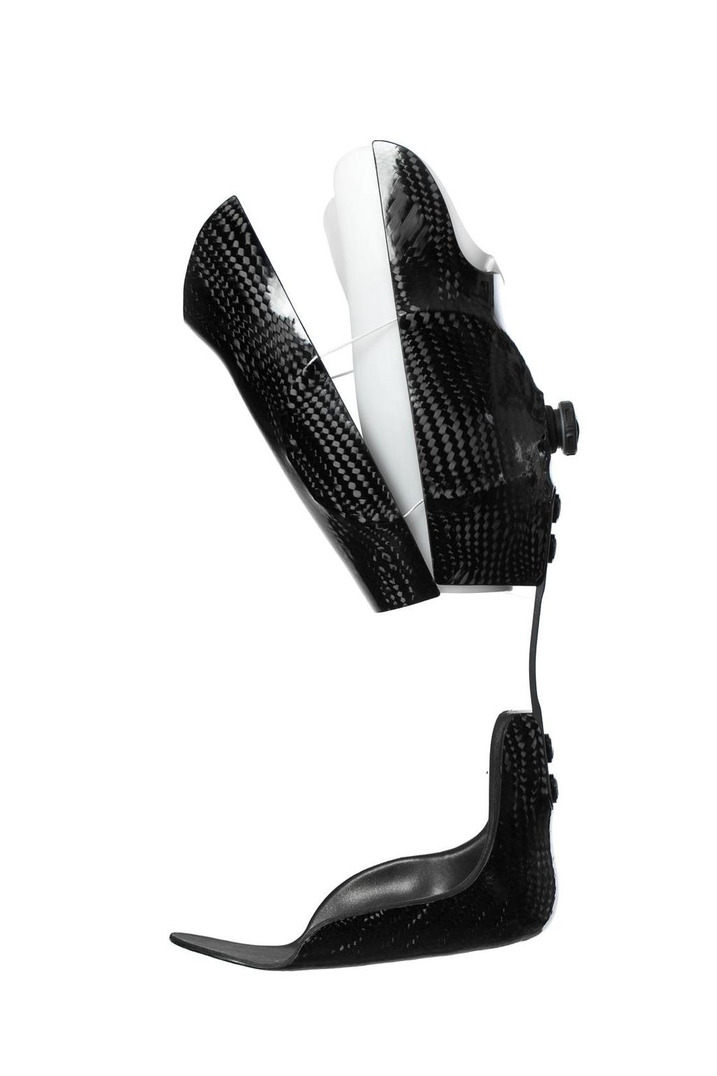
7 The PDE spring is not symmetrical. The bend is closer to the distal end of the spring. Shown here the distal location of the spring is to the right side. Note: The PDE logo sticker on the face of the spring will be in the upright readable position.
8 Assemble components in this configuration.

9 For fitting and attachment to the model the spring is assembled as shown. The white Delrin tooling must be included as this to maintain proper final alignment and space for the lamination materials.


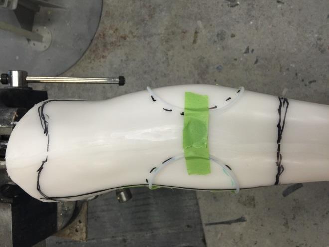
10 #2. Once the position has been determined mark the model with two marks. One mark will show the distal edge of the cuff and the other to show the proximal edge of the foot plate. #1. Position the spring setup on the posterior of the model keeping it proximal enough of the heel to allow clearance in shoes ~3 ½ to 3 ¾.


11 The Medial/lateral split for the proximal cuff should follow the coronal plane. Add the trim line mark up for cuff design.


12 Proposed trim lines of the cuff system as well as the proposed routing pathways for the closure system. Note: Keep Teflon tubing system away from proposed trim line edges by 1 if possible. Trim line adjustment may be needed during patient fitting.


13 Using a coarse sand paper abrade the Teflon housing so it will stay secure in the laminate. Note: This method displays the housing not using the supplied covered material tube braid. The easiest way to do this is by folding the sand paper and pulling the Teflon through.


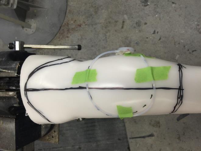
14 Tape Teflon tubing into position.


15 Teflon should be long enough to reach the center of the dial system. Plug Teflon ends with clay.


16 With the Teflon tubing in position using masking tape. Use Composite 1 adhesive to liberally glue down the exposed Teflon.


17 Wipe excess adhesive off of the routed tubing. The masking tape is a great place to wipe all excess that isn t needed.


18 Once the Composite1 adhesive has cured remove the masking tape. Use additional Composite1 adhesive and bond the open areas.


19 Wait 10 minutes for the adhesive to fully cure and bond to the Teflon tubing.
 assembly off of the plastic and safely put aside for future")
20 Using a blade or tip of a screwdriver carefully peel the cured tubing (complete) assembly off of the plastic and safely put aside for future placement.

21 Place the model on the table with the forefoot flat on the table. Using a square mark a vertical line for reference.

22 This reference mark is the ideal placement for the spring. In the event this mark is noticeably off center of the calf it is ok to alter it within a few degrees for aesthetics.
23 In a horizontal holder (vice) orient the model in a toe down position and set toe out. This will leave the line of progression in a vertical orientation.

24 Model in pipe holder with toe out set.

25 Fill both anchors with Composit1 adhesive. Note: Hollowed machined cavities face model.

26 Place assembly on model in alignment.

27 The face of the spring should be level.
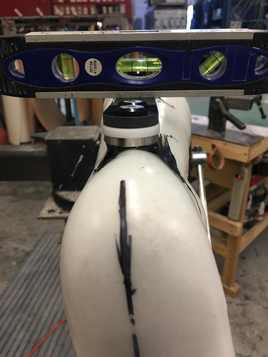
28


29 Fill any undercuts to minimize air issues during lamination.

30 Remove attachment screws from the PDE assembly leaving only the anchor plates bonded to model. Insert the set screws from the anchor kit into the anchor plate until they bottom out. Be sure the set screws are treated with a mold release of some type and after the installation the Allen wrench holes are filled with clay.
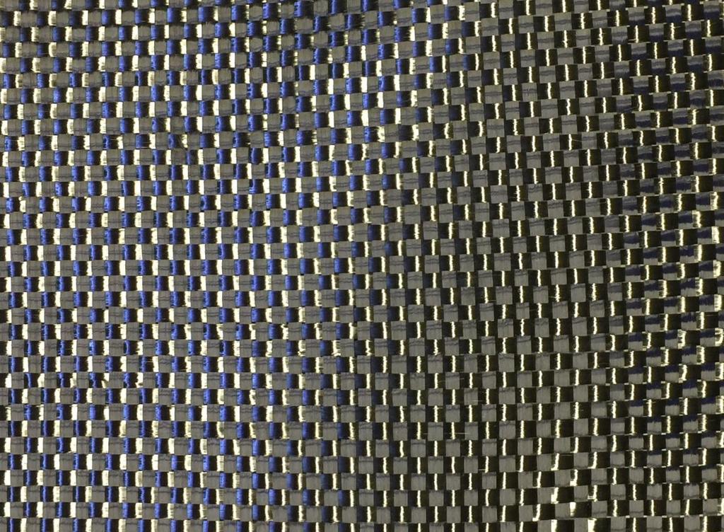
31 The layup process uses two materials 12K -/+ 45 Carbon Fiber Braid. 12K 0/90 Carbon Fiber Tape

32 Standard 12k weight 45 degree carbon tubular braid.

33 Fabtech CT6 12k weight 0/90 carbon tape. Note: Fabtech CT6 12K carbon tapes are available in 10ft and 50ft sections.
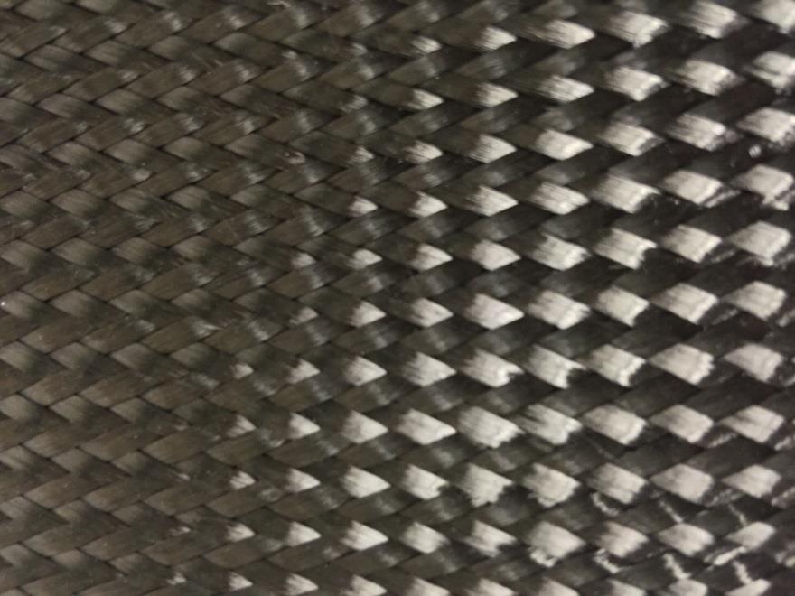

34 Fiber Orientation x /90
35 The correct amount of fiber must be used and it must be placed in the correct fiber orientation 45 degree x or 0/90 +. Alterations to this recommended minimum layup or materials substitutions will be at your own risk.

36 Cuff Section Material Lay-up
37 Proximal Cuff Material Lay-Up Schedule Apply the carbon in the following order using a light application of spray adhesive. 2ea layers 12K /45 degrees Carbon fiber braid. (Item# BCS6) 1ea layer of 12K 0/90 Carbon tape. (Item# CT6) **If using BOA Closure, add here between layers of 12K 0/90** 1ea layer of 12K 0/90 Carbon tape. (Item# CT6) 1ea layers 12K /45 degrees Carbon fiber braid. (Item# BCS6) 1ea layers 12K /45 degrees Carbon fiber braid over foot section and upper cuff. (See foot plate instructions as this is the final layer before lamination)

38 x Cover entire cuff section with 2ea 12k carbon braid oriented 45 degrees. Be sure and bring set screws through the spaces in the fabric. Ensure the layer is evenly glued down with no wrinkles gaps or bridging. Note: All materials are run over the attachment plates. Keep materials even and flat on plate surfaces.

39 + Add a layer of 0/90 carbon tape oriented as shown over anchor.

40 + Wrap 0/90 carbon tape around model to the midline. Trim any excess that goes past midline. If the 0/90 carbon tape did not extend to midline, cut an extra piece of carbon tape and add so it extends to midline.


41 + If using the BOA Closure System, add it now.

42 + Make sure the Teflon tubing and routing all line up and are in the correct position that was established earlier. Adjust if needed.

43 + Add a the second layer of 0/90 carbon tape and trim at midline

44 Form 12K 0/90 carbon tape over the BOA Closure System. Make sure it locks the system in well, as this will help hold it in position when laminating with resin.

45 Add the plastic tooling spacers. Note: Make sure lamination screws are exposed from underneath carbon materials.

46 Lamination set screws should look like this.

47 x Cover the proximal cuff in the final layer of 12K Carbon braid.

48 Foot Plate Material Lay-Up
49 Foot Plate Material Lay-Up Schedule Apply the carbon in the following order using a light application of spray adhesive. 2ea layers 12K /45 degrees Carbon fiber braid. (Item# BCS6) 3ea layer of 12K 0/90 Carbon tape. (Item# CT6) 1ea layers 12K /45 degrees Carbon fiber braid. (Item# BCS6) 1ea layers 12K /45 degrees Carbon fiber braid over foot section and upper cuff. This presentation is our recommended minimum Lay-up schedule. More material may be needed for heavy or highly active users.

50 x Cover the footplate in 2ea layers 12K carbon braid at 45 degree orientation.

51 Trim off excess material.

52 + Cover footplate with 3ea layers CT6 12K carbon tape in 0/90 orientation.

53 Cut fabric to contour around footplate.

54 Keep fiber orientation straight.

55 + Note: This is the minimum reinforcement at three layers. four layers are common with higher activity

56 x After all CT6-12K 0/90 carbon tape layers have been added cover with 1ea layer of 12K carbon braid at 45 degrees.


57 Place the lamination dummies on the model with the exposed set screws to hold it in position.

58 x Cover the entire model in a final layer of 12K carbon fiber braid at 45 degrees. Note: This is the last layer of 12K Carbon braid. Both the upper cuff and foot plate should have a total of 4ea layers now.

59 Split the final layer open by the ankle to get the fabric to lay down nicely.

60 Use tape or spray glue to secure loose ends.


61 Laminate with a minimum of 500grams of Epoxy resin. PN:RES1. Note: Epoxy resin is recommended for durability.
62 Special attention should be paid to the foot plate as it needs to remain flat and true for the device to function properly. When the resin has starting to gel it is recommended to roll the foot plate. This can be done with a section of prosthetic pylon or a aerosol can.
63 Once the resin has fully cured cutout and assembly can begin using standard techniques.

64

65
66

67 Additional Boa closure information can be found at the web addresses below.
TFC UPRIGHT FABRICATION MANUAL. from Fillauer LLC
 TFC UPRIGHT from Fillauer LLC FABRICATION MANUAL TFC UPRIGHT CONTOURING PROCESS FOR AFO 1. Determine calf band position, ankle joint placement, and upright clearances using a standard tracing. Place tracing
Big Oz. Rocket. User Guide V0313
 Big Oz Rocket User Guide 59824 V0313 Materials Included The Big Oz Rocket Kit should include the following materials. If something is missing, contact Customer Service at 800-358-4983. 20-ounce plastic
Patent pending. Product Manual
 Patent pending Product Manual Transradial Fabrication Instructions 1. Thermoform flexible inner socket. 2. Contour the attachment ring. The socket attachment ring can easily be contoured by hand or by
SGTalon s Enterprise-A Foamie Build Guide. SGTalon s. Enterprise. Enterprise--A. Assembly Instructions
 SGTalon s Enterprise SGTalon s Enterprise--A Enterprise Assembly Instructions Page 1 4-13-2013 SGTalon s Enterprise *******Recommended Hardware******** 2.6oz 250w Motor and Speed Control with 8x6 prop
Sentinel Armor Kit Assembly Guide
 1 Sentinel Armor Kit Assembly Guide 2 Thank you for purchasing the Mynock s Den Collection Sentinel Armor Kit by Vader s Vault. This guide will help you assemble your new kit, so be sure to keep it close
COMPOSITES LAB MANUAL
 COMPOSITES LAB MANUAL Version 1 Lab 3: Surface Preparation, Wet Layup, and Vacuum Bagging The original version of this manual was a one student senior design project written by Katherine White, the Composite
Mamba. Combat Wing Glider
 Mamba Combat Wing Glider Congratulations for your purchase of the Mamba radio-controlled combat glider! The Mamba is a very fast and agile glider and yet it can stay up in very light winds when built correctly.
Curium 19H Installation Instructions & Parts List
 Curium 19H Installation Instructions & Parts List Illustration Curium 19H Right Hand Page 1 of 15 01/07/2016 Revision 2.1 IMPORTANT This shower screen / enclosure must be installed by suitably qualified
Curium 19.4H Installation Instructions & Parts List
 Curium 19.4H Installation Instructions & Parts List Illustration Curium 19.4H Right Hand Page 1 of 21 30/06/2016 Revision 1.0 IMPORTANT This shower screen / enclosure must be installed by suitably qualified
Piper Cherokee /3 scale. Construction Manual
 Piper Cherokee 140 1/3 scale Construction Manual STAB CONSTRUCTION 1. Remove foam cores from cradle and place on flat surface. Inspect pieces before you epoxy halves together making sure leading and trailing
Cobra X Q Construction Tips Construction: Bel y pan
 Cobra X Q Construction Tips : The white plastic in this kit is high impact styrene. It can be painted with most types of coatings if light coats are applied this is necessary due to the thickness of the
The Ballistic Blaster Rocket Kit should contain the following items. If anything is missing, call Customer Service at
 Ballistic Blaster User Guide Materials Included The Ballistic Blaster Rocket Kit should contain the following items. If anything is missing, call Customer Service at 800-358-4983. Body tube, 6-1/2" long,
CertainTeed INSTALLATION GUIDE SIMTEK FENCE PRODUCTS. Fence Installation Guide 3', 4' & 6' High
 CertainTeed INSTALLATION GUIDE SIMTEK FENCE PRODUCTS Fence Installation Guide 3', 4' & 6' High INSTALLATION GUIDE These instructions are designed to assist both professional installers and do-it-yourselfers
ALLORA SWING PANEL INSTALLATION INSTRUCTIONS
 ALLORA SWING PANEL INSTALLATION INSTRUCTIONS Before Installation Please check that your Allora Swing Panel is undamaged SEQUENCE OF INSTALLATION These instructions are also available from the Athena website:
The Queen Quilter Professional Quilters Kit Frame
 The Queen Quilter Professional Quilters Kit Frame Assembly Instructions Table of Contents: Before you begin......................... Pg. 2 Wood parts............................. Pg. 3 Hardware..............................
Dubnium 11 Installation Instructions & Parts List
 Dubnium 11 Installation Instructions & Parts List Illustration Dubnium, H1 Handle Right Hand: Open Out Page 1 of 25 IMPORTANT This shower screen / enclosure must be installed by suitably qualified individuals.
Parts Identification
 We are excited to introduce the Model Aero Aqua Sport. This is an excellent sport flyer, equally at home flying from grass fields, water, or even snow! The unique V-tail gives the Aqua Sport a distinctive
Instructions - Stobel V2
 Instructions - Stobel V2 Congratulations on the purchase of your Stobel, a high end DLG-competition model from LE-composites. We hope you will be happy and successful. To ensure the optimum build we ask
LED Thin Frame Fixed Frame Screen User Guide
 LED Thin Frame Fixed Frame Screen User Guide INTRODUCTION INTRODUCTION WARNING - Sharp Edges This product may contain sharp edges, please handle with care. Protective gloves are recommended. WARNING -
U-bass Kit Assembly Instructions
 U-bass Kit Assembly Instructions Compiled by playubass.com This guide is built from the instructions found here: http://kalabrand.com/ubass-kit/index.html Tools Needed 5/8 (16 mm) Wrench 7/16 (~11 mm)
REVISION LIST CHAPTER 25: AFT WINDOWS. The following list of revisions will allow you to update the Legacy construction manual chapter listed above.
 REVISION LIST CHAPTER 25: The following list of revisions will allow you to update the Legacy construction manual chapter listed above. Under the Action column, R&R directs you to remove and replace the
Radon 07 Installation Instructions & Parts List
 Radon 07 Installation Instructions & Parts List Illustration Radon 07, H1 Handle Right Hand: Open Out 14/06/2016 Revision 1.1 Page 1 of 21 IMPORTANT This shower screen / enclosure must be installed by
Aeon CLR Series EDGE FREE CLR Fixed Frame Screen w/ StarBright CLR (Ceiling Light Rejecting ) Front Projection Material
 Front Projection Material") Aeon CLR Series EDGE FREE CLR Fixed Frame Screen w/ StarBright CLR (Ceiling Light Rejecting ) Front Projection Material User s Guide Product Description: The Aeon CLR Series is an ultra-short throw fixed
Aeon CLR Series EDGE FREE CLR Fixed Frame Screen w/ StarBright CLR (Ceiling Light Rejecting ) Front Projection Material User s Guide Product Description: The Aeon CLR Series is an ultra-short throw fixed
Elara NanoEdge Fixed Frame Screen User Guide
 Elara NanoEdge Fixed Frame Screen User Guide INTRODUCTION INTRODUCTION WARNING This product may contain sharp edges, please handle with care. Protective gloves are recommended. A minimum of two people
1Take the keel (3) and
 and") 1 The hull and the bridge 1Take the keel (3) and apply PVA wood glue in the second slot from the left: a toothpick may make it easier. Take care: the left end is the one that has a projection. THE HULL
1 The hull and the bridge 1Take the keel (3) and apply PVA wood glue in the second slot from the left: a toothpick may make it easier. Take care: the left end is the one that has a projection. THE HULL
ParkJet Builder s Manual
 ParkJet Builder s Manual Thank you for purchasing the ParkJet. The ParkJet is a profile ducted fan airplane that can be flown in a larger park. The ParkJet was initially designed by Scott Stoops and modified
Plans. Easy-to-Build Full-size Deluxe Murphy Bed Plan. For more plans, tools and hardware visit rockler.com
 Easy-to-Build Full-size Deluxe Murphy Bed Plan Build a full-size Deluxe Murphy Bed complete with decorative molding and matching side cabinets! Plans For more plans, tools and hardware visit rockler.com
Bath Accessory Installation
 Bath Accessory Installation Step 1 - Clean surface using a clean dry cloth or use rubbing alcohol to remove any residue (wax, grease, solvents). Allow to dry one hour. Caution! DO NOT use any household
Jeep Cherokee Door XJ Set Part # Revision J
 Jeep Cherokee 84-96 4 Door XJ Set Part # 10911 Revision J 6-5-06 Step 1: Prior to Installation: A) Fit: Verify the fit of the flares to vehicle. (Some filing, sanding, or cutting may be necessary to ensure
Thank you for your purchase of the Lee Ulinger, FoamtanaS, Yak-55, or Extra 330 3D Depron foam, Aerobatic airplane.
 Thank you for your purchase of the Lee Ulinger, FoamtanaS, Yak-55, or Extra 330 3D Depron foam, Aerobatic airplane. Tools you will need to build Recommended additional items: #11 hobby knife Motor: Hacker
Premium Light Filtering Sheer Shade
 Premium Light Filtering Sheer Shade Installation Instructions Email: customerservice@blindster.com Call us: (888) 256-8672 Mon - Fri 8am - 7pm (CT) Congratulations on purchasing a Premium Light Filtering
Seamed Undermount Bowls
 CUTOUT TEMPLATES MAKING CUTOUT TEMPLATES 7.1 CUTOUT TEMPLATES The use of an accurate template is one of the most essential elements to the successful completion of a cutout in Corian. For the completion
Step by Step Wing Bagging
 Step by Step Wing Bagging By Evan Shaw 073 589 9339 evanevshaw@gmail.com Preparing the Leading Edge 1. Cut cores. (Cutting of wing cores is covered in another article elsewhere) 2. Sand the LE to a nice
Super Sky Surfer 2000 Assembly Instructions
 Super Sky Surfer 2000 Assembly Instructions Note: Plug and Play version of the Sky Surfer comes with fuselage pre-glued and motor/servos installed. If you wish to route antennas or wires through the tail,
B A T H R O O M G L A S S
 mistley B A T H R O O M G L A S S vaug16 Page 2 Thank you for purchasing this Trinity shower screen. Please study these instructions carefully before assembly and installation and check all supplied parts
CONTENTS OVERVIEW. For a complete set of CAD drawing details, please visit LaminatorsInc.com. 1 Essential Equipment. 1 Essential Supplies
 LaminatorsInc.com CONTENTS 1 Essential Equipment 1 Essential Supplies 2 Panel Preparation 4 Panel Extrusion Preparation 5 Panel Assembly 6 Wall Sheathing Preparation (Over Plywood) 6 Wall Sheathing Preparation
1/6 PA-25 PAWNEE. *Specifications are subject to change without notice.*
 1/6 PA-25 PAWNEE INSTRUCTION MANUAL [ A335 Kit ] Wing Span : 72 in / 1830 mm Wing Area : 736 sq in / 47.5 sq dm Flying Weight : 6.6 lbs / 3000 g Fuselage Length : 48 in / 1220 mm Requires : "Glow Power"
Tripanel Marine Technical Bulletin
 Tripanel Marine Technical Bulletin Figure 1 Cabinet joints can be accomplished by four methods: a) rabbet one panel to the proper thickness of joining panel and epoxy joint b) dado to thickness of joining
10. Wing prep and subassembly
 Date Section Objective: Construct and fabricate the sub-assemblies of the wing panel. Required Parts: Wing left 11gal PN104-300, Wing right 1gal PN104-400, Wing left 15 gal option PN104-322, Wing right
3555 Scarlet Oak Blvd. St. Louis, MO FAX:
 I. INSTALLATION TOOLS A. Utility Knife B. Scissors C. Sand Paper and/or File D. Fabric Tucking Tools (available from Fabric Wall) 1. Rocker Tool 2. Flat Blade with round edge 3. Bent Blade with round edge
TREX TRANSCEND RAILING
 RAILING NOTES:» RAILINGS ARE DESIGNED TO BE INSTALLED OVER THE DECKING FRAME OR ON INSIDE OF RIM JOIST. NOTCHING OF PRESSURE-TREATED POSTS OR POSTS INSTALLED ON OUTSIDE OF RIM JOIST IS NOT ALLOWED.» All
SPUNKY ASSEMBLY MANUAL
 SPUNKY ASSEMBLY MANUAL Please read the tips section at the back of this manual regarding the use of laser cut parts. The proper removal and preparation of these parts is important. When laser cut, some
1999 Combat Wing Trick R/C Products LLC 938 Victoria Ave. Venice, California 90291
 1999 Combat Wing Wing Span 48" Wing Area 2.83 SqFt Airfoil Zagi 99 Weight 18/23 oz Loading 7 oz/sq.ft Radio 2 channel or mixer Speed Range Wind: 6 to 45 mph Visit: ZAGI.com Email: Zod@Zagi.com Voice: (310)
3Insert the second rod no. 4
 Yamato: Step-by-step 37 The stern block and searchlight control towers a b c d e f Recommended tools and materials Wood glue Sandpaper (no. 800 grain) Metal file Putty Craft knife For metal: Super Glue
Hobby Lobby Zip Supplementary instructions Please refer to the included drawings while using these assembly instructions
 Materials needed: 15 or 30 minute epoxy Medium CA Masking tape Scotch tape Servo Tape Wax paper Tools Needed: Pencil or marker Flat building surface Hobby knife or razor blade 7/64" or 3mm drill bit 3/16"
Aeon AcousticPro UHD Series
 Aeon AcousticPro UHD Series EDGE FREE Fixed Frame Sound Transparent Projection Screen User s Guide Product Description: The Aeon AcousticPro UHD Series is a fixed frame projection screen that uses Elite
Corvus Racer CC
 Corvus Racer 540 35CC Item No:L-G035008 Specifications Wing Span Length Wing Area Flying Weight Glow Gasoline Electric Radio mm mm 1200sq in (77.4sqdm) 9.9-12lbs(4.5-5.5kg) 91-1.20(2C) 1.10-1.40(4C) 20-40cc
Jeep Cherokee 4-Door XJ Set Part # Rev
 Jeep Cherokee 4-Door XJ Set Part # 10911 Rev-14 04-05-10 Step 1: Prior to Installation: A) Bushwacker only approves installing the flares according to these written instructions with the hardware provided.
(Build Instructions)
") (Build Instructions) Specifications * Wingspan: 58cm * Length: 50cm * Flying Weight: 59 grams * Channels: 3 (Rudder Elevator Throttle) * Suggested Receiver: 4Ch Micro * Motor: 8mm GearDrive * Prop: GWS
(Build Instructions) Specifications * Wingspan: 58cm * Length: 50cm * Flying Weight: 59 grams * Channels: 3 (Rudder Elevator Throttle) * Suggested Receiver: 4Ch Micro * Motor: 8mm GearDrive * Prop: GWS
Additional Parts List:
 THE TIME MACHINE Additional Parts List: In addition to the cast resin parts enclosed in this kit, there should also be a plastic bag containing the following items needed to complete your time machine
THE ROGUE TM FUNSLIDE TM
 THE ROGUE TM FUNSLIDE TM ASSEMBLY AND INSTALLATION INSTRUCTIONS * * C A U T I O N * * S.R. SMITH ROGUE TM FUNSLIDES TM ARE MANUFACTURED FOR INSTALLATION AND USE ON RESIDENTIAL INGROUND POOLS ONLY. ROGUE
Wall Panel Installation Instructions
 Panel Installation Instructions Demolition - Common Tools Needed Reciprocating Saw Allen Wrench Set Hole Saw Set Pry Bar Dust Pan and Brush Putty Knife / Scraper Hex Bit Socket Set All Necessary Safety
Frameless Inline Door QCI5250
 INSTALLATION INSTRUCTIONS Frameless Inline Door QCI5250 FRAMELESS PANEL / DOOR / PANEL QCI0249 REV. 3 Page 1 Certified 10/12/12 Parts List with pivot hinges *Quantities may vary. QCI0249 REV. 3 Page 2
Stream NXT - assembly instructions
 Stream NXT - assembly instructions Recommended settings CG (measured from root leading edge): Speed/launch camber (+down, near the wing root): Cruise camber (+down, near the wing root): Thermal camber
C-Bot. User Guide. Cautionary and Warning Statements
 C-Bot User Guide Cautionary and Warning Statements This kit is designed and intended for educational purposes only. Use only under the direct supervision of an adult who has read and understood the instructions
Instructions for Installation on a Pitched Roof LIGHTWAY optical tube LW 260, LW 320, LW 520, LW 760
 Lightway, s.r.o. Registered office: Ledvinova 1714, 149 00 Praha 4 Offices: Za Humny 1054/4a, 161 00 Praha 6 tel.: 235 300 694, fax: 235 300 218 Company ID No.: 63669366, Tax ID No.: CZ63669366 Bank: KB
Building Tips This model can be built using the following types of adhesives:
 Page 1 Building Tips This model can be built using the following types of adhesives: Epoxy (with or without microballons) Odorless cyanoacrylate (CA) with accelerator UHU Creativ for Styrofoam (or UHU
Written By: Brook Drumm
 Simple 1401 Assembly For kits produced between 1/15/14-6/1/14. This guide is for kits with the Fan Shroud. Instructions for metal and wood extruder (and bed) included below. Written By: Brook Drumm TOOLS:
SE5a Instrument Board part 2 - rev 1.1
 SE5a Instrument Board part 2 - rev 1.1 Fuel (Petrol) Valve This valve uses two circular name plates, eight brass screws, one black plastic base, copper wire and two black plastic risers. You can pick any
Making your Rudder Cassette
 Making your Rudder Cassette A list of the stuff you ll need The row of materials below is laid out in the order of application. The foam blank shown on the right is available from Bob at www.flyingfoam.com
Making a Cement Upper Molding Surface for Compression Molding of Shape&Roll Prosthetic Foot Cores
 Making a Cement Upper Molding Surface for Compression Molding of Shape&Roll Prosthetic Foot Cores Andrew Hansen, PhD Steven Steer, MS Kerice Tucker Elizabeth Klodd Craig Heckathorne, MS Northwestern University
Depending on the size you ordered you will have either 5 Foot sections which will build the 10 Foot frame or 6 Foot sections which will build the 12
 XL Quilting Frame 1 Depending on the size you ordered you will have either 5 Foot sections which will build the 10 Foot frame or 6 Foot sections which will build the 12 Foot frame Printed 2 June 2014 Updated
Bolt-On/Rugged Fender Flares Toyota Tundra (14-ON) Important: Please read instructions entirely before installing this product.
 Important: Please read instructions entirely before installing this product.") Important: Please read instructions entirely before installing this product. Hardware Included QTY Hardware Included QTY Bolt Kit Included QTY Extrusion 28.0 ft Short Screw 18 Nuts 42 Alcohol Wipe 4 Long
Important: Please read instructions entirely before installing this product. Hardware Included QTY Hardware Included QTY Bolt Kit Included QTY Extrusion 28.0 ft Short Screw 18 Nuts 42 Alcohol Wipe 4 Long
R2C Performance Products 7550 Industrial Drive Forest Park, IL Ph: (708)
") Congratulations on your purchase of the finest Sprint Car Filter and stack sealing system available. This system has been designed for unparalleled ease of assembly, disassembly and cleaning while providing
Congratulations on your purchase of the finest Sprint Car Filter and stack sealing system available. This system has been designed for unparalleled ease of assembly, disassembly and cleaning while providing
Slide the stock rubber tank mount caps onto the ends of the CS-1 tank mount:
 RYCA CS-1 BODY PARTS INSTALLATION GUIDE [The CS-1 installation guides should be used as supplements to the videos found on our Youtube Channel. There is no strict order to the build process, but it is
From "American Woodturner" the Journal of the American Association of Woodturners, April 2015, vol 30, no 2 - CUSTOM - TOOL HANDLES
 From "American Woodturner" the Journal of the American Association of Woodturners, April 2015, vol 30, no 2 - CUSTOM - TOOL HANDLES Carl Ford I have found most commercially available tool handles uncomfortable
Gallium 03 Installation Instructions & Parts List
 Gallium 03 Installation Instructions & Parts List Illustration Gallium 03, H1 Handle Left Hand: Open Out 04/05/2016 Revision 1.1 Page 1 of 19 IMPORTANT This shower screen / enclosure must be installed
The Phoenix. Professional Quilting Frame. Copyright January 1, 2016 Jim M. Bagley, GraceWood, Inc (Reproduction Prohibited) Version 2.
 Version 2.") The Phoenix Professional Quilting Frame Copyright January 1, 2016 Jim M. Bagley, GraceWood, Inc (Reproduction Prohibited) Version 2.1 1 The Phoenix Professional Quilting Frame Parts List Box 1...3 Box
The Phoenix Professional Quilting Frame Copyright January 1, 2016 Jim M. Bagley, GraceWood, Inc (Reproduction Prohibited) Version 2.1 1 The Phoenix Professional Quilting Frame Parts List Box 1...3 Box
FLITZEBOGEN-2 Assembly instructions
 FLITZEBOGEN-2 Assembly instructions Trim the end of the fuselage to the length of 925mm from the nose. Be careful to avoid splitting the carbon fibers. Sand the base of the stab mount in preparation for
6mmFlyRC.com Super Bandit Assembly Instructions
 Assembly Instructions Start the assembly with forward fuselage. Lay the two fuselage sides down on a flat surface and glue the foam corner doublers to the locations shown on the plans. Make sure to make
Standard Kit #1 (3-way switch)
") Standard Kit #1 (3-way switch) Please Read All Instructions Before Beginning. Tools you will need: Soldering Iron (35 watt preferably) Solder Wet Sponge Wire Clippers 3/8 Drill Bit 1/4 Drill Bit Variable
Standard Kit #1 (3-way switch) Please Read All Instructions Before Beginning. Tools you will need: Soldering Iron (35 watt preferably) Solder Wet Sponge Wire Clippers 3/8 Drill Bit 1/4 Drill Bit Variable
Zeon PDF Driver Trial
 Opus retro-fit tray assembly kit Features: CNC machined G10/FR4 fiberglass tray assembly. CNC machined G10/FR4 fiberglass replacement control horns. Milled aluminum servo mount system Servo mount is pre-drilled
F-F-Fiddle Assembly Instructions
 F-F-Fiddle Assembly Instructions Bout Bridge Neck Machine Heads/Tuners Truss Rod Strings An open-source FFF 3d-printable electric violin. 1. Assemble materials 5 3 8 1 9,10, 11 7 4 2 6 PARTS 1. Bout part
Deluxe Exterior Solar Shades
 Deluxe Exterior Solar Shades Installation Instructions Email: customerservice@blindster.com Call us: (888) 256-8672 Mon - Fri 8am - 7pm (CT) Thank you for purchasing Deluxe Exterior Solar Shades from Blindster.
RESolution V2 Manual
 RESolution V2 Manual Note for the German Manual: Yellow Bottle thick CA Pink Bottle Med CA Blue tube 5 minute Epoxy Green tube 90 Minute Epoxy Construction of the Fuselage Step 1: Cover the plan with a
Ford F150 Rear Flares Set Part # Revision
 Ford F150 Rear Flares Set Part # 20074 Revision 1 04-01-09 Step 1: Prior to Installation: A) Bushwacker only approves installing the flares according to these written instructions with the hardware provided.
Installation Instructions
 Aspex Digitally Printed Wall Art PL PREMIUM HEAVY DUTY ADHESIVE ASPEX WALL ART DOUBLE SIDED FOAM TAPE Installation of Aspex Digitally Printed Wall Art with Foam Tape and PL Premium Adhesive. Maximum size
Standard Kit #1 (5-way switch)
") Standard Kit #1 (5-way switch) Please Read All Instructions Before Beginning. Tools you will need: Soldering Iron (35 watt preferably) Solder Wet Sponge Wire Clippers 3/8 Drill Bit 1/4 Drill Bit Variable
Standard Kit #1 (5-way switch) Please Read All Instructions Before Beginning. Tools you will need: Soldering Iron (35 watt preferably) Solder Wet Sponge Wire Clippers 3/8 Drill Bit 1/4 Drill Bit Variable
Robert Bosch GmbH. Wall organiser
 Wall organiser The organisational talent Wall organiser Say goodbye to messiness! The wall organiser is the ideal place to store everything that tends to lie around. 1 Introduction Wardrobes, drawers and
FIXED PANEL SLIDER QCI5241
 INSTALLATION INSTRUCTIONS FIXED PANEL SLIDER QCI5241 FRAMELESS PANEL / DOOR / PANEL FRAMELESS DOOR / PANEL QCI5241 REV. 0 Page 1 Certified 06/16/2016 Parts List *Quantities may vary QCI5241 REV. 0 Page
Adhesive Application & Laminating System
 U S E R S G U I D E Adhesive Application & Laminating System The XM2500 is an economical and easy to use document finishing system. This versatile and non-electric system has been designed to laminate
The NYU Transparent Socket Fabrication Procedure 1
 The NYU Transparent Socket Fabrication Procedure 1 Thomas Grille, 2 Ronald Lipskin, 3 and Richard Hanak It has been recognized for a long time that a transparent socket that could be made to fit the stump
INSTALLATION GUIDE DUOFUSE SLAT WALL SYSTEM
 06/2013 ENG 1 INSTALLATION GUIDE DUOFUSE SLAT WALL SYSTEM The Duofuse wood composite slat wall system is much more durable than wooden fences, and correct installation is necessary to enjoy the fences
Nanton Grain Mill Assembly
 ( 1 ) Nanton Grain Mill Assembly Locate package for assembling storage building. These are cut from 1/8 masonite. Inspect and lightly sand edges where it will be bonded. Use white glue or CA glue to bond.
5If the protruding part is. 6Place 1 as is shown in the. 7Place what was assembled
 Yamato: Step-by-step 49 The base of the bridge and strakes a c b d a Base of the bridge b Base of the bridge c Base of the bridge d Strakes x 10 THE BASE OF THE BRIDGE 1Smooth 1 to 3, first using the metal
i-limb TM digits Component Assembly Guide
 i-limb TM digits Component Assembly Guide This document provides instruction for prosthetists in the assembly of i-limb digits components necessary in the fabrication of i-limb digits prostheses. The instructions
Aerospace Speciality Products
 Specifications:! Length: 18.75"/47.6 cm! Diameter: 0.98"/24.9 mm! Weight: 1.5 oz/44 gm! Streamer Recovery! Recommended Engines:!! A8-3; B4-4; B6-4; C6-5! Skill Level: Beginner This is a model rocket kit
ICECAST MSS TOOL KIT ANATOMY ICECAST MSS TOOL KIT COMPACT ÖSSUR POST-OP SOLUTIONS
 ICECAST MSS TOOL KIT ANATOMY Icecast Anatomy represents a further development of the pressurecasting concept. Contour Cell shaping-chambers positioned over soft tissue areas can be inflated independently
Xyron Professional 2500 Laminating System
 Xyron Professional 2500 Laminating System Instruction Manual Provided By http://www.mybinding.com http://www.mybindingblog.com U S E R S G U I D E 2500 Adhesive Application & Laminating System The XM2500
Model 209 Fireback Replacement
 Model 209 Fireback Replacement Please read all the instructions before you begin the procedure. Confirm that you have all the necessary tools and materials. If you have any questions, technical support
CAL-K1 Self-build guitar kit UK Version 1.0
 CAL-K1 Self-build guitar kit 174.460UK Version 1.0 Thank you for buying the CAL-K1 kit. All the wood, hardware and electrical components of a Chord CAL93 guitar are contained in this package. Please read
Handrail H Series. Product Installation. Instructions. Installation Instructions For. Wall Mounted and Freestanding Round Handrails
 Product Installation Installation Instructions For Instructions Handrail H Series Installation Instructions for Wall Mounted and Freestanding Round Handrails Step Nosing F Series Concrete and Timber Step
Monaco Installation Guide - Surface Profiles - vjun16
 1 Thank you for purchasing this Monaco shower screen. Please study these instructions carefully before assembly and installation. Checking of Parts Parts are listed at the beginning of this guide. Please
MODERN PERGOLA INSTALLATION GUIDE. When only the best will do.
 MODERN PERGOLA INSTALLATION GUIDE When only the best will do. TOOLS LIST Drill(s) 3/8" Magnetic Driver (s) 12" Drill Extension #2 Square Drive bit for Drill or Driver Level Tape Measure Hammer Drill if
Showpiece Cabinet Integrated Stand For 32" - 52" LCD HDTV
 Showpiece Cabinet Integrated Stand For 32" - 52" LCD HDTV Installation and Assembly Instructions 2009 Incredible Technologies Inc. Version 0109 Showpiece Cabinet Integrated Stand for 32" - 52" LCD HDTV
Daige Quikmount 4 Operating Guide
 Daige Quikmount 4 Operating Guide Save time and money... If you read this operating guide, follow each step exactly, then you will laminate or mount successfully. If you don t read it, or do not follow
Owner s Manual. Bass-Guitar Kit J-Style
 Owner s Manual Bass-Guitar Kit J-Style Contents Introduction... 3 Body finish... 4 Neck finish... 4 Assembling of tuners... 5 Neck... 6 Wiring... 6 Bridge assembly... 8 Strap buttons... 8 Setting up...
Installation Guide Acoustic Wall Panel
 Installation Guide Acoustic Wall Panel Contents Preface 2 Adhesive Method 3 Fast Mount Method 4 Adhesive Method 5 Direct Fix Method 6 Magnet Method 7 Preface Wall Preparation Before beginning the installation
Installation Guide. Welcome to the Pro Box Installation Guide
 23112 Mariposa, CA 90502 USA T 310.530.1383 F 310.325.6409 info@proboxfinsystems.com Welcome to the Pro Box Installation Guide This guide goes step by step through the entire installation process. Each
September 10, 2009 Page 1 PRODUCT DESCRIPTION PRODUCT FEATURES
 September 10, 2009 Page 1 PRODUCT FEATURES BASIC USES/RELATED USES Interior decorative tile. Architectural tile for decorative wall surfaces, backsplashes and other applications. Custom architectural and