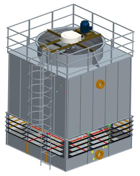
INSTALLATION MANUAL (MCR L) MCR SERIES COUNTER FLOW LOW NOISE TYPE COOLING TOWER
|
|
|
- Chastity Sutton
- 6 years ago
- Views:
Transcription
1 COOLING TOWER INSTALLATION MANUAL (MCR L) MCR SERIES COUNTER FLOW LOW NOISE TYPE COOLING TOWER
2
3 1. Installation Preparation 1.1 Preparation 1.2 Confirmation 1.3 Storage Content 2. Installation Step 2.01 Cold water basin (Attention: waterproof procedure) 2.02 Air inlet support 2.03 Acoustic mat with mesh & support, infill main support and make up water accessary 2.04 Side panel (Attention: waterproof procedure) 2.05 Infill support,infill,semi-circular tube 2.06 Distribution system and nozzle 2.07 Drift eliminator and upper catwalk 2.08 Fan stack 2.09 Transmission system 2.10 Handrail,safety cage,ladder,louvre
4 1. Installation Preparation 1.1 Preparation In order to achieve convenient and quick installation, please prepare in accordance with the following instructions: Carefully refer to the installation diagrams, the list of packing, and the list of screws so as to examine and analyze the structure and components of the cooling tower, and understand the installation steps and procedures Standby tools Before the installation, please prepare for the following tools, and determine the number of staff needed according to the size, quantity and work period of the cooling tower, and determine the type, quantity and time needed for installing the machinery according to the position of installation, and then estimate the installation cost. Basic tools needed: Spanners (Open-mouth, plum blossom, or casing) 6 x 8 8 x x x x x x x 24 Flexible Spanner Inner Hexagon Spanner Pipe Wrench Trestle Ladder 2000m (H), or 3000m (H)
5 Prying Bar M10, M12 Horizontal Pipeline 1 pc (20-30m) Horizontal Ruler 2 Units Supporting Wire 2 Units Straight Screwdriver 6 x x 150 Cross Screwdriver #1 #3 Plier 175 or 200 Hammer 2 Pieces Mallet 2 Pieces Iron Bars 900 Screw Saw 1 pc Hand Saw 1 pc Steel Measuring Tape 20m Hand Electric Drill 10mm Drill Adjusting pad (Several) 60mm x 60mm, Thickness 2mm, 3mm, 1mm Nylon rope 8m - 10m Other electric tools, electrical welding, fireproof apparatuses, safety equipment Greasing oil Sandpape 1.2 Installation Site Confirmation Check Check whether the foundation meets the installation requirements. Check and survey the situations with horizontal pipe and scroll rule according to the dimension and requirements of the foundation diagram as provided by Mesan Company. If the error is relatively large, please make the preparation so as to realize the installation requirements for a smooth installation. Various footings of the cooling tower shall be buried with an error which is no larger than 5mm, and the central diagonal is not larger than 3mm. See Figure (I) Check whether the quantity of all components is correct according to the list of packing. Sort

6 and place the components according to the installation map, installation manual, and the installation sequence, and store them according to the requirements, which will provide quick, accurate useful conditions for the installation Determine the specific installation direction according to the requirements of the client and the water intake and outlet positions of the cooling tower Fabricate according to the above mentioned requirements if there is steel structure foundation. 1.3 Storage See Figure (I) Filling materials (rubber pad) The filling materials shall be placed in cool and dry places, keep away from overweight on the top and the direct sunshine under the sun, in avoidance of over early transformation and aging Electric motor (motor) and fan The electrical motor and fan shall be placed in cool, ventilating and safe places, in avoidance of external rusting and damaged insulation. Pay special attention so as not to lose.
7 1.3.3 Belt Reducer Doc. No.: doc-mcr l Belt reducer shall be placed in cool, ventilating and safe places, in avoidance of rusting or loss. The belt reducer shall stand and avoid flat laying, in avoidance of crashing or transformation by the heavy matters Rubber mortar, fiber The rubber mortar and fiber shall be placed in dry, cool and ventilating places, in avoidance of direct strong sunshine so as not to become void Fiber Components The fiber components shall be placed separately. Don t place other hardware items on the top so as not to be damaged or transformed. Stack the items properly according to different shapes Hardware Items Hardware items shall be placed according to different dimension separately so as to count the quantity, sort by type, and transport easily. It is better to place according to the sequence of installation. 2. Installation Step Install the cooling tower according to the following procedure 2.01 Cold water basin 1) Read carefully the waterproof procedure(see figure 2)before install the cold water basin 2)Connect all the basin components by hand first BUT DO NOT TIGHTEN UP THE. BOLTS & NUTS 100%. Some tolerance needed to be minor adjusted on the basin. Use level ruler to check horizontal level on all sides of basin. Tolerance more than 3mm, sheet metal spacer should be added under the tower support. 3) Check the basin is regularly by using nylon string, tape to measure 4 angles of the basin. Tolerance between the diagonal length should not more than 3mm. Tighten all the bolts and nuts and check the horizontal level again within the tolerance.
8 Side view of 2 pcs cold water basin sections Basin section IMPORTANT :Reserve 10mm spacing for silicone Basin section nuts washes Bolt 1 Gasket each side on basin section 1 Gasket each side on basin section Gasket

9 basin silicone basin gasket

10 gasket Doc. No.: doc-mcr l
 2.")
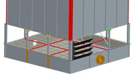
11 silicone 006 holes for ladder Air inlet support Figure 2 1. Attention to put gaskets on basin before install the air inlet support.(see figure 3a & b) 2. Put gaskets in between washes when tighten up bolts & nuts

12 (see figure 3a)
13 Figure 3b holes for infill main support bracing holes for infill main support 2.03 Acoustic mat with mesh & support, infill main support and make up water accessary 1) When install acoustic mat support and infill main support, gaskets must be put in between washes when tightened up bolts & nuts 2) After put acoustic mat with mesh on acoustic mat support, use nylon tie to tie up acoustic
 Doc. No.")
14 mat one another 3) Rubber gasket must be put when install debris strainer. (see figure 4) Doc. No.: doc-mcr l

15
 2) Place the panels on ground in order, and pay attention on some holes on panels for installing different parts.")
16 Figure Side panel 1) Install 4 pieces of panel middle post on four corners. (see figure 5) 2) Place the panels on ground in order, and pay attention on some holes on panels for installing different parts. (see Figure 7a & b) 3) Attention on waterproof procedure when installing panels (see Figure 6) 4) Install 3 side panels only at the beginning and left 1 side for installing infill.(see Figure 8)

17 033 Figure 5
18 a section of panel reserve 10mm spacing for silicone a section of panel nuts washes bolts gasket gasket a section of panel silicone a section of panel Figure 6
19 holes for fan stack holes for calkwalk holes for fan stack Figure 7a
20 holes for fan stack holes for fan stack holes for fan stack holes for eliminator support

21 holes for distribution pipes holes for infill support Figure 7b
22 Figure Infill support, infill and semi-circular tube 1) Gasket must be put when install infill support (see figure 9) 2) Infill is combined of 4 layers with 2 different height, 220mm & 330mm. Pls follow the sequence from the bottom to the top,330mm,330mm,220mm,220mm, and each layer of infill have to be perpendicular each other.(see figure 10a & b) 3) use plastic fastener to install the semi-circular tube. (see figure 11) infill support a section of panel nut washes bolt gasket gasket Figure 9

23 1st layer High 330mm

24 2nd layer High 330mm 3rd layer High 220mm
25 4th layer High 220mm Figure 10a

26 075,076 Figure 10b

27 Figure , , Distribution system and nozzle Attention: nozzle types and position must be installed correctly, or it may result tower capability drop.(see figure15) 1) Install the distribution pipe support on the panel, and gaskets must be put in between washes when tighten up the bolts & nuts. (see Figure 12)
28 2) Install the nozzles on the distribution pipe; gasket must be put on nozzle; (see Figure 13) spray board installed on 4 corners; install the sub-distribution pipe with nozzle onto the main distribution pipe; using half lock to fix sub-distribution pipe on the pipe support against the panel. (see figure 14) nut gasket washes bolt distribution pipe support a section of panel


29 Figure Figure13

30 067 Figure 14 Attention: pls follow the following install the different type of nozzles accordingly, or it may result tower capability drop. Nozzle types : 1.Yellow-crossing spray 2. Black-half spray 3.Red-full spray
31 half spray 064 full spray 063 spray board 067 crossing spray 065 gasket Figure 15

32

33 Figure 14
 3)Gasket must be put in between washes when install the catwalk onto the panel.")
34 2.07 Drift eliminator and upper catwalk 1)Put the eliminator on the distribution pipes, then install the eliminator holder pipes on the panel (see figure 16). Gasket must be put in between washes when tighten up the screws (see figure 15) 3)Gasket must be put in between washes when install the catwalk onto the panel. 4)Install the fan stack support onto the panel. 077,078

35 parts to be connected panel nut washes bolt Figure 15 gasket gasket

36 Figure 16 Doc. No.: doc-mcr l
Than tighten up those bolts & nuts in between fan stack one and other.")
37 2.08 Fan stack 1)Tighten up those bolts & nuts in between panels and fan stack. 2)Than tighten up those bolts & nuts in between fan stack one and other. 3) Pay attention those holes for motor support (see figure 18) holes of ladder Figure 17

38 马达辅架孔 holes for motor support holes for motor 马达主架孔 main support Figure 18
 Install the fan hub onto the speed reducer (please refer to Fan Installation), then install the blades.")
39 2.09 Transmission system 1) Put & fix the motor main support onto the fan stack, but do not tighten up the screws 100%. 2) Install the speed reducer on the center of motor support. 3) Install the fan hub onto the speed reducer (please refer to Fan Installation), then install the blades. After checked the tip clearance if they are even by rotating the blades, tighten up all the screws in between motor support and fan stack. 4)Install the motor and put the belts onto small and larger pulley of the V-belt reducer, then adjust the V-belt tension by tighten or loosen the long screws See Figure Suitable tension is V-belt distortion approximately 10mm by hand pressing in the middle of the position between small and large pulley, and then fasten the connection bolts and nuts between the motor support and the main support. Note: After running the tower a week, check the V-belt and adjust the tension once again.
 2)Install safety cage and ladder (see figure 20) 3)Install the louvre onto the frame before install it onto the air take sections (see figure")
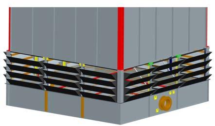
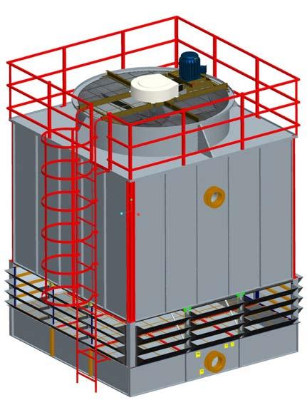
40 Handrail, safety cage, ladder, louvre 1)Handrail post on 4 corners are right angle steel, and the rest are square hollow. (see figure 19) 2)Install safety cage and ladder (see figure 20) 3)Install the louvre onto the frame before install it onto the air take sections (see figure
41 21) holes for ladder Figure 19
42

43 Figure , Figure 21
44
45
Assembly Instructions
 Laminate/Phenolic & 1 Pc Butcherblock Tops Before you begin, please make sure all parts and proper quantities are included. (See on next page) Any parts damaged during shipment must be reported within
installation instructions
 installation instructions Easi-Plan WC Frame 820mm with Dual Flush Cistern ref: EPWC-05-1005 Easi-Plan WC Frame 980mm with Dual Flush Cistern ref: EPWC-05-1505 EASI-PLAN installation instructions Parts
Important Notice. caution: Use proper lifting equipment and correct procedures to avoid injury.
 Integrity. Partnership. Quality. COMMERCIAL DOOR INSTALLATION INSTRUCTIONS SERIES 1900, 1950, 2000, 2250, 2500, 2750 Important Notice In the following text, the word: Warning: Indicates that serious injury
Assembly Instructions
 18' W x 10' H or 12' H Peak Style Frame Assembly Assembly Instructions Before you start: 2+ individuals recommended for assembly, approximate time 3 hours. Recommended tools: Power Drill, Safety Glasses,
Installation Instructions for Vista Air Vertically Folding Walls
 Installation Instructions for Vista Air Vertically Folding Walls Use these instructions in conjunction with your shop drawings to see the specifics that are particular to the model you are installing.
Included in Hardware Kit. Jeep Cut-Out Fender Flare Set of 4 Set Part # Rev STEP 1 PRIOR TO INSTALLATION
 Jeep Cut-Out Fender Flare Set of 4 Set Part #10926-07 Rev-01 09-11-12 STEP 1 PRIOR TO INSTALLATION A) Bushwacker only approves installing the flares according to these written instructions with the hardware
400A 40113V, 401A 40120V, & 401AL 40120VL ALUMINUM VERTICAL 4000 LB LIFT INCLUDES SCREW LEG ASSEMBLY INSTRUCTIONS
 12/11/07 PAGE 1 OF 12 400A 40113V, 401A 40120V, & 401AL 40120VL ALUMINUM VERTICAL 4000 LB LIFT INCLUDES SCREW LEG ASSEMBLY INSTRUCTIONS Thank you for purchasing our product! *Please read these instructions
OPERATIONAL MANUAL V1.0. Removing/Replacing Blades
 OPERATIONAL MANUAL V1.0 BLUEROCK WS-212 Wire Stripper Removing/Replacing Blades CAUTION!! IMPORTANT!! DANGER!! WARNING!! DISCONNECT MACHINE FROM POWER BEFORE PROCEEDING!! Estimated Completion Time: 90
Playground Assembly Instructions
 Before You Begin Playground Assembly Instructions Locate the playground set on firm, level ground. Assemble the playground on or close to its permanent location Two people are recommended to assemble the
BBULTRA Basketball Tower Installation
 Ph: 1300 500 314 Basketball Tower Installation Thank you for your purchase of the Ultra adjustable Basketball system. To ensure that our equipment will provide years of use to you, we are including this
30DC Speed Lathe Manual
 30DC Speed Lathe Manual The Crozier Model 30DC Speed Lathe is our most popular model. It has many standard features not found on any other machine in its class or price range. Standard Features 3/4 HP
C-Series. Fabric Diffuser. Installation Guide. 30 Angle Diffusion. Flat Diffusion COMPONENT DETAILS...3 INSTALLATION
 C-Series Fabric Diffuser Installation Guide 30 Angle Diffusion Flat Diffusion COMPONENT DETAILS...............3 INSTALLATION Prepare metal inlet collar for fabric connection.............................
Quick Fit Installation Guide Retractable Screen - Double Door
 Quick Fit Installation Guide Retractable Screen - Double Door 1 REMOVE KIT PARTS FROM SHIPPING TUBE 2 Slide bolts 2 Rail receiver Clips 15 Mounting screws 1 Housing end cap screw 2 Handles 1 Housing end
START HERE BEFORE YOU BEGIN FIG 1 STEP 2
 PROFESSIONAL INSTALL RECOMMENDED REAR MODULAR / MULTI LED ROOF MOUNTS PART#: Z350040 / Z350050 REAR ROOF LED LIGHT MOUNTS Parts included (1) - Driver Side Roof Mount Upright (1) - Passenger Side Roof Mount
8.5 Ton Assembly Instructions
 8.5 Ton Assembly Instructions Parts list for assembly. 6- Legs 2 1/2 Angle X 92 Long 6- Cone Supports 2 Angle X 60 Long 6-1 1/4 Angle X 27 1/4 Long. 12-1 1/4 Angles X 42 Long 6-1 Flat Straps 23 3/4 Long
Quick Fit Installation Guide Retractable Screen - Single Door
 Quick Fit Installation Guide Retractable Screen - Single Door 1 REMOVE KIT PARTS FROM SHIPPING TUBE 15 Mounting screws 1 Housing end cap screw 2 Handles 1 Housing end cap 1 Bushing 1 Pull bar end cap 2
AR-15 Lower Receiver Assembly Instructions
 AR-15 Lower Receiver Assembly Instructions Tools There are a few tools that make it easier to put together these kits, but none of them are necessary. Minimum requirements include a hammer and punch to
10x10 Trellis Pergola
 0x0 Trellis Pergola ASSEMBLY GUIDE Ver.0-7 Table of Contents PAGE Introduction & Overview...................................................... Pergola Materials Overview..............................................................
ATLANTIS RAIL Contact Information
 ATLANTIS RAIL Contact Information Customer Service (800) 541-6829 (508) 732-9191 Spectrum System Installation Instructions Atlantis Rail s Spectrum System is an easy to install, universal cable railing
Spiral Slide
 IMPORTANT Page 1 PLEASE READ THESE INSTRUCTIONS BEFORE COMMENCING ASSEMBLY. All equipment must be installed in accordance with these instructions. Check your shipment against Bill of Lading and Parts list.
Greenhouse Assembly Instructions
 Greenhouse Assembly Instructions Our Help Line provides support and advice to customers of Summer Garden Buildings after ordering. For advice before you buy you can phone us free 7 days a week on 0800
 www.wildmanconstruction.com Changing your toilet is an easy project that should take half a day or less. The most common toilet has a separate tank that mounts on top of the bowl. These instructions apply
HYDRO-TOWER INSTALLATION INSTRUCTIONS
 HYDRO-TOWER INSTALLATION INSTRUCTIONS IN-WALL TANK K-06T-PNE/K-06K-PNE/K-07T-PNE/K-07K-PNE K-08T-PNE/K-08K-PNE/K-78073T-PNE/K-78073K-PNE K-78074T-PNE/K-78074K-PNE/K-78075T-PNE/K-78075K-PNE K-20341T-PNE
Introduction To Automotive Technology
 Introduction To Automotive Technology UNIT 4: BASIc hand Tools LESSON 2: TYPES OF SCREWDRIVERS AND PLIERS I. Screwdrivers A. The standard screwdriver has a straight blade for turning screws with a slot
Pvcu Bi Folding Doors Fitting Instructions.
 Pvcu Bi Folding Doors Fitting Instructions. THE FOLLOWING INSTRUCTIONS ARE GIVEN IN GOOD FAITH AND ARE FOR GUIDANCE ONLY. NO RESPONSIBILITY WILL BE ACCEPTED FOR ANY MIS- INTERPRETATION. WHEN INSTALLING
The Queen Quilter Professional Quilters Kit Frame
 The Queen Quilter Professional Quilters Kit Frame Assembly Instructions Table of Contents: Before you begin......................... Pg. 2 Wood parts............................. Pg. 3 Hardware..............................
installation instructions WC Frame 1180mm with Dual Flush Cistern
 installation instructions WC Frame 1180mm with Dual Flush Cistern (C,D,E) K F/G N L M 12 13 14 16 1 2 11 A 5 6 Q O Y 3 C 10 E D B P,Z,AA R T V S 4 U 2 No. Part no. Description Quantity A WC Frame with
SHELTER ASSEMBLY MANUAL Model # 3085GL-17P
 SHELTER ASSEMBLY MANUAL Model # 3085GL-17P Strongly ask to remove snow from the roof immediately. Do not leave any snow load on the roof. Keep both sides and two ends on the ground clear all the times.
Instruction Sheet RADIO FREQUENCY SYSTEMS. Install. Instr. for Microwave Parabolic Antennas 2.4 m (8 ft) No Rev.
 No Rev.") Instruction Sheet No. 412764 Rev. B ECO 12469 Install. Instr. for Microwave Parabolic Antennas 2.4 m (8 ft) These Installation Instructions are valid for antennas in the following version: reflector 2.4
Instruction Sheet No. 412764 Rev. B ECO 12469 Install. Instr. for Microwave Parabolic Antennas 2.4 m (8 ft) These Installation Instructions are valid for antennas in the following version: reflector 2.4
Installation Instruction
 Tools Needed for Assembly Stud finder (for wood stud wall) Pencil Mark Electric drill Wood Stud Wall Installation Step 1. Locate the Wood Studs Installation Instruction Drill bit (for wood stud wall) Masonry
BBF Series Blower Base Frame Assembly Instructions Rev.: BFA-9105
 BBF Series Blower Base Frame Assembly Instructions Rev.: BFA-9105 These assembly instructions are to be used as a general reference guide to facilitate assembly. Please consult the blower, bushing, sheave,
HYDRO-TOWER INSTALLATION INSTRUCTIONS
 HYDRO-TOWER 300 300 INSTALLATION INSTRUCTIONS IN-WALL TANK K-4179T/K-4178T/K-10611T K-4177T/K-8857T/K-20341T/K-75890T/K-75891T BEFORE YOU BEGIN Read installation guide in illustration and word file carefully,
Clocking a TD-04 Turbo Compressor Housing. Appendix A : AWIC Silicone and Tubing Fitting
 Clocking a TD-04 Turbo Compressor Housing Appendix A : AWIC Silicone and Tubing Fitting Revision A: 7-13-2015 Tools: Metric Sockets (10, 12, 14, 17mm) 5mm Hex Key Large Internal Snap Ring Pliers 3/8 Socket
PLEASE CHECK ALL BOXES FOR HARDWARE BEFORE DISCARDING WARRANTY AND USER INFORMATION CAN BE FOUND AT THE END OF THESE INSTRUCTIONS
 Thank you for purchasing the SleepSafe Safety Bed. With proper care, your bed will provide years of safe use. Carefully unpack all the contents of your bed and verify that all parts are included using
Model #SH & CH SH Pine CH Naturaline
 Model #SH304-101 & CH304-101 Assembly Manual SH304-101 Pine CH304-101 Naturaline Component Parts A 2 ea. Angled Rail - 2 x 4 x 107-1/8" B 1 ea. Center Angled Rail - 2 x 4 x 107-1/8" C 9 ea. Rock Board
installation guide
 JANUS INTERNATIONAL 1 866 562 2580 w w w. j a n u s i n t l. c o m 2000 2500 3000 installation guide RIGHT DRIVE END SHOWN LH OPPOSITE LEFT TENSION END SHOWN RH OPPOSITE PUSH-UP OPERATION 2000 2500 3000
6a. Eight Steps to Chain-Link Fence Installation
 6a. Eight Steps to Chain-Link Fence Installation Before You Start You will need the following tools to install your chain-link fence: Post hole digger Wheelbarrow, shovel and hoe for mixing concrete Tape
C70 Window Roller Repair Taken from: Heres the problem:
 C70 Window Roller Repair Taken from: http://www.volvospeed.com/vs_forum/topic/115086-how-to-c70-window-rollers-permanent-fix/ Heres the problem: This happened to two separate window assemblys on my c70
Lunette 2 Series. Curved Fixed Frame Projection Screen. User s Guide
 Lunette 2 Series Curved Fixed Frame Projection Screen User s Guide Important Safety and Warning Precautions Please follow these instructions carefully to ensure proper maintenance and safety with your
Sales & Service. JFK - Just For Kids. sasportonline.com. 135 Forestview Road 7879 Will Rogers Blvd.
 Sales & Service sasportonline.com SA Sport (Canada) SA Sport (U.S.A.) 135 Forestview Road 7879 Will Rogers Blvd. P.O. Box 40 Fort Worth, Texas Orillia, Ontario USA 76140 Canada L3V 6H9 Telephone: (705)
CARE AND MAINTENANCE OF THE SHADE STRUCTURE
 CARE AND MAINTENANCE OF THE SHADE STRUCTURE Use the buttons below to navigate to maintenance or tutorials on removing and reinstalling the fabric on shade structures. STANDARD CANOPY REMOVAL GLIDE ELBOW
Installation for Full Size Polaris Ranger Crew Doors
 Installation for Full Size Polaris Ranger Crew Doors Order of Installation: Heater Doors Wiper on to Windshield Windshield Top & Back Panel Note: Most of the steps in these instructions need to be repeated
Spiderbeam Balun Construction Guide
 BALUN CONSTRUCTION GUIDE Ver. 1.0 1 The components of the Balun Kit are in a plastic bag. Most of the components are inside the plastic case of the balun. The aluminum U-profile and the RG-142 Teflon Coax
Motorized M3 AX7200 Rotary-Style Gasket Cutter Operating Instructions
 Motorized M3 AX7200 Rotary-Style Gasket Cutter Operating Instructions INTRODUCTION Congratulations! You are the owner of the finest rotary-style gasket cutter in the world. Originally developed and patented
EASY-IN POOL STEP SYSTEM NE132
 EASY-IN POOL STEP SYSTEM NE132 This instruction manual features multiple guides for the step unit components. 7939 EASY POOL STEP (NE113) FOR USE WITH: EASY-IN POOL STEP (NE126) 6492 PARTS & HARDWARE FOR
R2C Performance Products 7550 Industrial Drive Forest Park, IL Ph: (708)
") Congratulations on your purchase of the finest Sprint Car Filter and stack sealing system available. This system has been designed for unparalleled ease of assembly, disassembly and cleaning while providing
Congratulations on your purchase of the finest Sprint Car Filter and stack sealing system available. This system has been designed for unparalleled ease of assembly, disassembly and cleaning while providing
INSTALLATION MANUAL WEEKENDER STEEL LADDER RACK
 TRUCK STORAGE SOLUTIONS SECURING YOUR REPUTATION INSTALLATION MANUAL WEEKENDER STEEL LADDER RACK STEEL & ALUMINUM SIDE BOX WITH PACK RAT DRAWER UNITS MODELS ATTENTION: PLEASE READ AND UNDERSTAND ALL INSTRUCTIONS
Office Installation Guidelines
 UH Structures Inc. dba Ebtech Industrial 2241 Industrial Drive Connellsville, PA 15425-6181 Telephone: 724-628-6100 Fax: 1-412-774-2429 www.ebtechindustrial.com Office Installation Guidelines INTRODUCTION
Jeep. Flat Style Fender Flares Set of 4. Included in Hardware Kit: STEP 1 PRIOR TO INSTALLATION. Set Part # Rev-3 1/11/2016
 STEP 1 PRIOR TO INSTALLATION A) Bushwacker only approves installing the fl ares according to these written instructions with the hardware provided. WARNING: Failure to install according to these instructions
N. 15th Street, Middlesboro, KY FLIP TARP DUMP BODY INSTALLATION INSTRUCTIONS
 1-800-248-7717 1002 N. 15th Street, Middlesboro, KY 40965 FLIP TARP DUMP BODY INSTALLATION INSTRUCTIONS Congratulations on your purchase of a Mountain Flip Tarp Dump Body tarping system. With tarping systems
Outdoor Water Solutions, Inc. Small Backyard Windmill. Installation Manual
 Outdoor Water Solutions, Inc. Small Backyard Windmill Installation Manual Customer Service: 1-866-471-1614 Website: www.outdoorwatersolutions.com Springdale, Arkansas 72764 Phone: 1-866-471-1614 Fax: 1-479-750-9178
Manual for Shelter W3,5xL8,0xH3,8m
 Manual for Shelter W3,5xL8,0xH3,8m 22-11-2016 Congratulations on your purchase of our instant shelter. This unit is a combination of excellent manufacturing and design. It is comprised of a rigid frame
INSTALLATION INSTRUCTIONS DODGE RAM 2 & 4WD 1500 PART # P5058
 INSTALLATION INSTRUCTIONS 2009-13 DODGE RAM 2 & 4WD 1500 PART # P5058 PARTS LIST: Qty Description Qty Description 1 Grille Guard 12 12-1.75mm Hex Nuts 2 Upper Frame Mounting s (for trucks without tow hooks
HD installation guide
 JANUS INTERNATIONAL 1 866 562 2580 www.janusintl.c o m 1950 1950HD installation guide RIGHT DRIVE END SHOWN LH OPPOSITE LEFT TENSION END SHOWN RH OPPOSITE PUSH-UP OPERATION 1950 1950HD SHOWN A rolling
Table of Content. Machine Features and Functions. Specifications. Configuration and Working Principle 5. Machine Operation. Machine Adjustments
 Table of Content Safety Instructions Machine Features and Functions Specifications 2 3 4 Configuration and Working Principle 5 Machine Operation 7 Machine Adjustments 8 Machine Installation 9 Machine Remove
INSTALLATION INSTRUCTIONS GRILLE GUARD RAM 1500 PART # 5058/5058-2
 INSTALLATION INSTRUCTIONS GRILLE GUARD PART # 5058/5058-2 PARTS LIST: Qty Description Qty Description 1 Grille Guard 8 12-1.75mm x 35mm Hex Bolts 2 Upper Frame Mounting s (for trucks without tow hooks
FLIP TARP SINGLE & DOUBLE UNDERBODY TRAILERS
 1-800-248-7717 1002 N. 15th Street, Middlesboro, KY 40965 FLIP TARP SINGLE & DOUBLE UNDERBODY TRAILERS INSTALLATION INSTRUCTIONS Congratulations on your purchase of a Mountain Flip Tarp Trailer system.
ASSEMBLY INSTRUCTIONS JK270
 TOOLS REQUIRED: One knife to open packaging Two ½ wrench or socket (metric 13) One 9/16 wrench or socket (metric 14) One #2 Philips (+) screwdriver NOTE: All bolts are 9/16 (metric 14) and nuts are ½ (metric
GlideRite Retractable Cover System For HotSpring & Tiger River Spas (except Classic & pre-2000 Landmark Spas)
") List of Contents Quantity Description 12 #10 x 1 ½ Flat Head Phillips Screw (see pg. 2) 2 #10 x ½ Pan Head Phillips Screw (see pg. 2) 8 ¼ x 2 ½ Lag Bolt (see pg. 2) 7 ¼ 20 x 5 / 8 Hex Head Bolt (see pg.
List of Contents Quantity Description 12 #10 x 1 ½ Flat Head Phillips Screw (see pg. 2) 2 #10 x ½ Pan Head Phillips Screw (see pg. 2) 8 ¼ x 2 ½ Lag Bolt (see pg. 2) 7 ¼ 20 x 5 / 8 Hex Head Bolt (see pg.
MM Strut Tower Brace, Cobra (MMSTB-7)
") The MM strut Tower Brace attaches to each strut tower and to the firewall. 3430 Sacramento Dr., Unit D San Luis Obispo, CA 93401 Telephone: 805/544-8748 Fax: 805/544-8645 www.maximummotorsports.com MM
The MM strut Tower Brace attaches to each strut tower and to the firewall. 3430 Sacramento Dr., Unit D San Luis Obispo, CA 93401 Telephone: 805/544-8748 Fax: 805/544-8645 www.maximummotorsports.com MM
00108/00110 INSTRUCTION MANUAL
 00108/00110 INSTRUCTION MANUAL Removable and Adjustable Mudflap System IMPORTANT! Exhaust Systems Note: Any modifications to the factory installed exhaust system may void your manufacturer s warranty.
Desert Gold! OK Enterprises P.O. Box 2908 Lake Havasu City, AZ
 Desert Gold! Desert Drywash OK Enterprises P.O. Box 2908 Lake Havasu City, AZ 86405 www.lookout2000.com/desertgold email: desertgold@lookout2000.com 866-496-3197 ext 702 DESERT DRYWASHER MATERIAL REQUIREMENTS
Model 209 Fireback Replacement
 Model 209 Fireback Replacement Please read all the instructions before you begin the procedure. Confirm that you have all the necessary tools and materials. If you have any questions, technical support
Retractable Screen Installation Instructions For Vinyl and Aluminum Clad and Wood In-Swing Hinged Doors (See separate instructions for sliding doors)
") Retractable Screen Installation Instructions For Vinyl and Aluminum Clad and Wood In-Swing Hinged Doors (See separate instructions for sliding doors) IMPORTANT: Please read before you begin. Table of Contents
Retractable Screen Installation Instructions For Vinyl and Aluminum Clad and Wood In-Swing Hinged Doors (See separate instructions for sliding doors) IMPORTANT: Please read before you begin. Table of Contents
Steel Sound Enclosure
 Steel Sound Enclosure INSTALLATION MANUAL List of tools recommended for use during installation: vise grips c clamp ladder electric drill drill bits / taps as req d screw drivers hammer rubber mallet pipe
PLEASE READ INSTRUCTIONS THOROUGHLY BEFORE PROCEEDING
 Part No. 8870 -or Part No. 9100-9110 Front Fender Flares Flat Panel Design 07-09 Jeep JK, 2/4 Dr. PLEASE READ INSTRUCTIONS THOROUGHLY BEFORE PROCEEDING We have provided complete instructions and specific
NRS Installation Manual
 NRS Installation Manual Chair Mount Type Standard / EU Spec. KAZE (AY-KFPLU AY-NRS1 is shown.) OTO (AY-OLL AY-NRS1 is shown.) Separate Type (AY-NRS2B-W is shown.) Installer: Read through this installation
Rear Mount Installation Instructions
 Rear Mount Installation Instructions Ford Transit Low Roof 130 WB Frame Kit Part #: DTC 0809-011 V1.0.10.12.18 IMPORTANT INSTALLATION STEPS ARE DENOTED USING A STOP SIGN. THESE STEPS MUST BE PERFORMED
HOME GYM Owner s Manual
 HOME GYM Owner s Manual Content Content-------------------------------------------------------------1 Safety precautions----------------------------------------------------2 Assembly instruction-------------------------------------------------3-12
RAMPAGE P R O D U C T S. INSTALLATION INSTRUCTIONS BRONCO ZIPPER FASTRACK TOP PART #984xx BRONCO TOOLS REQUIRED
 RAMPAGE P R O D U C T S 84 (+/- 1/4 ) INSTALLATION INSTRUCTIONS BRONCO ZIPPER FASTRACK TOP PART #984xx BRONCO 1966-1977 TOOLS REQUIRED 3/8 WRENCH 7/16 WRENCH ½ WRENCH #2 PHILLIPS SCREWDRIVER 1/8 DRILL
Real Life Ninja Complete Starter Pack (14ft. Warped Wall) Assembly Instructions
 Assembly Instructions") MATERIALS: 3 - Main Sections (Only 2 Sections for 10 ) 8 3 deck screws for joining sections inside of 2 Rock Wall Panels (with pre-installed t-nuts. Top panel comes with ladder mounting block preinstalled.)
MATERIALS: 3 - Main Sections (Only 2 Sections for 10 ) 8 3 deck screws for joining sections inside of 2 Rock Wall Panels (with pre-installed t-nuts. Top panel comes with ladder mounting block preinstalled.)
PLEASE CHECK ALL BOXES FOR HARDWARE BEFORE DISCARDING
 Thank you for purchasing the SleepSafe Safety Bed. With proper care, your bed will provide years of safe use. Carefully unpack all the contents of your bed and verify that all parts are included using
Installation Instructions for. Handrail Component System
 Handrail STEP-BY-STEP Installation Instructions for Handrail Component System Rise in Inches Run in Inches 8 8.5 9 9.5 10 10.5 11 11.5 12 12.5 13 13.5 14 14.5 15 8.5 47 45 43 42 40 39 38 36 35 34 33 32
Before you start Warnings Never use scourers, abrasives or chemical cleaner. IMPORTANT, RETAIN FOR FUTURE REFERENCE READ CAREFULLY See enclosed instru
 Product size: L150*W90*H72 cm The frame of this product is manufactured from mild steel coated with a weather resistant paint. Steel has a natural tendency to rust over time and, whilst we expect you to
Written By: Brook Drumm
 Simple 1401 Assembly For kits produced between 1/15/14-6/1/14. This guide is for kits with the Fan Shroud. Instructions for metal and wood extruder (and bed) included below. Written By: Brook Drumm TOOLS:
Aluminum frame packing list of Smart Laser CO2
 Aluminum frame packing list of Smart Laser CO2 1 805mm V-slot 20mm*40mm 1 2 780mm V-slot 20mm*40mm 2 3 860mm Aluminum frame 20mm*40mm 3 4 177mm Aluminum frame 20mm*40mm 1 5 85mm Aluminum frame 20mm*40mm
Tool 3-1 A2 Bushing 6 Check if the bushing supports (angle iron) are properly welded with the upper part of the structure pipes. welded bushing suppor
 are properly welded with the upper part of the structure pipes. welded bushing suppor") Rope Pump MANUFACTURING checklist for quality control A Welding General 1 Check if welding jigs are used for welding of the main parts (wheel, structure frame and bushings) 2 Check if the pump parts are
Rope Pump MANUFACTURING checklist for quality control A Welding General 1 Check if welding jigs are used for welding of the main parts (wheel, structure frame and bushings) 2 Check if the pump parts are
101B, 210X, ELM, VSTB Installation Manual
 101B, 210X, ELM, VSTB Installation Manual 99-16105-I001 Copyright 2010 by ALL rights reserved. Information in this document is subject to change without notice. Companies, names and data used in examples
Large Wood Windmill Assembly Instructions
 CROW S NEST (TOP VIEW) TOWER (SIDE VIEW) 0 QTY 2 2 ITEM QTY 2 QTY QTY 8 QTY 8 QTY 4 TOP TOP TOP 47 9 QTY 4 QTY 4 QTY 4 QTY 4 QTY 4 ITEM 6 ITEM 7 ITEM 8 ITEM 3 ITEM 9 ITEM 4 ITEM 2 ITEM 5 47 Leg QTY 4 42.5
STYLE BAR & TONNEAU COVER INSTALLATION
 STYLE BAR & TONNEAU COVER INSTALLATION INSTALLATION MANUAL: 2005 to '09 Mustang P/N: 10-8002-C12071B Saleen Performance, Inc. 1225 East Maple Rd., MI 48083 800-888-8945 www.saleen.com 1 IF YOU ARE NOT
MOTORIZED STANDARD SHADE WITH CABLES Installation Instructions
 Tools Needed Drill Measuring Tape Pencil 2 Level Plumb Line ¼ Masonry Drill Bit Hammer Linesmans Pliers Cable Cutters Phillips & Flat-Head Screw Driver 11/32 Socket or Open End Wrench 5/32 Allen Wrench
Installation Guide Simplicity Alfresco. V1.9 Lu070318
 0333 305 5272 www.canoports.co.uk Installation Guide Simplicity Alfresco V1.9 Lu070318 Tools Required Below is a list of tools that you will require to install your the Simplicity Alfresco System. Cordless
This instruction manual is an in-depth look and explanation of how to assemble and install the Murphy Bed properly and efficiently.
 This instruction manual is an in-depth look and explanation of how to assemble and install the Murphy Bed properly and efficiently. Don t be put off by the size of the instruction manual as the large diagrams
MM Strut Tower Brace, GT (MMSTB-5.1)
") 3430 Sacramento Dr., Unit D San Luis Obispo, CA 93401 Telephone: 805/544-8748 Fax: 805/544-8645 www.maximummotorsports.com MM Strut Tower Brace, 1996-97 GT (MMSTB-5.1) MMSTB-5.1 is for 1996-97 GT s with
3430 Sacramento Dr., Unit D San Luis Obispo, CA 93401 Telephone: 805/544-8748 Fax: 805/544-8645 www.maximummotorsports.com MM Strut Tower Brace, 1996-97 GT (MMSTB-5.1) MMSTB-5.1 is for 1996-97 GT s with
ADJUSTABLE BASKETBALL SYSTEM ASSEMBLY INSTRUCTIONS AND OWNER'S MANUAL
 IRONCLAD SPORTS, INC HIGHLIGHT HOOPS ADJUSTALE ASKETALL SYSTEM ASSEMLY INSTRUCTIONS AND OWNER'S MANUAL MODEL: HIL885!! WARNING FAILURE TO COMPLY WITH ANY OF THE WARNINGS IN THESE INSTRUCTIONS MAY RESULT
MK52 Series ULTRA-LOW FREQUENCY VIBRATION ISOLATION WORKSTATION ASSEMBLY AND OPERATION INSTRUCTIONS
 MK52 Series ULTRA-LOW FREQUENCY VIBRATION ISOLATION WORKSTATION ASSEMBLY AND OPERATION INSTRUCTIONS i Information contained in this document is subject to change without notice and does not represent a
Loading Dock Safety Gate
 Installation Instructions/Operation and Maintenance Manual Models LDSG-120-PCY LDSG-144-PCY Table of Contents Product Information...2 Parts List...3 Installation Instructions...5 Operation...13 Inspection
Trus<T>Lift Replacement of Screw and Gearbox in Tower (28, 52, 72)
") TrusLift Replacement of Screw and Gearbox in Tower (28, 52, 72) The following procedure walks through the changing out of a gearbox and screw in a TTL Tower. Tools Required Socket Wrench 3/8 Drive Tape
TrusLift Replacement of Screw and Gearbox in Tower (28, 52, 72) The following procedure walks through the changing out of a gearbox and screw in a TTL Tower. Tools Required Socket Wrench 3/8 Drive Tape
3/4 Rear DuraRac Installation Instructions
 3/4 Rear DuraRac Installation Instructions Ford Transit Low Roof 130 WB Frame Kit Part #: CRC 27-1010-001 V1.0.09.28.18 IMPORTANT INSTALLATION STEPS ARE DENOTED USING A STOP SIGN. THESE STEPS MUST BE PERFORMED
Qwik-Fence Installation Instructions
 Qwik-Fence Installation Instructions 1 Tools Required The following installation instructions should be used as a guide for installing Folding Guard Qwik-Fence Partitions. Good common sense and appropriate
Gardman Lean-to Greenhouse Assembly Instructions
 Page 1 Gardman Lean-to Greenhouse Assembly Instructions Our Help Line provides support and advice to customers of Summer Garden Buildings after ordering. For advice before you buy you can phone us free
PURESTREAM SYSTEM - ASSEMBLY GUIDE
 PURESTREAM SYSTEM - ASSEMBLY GUIDE VISIT OUR WEBSITE : www.cagpurification.com our installment procedure videos in the PURESTREAM Piping section. NECESSARY TOOLS FOR INSTALLATION We suggest the use of
GlideRite Retractable Cover System For Hot Spot Spas (SE & SLX only)
") List of Contents Quantity Description 12 #10 x 1 ½ Flat Head Phillips Screw (see pg. 2) 2 #10 x ½ Pan Head Phillips Screw (see pg. 2) 8 ¼ x 2 ½ Lag Bolt (see pg. 2) 7 ¼ 20 x 5 / 8 Hex Head Bolt (see pg.
List of Contents Quantity Description 12 #10 x 1 ½ Flat Head Phillips Screw (see pg. 2) 2 #10 x ½ Pan Head Phillips Screw (see pg. 2) 8 ¼ x 2 ½ Lag Bolt (see pg. 2) 7 ¼ 20 x 5 / 8 Hex Head Bolt (see pg.
CFT STRENGTH TRAINING SYSTEM OWNER'S MANUAL
 CFT STRENGTH TRAINING SYSTEM OWNER'S MANUAL Serial Number Location SERIAL 8 Record your Serial number and purchase date here: S/N PURCH.DATE: DEALER: Scan this QR code with your PortableDevice to link
Thank you for purchasing our product! *Please read these instructions and follow them step by step.*
 07/07/08.rev1 PAGE 1 OF 11 601AL VERTICAL 60120VL LIFT W/CHAIN DRIVE WINCH Thank you for purchasing our product! *Please read these instructions and follow them step by step.* Step 1. Separate and group
Fortress Fe Posts must always be secured to the deck framing. Fortress Fe Posts should never be attached to only the deck boards.
 Installation Instructions for Fortress Horizontal Cable Panel System with UB-05 Brackets and Fe Posts It is the responsibility of the installer to meet all code and safety requirements, and to obtain all
Building Instructions
 Building Instructions Tools Required Tape measure Straight edge Pencil/pen Jigsaw Table Saw Circular Saw Electric drill 1 Hole saw bit Saw horses/table Protractor Staple gun Caulk gun Paint brush Wrenches
Connect Transit Shelter
 Tools Required *denotes special tools required Connect Shelter, 8ft Connect Shelter, 12ft *Soft, non abrasive protective surface such as a furniture blanket *Source of compressed air (for thorough dust
ASSEMBLY INSTRUCTIONS 10 X14 HIGGINS HARDTOP GAZEBO ITEM# L-GZ212PST-4
 3811110 ASSEMBLY INSTRUCTIONS 10 X14 HIGGINS HARDTOP GAZEBO ITEM# L-GZ212PST-4 Parts List Square pole A 4 Round pole B 4 Short arch bar C 4 Long arch bar D 6 Long beam 1 E1 2 Long beam 2 E2 2 Long beam
K9 KIT INSTALLATION INSTRUCTIONS CROWN VIC KK-K9-F7-K
 K9 KIT INSTALLATION INSTRUCTIONS 1998-2011 CROWN VIC KK-K9-F7-K TOOLS REQUIRED: Power Drill (Cordless preferable) Drill Bit Set Standard Wrench and Socket Set Metric Socket Set Screwdriver Set Torx Bit