IMPORTANT - STATE AIRCRAFT REGISTRATION NUMBER IN ALL CORRESPONDENCE MOONEY AIRCRAFT, INC. M-l8 SERVICE LETTER NO.17
|
|
|
- Gwen Fisher
- 6 years ago
- Views:
Transcription
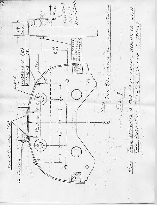
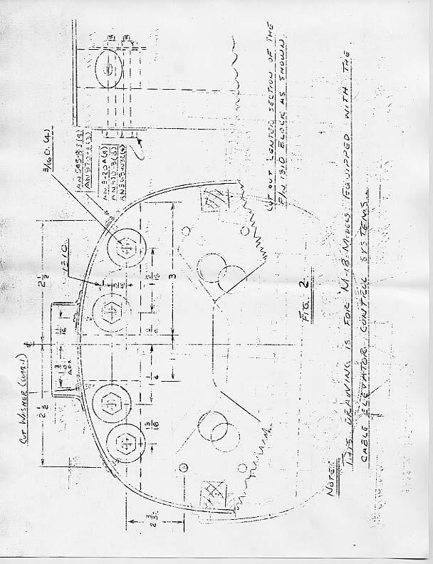
1 IMPORTANT - STATE AIRCRAFT REGISTRATION NUMBER IN ALL CORRESPONDENCE MOONEY AIRCRAFT, INC. M-l8 SERVICE LETTER NO.17 (This Service Letter is FAA. Approved) DATE: OCTOBER 24, 1959 SUBJECT: REAR BULKHEAD REINFORCEMENT MODELS AFFECTED: NOTED TIME OF COMPLIANCE: IN CONJUNCTION WITH MOONEY M-l8 SERVICE LETTER NO. 16 PARTS LIST: Kit #1, P/N 1310 Block (l) Kit #2, P/N 1307 Plate (Front ) (1) P/N 1308 Plate (Rear) (1) P/N /-8 Fittings (1 ea.) Kit #3, P/N 1307 Plate (Front) (1) P/N 1308 Plate (Rear) (1) P/N /-8 Clips (Upper) (1 ea.) P/N /-8 Clips (Lower) (1 ea.) INTRODUCTION Reports involving M-l8 aircraft, manufactured prior to 1953 have been received concerning the following defects in the rear-most bulkhead. 1) Loose glue joint between bulkhead and tail cone skin at top of bulkhead. 2) Separation of plywood web and spruce core. 3) Cracks of plywood web and/or spruce core in the area of the empennage attachment brackets. This rear bulkhead area should be carefully inspected (see M-18 Service Letter No. 16, Item A-8) with particular attention to the items listed above on all M-18 aircraft including those manufactured from 1953 on. These later aircraft had clips (P/N /-2) attached to the upper longerons (on top) which picked up the upper bolt through the empennage attachment bracket. The rework described below is divided into parts with the airplanes affected listed in Item 1 of each part. Parts for the required rework are available at no cost. PART A 1. All airplanes having the defect described in Item 1 of the Introduction are to be repaired in accordance with Figure 1 or Figure 2 depending on the type of elevator control system. 2. Order Rework Kit SL PART B 1. All airplanes not having P/N /-2 clips installed and all airplanes having the defects described in Items 2 or 3 of the Introduction are to be repaired as follows:
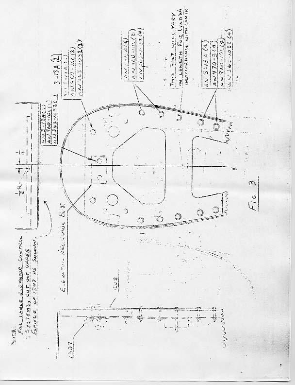
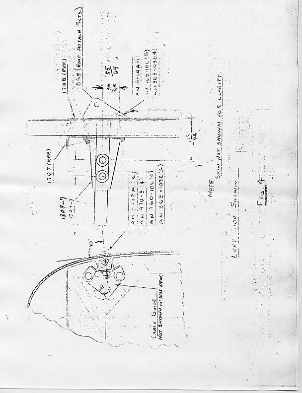
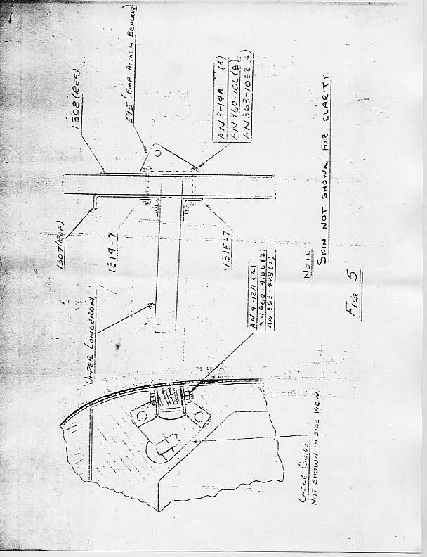
2 Page 2 M-18 Service Letter No. 17 PART C a. Remove the following items from bulkhead: i. Elevator bellcrank bracket ii. Lead ballast weight if installed iii. Longeron clips P/N /-2 (if installed) by removing bolt through upper longeron b. Clean excess paint or glue off faces of bulkhead so that plates bear on flat surface. c. Attach P/N 1307 and 1308 plates to bulkhead using AN3 bolts through the tail attachment holes, elevator bellcrank bracket and holes, and lead ballast and holes. NOTICE - Do not reassemble tail attachment brackets at this stage. d. Using P/N 1308 as template drill 3/16 diameter holes (10) through bulkhead and P/N Exercise care to drill holes perpendicular to bulkhead. Install AN3 bolts specified in Figure 3 for attachment of elevator bellcrank bracket, lead ballast, and through holes drilled. Exercise care in tightening bolts so as not to crush bulkhead. 1. For all airplanes not having P/N /-2 clips installed, the following must be accomplished after compliance with Part B: a. Mark the location on the outside of tail cone of the four holes through the upper longeron as shown on Figure 4. b. Drill one of the holes on each side with a 1/16 diameter drill perpendicular to skin. Examine the inner face of the longerons. The holes should be in the center of the longeron. If the hole is off-center, correct the error as much as the original hole will allow by re-drilling the other two holes with a 1/8 diameter drill. Applying the same correction, drill the other two holes with a 1/8 diameter drill. c. Install P/N /-8 fittings, empennage attachment brackets and cable guides as shown in Figure 4. d. Block fittings to prevent play and, using 1/8 diameter holes as guides, drill 11/64 diameter holes (4) through longerons and 1309 fittings. Using 11/64 diameter holes as guides, drill out holes to 3/16 diameter. e. Bolt the /-8 fittings to the longerons as shown in Figure 4. Exercise care in tightening bolts so as not to crush wood. PART D 1. For airplanes which had P/N /-2 clips installed and which have been reworked in accordance with Part B, the following shall be accomplished: a. Reinstall empennage attachment brackets and cable guides and replace P/N /-2 clips with P/N /-8 clips and add P/N /-8 clips on lower side of upper longeron picking up lower bolt of empennage attachment brackets as shown in Figure 5. Install vertical bolt through two clips and longeron as shown. 2. Order Kit No. SL
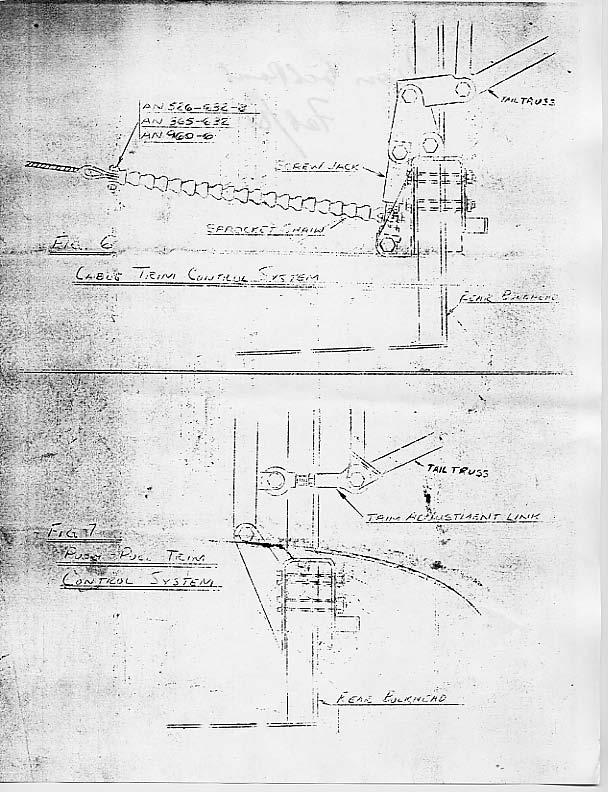
3 Page 3 M-l8 Service Letter No. 17 PART E 1. All airplanes having been reworked according to Part B shall have the following accomplished: a. Reinstall empennage and check for empennage play (see M-18 Service Letter No. 16, Item A-9). b. The elevator control system shall be adjusted as necessary to correct for the addition of.051 thick plates to bulkhead. In adjusting heim bearings (1 to 2 turns) exercise care that the end of the threaded shank is not pulled out past the inspection hole on the side of the female threaded rod end. (1) Remove forward access panel on the right hand side of the airplane for access to elevator control system linkage. (2) With stabilizer in approximately level position, set control stick in neutral position (perpendicular to horizontal reference). (3) For airplanes which feature a cable control elevator system forward of the rear bulkhead, the adjustment of the elevators is done by adjusting turnbuckles (take up on one and unscrew the other) until elevators are in a neutral position while maintaining control stick in approximately neutral position,. (4) For airplanes which feature a push-pull rod elevator control system forward of the rear bulkhead, the adjustment of the elevators is done by adjustment of the heim bearing at either the rear or the front of the push-pull rod in the tail cone until the elevators are level with the stabilizer with the control stick in the neutral position. c. The trim control system shall be adjusted as described below so as to have the correct angular travel after installation of P/N 1307 and 1308 plates. (1) Level airplane until front face of main wing spar is perpendicular to horizontal reference. Pull seat forward for access to spar. (2) Set trim control to "nose up" position. (3) For airplanes equipped with a cable control trim system, the adjustment is made as follows: i. Remove chain from screwjack by removing bolt connecting sprocket chain to cable on one side. See Figure 6. ii. Turn screwjack at sprocket until the leading edge of vertical fin is inclined forward 3.5 to vertical reference. iii. Reinstall chain around sprocket and connecting bolt to cable end. iv. Check "nose down" trim position for vertical fin leading edge inclination rearward of 1.5 to vertical reference. (4) For airplanes equipped with push-pull rod trim control system forward of the rear bulkhead, the adjustment is made as follows: i. inclined forward 3.5 with trim setting in "nose up" position. ii. Check inclination of leading edge of vertical fin for 1.5 rearward for trim in "nose down" position.
4
5
6
7
8
9
SERVICE BULLETIN. No. SB-AG-45 Rev. B JUNE 1, 2007 FIN SPAR & ATTACH FITTINGS INSPECTION AND UPGRADE IMPORTANT:
 THRUSH AIRCRAFT, INC. P.O. Box 3149 300 Old Pretoria Rd. Albany, GA 31706-3149 Product Support 229-883-1440 ext. 341 FAX 229-436-4856 jbays@thrushaircraft.com SERVICE BULLETIN No. SB-AG-45 Rev. B JUNE
STOL CH nd Edition Drawings July 20, 2010 Summary of changes from Edition 1 to Edition 2.
 STOL CH 750 2 nd Edition Drawings July 20, 2010 Summary of changes from Edition 1 to Edition 2. Page Date Drawing Title 75-G-0 07/10 Three View Drawing 75-G-1 07/10 Drawings Index 75-G-2 03/10 General
Chapter 20. Standard Practices - Airframe
 Chapter 20 Standard Practices - Airframe PAGE 1 Chapter 20 Table of Contents Chapter Title 20-00-00 GENERAL.................................. 3 20-10-00 STANDARD PRACTICES AIRFRAME........... 4 20-10-01
SERVICE BULLETIN SB-GL12-01R GREAT LAKES AIRCRAFT HORIZONTAL STABILIZER SPAR INSPECTION COMPLIANCE TIME: APPROVAL: PURPOSE: BACKGROUND:
 SUBJECT: AFFECTED MODELS: 2T-1A 0501 and 0502 2T-1A-1 0503 through 0699 2T-1A-2 0701 through 1012 COMPLIANCE TIME: APPROVAL: PURPOSE: BACKGROUND: Released: 01/25/2012 Page 1 of 5 HORIZONTAL STABILIZER
STOL CH st Edition 1 st Revision Drawings Summary of changes from Edition 1 to Edition 1 Revision 1.
 STOL CH 750 1 st Edition 1 st Revision Drawings Summary of changes from Edition 1 to Edition 1 Revision 1. Page Date Drawing Title 75-G-0 01/10 Three View Drawing 75-G-1 01/10 Drawings Index 75-RX-1 05/09
REAR FUSELAGE ASSEMBLY
 SECTION 2 Rear Fuselage Bottom Assembly Ref Dwg 8FR-2 SECTION 2 - Page 1 of 17 FUSELAGE BOTTOM SKIN 8F2-3A Note: The edges of skin 8F2-3A are not a straight line. Check: edge distance from the center of
FORWARD FUSELAGE SIDES & REAR TOP SKINS
 FORWARD FUSELAGE SIDES & REAR TOP SKINS WORK REPORT Step No. Check Parts / Tools Qty Preparations. 1 [ ] 6F5-3 Upper Front Longerons 2 2 [ ] 6F5-5 Heel Support 1 3 [ ] 6F5-2 Front Floor Skin 1 3 [ ] Firewall
Photo-Guide (ZE & ZE )
") Photo-Guide (ZE-2009-05 & ZE-2009-07) The following photo-guide is for educational purposes only. It is intended to assist owners and/or aircraft mechanics with the installation of elements from from 6Z-1G
Photo-Guide (ZE-2009-05 & ZE-2009-07) The following photo-guide is for educational purposes only. It is intended to assist owners and/or aircraft mechanics with the installation of elements from from 6Z-1G
Air Tractor, Inc. Repairs Page 5-i AT-802/802A July 30, 2008
 Repairs Page 5-i TABLE OF CONTENTS SECTION 5- REPAIRS No. Page FUSELAGE FRAME REPAIRS... 5-1 FORWARD CLAMP BLOCK BOLT FAILURE..5-1 STANDARD STRUCTURAL REPAIR DRAWINGS...5-1 Repairs Page 5-1 April 12, 2010
SERVICE BULLETIN
 SERVICE BULLETIN 14-02-03 Date Released: February 3, 2014 Date Effective: February 3, 2014 Subject: Affected Models: Required Action: Time of Compliance: Cracking in elevator spar web near elevator attach
Skymaster ARF F-18E Instructions Manual
 Skymaster ARF F-18E Instructions Manual first: Take out the front servos mount, install front fuel tank before installing nose cone connect nose cone to fuselage by 6 screw Take out the 6 screws and Bottom
12. Wings, Flaps, Ailerons and Struts
 12. Wings, Flaps, Ailerons and Struts Fit Aileron Hinges Reference: Drawing 20270K2 Photo 12.1 Parts Required: 2007092 Aileron LS 200809N Aileron RS 2001394 Hinge 3/16 A1 (4) 2001694 Hinge Pin (4) PH0059N
CENTER WING SECTION (CWS) WORK REPORT
 WORK REPORT") CENTER WING SECTION (CWS) WORK REPORT No. Check Parts / Description Qty PHASE 1: Preparations 1 [ ] 6V1-3 Rear ribs 2R & 2L 1 [ ] L Angle 6 2 [ ] 6V2-1 Rear Ribs.032 2R & 2L 2 [ ] 6V5-1 Gear Rib Doubler
CENTER WING SECTION (CWS) WORK REPORT No. Check Parts / Description Qty PHASE 1: Preparations 1 [ ] 6V1-3 Rear ribs 2R & 2L 1 [ ] L Angle 6 2 [ ] 6V2-1 Rear Ribs.032 2R & 2L 2 [ ] 6V5-1 Gear Rib Doubler
RESolution V2 Manual
 RESolution V2 Manual Note for the German Manual: Yellow Bottle thick CA Pink Bottle Med CA Blue tube 5 minute Epoxy Green tube 90 Minute Epoxy Construction of the Fuselage Step 1: Cover the plan with a
REAR FUSELAGE ASSEMBLY
 SECTION 5 Tail Attachments on Fuselage Ref Dwg 8RU-3 The rudder hinge line (HL) is parallel to the aft edge of the fuselage skin SECTION 5 - Page 1 of 9 Looking at the top of the rear fuselage. Stabilizer
STC GROUP LLC 480 RUDDIMAN DRIVE MUSKEGON, MICHIGAN REPORT NO: REV - TRIO AUTO PILOT INSTALLATION INSTRUCTIONS CESSNA MODEL 182
 STC GROUP LLC 480 RUDDIMAN DRIVE MUSKEGON, MICHIGAN 49445 REPORT NO: 1006003 REV - TRIO AUTO PILOT INSTALLATION INSTRUCTIONS CESSNA MODEL 182 DATE: Original Issue 10 July, 2017 WRITTEN BY: Paul Odum APPROVED
Replacement of Pitch Link Retainer and Service Improvement of the Pitch Control System. Effectivity: Helicopters manufactured prior to January, 1981
 Page 1 of 12 Date: December 2, 1981 Subject: Models: Replacement of Pitch Link Retainer and Service Improvement of the Pitch Control System F-28C and 280C Effectivity: Helicopters manufactured prior to
Bashing The Hanger 9 Cessna 182 ARF Part 4
 Bashing The Hanger 9 Cessna 182 ARF Part 4 Eric Helms Pongo Air This is the final installment of a four-part article covering a variety of modifications incorporated into a Hanger 9 Cessna 182 ARF. Upgrades
STANDARD CANOPY WORK REPORT B-1
 STANDARD CANOPY WORK REPORT B-1 No. Check Parts / Tools Qty _ Canopy Lock 1 [ ] 6E2-3 Canopy Hinge Block 1 2 [ ] 6E4-5 Canopy Side Frame 2 2 [ ] 6E2-1 Canopy Lock Assembly 1L + 1R 3 [ ] 6E2-4 Rear Lock
16. Wing Final Assembly and Installation
 Section Objective: Installation and rigging of ailerons. Pitot tube install, and any other wing related items. Required Parts: Left aileron push rod ALA-0072, Right aileron push rod ALA-0073, Push tube
JK FRONT FENDER FLARE INSTALLATION INSTRUCTIONS
 JK FRONT FENDER FLARE INSTALLATION INSTRUCTIONS TOOLS NEEDED 3/16 Allen Wrench 1/2 Socket or wrench 10mm Socket Flat head screwdriver HARDWARE 5/16 x 3/4 button heads (14) 5/16 x 1 button heads (8) 5/16
FLITZEBOGEN-2 Assembly instructions
 FLITZEBOGEN-2 Assembly instructions Trim the end of the fuselage to the length of 925mm from the nose. Be careful to avoid splitting the carbon fibers. Sand the base of the stab mount in preparation for
ENGINEERING REPORT DATE. This Service Letter is applicable to all models and all serial numbers of Air Tractor aircraft.
 WICHITA FS, TEXAS SUBJECT: Rudder Controls Inspection and Maintenance APPLICABILITY: 1 8 This Service Letter is applicable to all models and all serial numbers of Air Tractor aircraft. PURPOSE: The purpose
Corvus Racer CC
 Corvus Racer 540 35CC Item No:L-G035008 Specifications Wing Span Length Wing Area Flying Weight Glow Gasoline Electric Radio mm mm 1200sq in (77.4sqdm) 9.9-12lbs(4.5-5.5kg) 91-1.20(2C) 1.10-1.40(4C) 20-40cc
9.3 FUSELAGE ASSEMBLY 14/03/02
 9.3 MATING THE TAIL CONE TO THE CABIN 1) Trim the bottom flange of both FUS-339 side skins on the tailcone assembly as in Figure 1. 2) Remove the bottom two RBULK 2A s of bulkhead A on the tailcone. 3)
Edge 540 V3 35CC. Scheme A. Item No:L G Specifications. Flying Weight
 Edge 540 V3 35CC Item No:L G035016 Specifications Wing Span Length Wing Area Flying Weight Glow Gasoline Electric Radio Description 76 (1930mm) 74 (1879mm) 1200sq in(77.4sqdm) 9.9 12lbs(4.5 5.5kg) 91 1.20(2C)
PORTABLE ADJUSTABLE BASKETBALL SYSTEM
 Instruction Manual PORTABLE ADJUSTABLE BASKETBALL SYSTEM P A R T S L I S T 5 1/2 and 8 safe play clearance Item Qty Description Item Qty Description A 1 Portable Base Assembly M 4 1/2 Lock Nut B 2 Front
STOL CH H3-3SP Center Hinge Bracket. IMPORTANT: The Bracket 7H5-3SP is not symmetrical
 7H3-3SP Center Hinge Bracket IMPORTANT: The Bracket 7H5-3SP is not symmetrical Using a square helps layout and mark the perpendicular and the hinge hole. Note: Position of 1/4 hinge hole is 115.5mm from
CIRRUS AIRPLANE MAINTENANCE MANUAL
 FASTENER AND HARDWARE GENERAL REQUIREMENTS 1. DESCRIPTION This section contains general requirements for common hardware installation. Covered are selection and installation of cotter pins, installation
Aircraft assembly and disassembly
 Following instructions are related to ATEC 321(322) FAETA with wingtanks, but in general the basic methodics (besides several few differencies) is applicable also to other ATEC models. Aircraft assembly
SERVICE BULLETIN
 14401 Keil Road NE, Aurora, Oregon, USA 97002 PHONE 503-678-6545 FAX 503-678-6560 www.vansaircraft.com info@vansaircraft.com Service Letters and Bulletins: www.vansaircraft.com/public/service.htm SERVICE
Horizontal Stabilizer Service Bulletin
 Horizontal Stabilizer Service Bulletin Date: Friday November 19, 2004 To: All Super Rebel/Moose owners Re: Horizontal stabilizer tip rib INFO: A number of Super Rebels have shown cracking on the tip rib/rear
Cut the center and pre-drill the Hinge Plate. Do not drill the Rudder Hinge hole at this time.
 7F4-1 Upper Rudder Hinge Plate Layout the cut for the Upper Hinge Plate. Measure and mark the center for the Rudder Hinge. The center hinge hole is 75mm from the back edge of 7F4-1. Cut the center and
Builders Log Report S
 12/09/01 Reamed Horizontal Stabilizer Bushings I reamed seven bushing locations to.4375 where elevator attaches to horizontal stabilizer. The proximity of the locations to structural tubing made it difficult
STC GROUP LLC 480 RUDDIMAN DRIVE MUSKEGON, MICHIGAN REPORT NO: G REV E TRIO AUTO PILOT INSTALLATION INSTRUCTIONS
 STC GROUP LLC 480 RUDDIMAN DRIVE MUSKEGON, MICHIGAN 49445 REPORT NO: G-1006-51 REV E TRIO AUTO PILOT INSTALLATION INSTRUCTIONS CESSNA MODEL 182 WITH PREVIOUS CESSNA EQUIPPED AUTO PILOT DATE: Original Issue
Section 75-ZA-2. Rudder Mounting
 Section 75-ZA-2 This manual has been prepared for installation of the Rudder. This photo assembly manual is intended as a supplement to the drawings. If there is any discrepancy between this manual and
SERVICE BULLETIN. No. SB-CR-017 Rev.: - Date: Page: 1 of 7 Date: -
 Page: 1 of 7 Date: - MODEL AFFECTED: SUBJECT: AIRCRAFT AFFECTED: COMPLIANCE: PS-28 Cruiser / SportCruiser / PiperSport Replacement of rivets for bolts in the area of the main landing gear attachment. All
INSTALLATION MANUAL IOWA MOLD TOOLING CO., INC. BOX 189, GARNER, IA MANUAL PART NUMBER:
 PARTS-1 Model 24562/28562 Crane INSTALLATION MANUAL IOWA MOLD TOOLING CO., INC. BOX 189, GARNER, IA 50438-0189 641-923-3711 MANUAL PART NUMBER: 99903701 Iowa Mold Tooling Co., Inc. is an Oshkosh Truck
STC GROUP LLC Page Ruddiman Drive PA-28 & PA-32 Trio Pro Pilot Installation Instructions North Muskegon, Michigan 49445
 STC GROUP LLC Page 1 STC GROUP LLC 480 RUDDIMAN DRIVE MUSKEGON, MICHIGAN 49445 DOCUMENT NO: 1028001 REVISION D TRIO PRO PILOT INSTALLATION INSTRUCTIONS PIPER AIRCRAFT CORPORATION PA-28 AND PA-32 DATE:
ZODIAC 601 XL. ZODIAC CH 601 Series. Parts are labeled for easy identification with a part number and description:
 CH 601 Series Parts are labeled for easy identification with a part number and description: Part number example: 6T4-4 Vertical Tail Spar 6 - Zodiac CH 601 model T - Rudder section of the Aircraft drawings.
THE APOGEE A 100-INCH AMA DURATION SAILPLANE FROM DYNAFLITE
 THE APOGEE A 100-INCH AMA DURATION SAILPLANE FROM DYNAFLITE Apogee is the intermediate sailplane designed to be competitive in AMA duration contests. Effective spoilers, rudder and full flying stabilizer
Fokker D8 Master Instructions
 Fokker D8 Master Instructions Rev 1 Congratulations on your new project. The Fokker D8 is a marvellous subject that highlights the success of a monoplane design. The construction of the plane is similar
ZODIAC CH 601 Series Kit Aircraft
 ZODIAC CH 601 Series Kit Aircraft THE FOLLOWING IS A DRAFT MANUAL This manual has been written and published strictly for informational purpose. It has been prepared as a guide to facilitate the assembly
Anti-Chattering Retrofit Assembly
 Anti-Chattering Retrofit Assembly Please follow through these instructions carefully and thoroughly. If you have questions, feel free to contact a Bend-Tech service representative at our office 651-257-8715
CLUB-SPORT ROLL BAR: Volkswagen Mk4 Golf
 HPA Motorsports Inc. 604-888-7274 www.hpamotorsport.com CLUB-SPORT ROLL BAR: Volkswagen Mk4 Golf Congratulations on the purchase of your Club-Sport Roll Bar from HPA Motorsports! The engineering elements
Note - the nose ribs and are thinner than the main ribs. These nose ribs will use a thinner rib cap than the ribs. This is per design.
 Stabilizer rev 1.2 The SE5a stabilizer is the heartbeat of the tail and is recreated like the full scale version. All tail pieces depend on the stabilizer. It uses the steel fittings, pulleys, inspection
Metal Aircraft Landing Light Installation Instructions
 Metal Aircraft Landing Light Installation Instructions This landing light kit was designed for the Thorp T-18 as a method of installing a halogen landing light in the leading edge of the outer bay of the
SZD-10 bis CZAPLA ASSEMBLY MANUAL IN PICTURES
 1 RUDDER Plan and parts: 2 Assembly steps: Photo above: glue together rudder spar, ribs and trailing edge. Clamp spar to a flat surface (chipboard on the photo) and make sure the straight aligment of the
1/16" Square balsa strip stock is used for the fuselage and tail surfaces structure. 10T 11T 11B (2) 10B. Pec Bea. Wingspan - 18"
 10B. Pec Bea. Wingspan - 18") 1/16" Square balsa strip stock is used for the fuselage and tail surfaces structure. 10T 9T 8 11T 12 7T 6T F-1 7 11 (2) 10 9 6 13 Pec ea CAD Drawing by Paul radley Sheet 1 of 8 Nose plug is a lamination
1/16" Square balsa strip stock is used for the fuselage and tail surfaces structure. 10T 9T 8 11T 12 7T 6T F-1 7 11 (2) 10 9 6 13 Pec ea CAD Drawing by Paul radley Sheet 1 of 8 Nose plug is a lamination
American Champion Aircraft Corp. Rochester, WI Page 1 of 5
 Service Letter: 444 Initial Revision Date: August 18, 2017 Title: American Champion Aircraft Corp. Rochester, WI 53167 Page 1 of 5 Installation of Aileron Hinge Reinforcement Models: 8KCAB serial numbers
Super Sky Surfer 2000 Assembly Instructions
 Super Sky Surfer 2000 Assembly Instructions Note: Plug and Play version of the Sky Surfer comes with fuselage pre-glued and motor/servos installed. If you wish to route antennas or wires through the tail,
STOL CH 701. Clamp a reference extrusion on the bottom of the spar. Clamp the bottom flange of the rib to the extrusion. Rear Root Rib 7V4-2
 Rear Root Rib 7V4-2 Clamp a reference extrusion on the bottom of the spar. Clamp the bottom flange of the rib to the extrusion. Cleco the root nose rib to the spar Position the rear root rib at station
Instruction Manual. Specification:
 Instruction Manual H I G Specification: Wingspan: 133 cm (52.3 inches) Length : 104 cm (40.9 inches) Weight : 1830gr Engine : 25-32 two stroke Radio : 4 channel - 4 servo H W I N G KIT CONTENTS: We have
Land Rover Defender 110 Station Wagon (L172) Fitting Instructions
 Fitting Instructions") Land Rover Defender 110 Station Wagon (L172) Fitting Instructions 1 Enterprise Court Unwrap the roll cage and unpack the individual fitting kits. At this point it is recommended that all components are
Land Rover Defender 110 Station Wagon (L172) Fitting Instructions 1 Enterprise Court Unwrap the roll cage and unpack the individual fitting kits. At this point it is recommended that all components are
Zodiac CH 601 XL drawing revision log, updates included in 4 th Edition, January 1, 2008.
 Zodiac CH 601 XL drawing revision log, updates included in 4 th Edition, January 1, 2008. 6-X-0 6-X-1 6-T-0 6-T-1 6-T-2 6-T-3 6-T-4 6-T-5 6-T-6 6-W-0 6-W-00 6-W-1 6-W-2 6-W-3 6-W-4 6-W-5 6-W-6 01/08 DRAWING
C-180 Builder s Manual
 C-180 Builder s Manual. May 20, 2002 Last revised July 11, 2002 Copyright! 2002 Douglas Binder, Mountain Models www.mountainmodels.com sales@mountainmodels.com (719) 630-3186 1 Required Equipment! Xacto
FUSELAGE CONSTRUCTION
 FUSELAGE CONSTRUCTION Note: prior to building and gluing on the work surface use protective covering on your building surface. (wax paper or clear wrap) Fit the laser cut Fuselage Front and Fuselage Rear
105" TIGER MOTH ARF INSTRUCTION MANUAL VERSION 1.0
 105" TIGER MOTH ARF INSTRUCTION MANUAL VERSION 1.0 Step 1. Installation of the aileron servos 1) Mount aileron servo to servo mounting blocks with servo s screws. Install servo mounting plate with screws.
INSTALLATION INSTRUCTIONS 3 BULL BAR 99-04, 04 "HERITAGE" F-150/250LD 2WD, 97-04, 04 "HERITAGE" 4WD WD EXPEDITION/ WD EXPEDITION PART
 INSTALLATION INSTRUCTIONS 3 BULL BAR PART #B-F1971;B-F2971 PARTS LIST: 1 Bull Bar 2 12-1.75mm x 130mm x 40mm Hex Bolts 1 Driver/Left Mounting Bracket 4 12-1.75mm x 35mm Hex Bolts 1 Passenger/Right Mounting
Desk/Wall-Mount Rack
 Desk/Wall-Mount Rack Patent(s) Pending Installation Instructions Post P/N: 119-1752 119-1781 119-1782 119-4014 Frame P/N: 119-1591 119-1754 119-1755 Kit Contents (2) Frames (4) Posts Assembly Hardware
Chap. 9.2 SR3500 Fuselage Assembly - Cabin. MODEL: SR Murphy Aircraft Mfg. Ltd. All rights reserved.
 26/06/2006 Page 1 26/06/2006 Page 2 26/06/2006 Page 3 Parts List for Gear Box No. Part Number Description Qty Required 1,23 FUS0711QL BRACING CHANNEL 2 2,22 FUS0711QR BRACING CHANNEL 2 3 FUS301QB CARRYTHROUGH
1/6 PA-25 PAWNEE. *Specifications are subject to change without notice.*
 1/6 PA-25 PAWNEE INSTRUCTION MANUAL [ A335 Kit ] Wing Span : 72 in / 1830 mm Wing Area : 736 sq in / 47.5 sq dm Flying Weight : 6.6 lbs / 3000 g Fuselage Length : 48 in / 1220 mm Requires : "Glow Power"
ZODIAC CH650. ZODIAC CH 650 Series. Parts are labeled for easy identification with a part number and description:
 CH 650 Series Parts are labeled for easy identification with a part number and description: Part number example: 6T4-4 Vertical Tail Spar 6 - Zodiac CH 650 model T - Rudder section of the Aircraft drawings.
MXS R 30CC. Item No:L G Specifications. 67 1/2"(1720mm) (2C) (4C) 26 35cc gas DLE 30/35RA MLD35 JC30Evo.
 (2C) (4C) 26 35cc gas DLE 30/35RA MLD35 JC30Evo.") MXS R 30CC Item No:L G030008 Specifications Wing Span Length Wing Area Flying Weight Glow Gasoline Electric Radio Description Covering Material Carbon Fibre : 75"(1915mm) 67 1/2"(1720mm) 1023sq in(66sq
MXS R 30CC Item No:L G030008 Specifications Wing Span Length Wing Area Flying Weight Glow Gasoline Electric Radio Description Covering Material Carbon Fibre : 75"(1915mm) 67 1/2"(1720mm) 1023sq in(66sq
Thank you for your purchase of the Lee Ulinger, FoamtanaS, Yak-55, or Extra 330 3D Depron foam, Aerobatic airplane.
 Thank you for your purchase of the Lee Ulinger, FoamtanaS, Yak-55, or Extra 330 3D Depron foam, Aerobatic airplane. Tools you will need to build Recommended additional items: #11 hobby knife Motor: Hacker
Introduction. Rocky Mountain Westy Swing Away Carrier Kit Installation Instructions
 Rocky Mountain Westy Swing Away Carrier Kit Installation Instructions Introduction Thank you for purchasing the Rocky Mountain Westy Swing Away Carrier Kit. We pride ourselves in the products we develop
RACER TECH rzr lift kit installation instructions
 RACER TECH rzr 170 2 lift kit installation instructions Thank You for purchasing this kit. You should have received the following: (2) - Front spindle relocators (2) Front relocator shims (1) - Rear upper
Citabria Pro. Aerobatic Parkflyer. by Joel Dirnberger
 Citabria Pro Aerobatic Parkflyer by Joel Dirnberger Revision C: December 21, 2004 Citabria Pro Building Instructions Length: Wingspan: Wing Area: Flying Weight: Wing Loading: Functions: Specifications:
MECOA EZ-4061 Trainer
 MECOA EZ-4061 Trainer EZ-4061 is a newly designed, Almost Ready to Fly kit. It is an extremely easy to control trainer with strong construction and excellent aerodynamic performance. This is a great choice
frame bracket Dodge x 2 & 4 x 4 (6-1/2 & 8 Boxes Includes Mega Cab)
") , Rev 4 02/19 frame bracket 8552026 Dodge 3500 4 x 2 & 4 x 4 (6-1/2 & 8 Boxes Includes Mega Cab) 14 5 7 2 4 11 9 10 17 3 6 1 8 13 15 16 18 12 ITEM PART # DESCRIPTION QTY. 1 00085.50 FLAT WASHER 10 2 00248
, Rev 4 02/19 frame bracket 8552026 Dodge 3500 4 x 2 & 4 x 4 (6-1/2 & 8 Boxes Includes Mega Cab) 14 5 7 2 4 11 9 10 17 3 6 1 8 13 15 16 18 12 ITEM PART # DESCRIPTION QTY. 1 00085.50 FLAT WASHER 10 2 00248
FORD 4100/4400 SUPERRAIL MOUNTING KIT WITH ADAPTER FOR B&W GOOSENECK PART #4431
 FORD 4100/4400 SUPERRAIL MOUNTING KIT WITH ADAPTER FOR B&W GOOSENECK PART #4431 Installation Instructions SPECIFICATIONS Fits 1999 2016 Ford F250 & F350 Short Bed Mounts to B&W gooseneck part #1108 & 1111
Hobby Lobby Zip Supplementary instructions Please refer to the included drawings while using these assembly instructions
 Materials needed: 15 or 30 minute epoxy Medium CA Masking tape Scotch tape Servo Tape Wax paper Tools Needed: Pencil or marker Flat building surface Hobby knife or razor blade 7/64" or 3mm drill bit 3/16"
STC GROUP LLC 480 RUDDIMAN DRIVE NORTH MUSKEGON, MICHIGAN REPORT NO: REVISION H
 STC GROUP LLC 480 RUDDIMAN DRIVE NORTH MUSKEGON, MICHIGAN 49445-2783 REPORT NO: 1006004 REVISION H TRIO AUTO PILOT PROVISIONS INSTALLATION INSTRUCTIONS 1953 CESSNA 180 THROUGH 1962 180E 1956 CESSNA 182
The Olympic DLG. (Discus launch glider) by Chris Brislin
 by Chris Brislin") The Olympic DLG (Discus launch glider) by Chris Brislin 1 Contents Parts List/ What you need 3 Before you begin 4 Wing Construction 5-9 Pod Construction 9-13 Tail assembly 13-? Control linkages 9-10 Finishing
The Olympic DLG (Discus launch glider) by Chris Brislin 1 Contents Parts List/ What you need 3 Before you begin 4 Wing Construction 5-9 Pod Construction 9-13 Tail assembly 13-? Control linkages 9-10 Finishing
LUNAR EXPRESS. Little
 Little LUNAR EXPRESS The Little Lunar Express kit contains all the parts necessary* to build a flying high power rocket: 1) Pre-slotted boattail 1) Airframe 5.5" long 1) Nose cone 2) Main fins 2) Stabilizer
V Installation instructions, accessories. Auxiliary seat. Volvo Car Corporation Gothenburg, Sweden V70 (00-08) 2002
 2002") Installation instructions, accessories Instruction No 8624018 Version 1.3 Part. No. 30749269, 30749270, 30749271, 30749272, 30749273, 30749274 Auxiliary seat M8901699 Volvo Car Corporation Auxiliary seat-
Installation instructions, accessories Instruction No 8624018 Version 1.3 Part. No. 30749269, 30749270, 30749271, 30749272, 30749273, 30749274 Auxiliary seat M8901699 Volvo Car Corporation Auxiliary seat-
4Post and 2Post Sliding Rails for Lenovo/IBM M5
 Patent(s) Pending 4Post and 2Post Sliding Rails for Lenovo/IBM M5 4Post Page 2 2Post Center Page 4 Installation Instructions Kit P/N: 122-4818 Kit Contents Kit Contents: (2) (Left & Right) (2) Inner Rail
Stream NXT - assembly instructions
 Stream NXT - assembly instructions Recommended settings CG (measured from root leading edge): Speed/launch camber (+down, near the wing root): Cruise camber (+down, near the wing root): Thermal camber
BOBS CARD MODELS. De Haviland Dash-8 water-bomber (1:72)
") BOBS CARD MODELS www.bobscardmodels.com De Haviland Dash-8 water-bomber (1:72) A Canada de Haviland Dash-8 fitted with a large water tank, complements the French aerial firefighters' fleet of Canadairs
BOBS CARD MODELS www.bobscardmodels.com De Haviland Dash-8 water-bomber (1:72) A Canada de Haviland Dash-8 fitted with a large water tank, complements the French aerial firefighters' fleet of Canadairs
EXTRA 330SC 60CC. Item No:H G Specifications cc gas DA50,DA60, DLE55, DLE60(twin), 3W55. Description
, 3W55. Description") EXTRA 330SC 60CC Item No:H G060011 Specifications Wing Span Length Wing Area Flying Weight Gasoline Radio Description Carbon Fibre : 92" (2347mm) 84 1/2 " (2060mm) 1526.8 sq in(98.5sq dm) 16 17lbs(7300
EXTRA 330SC 60CC Item No:H G060011 Specifications Wing Span Length Wing Area Flying Weight Gasoline Radio Description Carbon Fibre : 92" (2347mm) 84 1/2 " (2060mm) 1526.8 sq in(98.5sq dm) 16 17lbs(7300
Adjustable Performance Trim Tab Kit PART# - RS27110-APT
 Adjustable Performance Trim Tab Kit PART# - RS27110-APT APPLICATION(S): Sea Doo RXP-X 260 We strongly recommend the use of a service manual to familiarize yourself with the various components and procedures
Bandit MK I & II & e-bandit I-PASR0049
 Bandit MK I & II & e-bandit I-PASR0049 Part I (for new model installation) INSTALLATION: Main Gear Mount Reinforcement Kits PA-SR-0049 Notice: The extended use of the Bandit ARF s (both Turbine and Electric
4Post and 2Post Universal Shelf System for 19 Racks
 Patent(s) Pending 4Post and 2Post Universal Shelf System for 19 Racks Installation Instructions Kit P/N: 108-4013 108-4261 Kit Contents (1) Shelf (2) Rear Brackets Front Hardware Kit (4) 8-32 x.375 Flat
Pow-R-Feed Systems Service Manual
 Pow-R-Feed Systems Service Manual Important Safety Instructions Please read this manual carefully and follow its instructions. Improper use or failure to follow these instructions could result in serious
Ryan STA Sport Scale Model Aircraft Assembly and Instruction Manual
 Ryan STA Sport Scale Model Aircraft Assembly and Instruction Manual Warning: This radio controlled model is not a toy. It requires skill to fly and is not recommended for the novice pilot. It should not
Nomad CONTROL SYSTEM IMPROVED PULLEY MOUNTING AT STATION (MOD N137) Page No Rev No
 Page No Rev No") CONTROL SYSTEM IMPROVED PULLEY MOUNTING AT STATION 67.95 (MOD N137) 1. PLANNING INFORMATION A. Effectivity (1) Aircraft Affected All Nomad N22 Series and N24 Series aircraft whose log books do not already
CONTROL SYSTEM IMPROVED PULLEY MOUNTING AT STATION 67.95 (MOD N137) 1. PLANNING INFORMATION A. Effectivity (1) Aircraft Affected All Nomad N22 Series and N24 Series aircraft whose log books do not already
Continue gluing the remaining top parts ensuring the angled piece is glued well. Set aside and let dry. See photo below
 Radiator rev 1.1 The SE5a s radiator is one of the most recognized radiators in WW1. It is one of the components that defines the SE5a. The original SE5a has seen multiple radiator designs used during
METRICFATS.COM Thank you for purchasing your new Stealth Rear Turn Signals for your Yamaha Raider.
 METRICFATS.COM Thank you for purchasing your new Stealth Rear Turn Signals for your Yamaha Raider. The instructional sheets that follow are thoroughly detailed and should be studied BEFORE picking up a
HIGH-END TECHNOLOGY. Electric ducted fan Starfighter
 HIGH-END TECHNOLOGY RC Electric ducted fan Starfighter First we want to thank and congratulate you with your decision in buying one of our Kits. The Starfighter puts together very easily so there is not
Corvus Racer Colour schemes. AeroPlus RC Copyright 2013 All Rights Reserved
 Corvus Racer 540 59 Item No:A E050003 Specifications WING SPAN: 59"(1500mm) LENGTH: 54.1"(1374mm) WING AREA: 654sq.in.(42.2sq.dm.) FLYING WEIGHT: 4.6 5.3lbs(2000 2300g) Electric:Brushless outrunner 8Oz.
Zeon PDF Driver Trial
 Mach Dart Slope Soarer Congratulations on your purchase of the Mach Dart Glider. This aircraft was crafted utilizing the latest technology in composite model aircraft design and manufacture. The Dart is
How to Use the Jahn Forming System
 How to Use the Jahn Forming System 1. Preparation Gang drilling the plywood is the only preparation required. Holes need to be drilled 1/8" larger than the snap tie head. Normally, a 5/8" diameter drill
2000 Tomlynn Street P.O. Box 6861 Richmond, Virginia / FAX 804/ Service Bulletin
 Sequoia Aircraft Corporation 2000 Tomlynn Street P.O. Box 6861 Richmond, Virginia 23230 804/353-1713 FAX 804/359-2618 Service Bulletin Service Bulletin No. 93-1 Subject: Flap Flutter Date: June 24, 1993
TIGER MOTH 120 ASSEMBLY INSTRUCTIONS
 TIGER MOTH 120 ASSEMBLY INSTRUCTIONS SPECIFICATIONS Wing Span: Length: Radio: Flying Weight: 1920mm 1580mm 4 channel with 6 servos 4200g AILERON ASSEMBLY 1 Start by removing the servo cover from the bottom
SPUNKY ASSEMBLY MANUAL
 SPUNKY ASSEMBLY MANUAL Please read the tips section at the back of this manual regarding the use of laser cut parts. The proper removal and preparation of these parts is important. When laser cut, some
E-AERO EPP PITTS KIT From BP HOBBIES. Parts Included in kit
 E-AERO EPP PITTS KIT From BP HOBBIES Parts Included in kit Thank you for purchasing the BP Hobbies/E-aero EPP Pitts. Please take the time to read through the instruction manual before beginning the build.
Piper Cherokee /3 scale. Construction Manual
 Piper Cherokee 140 1/3 scale Construction Manual STAB CONSTRUCTION 1. Remove foam cores from cradle and place on flat surface. Inspect pieces before you epoxy halves together making sure leading and trailing
Extra 330LT CC. 2 Colour schemes H-G120001A ORACOVER FERRARI RED # ORACOVER WITH # ORACOVER BLACK # ORACOVER SILVER #
 Extra 330LT 85-125CC Item No:A-G120001 Specs: WING SPAN: LENGTH: WING AREA: FLYING WEIGHT: ENGINE: RADIO: Description Covering Material Carbon Fibre: 111 (2833mm) 100" (2530mm) 2139sq in (138sq dm) 25.3-28lbs
C70 Window Roller Repair Taken from: Heres the problem:
 C70 Window Roller Repair Taken from: http://www.volvospeed.com/vs_forum/topic/115086-how-to-c70-window-rollers-permanent-fix/ Heres the problem: This happened to two separate window assemblys on my c70
Central New York Rocket Team Challenge 2018 Rocket Assembly Instructions
 Central New York Rocket Team Challenge 2018 Rocket Assembly Instructions Note: These instructions vary from those provided by the manufacturer of the rocket kits. There is also considerable varying discussion