How to Identify a PBM VALVE SERIES
|
|
|
- Brook Pope
- 6 years ago
- Views:
Transcription

1 How to Identify a PBM VALVE SERIES Series 0 (SP, DP, MP) 1. If it is a manual valve, the handle generally would be made of a cast iron or cast bronze. 2. If it is a manual valve, the stem at the very top is round and threaded followed by a square area right underneath. If automated, sometimes, not all the time, the round threaded area may be cut off. 3. There is a threaded packing gland (round with 2 or 4 flats) that threads down into the body holding the stem in (Part C below). 4. When repairing the valve the stem is inserted into the top of the body (Part D below). 5. There are no Belleville spring washers (not split washers) on the stem assembly. 1

 on the bottom of the stem and a large female square cut on the top of the ball.")
2 Revisions within Series 0 1. BE Series This was the first for PBM as a blow-out proof stem design. (All sizes ½ through 6, SP, FT, MP, DP). To identify this revision on the exterior of the valve look at the large gland nut that threads down into the body holding the stem in. If it is a HEX pattern it will be a BE design on ½ through 4. To identify this valve internally, look at the ball and stem engagement. The BE revision has a large square (larger than the diameter of the top of the stem) on the bottom of the stem and a large female square cut on the top of the ball. This is the only way to determine a 6 valve. (See below) If parts are required for this series, the following are non-standard parts: Part Gland Stem Support Ball Stem Part Number SPK-(SIZE LETTER)006B- SPRT(SIZE LETTER)035 SPHL(SIZE LETTER)002B- SPHL(SIZE LETTER)005B- BE 2
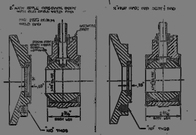
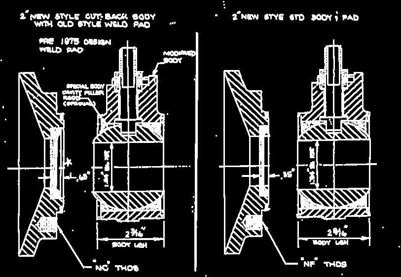
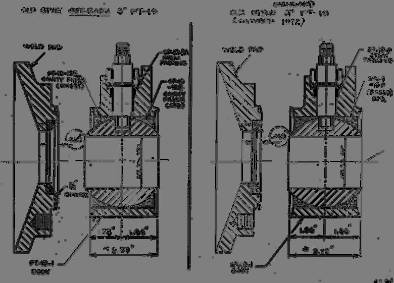
3 2. 3 &4 SP/FT/DP & 3 MP Stem Packing There some valves out there with a shorter stem packing in the above sizes and series. (See below) SPRTK009A- Longer packing SPRTK009 Shorter packing Note: SPRTK009 can be made from an SPRTK009A- by cutting off the sleeve. 3. Flush tank pads There are some Flush Tank valves out there (prior to 1979) with special cut-back pads and cut-back bodies. They are found in 2, 3 & 4 size valves. To identify one of these valves, look at the body with stem horizontal, using the stem as a centerline through the body cutting it in half, and note whether the body is symmetrical. If it is not, the valve is a cut-back style. You can also measure the width of the body on the 2 & 3 valves. Cut-down measurement Standard body
4 The 4 can only be identified by the pad itself, which has an angled chamfer area on the edge of the seat cavity. Parts that are affected by the cut-down bodies are: 2 & 3 replacement bodies and center sections. The body must be cut-back to fit up to the pad. 2, 3 & 4 cavity filler kits require one side of the cavity filler to be cut-back. 4

5 5
6 4. Fire Safe There are some older series valves out there that were titled fire-safe design (not tested to any fire-safe standard) with a metal encapsulating ring on the I.D. of tank pads and end fittings. The only way to determine this series is by looking at the fittings themselves. Series 1 (SP, SI, CS, DP, DP, MP, MI) 1. The stem is a double D shape (round in nature with 2 flats 180 degrees from each other) and is threaded all the way to the top. 2. When repairing, the stem enters the body from inside the body cavity. 3. The stem nut is a lock nut with a nylon insert in it. 4. There are Belleville spring washers (not split washers) on the stem assembly. 5. The handle is a stainless steel bent flat stock with a blue vinyl grip. Revisions within Series 1 1. There are some Series 1 valves out there that were titled fire-safe design (not tested to any fire-safe standard) with a metal encapsulating ring on the I.D. of tank pads and end fittings. The only way to determine this series is by looking at the fittings themselves. (See Item 4, Fire Safe, above.) Series 2 (API-607 Edition 3) 1. There is a large hex gland nut that threads down into the body holding the stem in. 2. The stem is a double D shape (round in nature with 2 flats 180 degrees from each other) and is threaded all the way to the top. 3. When repairing, the stem enters the body from inside the body cavity. 4. The ball will have a small hole in it in the upstream closed position. 5. The stem nut is a lock nut with a nylon insert in it. 6. There are Belleville spring washers (not split washers) on the stem assembly. 7. The handle is a stainless steel bent flat stock with a blue vinyl grip. 8. The body will have a flow indication stamped on it. 9. There will be graphite in stem area and body gasket area. 6
7 Series 3 (API-607 Edition 4) 1. PBM AN (ANSI series) & AF (Angle Stem Flush Tank) only. 2. Can be identified by looking at the stem area, if there is a (approx. ¼ ) flat bar plate covering the drilled body mounting pad that is bolted down then it is series The plate can be seen easily on a manual valve, on an actuated valve one would have to look directly below the actuator bracket. 4. There will be graphite in stem area and body gasket area Series 4 (SI and CS Series True-Bore ) 1. The stem is a double D shape (round in nature with 2 flats 180 degrees from each other) and is threaded all the way to the top. 2. When repairing, the stem enters the body from inside the body cavity. 3. The stem nut is a lock nut with a nylon insert in it. 4. There are Belleville spring washers (not split washers) on the stem assembly. 5. The CS series 4 valves have Belleville washers on the body bolts. 6. Handle is a stainless steel bent flat stock with a blue vinyl grip. 7. The end connections will generally only be Tri-clamp and butt-weld tube end connections. 8. MI Series 4 valves: a. Identified by square box configuration and a bolted bonnet on the top of the valve body b. End connections are usually Tri-Clamp or Extended Butt Weld (Tube) 9. MP Series 4 valves: c. Identified by square box configuration and a bolted bonnet on the top of the valve body d. End connections are usually Female NPT, Butt Weld (Pipe), Socket Weld, or Flange 10. The bore diameter through the seats and the ball will be equal to tubing I.D. (See Below) ½ = 0.37 BORE ¾ = 0.62 BORE 1 = 0.87 BORE 1½ = 1.37 BORE 2 = 1.87 BORE 2½ = 2.37 BORE 3 = 2.87 BORE 4 = 3.83 BORE 6 = 5.78 BORE 7
8 Series 5 (S,F,D) First introduced in the last quarter of 1999, this valve incorporates a Swing out/lift out design for easy removal and installation 1. There is a single hinge or hinges on the body to allow swing out. 2. The seat and body gasket may have a one-piece design or a two-piece design, as follows: Series 5 Valve Type Seat & Gasket Assemblies Industrial Standard CIP/SIP Steam Steam w/ CIP/SIP Sanitary Standard CIP/SIP Steam Steam w/ CIP/SIP 1- Piece 2- Piece SP, FT, DP 4 SS, FS 4 SI, FI, DI 4 SG, FG 4 SH, FH 4 SA, FA 4 SD, FD, DD 4 SE, FE 4 CS, FC, DC 4 SK, FK 4 SL, FL 4 SJ, FJ 4 3. Stems: e. ½ & ¾ is a double D shape (round in nature with 2 flats 180 degrees from each other) and is threaded all the way to the top. f. 1 is a double D shape (round in nature with 2 flats 180 degrees from each other) and has approximately a 3/8 area of unthreaded area at the top. g. 1½ through 6 is a double D shape (round in nature with 2 flats 180 degrees from each other) and has approximately a ½ to ¾ area of unthreaded area at the top that is square. 4. When repairing, the stem enters the body from inside the body cavity. 5. There are Belleville spring washers (not split washers) on the stem assembly. 6. The handle is a stainless steel bent flat stock with a blue vinyl grip. 7. The manual valve has two (2) stem nuts, one (1) below the handle and one (1) above. 8
9 Series 5 (SI,FI,DI,CS) First introduced in the last quarter of 1999, this valve incorporates a Swing out/lift out design for easy removal and installation. 1. There is a single hinge or hinges on the body to allow swing out. 2. The seat and body gasket may have a one-piece design or a two-piece design. (See table on page 8.) 3. Stems: a. ¼ through ¾ is a double D shape (round in nature with 2 flats 180 degrees from each other) and is threaded all the way to the top. b. 1 is a double D shape (round in nature with 2 flats 180 degrees from each other) and has approximately a 3/8 area of unthreaded area at the top. c. 1½ through 6 is a double D shape (round in nature with 2 flats 180 degrees from each other) and has approximately a ½ to ¾ area of unthreaded area at the top that is square. 4. When repairing, the stem enters the body from inside the body cavity. 5. There are Belleville spring washers (not split washers) on the stem assembly. 6. The handle is a stainless steel bent flat stock with a blue vinyl grip. 7. The end connections will generally only be Tri-clamp and butt-well tube end connections. 8. The manual valve has two (2) stem nuts, one (1) below the handle and one (1) above. 9. The bore diameter through the seats and the ball will be equal to tubing I.D. (See Below) ½ = 0.37 BORE ¾ = 0.62 BORE 1 = 0.87 BORE 1½ = 1.37 BORE 2 = 1.87 BORE 2½ = 2.37 BORE 3 = 2.87 BORE 4 = 3.83 BORE 6 = 5.78 BORE 9
10 Series 6 (API-607 Edition 4) 1. Can be identified by looking at the stem area, if there is a (approx. ¼ ) flat bar gland plate between the body drilling for the actuator mounting pad then it is series 6. The plate can be seen easily on a manual valve, on an actuated valve one would have to look directly between the actuator bracket. 2. The body bolts will be encapsulated by metal tubes. 3. Stems: a. ½ & ¾ is a double D shape (round in nature with 2 flats 180 degrees from each other) and is threaded all the way to the top. b. 1 is a double D shape (round in nature with 2 flats 180 degrees from each other) and has approximately a 3/8 area of unthreaded area at the top. c. 1½ through 6 is a double D shape (round in nature with 2 flats 180 degrees from each other) and has approximately a ½ to 1 area of unthreaded area at the top that is square. 4. The manual valve has two (2) stem nuts, one (1) below the handle and one (1) above. Series 8 forged and Series 9 cast 1. Series 8 forged product can be identified by the letters HF stamped into the body, end fitting, and on the stainless tag attached to the valve. A typical body number for a 1-inch valve would be SIHFE801. A 1-inch end would have a part number SIHFE803X- for a clamp end and SIHFE803F- for an extended butt weld tube end fitting. The part number on the stainless tag for a 1-inch would be SIHFE8X-G for a manual valve with clamp ends. The forged product has a unique appearance in contrast to cast product. 2. Series 9 cast product is identical to the Series 8 forged with exception of a cast body and end fittings. The Series 9 product can be identified by the number 9 cast into the body and end connections - sometimes Series 9 appears in full. 3. Series 8 and 9 are only sanitary true-bore products, so end connections are limited to clamp, extended butt weld for tube, and compression for tube ends. 10
We Are the Worldwide Provider for All Your Valve and Fitting Needs
 Product Catalog We Are the Worldwide Provider for All Your and Fitting Needs C&C strives to earn your business by offering an extensive line of high quality products with a proven track record for successful
PLASTIC BALLCOCK Includes: Vinyl Refill Tube, Float Rod, Flange Nut, Washer, 5/8 or 1/2 Coupling Nut and Water Level Adjustable Screw.
 Flush Valves PLASTIC BALLCOCK Includes: Vinyl Refill Tube, Float Rod, Flange Nut, Washer, 5/8 or 1/2 Coupling Nut and Water Level Adjustable Screw. Toilet Flappers 51005 10 Anti siphon 5 50 6.25 P51005
ANSI ORIFICE FLANGES METAL-KOREA
 METAL-KOREA ANSI ORIFICE FLANGES ORIFICE FLANGES are widely used in conjunction with orifice meters for measuring the rate of flow of liquids and gases. They are basically the same as standard welding
Installation, Maintenance and Operating Instructions
 Emission-Pak ASSEMBLY CARTRIDGES A, B AND C MODEL B FOR: 1/2 2 (DN 15 50) SERIES 5150 1/2 2 (DN 15 50) SERIES 5300 AND 530S 3/4 1-1/2 (DN 20 40) SERIES 6150 3/4 1-1/2 (DN 20 40) SERIES 6300 2 (DN 50) SERIES
UL / FM E-1 FIRE PROTECTION PRODUCTS INDICATOR POST FEATURES. *Applies to "ORDER LENGTH" codes B through F; code A has 22" adjustment.
 UL / FM MUELLER Indicator Post are used in fire protection systems and perform several functions. The Indicator Post provides a means to operate a buried or otherwise inaccessible valve. Also, the Indicator
This specification describes the minimum requirements for piping systems for the following service:
 SPEC-3004 1/7 1.0 APPLICATION This specification describes the minimum requirements for piping systems for the following service: Service Water Design Conditions Operating Conditions 10 PSIG @ 33 o F to
This specification describes the minimum requirements for service water piping systems (ie: cooling water, process water, etc.), located on surface.
, located on surface.") SPEC-3500 1/9 1.0 PURPOSE This specification describes the minimum requirements for service water piping systems (ie: cooling water, process water, etc.), located on surface. Note: This specification does
SPEC-3500 1/9 1.0 PURPOSE This specification describes the minimum requirements for service water piping systems (ie: cooling water, process water, etc.), located on surface. Note: This specification does
5.1 MUELLER CORPORATION VALVES. MUELLER 300 Ball Type Corporation Valves
 MUELLER CORPORATION VALVES 5.1 Shaded area indicates changes Rev. 4-14 Machine inserted corporation stops were developed by Hieronymus Mueller in conjunction with his development of the drilling and tapping
25000 Series Lo-T TM Butterfly Control Valve Instructions
 November 2001 25000 Series Lo-T TM Butterfly Control Valve Instructions Instruction No. 25.1:IM PRELIMINARY STEPS Before installation, note the flow direction arrow on the valve body. The flow should enter
General Information. Ball Curb Valve
 General Information 1. All Jones Curb Valves are manufactured in accordance with the AWWA Standard C-800-latest revision. 1. Copper Alloy CDA No. C83600 (85-5-5-5) 2. Copper Alloy CDA No. 89520 (Low Lead)
RBP-1215B-RX DODGE RAM QUAD CAB RX3
 RBP-1215B-RX3 2002-2017 DODGE RAM 15-3500 QUAD CAB RX3 Passenger side RX-3 Side Step Drill Template Passenger side rear Modular Bracket (6) L Support Brackets Driver side rear Modular Bracket Driver side
.1 Materials and installation for steel piping, valves and fittings for hydronic systems in building services piping..2 Related Sections.
 Issued 2006/08/01 Section 15183 Hydronic Systems: Steel Page 1 of 6 PART 1 GENERAL 1.1 SUMMARY.1 Section Includes..1 Materials and installation for steel piping, valves and fittings for hydronic systems
SS1062, SS10621 & SS10621E Free Standing PWC & Fishing Boat Hoist SS1062 SS10621 SS10621E
 SS1062, SS10621 & SS10621E Free Standing PWC & Fishing Boat Hoist SS1062 SS10621 SS10621E Midwest Industries, Inc. Page 1 Ida Grove, IA 51445 800.859.3028 www.shorestation.com 0003231 REV A 1/25/05 Bundles
TIRE RACK INSTALLATION INSTRUCTIONS Dodge Sprinter
 Aluminess Products Inc 9402 Wheatlands Ct. #A Santee, CA 92071 619-449-9930 TIRE RACK INSTALLATION INSTRUCTIONS 07-11 Dodge Sprinter Please read before beginning Stainless steel hardware may bind together
This specification describes the minimum requirements for piping systems for the following service:
 SPEC-3501 1/ 1.0 APPLICATION This specification describes the minimum requirements for piping systems for the following service: Instrument Air Design Conditions 150 PSIG @ 180 F Operating Conditions 125
INSTALLATION INSTRUCTIONS FOR FRONT CASTING DECK RAIL Ranger
 INSTALLATION INSTRUCTIONS FOR FRONT CASTING DECK RAIL Ranger TOOLS REQUIRED FOR INSTALLATION: Drill motor, (1) 5/16 inch drill bit, (1) 13/64 drill bit, (1) 3/16 inch hex wrench (1) 3/32 inch hex wrench.
FIRE PROTECTION PRODUCTS
 FEATURES Rev. 7-11 Mueller Indicator Post are used in fire protection systems and perform several functions. The Indicator Post provides a means to operate a buried or otherwise inaccessible valve. Also,
GP ONE SPLIT DECK 9/4/2012 COPYRIGHT 6/10/10 ALL RIGHTS RESERVED
 GP ONE SPLIT DECK PAGE G & P ONE GRINER SPLIT DECK SUB ASSEMBLY PARTS BREAK DOWN 4 2 24 20 2 6 0 36 24 7 27 2 2 25 3 32 2 24 28 24 8 7 24 5 2 25 2 20 2 4 3 2 34 5 26 22 2 27 35 22 3 30 6 9 29 8 29 2 9
W-K-M Model MA-1 DynaCentric Butterfly Valve
 Page 1 of 16 R E P A I R M A N U A L W-K-M Model MA-1 DynaCentric Butterfly Valve Page 2 of 16 Published October 2001 W-K-M and DynaCentric are trademarks of Cooper Cameron Corporation Cooper Cameron Corporation,
New Product Release: October 2014 Boone Racks
 New Product Release: October 2014 Boone Racks Double Fido Fountain Mounting: Surface NOTE: THESE ROUGH-IN DIMENSIONS MAY VARY ½: (13 mm) PLUS OR MINUS NOTE: All dimensions subject to manufacturing variance
D3976 RECESSED EXIT INSTALLATION INSTRUCTIONS
 PACKAGE CONTENTS PRODUCT MUST BE INSTALLED ACCORDING TO ALL APPLICABLE BUILDING AND LIFE SAFETY CODES TEMPLATE INSTALLATION INSTRUCTIONS STRIKE HAND TOOL 5/32 HEX KEY ROD END CAPS EXIT DEVICE CRANK ARM
M2 Assembly. M2 Sub-Assemblies mm Belt Sub-Assembly mm Belt Sub-Assembly Spider Sub-Assembly... 4
 M2 Assembly Table of Contents M2 Sub-Assemblies... 3 630mm Belt Sub-Assembly... 3 702mm Belt Sub-Assembly... 3 Spider Sub-Assembly... 4 Idler Bolt Sub-Assembly... 8 Y Motor Sub-Assembly... 9 X Motor Sub-Assembly...
Miniature Steam Pty Ltd (Incorporating Live Steam Supplies)
") Miniature Steam Pty Ltd (Incorporating Live Steam Supplies) Materials List 28 May 2013 The attached listings outline products we offer and their retail prices as at the above date. We reserve the right
Miniature Steam Pty Ltd (Incorporating Live Steam Supplies) Materials List 28 May 2013 The attached listings outline products we offer and their retail prices as at the above date. We reserve the right
CHINA ZHEJIANG ZHONGGONG VALVE GROUP CO,.LTD FORMEN VALVE
 INTERNATIONAL SALES: FORMEN VALVE ADD: OUBEI TOWN, YONGJIA COUNTY, WENZHOU, ZHEJIANG, CHINA HEADQUARTER: ZHEJIANG ZHONGGONG VALVE GROUP ADD: WUXING INDUSTRY ZONE, OUBEI TOWN, WENZHOU, CHINA ABOUT US Formen
ROCK DRILLS Tabor Place, Santa Fe Springs, California, CA 90670, U.S.A.
 S Website: www.apt-tools.com e-mail: info@apt-tools.com TDS-1027 Rev A S TOOL MAINTENANCE & REPAIR INFORMATION FIELD OPERATION: Before use: 1. Fill the reservoir with air tool oil or 10W equivalent for
Calf-Tel Pen System Assembly Instructions
 Calf-Tel Pen System Assembly Instructions (Instructions work for 4, 6, and the 7 Pen Systems) 1 ASSEMBLY OF PEN FRONT AND WALLS START THE ASSEMBLY BY LINING UP THE TWO UNI-DIRECTIONAL ARROWS IN THE TOP,
Ford Pick Up Rear leaf Spring Kit Installation Instructions
 1948-1956 Ford Pick Up Rear leaf Spring Kit Installation Instructions 1-800-984-6259 www.totalcostinvolved.com Parts 48 inch leaf (2) springs (4) U-bolts 3/8-24 x l 1/4bolts (16) & nuts (2) 1/2-20 x 4
Note: Do not bury sulphur dioxide lines Use stainless steel pipe and fittings only where specified on project drawings.
 1/7 1.0 APPLICATION This specification describes the minimum requirements for piping systems for the following service: Liquid and High Pressure Gaseous Dry Sulphur Dioxide (Less than 100 ppm of water)
Important Notices. Manway Lockout Point
 2 Drawing CM-1B Important Notices 1. We palletize all manways to avoid damage during shipment and subsequent handling at the jobsite. We suggest that the manway remain on the pallet until installation.
This specification describes the minimum requirements for piping systems for the following service:
 201/01/13 1/ 1.0 APPLICATION This specification describes the minimum requirements for piping systems for the following service: Service Air Design Conditions Operating Conditions Blast Air (see Note 1)
Reliance SG800 Series Steel Water Gage Valves
 Installation, Operation, & Maintenance Instructions R500.541D1 10/16/2016 Reliance SG800 Series Steel Water Gage Valves Note: Design variations in Steel Water Gage Valves necessitate typical illustrations,
PARTS LIST GALAXY FLOOR MACHINE
 PARTS LIST GALAXY FLOOR MACHINE ITEM PART NO. DESCRIPTION QTY 101 0393051 SAFETY DECAL 1 102 0393691 IDENTIFIER DECAL - GALAXY 1 103 0393351 SWITCH BOX COVER 1 104 0393531 DECAL 1 105 0393441 HANDLE GRIP
5/16" Flange nut. Bolt Keeper Plate (8" Sq. SYS.) (3) 1/2" x 3" Hex head connector zinc plated bolt w/ washers and nut. Anchor 3" sq. 7 Ga.
 (3) 1/2 x 3 Hex head connector zinc plated bolt w/ washers and nut. Anchor 3 sq. 7 Ga.") 2 1/2" x 2 1/2" x 10 Ga. 6" 5" 4" Variable Slipbase (8" Sq. SYS.) 5/16 Corner Bolt W/ nut 5/16" Flange nut Stub Insert (8" Sq. SYS.) Bolt Keeper Plate (8" Sq. SYS.) (3) 1/2" x 3" Hex head connector zinc
2 1/2" x 2 1/2" x 10 Ga. 6" 5" 4" Variable Slipbase (8" Sq. SYS.) 5/16 Corner Bolt W/ nut 5/16" Flange nut Stub Insert (8" Sq. SYS.) Bolt Keeper Plate (8" Sq. SYS.) (3) 1/2" x 3" Hex head connector zinc
installation guide
 JANUS INTERNATIONAL 1 866 562 2580 w w w. j a n u s i n t l. c o m 2000 2500 3000 installation guide RIGHT DRIVE END SHOWN LH OPPOSITE LEFT TENSION END SHOWN RH OPPOSITE PUSH-UP OPERATION 2000 2500 3000
Fisher 1052 Size 20 Diaphragm Rotary Actuator with H Mounting Adaptation
 Instruction Manual 1052 Size 20 Actuator (H) Fisher 1052 Size 20 Diaphragm Rotary Actuator with H Mounting Adaptation Contents Introduction... 1 Scope of Manual... 1 Description... 2 Specifications...
INSTALLATION INSTRUCTIONS 6 OVAL BENT END SIDEBARS DODGE RAM 1500, CREW CAB PART#: /241533B
 PARTS LIST: 1 Driver/Left Sidebar 24 8mm x 24mm x 2mm Flat Washers 1 Passenger/Right Sidebar 12 8mm Lock Washers 3 Driver/left, Passenger Center and Rear 6 8mm Hex Nuts 3 INSTALLATION INSTRUCTIONS 6 OVAL
4" (DN 100) 5RET Tank Car Fire-Tite Bottom Unloading Valves. Installation, Maintenance and Operating Instructions
 5RET Tank Car Fire-Tite Bottom Unloading Valves. Installation, Maintenance and Operating Instructions") 4" (DN 100) 5RET Tank Car Fire-Tite Bottom Unloading Valves Installation, Maintenance and Operating Instructions IMO-R14 11/2013 2 IMO-R14 Table of Contents 1 GENERAL....................................
4" (DN 100) 5RET Tank Car Fire-Tite Bottom Unloading Valves Installation, Maintenance and Operating Instructions IMO-R14 11/2013 2 IMO-R14 Table of Contents 1 GENERAL....................................
1/2 2 (DN 15 50) Standard Bore Series /2 1-1/2 (DN 15 40) Full Bore Series 9000 Flanged Ball Valves with ISO Bonnet
 Standard Bore Series /2 1-1/2 (DN 15 40) Full Bore Series 9000 Flanged Ball Valves with ISO Bonnet") 1/2 2 (DN 15 50) Standard Bore Series 7000 1/2 1-1/2 (DN 15 40) Full Bore Series 9000 Flanged Ball Valves with ISO Bonnet Installation, Maintenance and Operating Instructions IMO-214 EN 1/2018 2 IMO-214
1/2 2 (DN 15 50) Standard Bore Series 7000 1/2 1-1/2 (DN 15 40) Full Bore Series 9000 Flanged Ball Valves with ISO Bonnet Installation, Maintenance and Operating Instructions IMO-214 EN 1/2018 2 IMO-214
Fisher 667 Diaphragm Actuators Size 80 and 100
 Instruction Manual 667 Size 80 and 100 Actuators Fisher 667 Diaphragm Actuators Size 80 and 100 Contents Introduction... 1 Scope of Manual... 1 Description... 2 Specifications... 2 Maximum Pressure Limitations...
Emission-Pak Assemblies
 Emission-Pak Assemblies 25, 35 and 45 Installation, Maintenance and Operating Instructions IMO-266 EN 11/2017 2 IMO-266 EN TABLE OF CONTENTS 1. GENERAL... 3 2. INSTALLATION... 3 2.1 Installation Into Pipeline...
EN 1092 PN 10 EN 1092 PN 16 JIS B K ANSI B16.5 Class 150 ANSI B16.47 Class 150 BS 10 Table D
 HG EN 1092 PN 10 EN 1092 PN 16 JIS 2238 10K ANSI 16.5 Class 150 ANSI 16.47 Class 150 S 10 Table D Stafsjö s knife gate valve HG is a bi-directional valve, particularly well suited for severe operating
B-Too Drilling and Tapping Machine Instruction and Maintenance Manual
 B-Too Drilling and Tapping Machine Instruction and Maintenance Manual Thank you for your purchase of the B-Too Drilling and Tapping Machine. Please read and understand this short operation manual. Our
MODEL NO.: MI / 42100
 MODEL NO.: MI-50 / 00 MODEL NO.: MI-50 BOX 1 OF 6 ROUTER LIFT PARTS BREAKDOWN Router Lift Assembly 6 5 2 2 1 5 5 8 12 11 2 26 27 0 12 26 27 27 22 22 27 19 A 5 26 12 26 22 25 25 7 18 18 15 15 7 9 1 17 2
Engineering Data Single Reduction Parts List Item # Description Basic Single Reduction Unit 1. Gear Housing 2. Pipe Plug 3. Vent Plug 4. Splash Guard
 Engineering Data Single Reduction Parts List Item # Description Basic Single Reduction Unit 1. Gear Housing 2. Pipe Plug 3. Vent Plug 4. Splash Guard 5. Input Cover 6. O-Ring 7. Hex Head Cap Screw 8. Input
CEILING-MOUNTED MONORAIL ANCHOR TRACK SYSTEM Assembly and Operation Instruction Manual
 CEILING-MOUNTED MONORAIL ANCHOR TRACK SYSTEM Assembly and Operation Instruction Manual This manual is for various mounting types and plain and trussed track profiles. ISO 9001:2008 Registered Manual 103-0075
HD installation guide
 JANUS INTERNATIONAL 1 866 562 2580 www.janusintl.c o m 1950 1950HD installation guide RIGHT DRIVE END SHOWN LH OPPOSITE LEFT TENSION END SHOWN RH OPPOSITE PUSH-UP OPERATION 1950 1950HD SHOWN A rolling
INSTALLATION & OWNER S MANUAL
 Rev. O p. 1 of 16 INSTALLATION & OWNER S MANUAL V4213 BALL CAGE KIT INSTALLATION & OWNER S MANUAL The contents of this envelope are the property of the owner. Be sure to leave with the owner when installation
Index Pipe Hangers and Straps
 Index Pipe Hangers and Straps Fig. 1 Standard Clevis Hanger MSS-SP-69, Type 1 WW-H-171E, Type 1 Page 14 Fig. 1CI Clevis Hanger for A.W.W.A. Page 16 Fig. 81 Clevis Hanger WW-H-171E, Type 12 Page 70 Fig.
Copper Tubing Hangers Clevis Hangers. Copper Tubing Hangers
 Copper Tubing Hangers Clevis Hangers Copper Tubing Hangers Fig. CT-69 Adjustable Swivel Rug Fig. CT-138R Fig. CT-65 Fig. CT-109 Extension Split Light Weight Adjustable Clevis Fig. CT-99 & CT-99C Split
Horizontal Cable Systems
 ALUMINUM RAILING INSTALLATION INSTRUCTIONS Horizontal Cable Systems 1) Check Contents Of Packages: Verify that all parts have arrived and that they match the packing list. 1A) Coastal applications: Confirm
Rhino r VE/CE Pneumatic Level Detect Modules. Description S S. The assembly detects two conditions during the downward movement of the follower:
 Rhino r VE/CE Pneumatic Level Detect Modules Description See Figure 1. Level Detect modules use roller plunger limit switches on guide rails to monitor the distance between the bottom of the follower and
A - Railing Frame Material Specifications
 A - Railing Frame Material Specifications NOTE: We strongly recommend stainless steel for exterior applications. R-1 8/1/02 B Stainless Steel Spacers (For Horizontal Railing Double Post End Post using
Pressure Vessel Assembly Instructions
 Pressure Vessel Assembly Instructions 1) Measure aluminum tube outer diameter 2) Machine both end caps and only drill pilot holes for all hoes shown 3) Weld both end caps onto the aluminum tube and be
VACUSEAL MODEL 200. HOT TUB PRODUCTS 233 Carrington Road Bethany CT
 VACUSEAL MODEL 200 J G F G H L HOT TUB PRODUCTS 233 Carrington Road Bethany CT 06524 860-469-2580 www.vacusealcoverlift.com www.hottubproducts.com Made in USA H K E D C I A P B 10 9 8 7 6 5 4 3 2 1 0 SPAS
VACUSEAL MODEL 300 & 400
 VACUSEAL MODEL 300 & 400 G L HOT TUB PRODUCTS 2 Toelles Road, Suite 13 Wallingford, CT 06492 860-469-2580 www.hottubproducts.com J G F H H K E D C I A P B 10 9 8 7 6 5 4 3 2 1 0 0 1 Figure 1 2 3 4 SPAS
PARTS LIST COMMANDER 20 VAC-TRAC COMMANDER 27 VAC-TRAC FH 541V
 PARTS LIST COMMANDER 20 VAC-TRAC COMMANDER 27 VAC-TRAC FH 541V UPPER ASSEMBLY 101 6190481 THROTTLE CABLE FOR MODELS WITH ADDITIONAL CHOKE CABLE 1 101 6190751 THROTTLE CABLE FOR MODELS WITH OUT ADDITIONAL
installation guide
 2000 2500 3000 installation guide RIGHT DRIVE END SHOWN LH OPPOSITE LEFT TENSION END SHOWN RH OPPOSITE PUSH-UP OPERATION 2000 2500 3000 SHOWN 3000 MODEL A rolling d oor is a la rge heavy obje ct that moves
FUEL GAS PIPING SECTION A. The provisions of SECTION 15010, MECHANICAL GENERAL REQUIREMENTS, apply to this section.
 FUEL GAS PIPING SECTION 15355 PART 1 GENERAL 1.1 DESCRIPTION A. The provisions of SECTION 15010, MECHANICAL GENERAL REQUIREMENTS, apply to this section. B. This specification covers both interior and exterior
8" STEEL HOPPER AUGER
 " STEEL HOPPER AUGER REF # PART # DESCRIPTION Sold By 1 01-00001 " or 10" HYDRAULIC MOTOR ea. 2 01-0000 O-RING ea. 000-01000 MANUAL FLOW CONTROL BLOCK c/w REF#2& ea. 010-00001 /1" x 2" SOCKET HEAD BOLT
GRAND PIANO HARDWARE AND ACCESSORIES
 GRAND PIANO HARDWARE AND ACCESSORIES LID SUPPORT CUP No. 938 - Solid brass. Each No. 938N - Nickel plated. Each GRAND RAIL PROP NUTS Slotted grand rail prop nuts for replacement. Solid Brass. No. 925 -
INSIDE PANEL NOT SHOWN TO DETAIL ANCHORING SYSTEM
 SIX INCH ALPHA MODULE INSTALLATION KEWAUNEE SCIENTIFIC CORPORATION SIX INCH ALPHA MODULE ANCHORING SYSTEM After Alpha module has been set in desired location. Adjust the four adjustment bolts until the
Mounting Instructions For 3-Piece Namur Style Mounting Bracket To 2-Way 60 Series Valves
 Mounting Instructions For 3-Piece Namur Style Mounting Bracket To 2-Way 60 Series Valves NOTE: These instructions apply only to 60 series ball valves with bodies containing external mounting nibs. External
VIDEO MOUNT PRODUCTS. Instruction Sheet For: PMC-S
 Instruction Sheet For: ITEM NO. 1 DESCRIPTION Lower Cage QTY. 1 2 Top Panel 1 3 Security Bar 2 4 Security Screw M6*P1.0*L12 14 5 6 Washer 6.4* 18*T1.6 Nylon Nut M6*P1.0 4 4 7 Allen Key 1 7 4 2 5 6 1 3
C L. Farwest Corrosion Control Company Corrosion Control Products Company
 Figure 1 OVP2 Outline Drawing Slots for 5/16" or M8 Bolt 3.22" (81.8mm) 3.05" (77.5mm) 3.5" (88.9mm) 1.0" x 1/8" Stainless Bracket (25.4mm x 3.2mm) 6.75" (171.5mm) 2.1" (53.3mm) Negative Bus (-) C L 2.12"
EllisSaw.com. EllisSaw.com P.O. Box Verona, WI
 P.O. Box 9019 Verona, WI 9-019 GENERAL OPERATING & SAFETY INSTRUCTIONS * READ INSTRUCTIONS BEFORE USE * CAUTION: Disconnect power supply cord from power source when doing repair work or changing belt.
Sheet Metal Brake Plans for a 6' Sheet Metal Brake
 Sheet Metal Brake Plans for a 6' Sheet Metal Brake,1752'8&7,21 Thank you for purchasing the sheet metal brake plans. The plans include a complete list of material needed and easy to follow steps to build
A representative from Occupational Health is to be involved in the commissioning process to address any Respiratory Protection Program requirements.
 SPEC-3017 1/8 1.0 PURPOSE This specification describes the minimum requirements for the installation of breathing air distribution systems (indoor and outdoor) up to the connection to the breathing air
Series 4000 Model B 3-Piece Ball Valves with ISO Bonnet
 Series 4000 Model B 3-Piece Ball Valves with ISO Bonnet 1/2" 2" (DN 15 50) Standard Bore, 1/2" 1-1/2" (DN 15 40) Full Bore Installation, Maintenance and Operating Instructions IMO-210EN 5/2011 2 IMO-XXX
KU-BAND FEED INSTALLATION OMT INTERFACE
 Revision D April 22, 2016 Assembly Manual KU-BAND FEED INSTALLATION OMT INTERFACE General Dynamics SATCOM Technologies 1700 Cable Drive NE Conover NC 28613 USA Phone 770-689-2040 www.gdsatcom.com KU-BAND
Mueller Gas Products. Mueller H17800 Curb Stop Tee No Blo Curb Stop Tee Weld x Weld 1440 PSI
 Mueller Gas Products Distributed by: Mountain States Pipe and Supply Colorado Springs, Colorado 80903 1 800 777 7173 Mueller H17800 Curb Stop Tee No Blo Curb Stop Tee Weld x Weld 1440 PSI MUELLER NO-BLO
Ford Water Meter Couplings & Accessories
 Section H 2/2001 Ford Water Meter Couplings & Accessories The Ford Meter Box Co., Inc. 775 Manchester Avenue, P.O. Box 443, Wabash, Indiana, USA 46992-0443 Telephone: 260/563-3171 FAX: 1-800-826-3487 Overseas
Meter, PD Series JB10-S6, S7
 PARTS LIST MEASUREMENT SOLUTIONS Meter, PD Series JB10-S6, S7 Bulletin PO01020 Issue/Rev. 0.1 (7/14) We put you first. And keep you ahead. 2 Bulletin PO01020 Issue/Rev. 0.1 (7/14) Inner Mechanism Item
4-8 HSF 250 Patriot. Line Stop Fitting Installation Instructions. Installation Instructions and Best Practices continued on back
 HSF 250 Patriot Heavy Duty Line Stop Fitting - 4, 6, 8 inch Nominal Sizes Line Stop Fitting Installation Instructions Push and Pin Completion Plug Installation Instructions IMPORTANT: Read installation
Reliance SG777 Series Steel Water Gage Valves
 Installation, Operation, & Maintenance Instructions R500.SG777 10/16/2016 Reliance SG777 Series Steel Water Gage Valves Note: Design variations in Steel Water Gage Valves necessitate typical illustrations,
CENTRIFUGAL PUMPS FRAME MOUNT 13" FEATURES
 FEATURES Volute: Cast iron for heavy-duty service; back pullout design; can be rotated for ease of installation; 6 x 8-13 and 8 x 10-13 are split volutes for reduction in radial bearing load Impeller:
Parts Manual. Field-Pro Heavy Harrow Bar. Part Number H
 Parts Manual Field-Pro Heavy Harrow Bar Part Number H28542-04 IMPORTANT: ALL ITEMS ARE IDENTIFIED WITH A PART NUMBER. Some of the smaller parts such as bolts, nuts, washers, etc. are not all shown, however,
Instruction Sheet For: SCM-2
 Instruction Sheet For: SCM-2 For more information, please contact us at: 345 Log Canoe Circle, Stevensville, Maryland 2666 Toll Free: 877.28.269 Phone: 40.643.6390 Fax: 40.643.665 www.videomount.com 27
11 6 Round Building Assembly Instructions
 11 6 Round Building Assembly Instructions 11 6 Round Building Hardware List 1. Pro Rib Brite White 36 Wide X 68 Long (Siding Steel) 11 2. Top Wall Wheel Ring 3 3. Base Ring 3 4. 1 ½ X 68 Aluminum Tubes
Open Up Your View With CABLE SYSTEMS
 Open Up Your View With CABLE SYSTEMS PRESENTED BY CROWN HERITAGE Our Cable Multiple options to accomodate any deck or stair design Marine Grade 316 stainless steel Swaging is the term used for attaching
Appendix E Part Details for the PT20 with Standard Bypass Valve
 Appendix E Part Details for the PT0 with Standard Bypass Valve 8 ( ft lb) Part Number Locknut Wrench ( ft lb) 0 8 0 Note: The PT0 is shown below. All parts for the PT0 are the same except for the rotor
THE CASCADE & SLINGER FUNSLIDES
 THE CASCADE & SLINGER FUNSLIDES ASSEMBLY AND INSTALLATION INSTRUCTIONS * * C A U T I O N * * S.R. SMITH CASCADE TM & SLINGER TM FUNSLIDES TM ARE MANUFACTURED FOR INSTALLATION AND USE ON RESIDENTIAL INGROUND
NELSON STUD WELDING ACCESSORY SPECIFICATION: Stud Weld Gun Imperial Dimension Chucks
 Type 1 4 #2 Morse Taper Mounting NELSON STUD WELDING ACCESSORY SPECIFICATION: Stud Weld Gun s Below is a list of standard imperial chucks for use in welding Nelson studs. The chucks are listed with both
Operating Instructions and Parts Manual 5-ft. Radial Arm Drill Press Models J-1600R, J-1600R-4
 Operating Instructions and Parts Manual 5-ft. Radial Arm Drill Press Models J-1600R, J-1600R-4 JET 427 New Sanford Road LaVergne, Tennessee 37086 Part No. M-320038 Ph.: 800-274-6848 Revision H 01/2016
SIG-032-B TRAFFIC SIGNAL MAST ARM POLE AND MAST ARM DETAILS - CATEGORY III LUMINAIRE ARM (SEE CONTRACT) 6'-0", 8'-0", 10'-0" NOMINAL SPREAD
 6'-0, 8'-0, 10'-0 NOMINAL SPREAD") Michigan Department of Transportation 6'-0", 8'-0", 10'-0" NOMINAL SPREAD (SEE CONTRACT) LUMINAIRE ARM (SEE CONTRACT) POLE CAP 1'-6" (6'-0" ARM) 1'-10" (8'-0" ARM) 2'-0" (10'-0" ARM) NOMINAL RISE 2.38"
Michigan Department of Transportation 6'-0", 8'-0", 10'-0" NOMINAL SPREAD (SEE CONTRACT) LUMINAIRE ARM (SEE CONTRACT) POLE CAP 1'-6" (6'-0" ARM) 1'-10" (8'-0" ARM) 2'-0" (10'-0" ARM) NOMINAL RISE 2.38"
Series 80 In-Line Mounted Centrifugal Pumps
 Bulletin B-G Bell & Gossett Series In-Line Mounted Centrifugal Pumps Applications Hydronic Heating & Cooling Systems Industrial Process General Service Pressure Boosting Advantages Close Coupled Space
How to Use This Section
 MC0118-1 Jan. 2018 How to Use This Section Determine which type of stud yoke you need by referring to the illustrations and descriptions at the top of each page. To identify a cv centering assembly (End
Series 4000 Model B 3-Piece Ball Valves with ISO Bonnet
 Series 4000 Model B 3-Piece Ball Valves with ISO Bonnet 1/2 2 (DN 15 50) Standard Bore, 1/2 1-1/2 (DN 15 40) Full Bore Installation, Maintenance and Operating Instructions IMO-210 EN 1/2018 2 IMO-210 EN
FIGURE 1 - LARGE PULPER ASSEMBLY
 FIGURE - LARGE PUL ASSEMBLY FIG. & TABLE - LARGE PUL ASSEMBLY - NA UP ASSEMBLY UP SHELL, LOCAL STATUS INDICATOR, LOWER SHELL AND ACCESS DOOR, IMPELLER, IMPELLER DRIVE ASSEMBLY, AND SECURITY RING SEE FIG.
Allentown, PA - Plant Expansion Steel Pipe Spec. No. 671-S40 December 31, 2015
 Steel DIVISION 15: MECHANICAL SECTION 15061: STEEL PIPE 1.0 GENERAL All materials shall be of high quality and as per the following specifications. 2.0 PRODUCTS 2.1 Specification CS-1 Service = (CA, VAC)
Assmann Corporation of America TANK INSTALLATION AND USE GUIDELINES FOR BULK STORAGE TANKS
 Assmann Corporation of America TANK INSTALLATION AND USE GUIDELINES FOR BULK STORAGE TANKS General Information Assmann polyethylene storage tanks are manufactured to give you the toughest, most reliable
TOOLING COMPONENTS. Clamping Kits Step Blocks & Kits Driver Studs Bolts, Screws Nuts, Washers...
 TOOLING COMPONENTS Clamping Kits... 2-5 Step Blocks & Kits... 6-7 Driver Studs... 8-12 Bolts, Screws... 13-19 Nuts, Washers... 20-29 Clamps... 30-43 Swivel Screw Clamps... 44-46 Screws... 47-48 Hand Knobs...49
Installation Type. Edge of Door. Pull (Hinge) Side Mounted. Hinge Edge of Door. Push (Stop) Side Mounted
 Side Mounted. Hinge Edge of Door. Push (Stop) Side Mounted") Installation Instructions CAUTION An incorrectly installed or improperly adjusted door closer can cause property damage or personal injury. These instructions should be followed to avoid the possibility
Installation Instructions CAUTION An incorrectly installed or improperly adjusted door closer can cause property damage or personal injury. These instructions should be followed to avoid the possibility
LocoGear. Technical Bulletin - 14 November 28, 2003 Copyright 2003 by LocoGear LIVE STEAM CASTINGS. Tech Bulletin - 14
 LIVE STEAM CASTINGS LocoGear Tech Bulletin - 14 John D.L. Johnson 3879 Woods Walk Blvd Lake Worth, FL 33467-2359 jjohnson@locogear.com www.locogear.com Technical Bulletin - 14 November 28, 2003 Copyright
Installation Manual ZGuard Mounting Options
 Installation Manual ZGuard Mounting Options Above-Counter Heavy-Duty Flange (EZ-Span) (Entire EZ-Span unit not shown) Lift EZ-Span unit up until bottom of 1.5" diameter post clears internal heavy duty
4.2 - PUMP MAINTENANCE MODELS: AC, AS, WC, WS
 4.2 - PUMP MAINTENANCE MODELS: AC, AS, WC, WS 4.2.1 - EXPLODED VIEW DRAWING REF NO. 1 2 4 QTY 3 1 1.5 5 ¾ HP HP HP HP HP DESCRIPTION PART # 1 CASE 1.25 x 1 NPT 018266 1 CASE 1.25 X 1 NPT 018268 1 CASE
SIG-030-B TRAFFIC SIGNAL MAST ARM POLE AND MAST ARM DETAILS - CATEGORY I LUMINAIRE ARM 6'-0", 8'-0", 10'-0" NOMINAL SPREAD (SEE CONTRACT) POLE CAP
 POLE CAP") Michigan Department of Transportation 6'-0", 8'-0", 10'-0" NOMINAL SPREAD (SEE CONTRACT) LUMINAIRE ARM (SEE CONTRACT) POLE CAP 1'-6" (6'-0" ARM) 1'-10" (8'-0" ARM) 2'-0" (10'-0" ARM) NOMINAL RISE 2.38"
Michigan Department of Transportation 6'-0", 8'-0", 10'-0" NOMINAL SPREAD (SEE CONTRACT) LUMINAIRE ARM (SEE CONTRACT) POLE CAP 1'-6" (6'-0" ARM) 1'-10" (8'-0" ARM) 2'-0" (10'-0" ARM) NOMINAL RISE 2.38"
4.4 PUMP MAINTENANCE MODELS: DB, DC, DF, DG, DJ, DL
 4.4 PUMP MAINTENANCE MODELS: DB, DC, DF, DG, DJ, DL 4.4.1 EXPLODED VIEW DRAWING REF. QTY. DB DC DF DG DJ DL DESCRIPTION PART # 1 1 ADAPTOR FRAME 034007 2 12 LOCK WASHER 3/8 x 1/8 S.S. 034004 3 12 HEX HEAD
3.1 MUELLER LARGE DRILLING MACHINES
 MUELLER LARGE DRILLING MACHINES 3.1 Shaded area indicates change Rev. 1-09 Large Drilling Machines are used for making 2" to 24" lateral connections on water mains under pressure. These machines are available
3.1 MUELLER LARGE DRILLING MACHINES
 MUELLER LARGE DRILLING MACHINES 3.1 Shaded area indicates change Rev. 1-09 Large Drilling Machines are used for making 2" to 24" lateral connections on water mains under pressure. These machines are available
`48-`56 Ford Pickup Rear leaf Spring Kit Installation Instructions Tech Line:
 `48-`56 Ford Pickup Rear leaf Spring Kit Installation Instructions Tech Line: 1-855-693-1259 www.totalcostinvolved.com CHECK ALL PARTS INCLUDED IN THIS KIT TO THE PARTS LIST BEFORE INSTALLING THE KIT.