Setup Instructions for Mobile Arm Supports with Elevation Assist
|
|
|
- Vincent Rogers
- 6 years ago
- Views:
Transcription


1 Setup Instructions for Mobile Arm Supports with Elevation Assist

2 214 Drexel Hot Springs, AR Ph: Fax: January 1, 2005 May 28, 2008
3 Table of Contents Section 1: Mobile Arm Support Mounts Section 2: Forearm Support Adjustable Slide Section 3: Mobile Arm Support with Elevation Assist Right Setup Left Setup Section 4: Basic Adjustments for Functional Use of the Mobile Arm Support with Elevation Assist Adjusting Elevation Right Side Adjusting Elevation Left Side MultiLink with Elevation Assist Rubber Band Setup Section 5: Basic Adjustments for Functional Use of Mobile Arm Supports Horizontal Movements Vertical Movements Section 6: Finalizing Setup Section 7: Special Circumstances and Alternatives Section 8: JAECO Mount Relocators Mount Relocator for tubular back posts Mount Relocator for molded backrests Mount Relocator for keyed back posts
4 Section 1 Mobile Arm Support Mounts

5 JAECO / Rancho Mount Setup Parts Description Top View Mounted on Right Side of Wheelchair Top View Mounted on Left Side of Wheelchair Scroll Wheel A Medial/Lateral Tilt Adjustment Lock Knob A Scroll Wheel A Medial/Lateral Tilt Adjustment Horizontal Stop Pin Jaw Clamp Horizontal Stop Pin 3/8 Bore Ball Bearing Locking Set Screws 3/8 Bore Ball Bearing Clamp Screws Lock Knob B Front of wheelchair Scroll Wheel B Anterior/Posterior Tilt Adjustment Front of wheelchair Lock Knob B 1-1
 or to a Mount Relocator, if required. 2.")

6 Mount Installation Preparing Mount Loosen Clamp Screws with large T-Wrench Do not remove screws and open clamps to their widest position by pushing the moveable jaw forward and pulling it outward as shown in picture. Mount Attachment 1. In this open position, apply mount to wheelchair upright (back post) or to a Mount Relocator, if required. 2. Position mount so that the top of the mount is at patient's mid humeral region. Note: Adjustments in position may be necessary for optimal function. Securing Mount Tighten Clamp Screws with Scroll Wheel B in line with the arm rest of the wheelchair. Do not tighten Locking Set Screws at this time. Adjustments may be necessary to achieve optimal functional use of the mobile arm support. 1-2
7 JAECO Table Mount Setup Parts Description Table Mount Proximal Shaft Proximal Shaft Collar Clamping Screw Knob Bearing Tube Mount Installation: 1. Turn the Clamping Screw Knob counter clockwise to open the jaw of the mount. 2. Slide the mount over the edge of the table, with the Clamp Screw Knob facing down, until the mounts Bearing Tube touches the edge of the table. Turn clamping Screw clockwise until the mount is firmly attached to the table. 3. Insert the long Proximal Shaft (supplied with the Table Mount) through the bearing tube and insure the proximal shaft protrudes through the lower bearing. 4. Refer to section 3 for MultiLink Arm setup or section 4 for MultiLink with Elevation Assist setup. Note: The Proximal Shaft Collar will be used for height and lateral stop adjustment. When Table Mount is used with JAECO Original Table Mount MAS the long Proximal Shaft will not be used, but the Proximal Shaft Collar may be needed. 1-3
8 Section 2 Forearm Support with Adjustable Slide
9 Forearm Support with Adjustable Slide Forearm Support Slide Pin Slide Saddle Slide Rail Swivel Stem Forearm Support with Adjustable Slide and Standard Swivel are preassembled and can be used left or right. Proximal Screw Distal Screw Insure the Proximal and Distal Screws are tight before fitting. 2-1
10 Forearm Support with Offset Swivel Right Side Setup (Optional) Right View Down Stop Collar Pivot Pin Slide Pin Forearm Support Down Stop Collar Down Stop Stem Collar Swivel Stem L-Bar Slide Saddle Slide Rail Clamp Screw Collar When removed from packaging the Forearm Support will be set up for the Right Side and the Proximal Screw will be tight and the Distal Screw loose. If using for the right side tighten Distal Screw now. When setting up for the left side refer to page 2-2 Left Side Setup. Distal Screw Top View Right Side Proximal Screw If not assembled: 1. Depress Slide Pin and insert Slide Rail into Slide Saddle track Slide Saddle Side View Right Side 2. Using a flat blade screw driver, tighten Distal Screw. Note: If Slide Rail will not slide through Slide Saddle, insure that the Slide Pin is fully depressed or it may be necessary to loosen the Distal Screw. Slide Pin Slide Rail 2-2
11 Forearm Support with Offset Swivel Left Side Setup (Optional) Left View Down Stop Collar Forearm Support Down Stop Slide Pin Down Stop Collar Pivot Pin Clamp Screw Slide Saddle Stem Collar Collar Slide Rail L-Bar Swivel Stem When removed from packaging the Forearm Support will be set up for the Right Side and the Proximal Screw will be tight and the Distal Screw loose. Left Side Setup: 1. Insure the Distal Screw is loose and slide the forearm support out of Slide Saddle and reinsert back into the Slide Saddle the opposite direction. 2. Using a flat blade screw driver, Tighten Distal Screw Proximal Screw Top View Left Side Distal Screw If not assembled: 1. Depress Slide Pin and insert Slide Rail into Slide Saddle track Side View Left Side Slide Saddle 2. Using a flat blade screw driver, tighten Distal Screw. Note: If Slide Rail will not slide through Slide Saddle, insure that the Slide Pin is fully depressed or it may be necessary to loosen the Distal Screw. Slide Rail Slide Pin 2-3
12 Section 3 Mobile Arm Support with Elevation Assist
13 Mobile Arm Support with Elevation Assist Setup Distal Arm Parts Description Right View Distal Lateral Stop Collar Elevation Assist Arm Proximal Insert (large 3/8 inch hole) Proximal Shaft Collar Up Stop Collar Clamp Screw Collar Stop Down Stop Collar Note: To adjust the position of the Proximal Shaft Collar tighten or loosen the Clamp Screw not the Stop. Proximal Shaft Level Housing MultiLink with Elevation Assist Assembly Right Side 1. Lay Multilink Arm on table with Proximal Insert (short end with largest hole) pointing toward you with the Distal Arm pointing to your Left. Note: Multilink arm is designed to be universal Rt or Lt. It is not necessary to remove Arm Link Stop for setup. Distal Arm Proximal Insert Level Housing Proximal Shaft 2. Insert Proximal Shaft into through the 3/8 inch diameter hole of the Proximal Insert until the Level Housing rests on top of the arm. 3. Secure the Proximal Shaft to the arm by tightening the Set Screw using large T-Wrench Proximal Insert 5/16-18x1/4 Set Screw 3-1


 to the right side of wheelchair insert Proximal Shaft into the Ball")

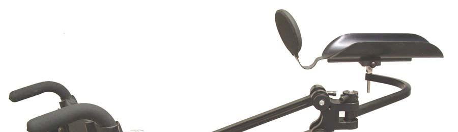
14 4. Slide the Proximal Shaft Collar up the Proximal Shaft. The Proximal Shaft Collar will be used for height and lateral stop adjustment. Do not tighten the Clamp Screw at this time. Note: The Proximal Shaft Collar must be used even if you do not need it to limit the lateral movement of the patient s arm. Proximal Shaft Proximal Shaft Collar 5. With mount attached (page 1-2) to the right side of wheelchair insert Proximal Shaft into the Ball Bearing Housing. Note: Insure the Proximal Shaft protrudes through lower ball bearing. Proximal Shaft Ball Bearing Housing 6. Insert Swivel Stem into the 1/4 inch hole of Distal Arm. 7. Standing in front of the wheelchair, the Multilink Mobile Arm Support should resemble the picture to the right. 8. When optimum adjustments have been made (refer to page 6-1) Secure the settings. 3-2

15 Mobile Arm Support with Elevation Assist Setup Parts Description Left View Elevation Assist Arm Proximal Insert (large 3/8 inch hole) Distal Arm (small 1/4 inch hole) Proximal Shaft Up Stop Collar Level Housing Down Stop Collar Distal Lateral Stop Collar Proximal Shaft Collar Clamp Screw Collar Stop Note: To adjust the position of the Proximal Shaft Collar tighten or loosen the Clamp Screw not the Stop. MultiLink with Elevation Assist Assembly Left Side 1. Lay Multilink Arm on table with Proximal Insert (short end with largest hole) pointing toward you with the Distal Arm pointing to your Right. Note: Multilink arm is designed to be universal Rt or Lt. It is not necessary to remove Arm Link Stops for setup. Proximal Insert Distal Arm 2. Insert Proximal Shaft into through the 3/8 inch diameter hole of the Proximal Insert until the Level Housing rests on top of the arm. Level Housing Proximal Shaft 3. Secure the Proximal Shaft to the arm by tightening the Set Screw using large T-Wrench 3-3 5/16-18x1/4 Set Screw Proximal Insert

 to the left side of wheelchair insert Proximal Shaft into the Ball Bearing Housing.")

16 4. Slide the Proximal Shaft Collar up the Proximal Shaft. The Proximal Shaft Collar will be used for height and lateral stop adjustment. Do not tighten the Clamp Screw at this time. Proximal Shaft Note: The Proximal Shaft Collar must be used even if you do not need it to limit the lateral movement of the patient s arm. Proximal Shaft Collar 5. With mount attached (page 1-2) to the left side of wheelchair insert Proximal Shaft into the Ball Bearing Housing. Note: Insure the Proximal Shaft protrudes through lower ball bearing. Proximal Shaft Ball Bearing Housing 6. Insert Swivel Stem into the 1/4 inch hole of Distal Arm. 7. Standing in front of the wheelchair, the Multilink Mobile Arm Support should resemble the picture to the right. 8. When optimum adjustments have been made (refer to page 6-1) Secure the settings. 3-4
17 Section 4 Basic Adjustments for the Elevation Assist
18 Adjustable Parts Description MultiLinks with Elevation Assist are equipped with an up and down elevation stop. Note the descriptions below then proceed to next page. Collar Clamp Screw Stop Clamp Screw Stop Up or Down Stop attached to Bearing Housing Vertical Stop Pin 4-1


19 Adjusting Down Elevation Right Side Down Elevated Functional Limit 1. Rubber Bands should not be attached when setting stops. 2. While supporting the patient s limb in the lower functional position, loosen the Clamp Screw on the Down Stop Collar using large T-Wrench, rotate the Collar counter clockwise until the Stop rests against the lower side of the Vertical Stop Pin. (see photo to the right) 3. Insert large T-Wrench into the Clamp Screw, then turn clockwise securing the Down Stop in place. Rt Side Inside View Proximal Bearing Housing Enlarged Large T-Wrench Adjusting Up Elevation Right Side Note: To adjust the position of the Proximal Shaft Collar tighten or loosen the Clamp Screw not the Stop. Rt Side Inside View Up Elevated Functional Limit 1. Rubber Bands should not be attached when setting stops. Proximal Bearing Housing Enlarged 2. While supporting the patient s limb in the elevated functional position, loosen the Clamp Screw on the Up Stop Collar using large T-Wrench, rotate the Collar clockwise until the Stop rests against the lower side of the Vertical Stop Pin. (see photo to the right) Large T-Wrench 3. Insert large T-Wrench into the Clamp Screw, then turn clockwise securing the Down Stop in place. 4-2 Note: To adjust the position of the Proximal Shaft Collar tighten or loosen the Clamp Screw not the Stop.


20 Adjusting Down Elevation Left Side Lower Functional Limit 1. Rubber Bands should not be attached when setting stops. 2. While supporting the patient s limb in the lower functional position, loosen the Clamp Screw on the Down Stop Collar using large T-Wrench, rotate the Collar clockwise until the Stop rests against the upper side of the Vertical Stop Pin. (see photo to the right) Left Side Inside View Proximal Bearing Housing Enlarged 3. Insert large T-Wrench into the Clamp Screw, then turn clockwise securing the Down Stop in place. Large T-wrench Adjusting Up Elevation Left Side Note: To adjust the position of the Proximal Shaft Collar tighten or loosen the Clamp Screw not the Stop. Elevated Functional Limit 1. Rubber Bands should not be attached when setting stops. Proximal Bearing Housing Enlarged Lt Side Inside View 2. While supporting the patient s limb in the elevated functional position, loosen the Clamp Screw on the Down Stop Collar using large T-Wrench, rotate the Collar counter clockwise until the Stop rests against the upper side of the Vertical Stop Pin. (see photo to the right) 3. Insert large T-Wrench into the Clamp Screw, then turn clockwise securing the Down Stop in place. 4-3 Large T-wrench Note: To adjust the position of the Proximal Shaft Collar tighten or loosen the Clamp Screw not the Stop.


21 MultiLink with Elevation Assist Rubber Band Setup With Up/Down Stop adjustment completed attach the rubber bands as shown in the pictures below. The rubber bands will be layered upon each other. Note: The weight and muscle tone of the patient s limb will determine the number of rubber bands required to obtain optimum function. Rubber bands supplied contain Dry Natural Rubber. Superior Spool Superior Spool Inferior Spool Inferior Spool Note: These setup instructions are to be used for both Left and Right rubber band attachment. The photo s are of the right outside view. Left side view will look just the opposite. 1. Hook rubber band into the tracks of the Distal and Proximal Inferior Spools. 2. Pinch rubber band and hook into track of Proximal Superior Spool 3. Add more rubber bands as needed to obtain optimum balance. Refer to Section 6 for Basic Adjustments to anterior/posterior and medial/lateral functions 4-4
22 Section 5 Basic Adjustments for Functional Use of the Mobile Arm Support with Elevation Assist


23 Recommendation: Develop an initial comfort level making scroll wheel adjustments without an arm in the MAS. With the MultiLink MAS System attached to the wheelchair, loosen both Lock Knobs A and B just enough to easily turn Scroll Wheel A and Scroll Wheel B. Turn Scroll Wheels A and B separately and also simultaneously. Observe how the adjustments affect the movement of the MAS. Return the Mount to neutral balance using the Bubble Level. Note: Turning the Scroll Wheels tilt the MAS to help the person move in the direction that he/she is weaker. The person must have enough strength to move against the assisted motion. Horizontal Movements: Scroll Wheel A Medial/Lateral Tilt Adjustment Horizontal Stop Pin Ball Bearing Medial/Lateral (side to side) Movements (use Scroll Wheel A): 1. With the person s arm in the MAS, passively move his/her arm as far as possible across the body and then out to the side. This defines the maximum medial-lateral reach area. 2. Ask the person to actively move his/her arm as far as possible from side to side. 3. Observe active movements. Is motion in one direction greater or easier than the other? Consider the work area needed for task performance as you evaluate his/her range of movement. Lock Knob A Jaw Clamp Locking Set Screws Lock Knob B Clamp Screws Scroll Wheel B Anterior/Posterior Tilt Adjustment 4. Adjust for side to side reach. Loosen Lock Knob A and turn Scroll Wheel A in small increments in the direction you want to increase movement. (see photos on the right) Note: The weight of the person s arm must be supported under the forearm support in order to turn the scroll wheels. Mount tilted to assist reach across the body. 5. After each adjustment, ask the person to move his/her arm from side to side and re-adjust until you have the optimum range of movement for his/her needs. Repeated adjustments may be needed during the fitting process. Tighten the Lock Knob to secure the Scroll Wheel after each adjustment. Mount tilted to assist reach to the side. 5-1


24 Anterior/Posterior or Forward Reach/Return Movements (Use Scroll Wheel B): Repeat previous steps #1-5 (page 5-1) but for forward reach and return motions, using Scroll Wheel B. Adjustments made for one movement may affect the other. Scroll wheel B tilted to aid forward reach. Repeat as necessary with both Scroll Wheels A and B obtain the best adjustment for the person s functional needs. The goal is to achieve overall optimal functional range. Readjustments may be needed. Scroll wheel B tilted to aid return motion. Check for clearance: Does the stem of the Offset Swivel hit the wheelchair armrest and/or tabletop or does the elbow dial hit on top of the Distal Arm? If this is a problem, the forearm support may need to be raised by adding a Forearm Support Riser. It may be necessary to re-adjust the height of the Mount. Refer to the Special Circumstances and Alternatives ( page 7-2) if problems are encountered. 5-2
 1. Insert small T-wrench into clamp screw on Stem Collar and rotate counter clockwise to loosen. 2. Slide Stem Collar down the Swivel Stem to obtain optimum clearance.")
 Refer to the \"Special Circumstances and Alternatives (page 8-3) for setup instructions. It may be necessary to re-adjust the height of the Mount.")
25 Check for clearance: Offset Swivel (optional) Does the stem of the Offset Swivel hit the wheelchair armrest and/or tabletop? If this is a problem, the forearm support may need to be raised. To Raise Forearm Support: (Refer to page 2-1 for part descriptions) 1. Insert small T-wrench into clamp screw on Stem Collar and rotate counter clockwise to loosen. 2. Slide Stem Collar down the Swivel Stem to obtain optimum clearance. 3. Insert small T-wrench into clamp screw on Stem Collar and rotate clockwise to tighten. The alternative suspension setup may be necessary. (see photo on right) Refer to the "Special Circumstances and Alternatives (page 8-3) for setup instructions. It may be necessary to re-adjust the height of the Mount. Refer to the Special Circumstances and Alternatives ( page 8-2) if problems are encountered. Document the Functional Working Range: It may help to mark these horizontal tabletop ranges for future reference and comparisons. Different colored marking pens can be used to record differences in range with and without the MAS or with different settings of the MAS. Indicate body midline with an X and use a dotted line for orientation of the paper for reference and comparisons. This dotted line indicates Body Midline Note: Forearm support is shown in suspended setup. 5-3

26 Use of the Proximal Shaft Collar: The Proximal Shaft Collar must always be used. The Proximal Shaft Collar can be used to limit the lateral arm movement, especially if the MultiLink swings out to the side and the person cannot bring it back to the midline work area and to raise the height of the MultiLink Arm if needed. Clamp Screw Stop Collar Note: To adjust the position of the Proximal Shaft Collar tighten or loosen the Clamp Screw not the Stop. How to use the Proximal Shaft Collar as a lateral stop: (read each step) 1. Insure that the set screw on the Proximal Insert of the Elevation Assist Arm is tightened so that it is securely attached to the Proximal Shaft. 2. Loosen the Clamp Screw on the Proximal Shaft Collar to allow it to rotate freely on the Proximal Shaft. 3. Ask the person to actively move his/her arm as far to the side as possible while still being able to bring it back to the center. (If the lateral movement needs to be restricted, the lateral stop function is needed.) 4. To set the lateral stop function, position the Elevation Assist Arm and the Distal Arm at the end range of the desired lateral movement. 5. Move the Proximal Shaft Collar so that the Stop rests against the back Horizontal Stop Pin on the mount at this established end range. (see photo at right) 6. Next move the Distal Lateral Stop Collar so that the Stop rests against the Horizontal Stop Pin on the Distal Insert at this established end range. (see photo at right) 7. Tighten the Clamp Screw on the Proximal Shaft Collar in this position. 8. Check the Stop position by asking the person to move his/her arm to the side. The person should be able to return arm to the midline work area. Set Screw Proximal Insert Distal Arm 5-4 Distal Insert
 Is the person s elbow centered on the elbow dial when hand is near the mouth?")

27 Hand to Mouth Movements: Mobile Arm Supports with Slide only: 1. With the person s arm in the Forearm Support, passively move the person s hand from tabletop to his/her mouth. Can hand reach the mouth? Does the elbow dial hit the laptop or tabletop? (review check for clearance page 5-2) Is the person s elbow centered on the elbow dial when hand is near the mouth? Bend the elbow dial as necessary to center the elbow 2. Ask the person to actively bring his/her hand to their mouth. If he/she has difficulty, instruct the person to push down with his/her shoulder or to move their elbow down and inward toward their body. This causes the elbow to push down on the elbow dial and brings the hand to the mouth. Ask the person to relax the shoulder to bring the hand down to the tabletop. 3. Determine which motion is more difficult. 4. Adjust the Slide to Assist Hand to Mouth Movements: Note: During functional adjustments, it is not necessary to remove the person s arm from the forearm support. Bend the person s elbow so full arm weight is not on the slide mechanism, but on the elbow dial. Support the weight of the person s forearm with one hand under the elbow dial; move the adjustable slide with the other hand. Assist hand to mouth motions by moving the Adjustable Slide. (see photos below). Moving the slide toward the wrist usually aids the up motion. Moving the slide toward the elbow usually aids the down motion. Slide positioned so forearm support is balanced. Slide moved forward to aid the up motion. (exaggerated for effect) Slide moved back toward elbow to aid the down motion. (exaggerated for effect) 5-5


.")

28 Offset Swivel (optional) Check Alignment of the Offset Swivel Pin. Change position only if needed. In most cases, the manufacturer s setting will be adequate. Note the recommended position of the Offset Swivel Pivot Pin in the photo on the right. Movement is easier if the Pivot Pin is slightly lower rather than higher than this mid-position. This mid-position usually allows easy pivoting motions without excess shoulder hiking. If the position of the Pivot Pin needs to be changed: 1. Remove the Forearm Support assembly from the MultiLink. 2. Detach the offset swivel from the L-bar. (Firmly hold the L-bar and press out the pin with your thumb(s). If difficult, remove the forearm support from the L-bar (remember to loosen the distal screw to slide off). Stabilize the inside pivot pin against a flat stable surface and press down on the L-bar. (see photos below). 3. Reattach the pin in the desired hole by firmly pressing pin into the hole. The Pivot Pin must be inserted all the way through. Note: The Down Stop should be on the front side of the L-bar for Right side setup and rear of the L-bar for Left side setup. Refer to page 5-7 Pressing out pivot pin with thumbs. Pressing out pivot pin against table surface. Reattaching L-bar with Down Stop in front. 5-6
 Is the person s elbow centered on the elbow dial when hand is near the mouth?")


29 Hand to Mouth Movements: Offset Swivel (optional) 1. With the person s arm in the Forearm Support, passively move the person s hand from tabletop to his/her mouth. Can hand reach the mouth? Does the elbow dial hit the laptop or tabletop? (review check for clearance page 5-2) Is the person s elbow centered on the elbow dial when hand is near the mouth? Bend the elbow dial as necessary to center the elbow 2. Ask the person to actively bring his/her hand to their mouth. If he/she has difficulty, instruct the person to push down with his/her shoulder or to move their elbow down and inward toward their body. This causes the elbow to push down on the elbow dial and brings the hand to the mouth. Ask the person to relax the shoulder to bring the hand down to the tabletop. 3. Determine which motion is more difficult. 4. Adjust the Slide to Assist Hand to Mouth Movements: Note: During functional adjustments, it is not necessary to remove the person s arm from the forearm support. Bend the person s elbow so full arm weight is not on the slide mechanism, but on the elbow dial. Support the weight of the person s forearm with one hand under the elbow dial; move the adjustable slide with the other hand. Assist hand to mouth motions by moving the Adjustable Slide. (see photos below). Moving the slide toward the wrist usually aids the up motion. Moving the slide toward the elbow usually aids the down motion. Slide positioned so forearm support is balanced. Slide moved forward to aid the up motion. (exaggerated for effect) Slide moved back toward elbow to aid the down motion. (exaggerated for effect) 5-7


: Down Stop rests against the top/front of the L-bar to limit the down motion")
30 Down Stop: Offset Swivel (optional) Setting the Down Stop: The Down Stop limits the downward motion and makes it easier for the person to bring their hand back up to their mouth. Loosen (do not remove) the Clamp Screw on the Down Stop Collar using the large T-Wrench to allow pivotal movement of the offset swivel. (Refer to page 2-1) Note: The Down Stop should not hit against the L-bar during up motions. If the Down Stop function is needed to limit the down motion: 1. Position the forearm support in the maximum down position desired. 2. Rotate the Collar until the Down Stop rests against the L-bar and blocks further downward motion, see photos below. (The Down Stop will hit the L-bar on the top/front for the Right side setup and bottom/rear for Left side setup.) 3. Tighten the Clamp Screw in this position to set the stop" function. Right side (close up, inside): Down Stop rests against the top/front of the L-bar to limit the down motion Left side (close up, inside): Down Stop rests against the bottom/rear of the L-bar to limit the down motion Offset Swivel Assembly, Right Side Offset Swivel Assembly, Left Side 6. Raise the Forearm Support, as needed. It may be necessary to raise the forearm support by moving the stem collar to a lower position. (Refer to page 5-2) To Raise Forearm Support. 5-8
31 Section 6 Finalizing Setup
 Make re-adjustments as necessary to achieve normal shoulder height. (It may be necessary to lower the mount placement.")

32 Check Overall Setup Again, observe the person s shoulders to be sure they are at a comfortable, level, resting position. (If the person is uncomfortable, MAS wear time and use will be limited.) Make re-adjustments as necessary to achieve normal shoulder height. (It may be necessary to lower the mount placement.) Refer to the Special Circumstances and Alternatives section if mount placement is a problem. Secure the Settings After evaluating the MAS use with a variety of functional activities, and when you are satisfied with the adjustments, secure the settings. Using the small T-Wrench tighten the Locking Set Screws on the MAS Mount to secure it to the wheelchair upright. The pointed end of these lock screws will pierce fabric and/or metal. Insure all knobs and screws are tight. Locking the Mount in Place When optimal functional use of the mobile arm support is achieved, tighten the Locking Set Screws using the small T-Wrench. This will lock the mount in its position on the wheelchair upright (back post). Mark the Settings Mark the settings when you are satisfied with the adjustments. Mark scroll wheels, mount position, stem position, etc. See photos below. When marked, it is easy to match up the marks and return to your desired settings if parts get out of alignment or moved. Correction fluid works well on the black for initial adjustments because it can be removed with a damp cloth. Nail polish can be used for a more permanent marking. Different settings might be desired for varied activities such as keyboard activity or feeding; markings can be color coded. Marks on the W/C upright and also on the mount make it easy to realign the pieces, if moved. Locking Set Screws Line markings on the forearm support or stem make it easy to find the correct Position for various activities HOW TO REMOVE THE MAS FOR TRANSPORT: Lift the Offset Swivel stem up and out of the distal link. Lift the Proximal Shaft up and out of the Mount. (leave MultiLink attached to the shaft) Place the MAS parts in a protective bag to protect the black anodized covering from scratches. Leave the Mount on the wheelchair. 6-1
33 Section 7 Special Circumstances and Alternatives

. If this occurs, do not use this setup.")
34 MAS Mount Attachment Problems: Alternative Mount Attachment: Invert the mount (turn it over). Clamp Screws face toward the back of wheelchair and Lock Knob A faces front. Clamp Screws are easier to reach for tightening and adjusting in this position. LEFT Side (Front of wheelchair) View from Above RIGHT Side (Front of wheelchair) (Back of wheelchair) (Back of wheelchair) Depending upon location of the mount attachment, Lock Knob A might cause pressure against the back of the person s upper arm when their forearm is resting on the wheelchair armrest and not in the MAS. (See photo on right). If this occurs, do not use this setup. Alternative Mount Setup If this happens, use the regular Mount setup with the Lock Knob A facing to the back and the Clamp Screws facing to the front. This should make it more comfortable for the person when not using the MAS. 7-1 Regular Mount Setup


35 If the Mount still rests against the upper arm, it can be mounted at an angle. Scroll Wheel A will no longer be just for Side to Side adjustments, and Scroll Wheel B will no longer be just for Forward/Return adjustments. Combined Scroll Wheels A and B adjustments will be necessary. If the Proximal Shaft hits the W/C armrest and cannot be fully inserted: Attach the mount at an angle as described above. If the mount is too low: The Mobile Arm Support can be raised slightly and secured by lowering the Proximal Shaft Collar on the Proximal Shaft and re-tightening the Clamp Screw. Insure the Set Screw on the Proximal Insert is tightened to secure the Elevation Assist Arm to the Proximal Shaft. (This modification is not recommended for those with heavy arms or increased tone because of the added stress on the shaft and mount.) The shaft must protrude through the bottom ball bearing on the mount. The person s arm can be raised to compensate for a low placed mount by adding a Forearm Support Riser. Or if using an Offset Swivel, lower the Stem Collar on the Swivel Stem. 7-2
 Insert the Swivel Stem of the Offset Swivel from the bottom up and secure with the Stem Collar on top.")

36 If the mount is too high and can only be mounted above the person s mid-humeral level, the Forearm Support may need to be lowered by suspending the Forearm Support. Suspending Forearm Support: MAS with Offset Swivel (optional) Insert the Swivel Stem of the Offset Swivel from the bottom up and secure with the Stem Collar on top. If this setup is used, do not constantly remove the Stem Collar. It is recommended that the MAS system be kept as one unit if removed from the mount for storage or transport. As one unit, the MAS is less compact for fitting in a wheelchair backpack for transport but easier for setup. 1. Remove the Stem Collar on the Offset Swivel. 2. Insert the Offset Swivel Stem from bottom up. 3. Secure with the Stem Collar on the top. 4. Raise the Mount or MAS. 5. Readjust MAS as needed for optimum patient functioning. If the mount cannot be attached with the Scroll Wheel A in line with the W/C armrest: It is possible to attach the Mount at an angle. Combined adjustments of the Scroll Wheels A and B will allow for medial/lateral and anterior/posterior movements. Scroll Wheel A in line with the WC armrest Mount attached at an angle Mount attached at an angle (top view) (top view) (front view) When the shape of the wheelchair upright, its position or obstructions from other equipment attached to the upright do not allow for optimal mount positioning a Mount Relocator (section 9) should be used. 7-3

37 Problems with Clearance of Elbow Dial or Swivel Stem : Does the elbow dial hit on top of the Distal Arm or does the stem of the Offset Swivel (optional) hit the wheelchair armrest and/or tabletop? If this is a problem, the forearm support may need to be raised by adding a Forearm Support Riser. Move the adjustable slide under the forearm support back 1 to 2 notches toward the elbow. This will only work if the person can still easily move their hand up and down after the adjustment. Raise the forearm support by lowering the Stem Collar on the offset Swivel Stem and tightening the Clamp Screw. (Offset Swivel optional) Refer to page 5-3 Try the alternative Suspension Set-up: (Offset Swivel optional) 1. Remove the Stem Collar on the Offset Swivel. 2. Insert the Offset Swivel Stem from bottom up. 3. Secure with the Stem Collar on the top. 4. Raise the Mount or MAS. 5. Readjust MAS as needed for optimum patient functioning. Funded by National Institute for Disability & Rehabilitation Research (NIDRR Grant #H133E003001) Developed by Rehabilitation Engineering Research Center on Technology for Children with Orthopedic Disabilities Rancho Los Amigos National Rehabilitation Center 7-4
38 Section 8 JAECO Mount Relocators
39 Mount Relocator For Mounting to Wheelchairs with Tubular Back Posts Features: The unique design of the Mount Relocator has several advantages over our previous Bracket Relocator. The new Mount Relocator clamps onto ¾ inch to 1 inch tubing. Clamps over back posts (wheelchair uprights) enclosed in fabric without having to remove the fabric from the mounting area. The 10 inch long mounting shaft and articulated arms of the Mount Relocator allow for optimum Mobile Arm Support mount position. The Clamp Mount Base requires only 1.5 inches to mount to the wheelchair back post (wheelchair upright). The solid anodized black aluminum construction minimizes deflection. This Mount Relocator even with the Mobile Arm Support attached can be removed and replaced quickly by the turn of a knob, without losing it s preset adjustments. 8-1
40 Standard Setup Left Assembly Viewed from back side of wheelchair Right Assembly Alternate Setup Left Alternate Setup Right Alternate Setup Preparation 1. Locate and mark on the back post (wheelchair upright) the patient s mid humeral area. Note: The mount base needs to be attached a minimum of approximately 5 inches above or 8 inches below this mid humeral location. Alternate arm setup will decrease the amount of clearance needed when attached above marked location. See Alternate Setup images above. 2. If the relocator Mount Base is attached to the Mount Relocator, loosen Locking Knob and remove the Mount Base. 3. Loosen, Do not remove, Clamp Screws using large T-Wrench. Push floating clamp forward and outward. 8-2 Mount Base Locking Knob Clamp Screws
 as specified in Preparation Instructions page 9-2 and tighten Clamp Screws just enough so it is snug but will still rotate on the")
41 Mounting 1. Attach relocator Mount Base to location on back post (W/C upright) as specified in Preparation Instructions page 9-2 and tighten Clamp Screws just enough so it is snug but will still rotate on the back post. This rotation may be necessary for relocator arm alignment. Clamp Screws Viewed from front of wheelchair Right side pictured 2. Loosen, Do Not Remove, all six Clamp Screws on relocator arm. Insert the Mount Relocator into the Mount Base and insure the Pin in the Arm Shaft inserts into the Slot on the top of the Mount Base then tighten Locking Knob. Clamp Screws Mount Base Slot Locking Knob Pin Arm Shaft Finalizing Setup 1. Align the Mount Shaft with patient s back by adjusting the Relocator arms. Mount Shaft 2. Attach the Mobile Arm Support mount (bracket) to the Mount Shaft and align the top bearing of the mount with the mid humeral location of the patient s arm. 3. When optimum position is acquired tighten all eight Clamp Screws using large T-Wrench. 4. When final mount (bracket) position is obtained then tighten all five Locking Set Screws using small T-Wrench to secure relocators position. Note: It is recommended that the Locking Set Screws only be used once, when all adjustments are completed. Tightening and readjusting these screws can cause Viewed from damage to the Relocator Arm Pin. front of wheelchair Locking Set Screws Clamp Screws Right side pictured 8-3

42 Mount Relocator For Mounting to Wheelchairs with Molded Back Rests when back posts are restricted or not present Features: The unique design of this Mount Relocator is that it can attach to plastic or metal wheelchair backrests when back posts are restricted or not present. The 10 inch long mounting shaft and articulated arms of the Mount Relocator allow for optimum Mobile Arm Support mount position. The Mount Base requires only 3 inches to mount to the wheelchair backrest. The solid anodized black aluminum construction minimizes deflection. This Mount Relocator, even with Mobile Arm Support attached, can be removed and replaced quickly by the turn of a knob, without losing it s preset adjustments. 8-4
43 Standard Setup Left Assembly Right Assembly Alternate Setup Left Alternate Setup Right Alternate Setup Preparation 1. If the relocator Mount Base is attached to the Mount Relocator, loosen Locking Knob and remove the Mount Base. 2. Remove the two Attachment Screws and Reinforcement Washer from the Mount Base 3. Remove backrest cushion. 4. Place template on back of backrest 1.5 to 2 inches down from inner edge and over 2.5 inches from outside edge and mark template holes. Note: Place Base Drill Template on flattest area of backrest 5. Use drill bit supplied and drill the two marked holes. Mount Base Attachment Screw Reinforcement Washer Top Edge Approx. 2.5 inches Down Right Side Attachment Back View Locking Knob Side Edge Approx. 2.5 inches Over Base Drill Template Right back view 8-5
44 Mounting Attached view 1. Insert Screw and washer through hole on cushion side of backrest and use large T-Wrench to tighten into Mount Base. Mount Base Mount Base Slot 2. Loosen, Do Not Remove, all six Clamp Screws on relocator arm. Insert the Mount Relocator into the Mount Base and insure the Pin in the Arm Shaft inserts into the Slot on the top of the Mount Base then tighten Locking Knob. Locking Knob Clamp Screws Finalizing Setup Right side attachment 1. Align the Mount Shaft with patient s back by adjusting the relocator arms. Note: Alternate arm setup will increase Mount shaft height if needed. See Alternate Setup Page 9-5. Locking Set Screws Mount Shaft 2. Attach the Mobile Arm Support mount (bracket) to the Mount Shaft and align the top bearing of the mount with the mid humeral location of the patient s arm. 3. When optimum position is acquired tighten all six Clamp Screws using large T-Wrench. 4. When final mount (bracket) position is obtained then tighten all three Locking Set Screws using small T-Wrench to secure relocators position. Note: It is recommended that the Locking Set Screws only be used once, when all adjustments are completed. Tightening and readjusting these screws can cause damage to the Relocator Arm Pin. 8-6 Viewed from back of wheelchair Right side pictured Clamp Screws
 for some Invacare, Motion Concepts and other seating systems.")

45 Mount Relocator For Mounting to Wheelchairs with Keyed Back Posts Features: The unique design of the Mount Relocator has several advantages over our previous Bracket Relocator. This Mount Relocator attaches to Keyed Back Canes (W/C upright) for some Invacare, Motion Concepts and other seating systems. The 10 inch long mounting shaft and articulated arms of the Mount Relocator allow for optimum MAS mount position. The Mount Base requires only 1.5 inches to mount to the Keyed Back Cane. The solid anodized black aluminum construction minimizes deflection. This Mount Relocator, even with the Mobile Arm Support attached, can be removed and replaced quickly by the turn of a knob, without losing it s preset adjustments. 8-7
46 Standard Setup Left Assembly Right Assembly Alternate Setup Left Alternate Setup Right Alternate Setup Preparation 1. Locate and mark on the Keyed Back Cane of the wheelchair the patient s mid humeral area. Note: The mount base needs to be attached a minimum of approximately 5 inches above or 8 inches below this mid humeral location. Alternate arm setup will decrease the amount of clearance needed when attached above marked location. See Alternate Setup images above. 2. If the relocator mount base is attached to the Mount Relocator, loosen Locking Knob and remove the mount base. 3. Remove the Slotted Mount Block from the Mount Adapter by inserting large T-Wrench into Attachment hole and turning counter clockwise. 4. Locate and remove the plastic cap from the top of the Keyed Back Cane of the wheelchair. Mount Base Locking Knob T-Nut Mount Adapter Slotted Mount Block Attachment Hole 8-8


47 Mounting T-Nut 1. Loosen, Do not remove, Mount Adapter T-Nut Screws using large T-Wrench. Mount Adapter 2. Insert T-Nut and Mount Adapter into Keyed Back Cane channel and position Mount Adapter above or below marked location as specified in Preparation instructions page 9-8 then tighten the two T-Nut screws. Note: It will be necessary to remove Spreader Bar (bar that links both Keyed Back Posts) to attach the Mount Adapter below and sometimes above the marked location. To do this: Loosen, Do not remove, all four Spreader Bar bolts using 7/16 inch wrench and slide bar out of Keyed Back Posts. 3. Attach Slotted Mount Block by inserting large T-Wrench with screw into Attachment Hole and turning hex wrench clockwise. Note: If Spreader Bar was removed, reattach Spreader bar, secure in place, and insert the plastic cap that was removed in step 4 of Preparation instructions page Loosen, Do Not Remove, all six Clamp Screws on relocator arm. Insert the Mount Relocator into the Mount Base and insure the Pin in the Arm Shaft inserts into the Slot on the top of the Mount Base then tighten Locking Knob. Keyed Back Post Slotted Mount Block Step 3 Right Attachment Pictured Step 2 Attachment Hole Pin Mount Base Slot Locking Knob T-Nut Screws Step 4 Arm Shaft Finalizing Setup 1. Align the Mount Shaft with patient s back by adjusting the Relocator arms. 2. Attach the Mobile Arm Support mount (bracket) to the Mount Shaft and align the top bearing of the mount with the mid humeral location of the patient s arm. 3. When optimum position is acquired tighten all six Clamp Screws using large T-Wrench 4. When final mount (Bracket) position is obtained then tighten all three Locking Set Screws using small T-Wrench to secure relocators position. Note: It is recommended that the Locking Set Screws only be used once, when all adjustments are completed. Tightening and readjusting these screws can cause damage to the Relocator Arm Pin. 8-9 Right side attachment viewed from back of wheelchair Clamp Screws Mount Shaft Locking Set Screw
48 Parts Description For Mount Relocators No. Qty. Part No. Description 1 1 MRB-10 MR-10 Mount Base 2 1 MRB-7 MR-7 Mount Base 3 1 MRB-8 MR-8 Mount Base 4 1 MR1SMB Slotted Mount Block 5 1 K1420x916x1BP Locking Knob 6 1 MR1BCA Base Clamp 7 1 MR1FC Floating Clamp 8 2 BHSCS1428x112A Clamp Screw 9 2 SSSCNP1032x316A Locking Set Screw 10 1 BHSCS1420x1A Mount Base Screw 11 2 MR7W1 Aluminum Washer 12 1 MR7MBA MR-7 Mount Base Adapter 13 1 MR8TNUT MR-8 T-Nut w/ Screws 14 1 MR8MBA MR-8 Mount Base Adapter 15 1 MR1AMS Arm Mount Shaft 16 1 MR1AC Arm Clamp 17 1 MR1ARM4 4" Arm 18 1 MR1JP Joint Pin 19 1 MR1ARM6 6" Arm 20 1 MR1MS10 Mount Shaft 21 1 MR1MSB Mount Shaft Base 22 3 SSSCNP1032x316A Locking Set Screw 23 6 BHSCS1420x1A Clamp Screw 24 2 BHSCS1420x12A Mount Shaft Screw 25 5 RRE78A External Retaining Ring : MR-10 Mount Base 2: MR-7 Mount Base 3: MR-8 Mount Base 8-10
49 Notes:
Setup Instructions for MultiLink Mobile Arm Supports
 Setup Instructions for MultiLink Mobile Arm Supports January 1, 2005 Revised May 27, 2008 Table of Contents Section 1: Mobile Arm Support Mounts Section 2: Forearm Support with Offset Swivel & Slide Section
Hardware and Components:
 Hardware and Components: (A) 5/16 x 2 Hex Bolt (B) 5/16 x 2-1/4 Hex Bolt (C) 5/16 x 2-1/2 Hex Bolt (D) 4X 5/16 x 3/4 Hex Bolt (E) 4X 5/16 x 1-1/4 Hex Bolt (F) 11X 5/16 Flat Washer (G) 12X 5/16 Nylock Nut
Hardware and Components:
 Hardware and Components: (A) 4X 5/16 x 1 Carriage Bolt (B) 2X 5/16 x 2-1/4 Carriage Bolt (C) 2X 5/16 x 3-1/4 Hex Bolt (D) 2X 5/16 x 3/4 Hex Bolt (E) 2X 5/16 x 1-1/4 Hex Bolt (F) 5/16 x 2-1/4 Hex Bolt (G)
EZ-Lock Assembly Manual
 ABM International, Inc. EZ-Lock Assembly Manual 1 ABM International, Inc. Series: 1018/1022/1026 V1.0 EZ-Lock Parts List - Structural frame profiles Slotted beam: (Qty. 2) 15.75 Commercial Parts - Liner
MM340 Installation Instructions IMPORTANT SAFETY INSTRUCTIONS - SAVE THESE INSTRUCTIONS
 MM30 Installation Instructions IMPORTANT SAFETY INSTRUCTIONS - SAVE THESE INSTRUCTIONS Please read this entire manual before you begin. Do not unpack any contents until you verify all requirements on PAGE.
MantelMount. TM1A Installation Instructions IMPORTANT SAFETY INSTRUCTIONS - SAVE THESE INSTRUCTIONS
 MantelMount TMA Installation Instructions IMPORTANT SAFETY INSTRUCTIONS - SAVE THESE INSTRUCTIONS TM Thank you for choosing the MantelMount television wall mount. Please read this entire manual before
PORTABLE ADJUSTABLE BASKETBALL SYSTEM
 Instruction Manual PORTABLE ADJUSTABLE BASKETBALL SYSTEM P A R T S L I S T 5 1/2 and 8 safe play clearance Item Qty Description Item Qty Description A 1 Portable Base Assembly M 4 1/2 Lock Nut B 2 Front
MM540 Installation Instructions IMPORTANT SAFETY INSTRUCTIONS - SAVE THESE INSTRUCTIONS
 MM50 Installation Instructions IMPORTANT SAFETY INSTRUCTIONS - SAVE THESE INSTRUCTIONS Please read this entire manual before you begin. Do not unpack any contents until you verify all requirements on PAGE.
MODEL 200/220 ASSEMBLY INSTRUCTIONS
 V-Twin MFG. Coats Tire Changer VT Part No. 16-0510 This tool should only be used by a knowledgeable and trained motorcycle technician V-Twin Mfg. accepts no responsibility for improper use. MODEL 200/220
High Rise Sit-Stand Desk Converter
 High Rise Sit-Stand Desk Converter Assembly Instructions for Model DC300 Patent Pending PRE-ASSEMBLY Please read all instructions before beginning assembly. We strongly recommend you watch the video at
High Rise Sit-Stand Desk Converter
 High Rise Sit-Stand Desk Converter Assembly Instructions for Model DC350 Patent No. 9,332,839 PRE-ASSEMBLY Please read all instructions before beginning assembly. We strongly recommend you watch the video
BY ALIEN TECHNOLOGIES CORP
 BY ALIEN TECHNOLOGIES CORP Assembly Instructions TopLift Pros YOU MAY ALSO REVIEW OUR ASSEMBLY VIDEO, PLAY AND PAUSE AT YOUR CONVENIENCE. JUST VISIT US AT WWW.TOPLIFTPROS.COM AND GO TO Customer Support
MM750 Installation Instructions
 MM750 Installation Instructions IMPORTANT SAFETY INSTRUCTIONS - SAVE THESE INSTRUCTIONS Please read this entire manual before you begin. Do not unpack any contents until you verify all requirements on
TABLE OF CONTENTS REQUIRED TOOLS
 TABLE OF CONTENTS SECTION SECTION TITLE PAGE NO. 1 2 3 4 5 Assembling Mounting Structure Installing Bicycle Supports Mounting Rack to Wall Adding Sections Customizing Rack Configuration REQUIRED TOOLS
Lumber Smith. Assembly Manual. If you are having problems assembling the saw and need assistance, please contact us at:
 Lumber Smith Assembly Manual If you are having problems assembling the saw and need assistance, please contact us at: 804-577-7398 info@lumbersmith.com 1 Step 1 Safety Carefully read the Owners Manual.
TOOL LIST FOR TAILGATE HIDDEN LATCH & LINK ASSY FOR FORD FLARESIDE TRUCKS
 TOOL LIST FOR TAILGATE HIDDEN LATCH & LINK ASSY FOR 53-87 FORD FLARESIDE TRUCKS Vise Grip Clamps C-clamps Sharpie Marker Ball Peen Hammer Center Punch 3/8 or 1/2 Drill 5/32, 7/32, 9/32, and 3/8 Drill Bits
Strata. urniture. Adriana Instructions. Parts in the Arm Box: Parts in the Body Box: Watch our assembly videos at
 1A Watch our assembly videos at www.strataf.com/videos Parts in the Arm Box: Arm - Outside View Arm - Inside View 1B Parts in the Body Box: Back Deck x 1 Seat Deck x 1 with the Feet attached Back Panel
Installation Instructions Universal Crossmember Kit - 60 Track Width BEFORE Measure Twice, Weld Once! II
 Installation Instructions Universal Crossmember Kit - 60 Track Width Please read these instructions completely BEFORE starting your installation. Remember the basic rule for a successful installation:
Due to possible damage in shipping, the vertical stop assembly has been removed from this machine.
 Due to possible damage in shipping, the vertical stop assembly has been removed from this machine. To assemble, insert the threaded rod through the shroud opening in the top of the machine. Start the four
Gared Pro-S Portable Backstop
 Models: 9616 & 9618 Installation, Operation and Maintenance Instructions Please read all instructions before attempting installation or operation of these units SAVE THESE INSTRUCTIONS FOR FUTURE USE PUBLICATION
LifeGear G1 /HOME GYM ITEM NO.: 63100
 LifeGear G1 /HOME GYM ITEM NO.: 63100 OWNER S MANUAL IMPORTANT: Read all instructions carefully before using this product. Retain this owner s manual for future reference. The specifications of this product
BEAST THE. Tube and Pipe Notcher Operating Instructions. Notches In Bends Straight Notches. Angled Notches. Offset Notches
 Copyright (c) 2007 J D SQUARED INC. www.jd2.com THE BEAST Tube and Pipe Notcher Operating Instructions Notches In Bends Straight Notches Angled Notches PATENT PENDING Offset Notches Assembly After unpacking
Hollywood Swing Away 2 and 4 Bike Racks Assembly and Installation Guide
 Hollywood Swing Away 2 and 4 Bike Racks Assembly and Installation Guide Tools Required: two adjustable wrenches, pliers, ¾ socket wrench recommended Note: please do assembly near your vehicle as you Can
Adjusting 45 Compass Hardware Including 4-Point
 Adjusting 45 Compass Hardware Including 4-Point Compass Hardware - US Patent No. 7,104,610 & 7,891,739 Apparatus for Mounting a Wheelchair Back Quick Release Fixed 4-Point The information in this manual
Electric Skein Winder
 Electric Skein Winder Assembly and Use Package Contents 1 - Triangular Body (w/ motor) 1 - Cross Arm 1 - Left Foot (w/ yarn guide) 1 - Right Foot 1 - Adjustable Finger (w/ yarn clip) 3 - Adjustable Fingers
Page 1. SureMotion Quick-Start Guide: LACPACC_QS 1st Edition - Revision A 03/15/16
 R K C T I Repair Kit Product Compatibility Repair Kit # Linear Actuator Assembly # LACPACC-002 LACPACC-003 LACP-16TxxLP5 (0.5-in lead screw pitch) LACP-16TxxL1 (1-in lead screw pitch) C P I R K 4 ea Flanged
Nancy s Knit Knacks LLC 4 Yard Option Upgrade Kit Assembly Instructions and User Manual
 Nancy s Knit Knacks LLC 4 Yard Option Upgrade Kit Assembly Instructions and User Manual Thank you for purchasing our 4 Yard Option (4YO) Upgrade Kit. To install this upgrade you are simply going to assemble
For additional assistance call
 The following pages will help guide you through the process of assembling your new 48 custom prize wheel. Choose an assembly area with plenty of room to lay your pieces on the floor and also a bench or
Installation and Assembly - Universal Articulating Swivel Double-Arm for 42" - 60" Plasma Screens
 Installation and Assembly - Universal Articulating Swivel Double-Arm for 42" - 60" Plasma Screens Models: PLAV 70-UNL, PLAV 70-UNL-S PLAV 70-UNLP, PLAV 70-UNLP-S R This product is UL Listed. It must be
Usage and Assembly Instructions
 Instructions #1037447 Product #795234 Revision C Usage and Assembly Instructions Rear Fork (Buttstock) Rear Fork Lock Knob Rail Lock Knob Front Fork (Forend) Rails Tilt Friction Knob Rail Extension Locks
PFT CABLE GYM INSTRUCTION MANUAL
 PFT CABLE GYM INSTRUCTION MANUAL QUESTION? As a quality home gym supplier we are committed to your complete satisfaction. If you have questions, or find missing or damaged parts, we will guarantee your
Installation and Assembly - Universal Articulating Swivel Double-Arm for 42" - 60" Plasma Screens
 Installation and Assembly - Universal Articulating Swivel Double-Arm for 42" - 60" Plasma Screens Models: PLAV 70-UNL, PLAV 70-UNL-S PLAV 70-UNLP, PLAV 70-UNLP-S R This product is UL Listed. It must be
Wooden Frame Type Instruction Manual
 Wooden Frame TypeInstruction Manual Thank you for selecting our product. Before starting installation, please read this manual thoroughly to ensure correct installation. Please keep this manual at hand
Replacing the Reciprocator on the SWF Compact Series Machine (601C and 1201C)
") Follow the instructions below to replace the reciprocator in the SWF Compact series machines. The tools required can be found in the tool kit that came with the machine. Preparation 1. First, place the
Follow the instructions below to replace the reciprocator in the SWF Compact series machines. The tools required can be found in the tool kit that came with the machine. Preparation 1. First, place the
Usage and Assembly Instructions
 Instructions #1037447 Product #795234 Revision D Usage and Assembly Instructions Rear Fork (Buttstock) Rear Fork Lock Knob Rail Lock Knob Front Fork (Forend) Rails Tilt Friction Knob Rail Extension Locks
Heavy Duty Ceiling Tilt Mount Installation Manual
 HD-CTM-5580 Heavy Duty Ceiling Tilt Mount Installation Manual *This Installation requires a minimum of two people. For your safety: Read the complete instruction manual before starting an installation
Contractors Rack Assembly and Installation Instructions
 Part # 18601 & 16601 Contractors Rack Assembly and Installation Instructions 4751 Littlejohn St. Unit A, Baldwin Park, CA 91706 Page 1 of 12 11/13/08 Thank you for purchasing the Paramount Restyling Contractors
Inventory MODEL T10096 TAPER ATTACHMENT FOR G0509 & G0509G LATHE INSTRUCTIONS. Inventory (Figure 1) Needed Items
 Needed Items") MODEL T10096 TAPER ATTACHMENT FOR G0509 & G0509G LATHE INSTRUCTIONS Inventory The Model T10096 taper attachment was carefully packed when it left our warehouse. If you discover it is damaged after you
MODEL T10096 TAPER ATTACHMENT FOR G0509 & G0509G LATHE INSTRUCTIONS Inventory The Model T10096 taper attachment was carefully packed when it left our warehouse. If you discover it is damaged after you
HDL(M)6 Nut/Screw Assembly
6 Nut/Screw Assembly") HDL(M)6 Nut/Screw Assembly Remove, repair, and reassemble the nut and screw assembly in your HDL series double lock vise. In these instructions when we refer to the front of the vise or nut/screw assembly,
HDL(M)6 Nut/Screw Assembly Remove, repair, and reassemble the nut and screw assembly in your HDL series double lock vise. In these instructions when we refer to the front of the vise or nut/screw assembly,
USSC LLC 4 ONE LLC FIELD MODIFICATION INSTRUCTIONS
 1 OF 17 A 1. PURPOSE: Instructions for in field replacement of 9004 mechanical suspension top pan 2. SCOPE: 9004 mechanical suspension with legacy two point LX back frame and current LX back frame 3. PROCEDURE:
1. Turn off or disconnect power to unit (machine). 2. Push IN the release bar on the quick change base plate. Locking latch will pivot downward.
. 2. Push IN the release bar on the quick change base plate. Locking latch will pivot downward.") Figure 1 Miniature Quick Change Applicators, of the end feed type, are designed to crimp end feed strip terminals to prestripped wires. Each applicator is set up to accept the strip form of certain specific
Figure 1 Miniature Quick Change Applicators, of the end feed type, are designed to crimp end feed strip terminals to prestripped wires. Each applicator is set up to accept the strip form of certain specific
PARTS INCLUDED IN FIXED STAIR CABLE RAIL KIT:
 175 SERIES FIXED STAIR CABLE RAIL - INSTALLATION INSTRUCTIONS PARTS INCLUDED IN FIXED STAIR CABLE RAIL KIT: FIXED STAIR TOP RAIL (1) A FIXED STAIR BOTTOM RAIL (1) B D UPPER SADDLE BRACKET (1) C BRACKET
ABM International, Inc. Navigator Assembly Manual
 ABM International, Inc. 1 1.0: Parts List Tablet (Qty. 1) Tablet mount (Qty. 1) NOTE: Mount may appear and operate different then image below Control Box (Qty. 1) Motor Power Supply (Qty. 1) 2 X-axis motor
STEINBERGER TRANSTREM (TYPE 2) TECHNICAL DOCUMENT
 TECHNICAL DOCUMENT") STEINBERGER TRANSTREM (TYPE 2) TECHNICAL DOCUMENT These instructions apply to newer style TransTrems only (non-threaded ball type or modified threaded ball type). For purposes of discussion, these TransTrems
STEINBERGER TRANSTREM (TYPE 2) TECHNICAL DOCUMENT These instructions apply to newer style TransTrems only (non-threaded ball type or modified threaded ball type). For purposes of discussion, these TransTrems
Strata. urniture. Mission Rim Instructions. Parts in the Arm Box: Parts in the Body Box:
 1A Watch our assembly videos at www.strataf.com/videos.html Parts in the Arm Box: Arm - Outside View Arm - Inside View Corbels x 4 1B Parts in the Body Box: Back Deck x 1 Seat Deck x 1 with the Feet attached
Removing and Replacing the Y-truck
 Service Documentation Removing and Replacing the Y-truck To remove and replace the Y-truck you will need the following tools: 4mm Allen wrench 12mm stamped flat wrench #2 Phillips screwdriver (magnetic
Q-Zone Hoop-Frame. Assembly Instructions. Copyright July 11, 2018 Grace Company (Reproduction Prohibited) Version 1.8
 Version 1.8") Q-Zone Hoop-Frame Assembly Instructions Copyright July 11, 2018 Grace Company (Reproduction Prohibited) Version 1.8 Table of Contents Table of Contents... i Warranty... ii Parts List Box 1...iii Box 2...
Q-Zone Hoop-Frame Assembly Instructions Copyright July 11, 2018 Grace Company (Reproduction Prohibited) Version 1.8 Table of Contents Table of Contents... i Warranty... ii Parts List Box 1...iii Box 2...
Warnings. Description. Prior to Installation Tools Needed
 Warnings Failure to act in accordance with the following may result in death or personal injury. The JT Strong Arm Stabilizer System is intended to eliminate chassis movement in travel trailers and fifth
(6) Plastic Retainers. Passenger/Right. Passenger/Right Support Brackets
 Plastic Retainers. Passenger/Right. Passenger/Right Support Brackets") PART#R102580 PARTS LIST: 1 Driver/Left HD Running Board 4 8mm Bolt/Nut Plates 1 Passenger/Right HD Running Board 4 8mm Plastic Retainers 2 Driver/Left & Center Mount Bracket 14 8mm-1.25 x 30mm Hex Bolts
PART#R102580 PARTS LIST: 1 Driver/Left HD Running Board 4 8mm Bolt/Nut Plates 1 Passenger/Right HD Running Board 4 8mm Plastic Retainers 2 Driver/Left & Center Mount Bracket 14 8mm-1.25 x 30mm Hex Bolts
400A 40113V, 401A 40120V, & 401AL 40120VL ALUMINUM VERTICAL 4000 LB LIFT INCLUDES SCREW LEG ASSEMBLY INSTRUCTIONS
 12/11/07 PAGE 1 OF 12 400A 40113V, 401A 40120V, & 401AL 40120VL ALUMINUM VERTICAL 4000 LB LIFT INCLUDES SCREW LEG ASSEMBLY INSTRUCTIONS Thank you for purchasing our product! *Please read these instructions
INSTALLATION INSTRUCTIONS 3 BULL BAR 99-04, 04 "HERITAGE" F-150/250LD 2WD, 97-04, 04 "HERITAGE" 4WD WD EXPEDITION/ WD EXPEDITION PART
 INSTALLATION INSTRUCTIONS 3 BULL BAR PART #B-F1971;B-F2971 PARTS LIST: 1 Bull Bar 2 12-1.75mm x 130mm x 40mm Hex Bolts 1 Driver/Left Mounting Bracket 4 12-1.75mm x 35mm Hex Bolts 1 Passenger/Right Mounting
HQ Pole Upgrade Kit for HQ Adjustable Table and HQ QuilTable Assembly Instructions 1
 HQ Pole Upgrade Kit for HQ Adjustable Table and HQ QuilTable Assembly Instructions QF09775 The pole upgrade kit can be used with or without the QF09700 HQ Precison-Glide track upgrade kit. What s Included
N. 15th Street, Middlesboro, KY FLIP TARP DUMP BODY INSTALLATION INSTRUCTIONS
 1-800-248-7717 1002 N. 15th Street, Middlesboro, KY 40965 FLIP TARP DUMP BODY INSTALLATION INSTRUCTIONS Congratulations on your purchase of a Mountain Flip Tarp Dump Body tarping system. With tarping systems
RAMPAGE P R O D U C T S. INSTALLATION INSTRUCTIONS BRONCO ZIPPER FASTRACK TOP PART #984xx BRONCO TOOLS REQUIRED
 RAMPAGE P R O D U C T S 84 (+/- 1/4 ) INSTALLATION INSTRUCTIONS BRONCO ZIPPER FASTRACK TOP PART #984xx BRONCO 1966-1977 TOOLS REQUIRED 3/8 WRENCH 7/16 WRENCH ½ WRENCH #2 PHILLIPS SCREWDRIVER 1/8 DRILL
CV1B Sliding Table Installation and Setup Guide
 CV1B Sliding Table Installation and Setup Guide Tech Mark, Inc 7901 Industry Drive North Little Rock, AR 72117 tel (501) 945-9393 fax (501) 945-0312 www.tech-mark.com email: info@tech-mark.com The CV1B
General Wood Shop Notes
 General Wood Shop Notes Restricted Materials No METAL or BONE of any kind on any machine or in the room o See additional restrictions individual machine All reclaimed and other than new lumber must be
southpaw enterprises, inc.
 southpaw enterprises, inc. Instruction Sheet C-STAND 7100 Store these instructions in a safe place or with the enclosed maintenance checklist Take time to familiarize yourself with the use and maintenance
LTI Locking Shoulder Joint Instructions (SJ90)
") LTI Locking Shoulder Joint Instructions (SJ90) The LTI Locking Shoulder Joint (SJ90) is a new design that replaces the previous LTI-Collier Locking Shoulder Joint (SJ50). This new joint has many features
LTI Locking Shoulder Joint Instructions (SJ90) The LTI Locking Shoulder Joint (SJ90) is a new design that replaces the previous LTI-Collier Locking Shoulder Joint (SJ50). This new joint has many features
OPERATIONS MANUAL. Port-O-Slitter
 Tapco Products Company The World Leader in Specialty Tools for the Professional Port-O-Slitter OPERATIONS MANUAL General instructions, set up, accessories and guide to using your portable precision slitting,
Continuum Frame Assembly Instructions
 Continuum Frame Assembly Instructions Copyright January 1, 2017 Jim M. Bagley, GraceWood, Inc (Reproduction Prohibited) Version 2.2 Table of Contents Continuum Frame Table of Contents... i Warranty...ii
Depending on the size you ordered you will have either 5 Foot sections which will build the 10 Foot frame or 6 Foot sections which will build the 12
 XL Quilting Frame 1 Depending on the size you ordered you will have either 5 Foot sections which will build the 10 Foot frame or 6 Foot sections which will build the 12 Foot frame Printed 2 June 2014 Updated
LAN Locker Adjustable Shelves
 Adjustable Shelves LAN LOCKER ADJUSTABLE SHELVES * Adjustable Shelves are available for LAN LOCKER widths: 24, 30, 48, 60, and 72. * When installing more than one Adjustable Shelf, it is recommended that
VIEWPOINT ALUMINUM RUNNING BOARD TOYOTA RAV4
 PARTS LIST: VIEWPOINT ALUMINUM RUNNING BOARD 1 Driver/Left Running Board 4 10-1.5mm x 50mm T-Bolt 1 Passenger/Right Running Board 12 10mm Plastic Retainers 1 Driver/Left Bracket 2 10-1.50mm x 40mm Hex
======================================================================================== ( DR / DR) JK WRANGLER MOD RACK
 JK WRANGLER MOD RACK") (10984 4DR / 10982 2DR) JK WRANGLER MOD RACK INSTALLATION SHEET Important Notes: Some brands of windshield light brackets and snorkels may not be compatible with the 10984 MOD Rack System. Body lifts are
(10984 4DR / 10982 2DR) JK WRANGLER MOD RACK INSTALLATION SHEET Important Notes: Some brands of windshield light brackets and snorkels may not be compatible with the 10984 MOD Rack System. Body lifts are
Adjusting 90 Compass Hardware Including 4-Point
 Toll Free 800.564.948 www.comfortcompany.com 509 South nd Ave Bozeman, MT 59718 Adjusting 90 Compass Hardware Including 4-Point Compass Hardware - US Patent No. 7,104,610 & 7,891,739 Apparatus for Mounting
M14 MODULAR CHASSIS SYSTEM (MOD 1) INSTRUCTION MANUAL. West Springfield, MA Phone: (866) FAX: (413)
 INSTRUCTION MANUAL. West Springfield, MA Phone: (866) FAX: (413)") M14 MODULAR CHASSIS SYSTEM (MOD 1) INSTRUCTION MANUAL Troy Industries, Inc. WWW.TROYIND.COM West Springfield, MA 01089 Phone: (866) 788-6412 FAX: (413) 383-0339 Thank You M14/M1A MODULAR CHASSIS SYSTEM
M14 MODULAR CHASSIS SYSTEM (MOD 1) INSTRUCTION MANUAL Troy Industries, Inc. WWW.TROYIND.COM West Springfield, MA 01089 Phone: (866) 788-6412 FAX: (413) 383-0339 Thank You M14/M1A MODULAR CHASSIS SYSTEM
Inventory MODEL H7937 TAPER ATTACHMENT FOR THE G0600 LATHE INSTRUCTIONS. Inventory (Figure 1) Needed Items
 Needed Items") MODEL H7937 TAPER ATTACHMENT FOR THE G0600 LATHE INSTRUCTIONS Inventory The Model H7937 taper attachment was carefully packed when it left our warehouse. If you discover it is damaged after you have signed
MODEL H7937 TAPER ATTACHMENT FOR THE G0600 LATHE INSTRUCTIONS Inventory The Model H7937 taper attachment was carefully packed when it left our warehouse. If you discover it is damaged after you have signed
AUTOMATIC ADVANCE MANUAL
 AUTOMATIC ADVANCE MANUAL AVL Looms, Inc. 3851 Morrow Lane, Suite #9 Chico, CA 95928-8305 530 893-4915 530 893-1372 fax # info@avlusa.com www.avlusa.com Copyright 2009 TABLE OF CONTENTS Page # I. Parts.........................
This manual will aid in the assembly of the FireBall V90 and FireBall X90. The assembly of both machines will be identical, unless specified.
 This manual will aid in the assembly of the FireBall V90 and FireBall X90. The assembly of both machines will be identical, unless specified. Step #1 Lay all parts out to verify quantities. (2) 2 x 25-1/4
STRINGING MACHINE OWNER'S MANUAL. Copyright 1998 GAMMA Sports - All Rights Reserved
 6002 STRINGING MACHINE OWNER'S MANUAL Issue 3 - June 20, 1998 Copyright 1998 GAMMA Sports - All Rights Reserved 6002 OWNER'S MANUAL TABLE OF CONTENTS PAGE 1... WARRANTY PAGE 2... FEATURES PAGE 3... ASSEMBLY
GENUINE PARTS INSTALLATION INSTRUCTIONS
 GENUINE PARTS INSTALLATION INSTRUCTIONS DESCRIPTION: APPLICATION: PART NUMBER: Fifth Wheel Adapter Titan 999T5 W4198 KIT CONTENTS: Item Qty. Part Description Service Part Number A 1 Fifth Wheel Adapter
M14 MODULAR CHASSIS SYSTEM (MOD 1) INSTRUCTION MANUAL. West Springfield, MA Phone: (866) FAX: (413)
 INSTRUCTION MANUAL. West Springfield, MA Phone: (866) FAX: (413)") M14 MODULAR CHASSIS SYSTEM (MOD 1) INSTRUCTION MANUAL Troy Industries, Inc. WWW.TROYIND.COM West Springfield, MA 01089 Phone: (866) 788-6412 FAX: (413) 383-0339 Thank You M14/M1A MODULAR CHASSIS SYSTEM
M14 MODULAR CHASSIS SYSTEM (MOD 1) INSTRUCTION MANUAL Troy Industries, Inc. WWW.TROYIND.COM West Springfield, MA 01089 Phone: (866) 788-6412 FAX: (413) 383-0339 Thank You M14/M1A MODULAR CHASSIS SYSTEM
ASSA ABLOY Series Installation Instructions. Regular Arm. Parallel Arm. Top Jamb Mount. Multi-Sized 1 thru 6 Non-Hold Open and Hold Open Models
 9500 Series Installation Instructions Multi-Sized 1 thru 6 Non-Hold Open and Hold Open Models Regular Pages 5 & 6 Parallel Pages 7 & 8 Top Jamb Mount Pages 9 & 10 IMPORTANT: An improperly installed or
ULTRAFEED INDUSTRIAL TABLE PACKAGES Set-up Guide for #120931, # & #121091
 120932*1 Instructions for Sailrite Ultrafeed Industrial Table Packages ULTRFEE INUSTRIL TBLE PKGES Set-up Guide for #120931, #120934 & #121091 2 Ultrafeed Industrial Table Packages The Ultrafeed Industrial
SAFETY INSTRUCTIONS. Wear protective clothing, including safety glasses and steel toe boots.
 SAFETY INSTRUCTIONS Wear protective clothing, including safety glasses and steel toe boots. DO NOT allow loose clothing or long hair near machine operations. Keep work site and machine clean. Use brush
Giraud Tool Company, Inc.
 Motor Upgrade for Gracey Trimmer This package is intended to allow the user to upgrade their Gracey trimmer with a higher rpm motor and convenience features not found in the production offering. This upgrade
Playground Assembly Instructions
 Before You Begin Playground Assembly Instructions Locate the playground set on firm, level ground. Assemble the playground on or close to its permanent location Two people are recommended to assemble the
Owner s Manual #TSGUARD
 Owner s Manual #TSGUARD PSI Table Saw Dust Collection Guard The ideal solution for table saw dust control. Version 3, 02/04 2004 PSI Woodworking Products 9900 Global Rd., Philadelphia, PA 19115 WARRANTY
Obtained from Omarshauntedtrail.com
 DaveintheGrave's Halloween Props Animated Crawling Skeleton Build a life-size skeleton torso that realistically crawls across the lawn one arm at a time. 1. Motor Base and Linkage Assembly BASE - I used
INSTALLATION INSTRUCTIONS CHEVY C-10 INDEPENDENT FRONT SUSPENSION
 INSTALLATION INSTRUCTIONS 73-87 CHEVY C-10 INDEPENDENT FRONT SUSPENSION Please read these instructions completely before starting your installation. Assemble suspension on vehicle before powder-coating
Strata. urniture. Addison Instructions. Parts in the Arm Box: Parts in the Body Box: Watch our assembly videos at
 1A Watch our assembly videos at www.strataf.com/videos.html Parts in the Arm Box: Arm - Outside View Arm - Inside View Corbels x 4 1B Parts in the Body Box: Back Deck x 1 Seat Deck x 1 Back Panel x 1 with
SAM. Model: STV-C65 LCD Mobile Visualized Stand Instruction Manual. Weight Capacity: 1251bs / 56.7kg Suits LCD Flat Panel Display: 42"-55" Page 20
 SAM Model: STV-C65 LCD Mobile Visualized Stand Instruction Manual Weight Capacity: 1251bs / 56.7kg Suits LCD Flat Panel Display: 42"-55" 20 Step 6 LCD Mobile Lift Stand Model: STV-C65 Cable management
INSTALLATION INSTRUCTIONS GRILLE GUARD RAM 1500 PART # 5058/5058-2
 INSTALLATION INSTRUCTIONS GRILLE GUARD PART # 5058/5058-2 PARTS LIST: Qty Description Qty Description 1 Grille Guard 8 12-1.75mm x 35mm Hex Bolts 2 Upper Frame Mounting s (for trucks without tow hooks
Free Wheelchair Mission GEN 2 Assembly
 Free Wheelchair Mission GEN 2 Assembly This guide contains instructions detailing how to assemble your GEN 2. Written By: Garrett Goff ifixit CC BY-NC-SA www.ifixit.com Page 1 of 10 TOOLS: 10mm Wrench
Tools: Sharpie, Square, Vise, Hack saw, Ruler, Punch, Hammer, File. 2. Cut the stock Place stock in vise and cut with hack saw
 Purpose: MAKE CATAPULT ARM Step 1 Tools: Sharpie, Square, Vise, Hack saw, Ruler, Punch, Hammer, File Materials: Flat aluminum ½ inch stock (see picture below) Gloves required 1. Pick up the aluminum ½
Thorvie Instructions Always wear eye protection and do not wear loose clothing when operating machinery. FOR AV- 41 ICE AUGER MACHINE
 FOR AV- 41 ICE AUGER MACHINE 1. Please study video and all instructions before proceeding to grind. For Mora, Jeffy and Eskimo blades use the 6 brown resin bond wheel. Mount with washer and left-hand nut
Axis Mounting System Instructions
 M Panadent Corporation 580 S. Rancho Avenue Colton, California 92324, USA Tel: (909) 783-1841 USA & Canada (800) 368-9777 These instructions apply to the following items: h2250 2251 Axis Mounting System
Kwik-Lock. Installation Instructions. Attention Dealers: Please give this owners manual to the customer when the product is delivered.
 Serving the Truck & Trailer Industry Since 1944 Installation Instructions Attention Dealers: Please give this owners manual to the customer when the product is delivered. Call 800-535-9545 www.aeroindustries.com
25000 Series Lo-T TM Butterfly Control Valve Instructions
 November 2001 25000 Series Lo-T TM Butterfly Control Valve Instructions Instruction No. 25.1:IM PRELIMINARY STEPS Before installation, note the flow direction arrow on the valve body. The flow should enter
The Bowflex Revolution XP Home Gym Assembly Instructions. P/N: Rev ( /0 )
") P/N: 001-7057 Rev ( /0 ) The Bowflex Revolution XP Home Gym Assembly Instructions 2 Table of Contents Before You Start... 2 Tools You Will Need / Hardware Contents... 3 Box Contents... 6 Assembling Your
P/N: 001-7057 Rev ( /0 ) The Bowflex Revolution XP Home Gym Assembly Instructions 2 Table of Contents Before You Start... 2 Tools You Will Need / Hardware Contents... 3 Box Contents... 6 Assembling Your
Interactive Monitor Arm
 Interactive Monitor Arm Tools Required -5mm Allen wrench -Phillips screwdriver -Plastic mallet There are two ways to attach a Monitor Arm to a Full Frame; with a Beam, or with a Post Mount. Both methods
DC3210. Recommended Closer Size
 Installation Instructions For Non-Hold Open or A Hold Open Arm Option DC3200 Series Multi-Sized thru 6 Regular Arm Universal Door Closers Parallel Arm Jamb Mount See pages 2&3 See pages 4&5 See pages 6&7
INSTALLATION INSTRUCTIONS
 INSTALLATION INSTRUCTIONS Furniture Solutions: 68 Shipstation with Storage Shelf Model Numbers: PB001 (D9001, D9010N, D9021, D9030, D9032/D9033, D9098, RC4054) Introduction This document provides the Pitney
model tsa-sa48 Sliding Crosscut Table installation guide
 model tsa-sa48 Sliding Crosscut Table installation guide A Note About Color Variations Among Anodized Aluminum Components Congratulations on the purchase of this SawStop Sliding Crosscut Table. We at SawStop
 OPERATING INSTRUCTIONS www.bowforcearchery.com MAINTENANCE AND FINE TUNING Routinely grease the following with a premium bearing grease: The Extended Nut Fixture using the supplied grease fitting. The
MODEL T28173/T28174 ROLLER TABLES INSTRUCTIONS
 MODEL T28173/T28174 ROLLER TABLES INSTRUCTIONS FOR MODELS MFD. SINCE 10/17 For questions or help with this product contact Tech Support at (570) 546-9663 or techsupport@grizzly.com Rails Rollers Reversible
GlideRite Retractable Cover System For HotSpring & Tiger River Spas (except Classic & pre-2000 Landmark Spas)
") List of Contents Quantity Description 12 #10 x 1 ½ Flat Head Phillips Screw (see pg. 2) 2 #10 x ½ Pan Head Phillips Screw (see pg. 2) 8 ¼ x 2 ½ Lag Bolt (see pg. 2) 7 ¼ 20 x 5 / 8 Hex Head Bolt (see pg.
List of Contents Quantity Description 12 #10 x 1 ½ Flat Head Phillips Screw (see pg. 2) 2 #10 x ½ Pan Head Phillips Screw (see pg. 2) 8 ¼ x 2 ½ Lag Bolt (see pg. 2) 7 ¼ 20 x 5 / 8 Hex Head Bolt (see pg.
REPAIR INSTRUCTIONS. Cat. No Cat. No MILWAUKEE ELECTRIC TOOL CORPORATION. SDS Max Demolition Hammer. SDS Max Rotary Hammer
 Cat. No. 9-0 SDS Max Demolition Hammer Cat. No. -0 SDS Max Rotary Hammer MILWAUKEE ELECTRIC TOOL CORPORATION W. LISBON ROAD BROOKFIELD, WISCONSIN 00-0 8-9-0 d 000 8-9-0 d Special Tools Require Forcing
Sunrise Deck Assembly Instructions for Kingston Left
 Sunrise Deck Assembly Instructions for Kingston Left It s easiest to build the deck frame first like it will be lying on its back and then after all 4 legs and horizontals are in place, tip the deck toward
Basic steps to time the Gammill quilting machine s rotary sewing hook
 Basic steps to time the Gammill quilting machine s rotary sewing hook 1.) Turn the machine off and unplug it. 2.) With the needle bar in the raised position, remove the bobbin and bobbin case. 3.) Remove