SOCCER TABLE. Assembly Instructions
|
|
|
- Brett Mitchell
- 6 years ago
- Views:
Transcription


1 Updated: 5/4/16 SOCCER TABLE Assembly Instructions
2 Table of Contents Parts Identifier... 3 Hardware Identifier. 4 Table Assembly Instructions... 5 Table Assembly Pictures , 7, 8 2 Page
, Bearing Halves (16), Bearing Nuts,(8)Rod guards (8) C.")
 C. D. Top Panels (2) Leg levelers (4) Box 3 A. Table top (1) B.")
 G. Metal Plate (2) H.")
3 Parts Identifier Box 1 A. Side panels (2) B. Assembled rods (8), Bearing Halves (16), Bearing Nuts,(8)Rod guards (8) C. Balls (2), Extra Men (2), Bearing wrench (1) Silicone Box 2 A. Leg panels (2) B. Ball Catch (1) C. D. Top Panels (2) Leg levelers (4) Box 3 A. Table top (1) B. Goal boxes (2) C. White PVC Collars(4) D. Score beads (2) E. Corner insert (4) F. Ball Return Tube (2) G. Metal Plate (2) H. Bolts & washers (all nuts pre-installed in cabinet) I. Allen wrench with Phillips head. If you have missing parts please call extension Page
4 Hardware Identifier Description Qty Purpose 5/16 x 1 ¾ 14 (8) Side Panels / Legs, (6) Play Field 1/4" x 1 ¾ 14 (4) Corner Blocks (4) Goal Boxes (2) Ball Catch (4) Top Plate 3/16 x 1 ½ 4 (4) Score Beads If purchased with light bracket 1/4 x 1 ¾ 4 (4) Light Bracket 4 Page
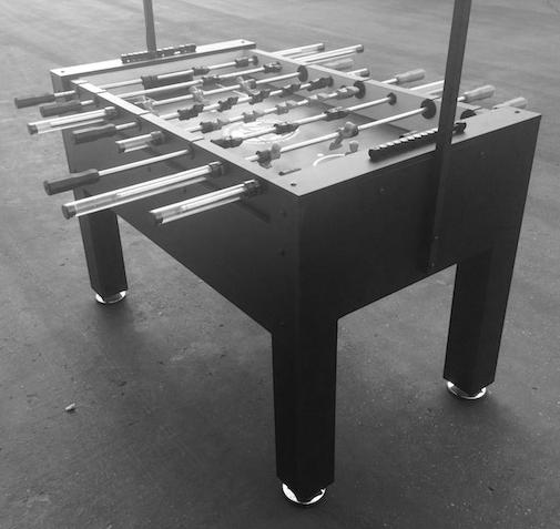
5 Table Assembly Instructions Note: No additional tools required for assembly. Nuts are pre-installed in the table. It is recommended to get all bolts Started only. After bolts have been started check alignment of top plates, leg panels & side panels before tightening bolts completely. No Impact/Power tools. 1. Attach Leg Leveler to legs by twisting in clockwise direction until they are all the way in.( do not over-tighten) then stand both legs in upright position. 2. Position both side panels (2) on each side of the leg panels (make sure the 5 pre-drilled holes are on the top ), using (8) 5/16 x 1-3/4 bolts with washers attach side panels to leg panels (Do not tighten yet) 3. Attach goal boxes (2), using (4) 1/4 x 1-3/4 bolts and washers. 4. Insert metal plate into precut slots in goal box. 5. Attach ball catch (1) using (2) 1/4 x 1-3/4 bolts with washers. 6. Install ball return runners (2) a. Attach White PVC Collar to box and slide Ball Return Tube on to white collar b. Make sure runner completely covers the collar c. Install White PVC Collars into ball catch d. Slide Ball Return Tube runner completely over ball catch collars 7. Place table top onto cabinet and secure using (6) 5/16 x 1-3/4 bolts with washers. (Do not tighten yet) 8. Loosely attach corners blocks (4) to side of table using (4) 1/4 x 1-3/4 bolts with washers (Align all side panels to legs and tighten all bolts securely.) 9. Attach top plate (2) using (4) 1/4 x 1-3/4 bolts. 10. Attach score beads (2) on to top plate using (4) #10 x 1-1/2 bolts. 11. Guide handle through opening in near wall in proper position. Pull all the way in to allow other end of rod to clear far wall. 12. Take 2 bearing halves (marked #1 and #2) and connect them over rod on both sides and then place them into wall by aligning tabs with openings in the side of wall opening. 13. On handle side install bearing nut and tighten fully 14. On rod exit side install Rod Guard Bearing and tighten fully 15. Repeat for remaining rods ROD and Guard Locations (view picture on cover for refrence) 1 man goalie rods use 10" rod guard and are closest to goal 2 man rods use 15" rod guard and are second rod from goal 5 man rods use 5" rod guard and are in the middle position of table 3 man rods use 10" rod guards and are furthest from goal Wipe down all rods and place one or two drops of silicone on each side near bearing rotate and slide rod into bearing to distribute silicone inside bearing Adjust leg levelers by rotating clockwise to raise and counter clockwise to lower 5 Page


6 Assembly Pictures 1. Install Leg Leveler by turning clockwise into bottom of legs. Turn all the way into the lowest point in leg. 2. Leg Panels w/ 1 Side Panel 3. Attach Goal Box and collar 4. Insert Metal Plate 5. Attach Ball Catch 6a install ball return runner to goal box collar 6 Page


7 Assembly Pictures 6b Install runner completely over collar 6c Install collars into ball catch 6d Install runner completely over collars 7. Place tabletop into cabinet 8. Install Corner Block with black finished sides exposed as shown 9. Attach Top Plate 7 Page


8 Assembly Pictures 10. Attach Score Beads to Top Plate 11.Guide handle through opening in near wall in proper position. Pull all the way in to allow other end of rod to clear far wall. 12.Take 2 bearing halves (#1 and #2) and connect them over rod and then place them into wall by aligning tabs with openings in the side of wall opening. 13.Slide bearing nut over handle & tighten 14.On rod side install Rod Guard Bearing and tighten fully Wipe rods down with cloth or napkin then add 1 or 2 drops of silicone Level table by turning leg levelers to raise or lower legs as needed 8 Page
9 Notes: 9 Page
SOCCER TABLE. Assembly Instructions
 Updated: 9/30/2015 SOCCER TABLE Assembly Instructions Table of Contents Parts Identifier... 3 Hardware Identifier. 4 Table Assembly Instructions... 5 Table Assembly Pictures..... 6, 7, 8 2 Page Parts Identifier
This manual will aid in the assembly of the FireBall V90 and FireBall X90. The assembly of both machines will be identical, unless specified.
 This manual will aid in the assembly of the FireBall V90 and FireBall X90. The assembly of both machines will be identical, unless specified. Step #1 Lay all parts out to verify quantities. (2) 2 x 25-1/4
O-Sullivan King 4 Poster Bed O-Sullivan Queen 4 Poster Bed Parts and Hardware List
 Parts and Hardware List A. Left Headboard Post 1 pc B. Right Headboard Post 1 pc C. Left Footboard Post 1 pc D. Right Footboard Post 1 pc E. Headboard Panel 1 pc F. Footboard Rail 1 pc. Spindles 4 pcs
Kai Installation Instructions
 Kai Installation Instructions Before Beginning Installation Read through the entire instruction thoroughly A minimum of 2 people are required for this assembly These instructions reflect typical assemblies;
GlideRite Retractable Cover System For Hot Spot Spas (SE & SLX only)
") List of Contents Quantity Description 12 #10 x 1 ½ Flat Head Phillips Screw (see pg. 2) 2 #10 x ½ Pan Head Phillips Screw (see pg. 2) 8 ¼ x 2 ½ Lag Bolt (see pg. 2) 7 ¼ 20 x 5 / 8 Hex Head Bolt (see pg.
List of Contents Quantity Description 12 #10 x 1 ½ Flat Head Phillips Screw (see pg. 2) 2 #10 x ½ Pan Head Phillips Screw (see pg. 2) 8 ¼ x 2 ½ Lag Bolt (see pg. 2) 7 ¼ 20 x 5 / 8 Hex Head Bolt (see pg.
#916 CLASSIC 16 GUN CABINET ASSEMBLY INSTRUCTIONS
 Thank you for purchasing this quality product. A list of PARTS and INSTRUCTIONS is included to assist you. Unpack and identify all parts included on the Parts List and Hardware List. If parts are missing,
GlideRite Retractable Cover System For HotSpring & Tiger River Spas (except Classic & pre-2000 Landmark Spas)
") List of Contents Quantity Description 12 #10 x 1 ½ Flat Head Phillips Screw (see pg. 2) 2 #10 x ½ Pan Head Phillips Screw (see pg. 2) 8 ¼ x 2 ½ Lag Bolt (see pg. 2) 7 ¼ 20 x 5 / 8 Hex Head Bolt (see pg.
List of Contents Quantity Description 12 #10 x 1 ½ Flat Head Phillips Screw (see pg. 2) 2 #10 x ½ Pan Head Phillips Screw (see pg. 2) 8 ¼ x 2 ½ Lag Bolt (see pg. 2) 7 ¼ 20 x 5 / 8 Hex Head Bolt (see pg.
Queen Wingback Bed King Wingback Bed
 Parts and Hardware List A. Side Rails with Attachment Hooks 2 pcs B. Foot Rail 1 pc C. Head Rail 1 pc D. Center Support Slat 1 pc E. Leg Supports 3 pcs F. Support Slats 4 pcs G. Flat Washers 8 pcs H. Lock
K-Emily Twin Nkl Canopy Bed K-Emily Twin Pink Canopy Bed K-Emily Purple Twin Canopy Bed
 Parts and Hardware List A. Headboard 1 pc B. Footboard 1 pc C. Side Rails 2 pcs D. Support Slats 3 pcs E. Leg Supports 3 pcs F. Long Canopy Rails 2 pcs G. Short Canopy Rails 2 pcs H. Long Posts 2 pcs I.
Series 4 HV Single Monitor Lift Assembly Instructions
 6703 Zinser Street Schofield, WI 54476 6/13/17 Series 4 HV Single Monitor Lift Assembly Instructions Read all the instructions before beginning. Hardware Pack # 53368 Page1 OF 6 Tools Required for Assembly:
400A 40113V, 401A 40120V, & 401AL 40120VL ALUMINUM VERTICAL 4000 LB LIFT INCLUDES SCREW LEG ASSEMBLY INSTRUCTIONS
 12/11/07 PAGE 1 OF 12 400A 40113V, 401A 40120V, & 401AL 40120VL ALUMINUM VERTICAL 4000 LB LIFT INCLUDES SCREW LEG ASSEMBLY INSTRUCTIONS Thank you for purchasing our product! *Please read these instructions
 INSTRUCTION BOOKLET #C10 Watch step by step installation instructions at: https://www.wallbedsbywilding.com/wallbed-installation-studio-series/ WARNING! ALL MURPHY/WALLBED SYSTEMS CONTAIN STORED ENERGY.
https://www.wallbedsbywilding.com/wallbed-installation-studio-series/
 For Wallbed models: KING SIZE INSTRUCTION BOOKLET #C1 Watch step by step installation instructions at: https://www.wallbedsbywilding.com/wallbed-installation-studio-series/ WARNING! ALL MURPHY/WALLBED
27693 Trend Podium Desk
 1 27693 Trend Podium Desk Assembly Instructions #27693 Trend Podium Desk Hardware List Part Drawing Description Qty P-1 Table Top 1 EA Part Drawing Description Qty A Screw M6 X 15mm 13 EA B Screw M6 X
 For Wallbed models: KING SIZE INSTRUCTION BOOKLET #C1 Watch step by step installation instructions at: https://www.wallbedsbywilding.com/wallbed-installation-studio-series/ WARNING! ALL MURPHY/WALLBED
Side Mount INSTRUCTION BOOKLET #C122 BED STYLE: PARK CITY
 Side Mount BED STYLE: PARK CITY INSTRUCTION BOOKLET #C1 WARNING! ALL MURPHY/WALLBED SYSTEMS CONTAIN STORED ENERGY. FAILURE TO USE AND FOLLOW THESE INSTRUCTIONS DURING THE INSTALLATION PROCESS COULD RESULT
3 D Printer Enclosure Assembly Instructions
 3 D Printer Enclosure Assembly Instructions Tools Required: 2.5 mm Allen wrench (included) Phillips screwdriver Adjustable Wrench Parts Included: Plexiglas Back with fan and filters installed (29.5 x 35.5
Jenny Legs Assembly Instructions
 Jenny Legs Assembly Instructions R EXTENDED PHILLIPS BIT MM ALLEN WRENCH 6MM HEX DRIVE /" 007 Steelcase Inc. Grand Rapids, MI 90 U.S.A. Printed in U.S.A. Page of 6 88000 Rev F Jenny Club Instructions:
INSTRUCTION BOOKLET #C20
 INSTRUCTION BOOKLET #C0 WARNING! ALL MURPHY/WALLBED SYSTEMS CONTAIN STORED ENERGY. FAILURE TO USE AND FOLLOW THESE INSTRUCTIONS DURING THE INSTALLATION PROCESS COULD RESULT IN SEVERE PERSONAL INJURY TO
Models 2230 and 2240
 Models 2230 and 2240 Overview... 2 Tools Needed... 2 Hardware...3 Assembly... 4-13 Installation... 14 Drawer Removal... 15 Operation... 15 Maintenance... 15 Accessories... 16 Limited Warranty... 16 Perform
AndyMark DART 12.
 AndyMark DART 12 Part Number Description QTY These Parts Are Pre-Assembled by AndyMark am-0031 Bearing, 3/16"ID (R3) 1 am-0209 Bearing, 3/8"ID 1614ZZ 2 am-1028 Screw, #10-32x3/8 Pan Head Philips 8 am-1121
INSTRUCTION BOOKLET #C21. For Wallbed models: KING SIZE
 For Wallbed models: KING SIZE INSTRUCTION BOOKLET #C1 WARNING! ALL MURPHY/WALLBED SYSTEMS CONTAIN STORED ENERGY. FAILURE TO USE AND FOLLOW THESE INSTRUCTIONS DURING THE INSTALLATION PROCESS COULD RESULT
Footprint Mobile Assembly Instructions
 Footprint Mobile Assembly Instructions 1998754 Revision -1 Complete Series Master Packet If you have any questions concerning these instructions, please call Kimball Office Customer Service. 20 Kimball
4-Piece Table Tennis Table
 Item# 45-6074 4-Piece Table Tennis Table Please keep this instruction manual for future reference If you have any problems with your new product, please contact Triumph Sports USA at 1-866-815-4173, or
 INSTRUCTION BOOKLET #C0 Watch step by step installation instructions at: https://www.wallbedsbywilding.com/wallbed-installation-studio-series/ WARNING! ALL MURPHY/WALLBED SYSTEMS CONTAIN STORED ENERGY.
SatNOGS. SatNOGS Rotator v3 Mechanical Assembly. This is the assembly guide for the third version of the SatNOGS Rotator.
 SatNOGS SatNOGS Rotator v3 Mechanical Assembly This is the assembly guide for the third version of the SatNOGS Rotator. Written By: Pierros Papadeas 2017 satnogs.dozuki.com Page 1 of 19 INTRODUCTION Notes:
ASSEMBLY INSTRUCTIONS RIGHT & LEFT HAND "J" TABLE
 ASSEMBLY INSTRUCTIONS RIGHT & LEFT HAND "J" TABLE (1) COMPONENT LIST FOR RIGHT & LEFT HAND "J" TABLE NOTE: Please count and inspect all pieces before disposing of any carton or packing materials. 24" x
BELGIAN EXT. REC DINING TABLE
 BELGIAN EXT. REC DINING TABLE Date: Williams 20 Jul. 2015 Sonoma Product Information Dept. www.williams sonoma.com Page 1 of 5 Page 1 of 5 Important Safety Instructions: Please read all instructions carefully
P a r k c o n s o l e s i n k a s s e m b l y i n s t r u c t i o n s
 P a r k c o n s o l e s i n k a s s e m b l y i n s t r u c t i o n s Before You Begin: Professional installation by two-person crew is required for this fixture. Install water supply and drain piping
This instruction manual is an in-depth look and explanation of how to assemble and install the Murphy Bed properly and efficiently.
 This instruction manual is an in-depth look and explanation of how to assemble and install the Murphy Bed properly and efficiently. Don t be put off by the size of the instruction manual as the large diagrams
INSTRUCTION BOOKLET #34. For Wallbed models: KING SIZE SIERRA WITH STORAGE HEADBOARD
 For Wallbed models: KING SIZE SIERRA WITH STORAGE HEADBOARD INSTRUCTION BOOKLET #34 WARNING! ALL MURPHY/WALLBED SYSTEMS CONTAIN STORED ENERGY. FAILURE TO USE AND FOLLOW THESE INSTRUCTIONS DURING THE INSTALLATION
v1.0 ASSEMBLY GUIDE Mia Wide Bookcase
 v1.0 ASSEMBLY GUIDE Mia Wide Bookcase Components Upon unpacking your bookcase from it s delivery box, you should have the pieces shown. Follow the steps on the next pages to assemble your new bookcase.
XHD Bull Bar w/ Dual Row LED Light Bar (10-17 Jeep JK)
") XHD Bull Bar w/ Dual Row LED Light Bar (10-17 Jeep JK) PARTS LIST: 1 Driver/Left Side Bull Bar Upright 8 10-1.5mm Hex Nuts 1 Side Bull Bar Upright 4 10-1.5mm Nylon Lock Nuts 1 Top Cross Bar 2 Light Bar
XHD Bull Bar w/ Dual Row LED Light Bar (10-17 Jeep JK) PARTS LIST: 1 Driver/Left Side Bull Bar Upright 8 10-1.5mm Hex Nuts 1 Side Bull Bar Upright 4 10-1.5mm Nylon Lock Nuts 1 Top Cross Bar 2 Light Bar
Steel Frame Assembly
 Steel Frame Assembly The Alpha Steel Frame is adaptable as vertical or horizontal bed. Note: A leg connector rod extension bar is required for a horizontal bed. Hardware Card #3 is used for Steel Frame
Sit Down Table Assembly Instructions
 Sit Down Table Assembly Instructions Parts that come with your sit down table A B C D E F G H I J K L M N Extension leaf Table with cutout for machine Two table legs One table leg with long support One
BF12-SERIES Flash Stands
 BF12-SERIES Flash Stands Document # 16-462 Assembly and Operating Instructions Please review all these instructions prior to assembly. The BF12-SERIES stands come in two models, standard duty and heavy
RBP-1215B-RX DODGE RAM QUAD CAB RX3
 RBP-1215B-RX3 2002-2017 DODGE RAM 15-3500 QUAD CAB RX3 Passenger side RX-3 Side Step Drill Template Passenger side rear Modular Bracket (6) L Support Brackets Driver side rear Modular Bracket Driver side
IDR assembly instructions:
 IDR assembly instructions: Required Tools: 2 X 12mm Open End Wrench 14mm open end wrench #2 Phillips Head Screw Driver (Drill with adjustable torque clutch recommended) 8mm nut driver (Supplied in IDR-AK)
200A FLB VERTICAL 22113V LIFT W/CHAIN DRIVE WINCH
 PG. 1 OF 11 PORTA-DOCK, INC. 200A FLB VERTICAL 22113V LIFT W/CHAIN DRIVE WINCH STEP 1. Separate and group like parts and fasteners together. Locate the winch side member with the longer upright tube and
INSTALLATION INSTRUCTIONS
 NOTE: Bolts should remain hand tight until all bolts are installed. STEP 1 Installing the door base (both sides). 1. Locate the outer, roll cage, mounting bolt (passenger side is shown in the illustration).
ABM International, Inc. Navigator Assembly Manual
 ABM International, Inc. 1 1.0: Parts List Tablet (Qty. 1) Tablet mount (Qty. 1) NOTE: Mount may appear and operate different then image below Control Box (Qty. 1) Motor Power Supply (Qty. 1) 2 X-axis motor
The Bowflex Revolution XP Home Gym Assembly Instructions. P/N: Rev ( /0 )
") P/N: 001-7057 Rev ( /0 ) The Bowflex Revolution XP Home Gym Assembly Instructions 2 Table of Contents Before You Start... 2 Tools You Will Need / Hardware Contents... 3 Box Contents... 6 Assembling Your
P/N: 001-7057 Rev ( /0 ) The Bowflex Revolution XP Home Gym Assembly Instructions 2 Table of Contents Before You Start... 2 Tools You Will Need / Hardware Contents... 3 Box Contents... 6 Assembling Your
Motorized or Crank Operated Fortress Zipper Track Shade with Housing and Side Track Installation Instructions
 Motorized or Crank Operated Fortress Zipper Track Shade with Housing and Side Track Installation Instructions Tools Needed Drill 3/8 Metal Drill Bit ¼ Masonry Drill Bit Measuring Tape Pencil 4 Level Phillips
AUTOMATIC ADVANCE MANUAL
 AUTOMATIC ADVANCE MANUAL AVL Looms, Inc. 3851 Morrow Lane, Suite #9 Chico, CA 95928-8305 530 893-4915 530 893-1372 fax # info@avlusa.com www.avlusa.com Copyright 2009 TABLE OF CONTENTS Page # I. Parts.........................
MODEL T28173/T28174 ROLLER TABLES INSTRUCTIONS
 MODEL T28173/T28174 ROLLER TABLES INSTRUCTIONS FOR MODELS MFD. SINCE 10/17 For questions or help with this product contact Tech Support at (570) 546-9663 or techsupport@grizzly.com Rails Rollers Reversible
INSTALLATION INSTRUCTIONS
 Do not attempt to install this product on any vehicle other than the one it is designed for and listed above! Parts List 10 3/8 X 1 1/4 Hex Bolt 10 3/8 Lock Washer 4 3/8 Hex Nut 4 3/8 Flat Washer 2 3169)
Assembly, Installation, Operation and Maintenance Instructions Kit, Base Rail Bracket Part # 31852
 . Assembly, Installation, Operation and Maintenance Instructions Kit, Base Rail Bracket Part # 31852 Dealer / Installer: Provide a copy of these instructions to the end user of this product. These instructions
08+ KAWASAKI KLR PD NERF
 08+ KAWASAKI KLR PD NERF 0505-1299 Before you begin, place the bike on a hard level surface where you have room to work. Lay out the parts included in this kit and compare to the parts list on page 5 of
Important Loading Information. Tools Required. Meridian Lateral Files Instructions
 Y Meridian Lateral Files Instructions! WARNING Failure to observe stated capacities below will result in unsafe usage conditions, causing possible product damage or personal injury. Important Loading Information
Assembly Instructions for model: VMPR1
 Assembly Instructions for model: VMPR1 Congratulations on your purchase! The VMPR1 ceiling mount provides a unique, simplified method of ceiling mounting inverted LCD/DLP projectors. Its low profile design
SS1062, SS10621 & SS10621E Free Standing PWC & Fishing Boat Hoist SS1062 SS10621 SS10621E
 SS1062, SS10621 & SS10621E Free Standing PWC & Fishing Boat Hoist SS1062 SS10621 SS10621E Midwest Industries, Inc. Page 1 Ida Grove, IA 51445 800.859.3028 www.shorestation.com 0003231 REV A 1/25/05 Bundles
Pack Mount Instructions:
 Pack Mount Instructions: STEP 1 Mounting upright base to desired surface If mounting to a surface with an accessible backside (such as a thin walled container): Option 1 Discard the Round Mounting Disk
Medium HoneyBadger Chase Rack Installation Instructions
 PREPARATION Medium HoneyBadger Chase Rack Installation Instructions 1. Disconnect the negative terminal on the battery. Park the vehicle on level ground and set the emergency brake. 2. We recommend reading
INSTALLATION INSTRUCTIONS
 INSTALLATION INSTRUCTIONS For Wallbed models: Do-It-Yourself BOOKLET #C90 WARNING! ALL MURPY/WALLBED SYSTEMS CONTAIN STORED ENERGY. FAILURE TO USE AND FOLLOW THESE INSTRUCTIONS DURING THE INSTALLATION
Signature Choral Riser Side Rail
 Assembly/Owner s Manual Signature Choral Riser Side Rail Signature Choral 3-Step Riser with Optional Side Rail Signature Choral 4-Step Riser with Optional Side Rail CONTENTS Visit the Signature Choral
Gared Pro-S Portable Backstop
 Models: 9616 & 9618 Installation, Operation and Maintenance Instructions Please read all instructions before attempting installation or operation of these units SAVE THESE INSTRUCTIONS FOR FUTURE USE PUBLICATION
Product Instruction Booklet
 Product Instruction Booklet Contents: Page No. Pack Mount: This the set up that most people start with. 1 CARB Spout: Designed to reduce the chance of spilling as well as reducing the emissions of harmful
Step 1: The larger tower box contains the tower machine, a set of Silver 100 Lid Keys, and a set of Black 002 Coin Box Keys
 2 3 Step 1: Each tower is shipped as two boxes the large tower box and the smaller stand box. Open each of the boxes and inventory each of the parts before starting assembly to ensure all parts have arrived.
Assembly Instructions Nevins Phone Booth
 Assembly Instructions Nevins Phone Booth Included Hardware Tools Required supplied by installer Drill & Bit Bolt A - (16) 1/4-20 x 1-1/2 hex head Bolt B - (20) 1/4-20 x 2-1/2 phillips head Screw 1 - (24)
BIFOLD FUTON FRAME TRINITY ARM. Seat Rails and Slats x 1. *Note: Use 4pc of 100mm Bolts and 4pc of 60mm Bolts to attach the arms to the Stretchers.
 1A Parts in this box. 2pc with extra holes 2pc with extra holes & plastic stoppers Arms x 2 Back Rails and Slats x 1 Full Size: Slat Supports x 6 3pc are longer for the Back deck Back Side Rails x 2 Seat
Assembly Instructions. Important!
 Play Action Spiral Tube Slide Assembly Instructions Important! Intended for residential use by children ages 2 to 10, only on properly installed PlayStar playsets. Before use refer to complete safety guidelines
Calf-Tel Pen System Assembly Instructions
 Calf-Tel Pen System Assembly Instructions (Instructions work for 4, 6, and the 7 Pen Systems) 1 ASSEMBLY OF PEN FRONT AND WALLS START THE ASSEMBLY BY LINING UP THE TWO UNI-DIRECTIONAL ARROWS IN THE TOP,
TOOLS REQUIRED FOR ASSEMBLY. Rubber Mallet or Plastic Tip Hammer PARTS REQUIRED FOR ASSEMBLY OF SINGLE ENTRY STARTER.
 TOOLS REQUIRED FOR ASSEMBLY Rubber Mallet or Plastic Tip Hammer Top Cover Support PARTS REQUIRED FOR ASSEMBLY OF SINGLE ENTRY STARTER Back Stop Divider Closed 'L' Upright Slotted Reinforcement Support
Model 209 Fireback Replacement
 Model 209 Fireback Replacement Please read all the instructions before you begin the procedure. Confirm that you have all the necessary tools and materials. If you have any questions, technical support
User Instructions Multiline Otter Scoreboard Caddy Assembly
 List of parts: User Instructions Multiline Otter Scoreboard Caddy Assembly Single Caddy Double Caddy 1 1 Base assembly with attached wheels 2 4 1 1 2 4 4 8 10 20 12 Uprights (60 or 74 aluminum extrusion)
ASSEMBLY INSTRUCTIONS MANUAL
 PAGE 1 OF 9 RECOMMENDED TOOLS FOR ASSEMBLY: ALLEN WRENCH (INCLUDED) BOX WRENCH (INCLUDED) PHILLIPS SCREW DRIVER (NOT INCLUDED) PARTS IN CARTON: ALLEN WRENCH SCREWS (20 EACH) ROUND HEAD SCREWS (8 EACH)
Assembly Instructions
 Laminate/Phenolic & 1 Pc Butcherblock Tops Before you begin, please make sure all parts and proper quantities are included. (See on next page) Any parts damaged during shipment must be reported within
Exponents Bench Cushion
 Exponents Bench Cushion Power Drill #2 Phillips Bit Bit Holder Page 1 of 2 939500640 Rev A 1. Place cushion on top of the bench, so the black Coalesse tag is in the right rear corner of the bench. 2. From
7878 K940. Checkpoint Antenna. Kit Instructions. Issue B
 7878 K940 Checkpoint Antenna Kit Instructions Issue B Revision Record Issue Date Remarks A July 7, 2009 First issue B Nov2013 Revised the Checkpoint installation procedures for 7878 and 7874 scanners Added
Modular Teacher s Desk Systems
 Modular Teacher s Desk Systems ssembly Instructions 1 Modular Teacher s Desk Components Part Drawing Description Qty Part Drawing Description Qty 90390 djustable Leg-1S 90369 Modular Pedestal 90391 djustable
WOLF LOOM DOUBLE BACK BEAM
 WOLF LOOM DOUBLE BACK BEAM Assembly Instructions Find out more at schachtspindle.com Schacht Spindle Company 6101 Ben Place Boulder, CO 80301 p. 303.442.3212 f. 303.447.9273 2017 Schacht Spindle Company,
Sentinel Series Cigar Humidor End Tables
 Sentinel Series Cigar Humidor End Tables Assembly Instructions Models: Sentinel 500, 1000 and 1500 Style: Contemporary SENTINEL ASSEMBLY INSTRUCTIONS Congratulations! You have purchased a superior cigar
Installation and Assembly: Flat Video Wall Mount For 40" to 65" Flat Panel Displays
 Installation and Assembly: Flat Video Wall Mount For 40" to 65" Flat Panel Displays Model: DS-VW665 Maximum Load Capacity: 125 lb (57 kg) 1 of 11 ISSUED: 03-22-12 SHEET #: 125-9288-4 06-25-13 NOTE: Read
Assembly Instructions
 1 27694 Trend Podium Assembly Instructions #27694 Trend Podium Part Drawing Description Qty Part Drawing Description Qty P-1 Base 1 EA Hardware List Screw M6x12mm 30 EA P-2 Right Side Panel 1 EA A2 Phil
Coro Character PVC Frame Instructions:
 Coro Character PVC Frame Instructions: In this tutorial we will show you how to make a basic light weight frame for your Coro character. Then we will show you how to add on to your frame to help you either
AX1001. Smith/Functional training Combo-free weight ASSEMBLY INSTRUCTIONS
 AX1001 Smith/Functional training Combo-free weight ASSEMBLY INSTRUCTIONS EXPLODED DIAGRAM 83 84 84 85/86 87 87 88 89 90 91 62 64 64 64 64 64 64 65 65 65 65 66 66 65 66 66 65 63 63 66 67 68 55 66 66 70
IN 578. Tools Required. Torque Specification: 10mm Socket 7/16 Socket 1/2 Socket 1/2 Wrench 7/16 Wrench 1/8 Allen Wrench.
 Tools Required 2011-C Ford F250/F350 No Drilling into Vehicle is Required 10mm Socket 7/16 Socket 1/2 Socket 1/2 Wrench 7/16 Wrench 1/8 Allen Wrench FL277 x 1 Torque Specification: 1/4 Bolts - 6 Ft Lbs.
Shetland Stalls Installation Instructions
 Shetland Stalls Installation Instructions RAMM Horse Fencing and Stalls 13150 Airport Hwy. Swanton, OH 43558-9615 1-800-434-8456 Rev. 1/9/18 Before you start Kit can accommodate up to 12 wide stall front
INSTALLATION INSTRUCTIONS
 INSTALLATION INSTRUCTIONS Trans4mer Grille Guard/Winch Mount Kit 645 For Chevrolet Silverado 500HD & 3500 This WARN Trans4mer system can be customized to give your Chevy Silverado a wide variety of looks,
INSTALLATION INSTRUCTIONS DODGE RAM 2 & 4WD 1500 PART # P5058
 INSTALLATION INSTRUCTIONS 2009-13 DODGE RAM 2 & 4WD 1500 PART # P5058 PARTS LIST: Qty Description Qty Description 1 Grille Guard 12 12-1.75mm Hex Nuts 2 Upper Frame Mounting s (for trucks without tow hooks
ASSEMBLY AND ADJUSTMENT
 EDGE MONITOR ARM EDGE Rev A 2/17 Model EDGE-SLV Model EDGE-BLK Model EDGE-WHT ASSEMBLY AND ADJUSTMENT EDGE MONITOR ARM PARTS AND TOOLS PLEASE REVIEW these instructions before beginning the assembly and
PAK Drum Roll Top Assembly Instructions. Note: 2 people will be required to assemble roll top
 PAK901 4 Drum Roll Top Assembly Instructions Note: 2 people will be required to assemble roll top PLEASE READ ASSEMBLY INSTRUCTIONS CARFULLY Tools required: 5/8 Socket & Ratchet 9/16 Deep Well Socket &
WK9 WORKTOP KIT Assembly Guide
 WK9 WORKTOP KIT Assembly Guide Tools and supplies needed for assembly: Cordless drill with #2 Phillips bit 5/16" drill bit #2 Phillips screwdriver Bubble level Sharp felt tip marker 3/8" and 7/16" wrenches
INSTALLATION INSTRUCTIONS GRILLE GUARD RAM 1500 PART # 5058/5058-2
 INSTALLATION INSTRUCTIONS GRILLE GUARD PART # 5058/5058-2 PARTS LIST: Qty Description Qty Description 1 Grille Guard 8 12-1.75mm x 35mm Hex Bolts 2 Upper Frame Mounting s (for trucks without tow hooks
Thanks for shopping with Improvements! Mandarin Tansu Step Cabinet Item #512735
 Thanks for shopping with Improvements! Mandarin Tansu Step Cabinet Item #512735 This unit can be assembled so the top and middle cabinets are on the left or on the right. Use these instructions for a right-sided
Topo Freestanding Applications - Private Office
 4 3 2 Topo Freestanding Applications - Private Office Combo Wrench If you have a problem, question, or request, call your local dealer, or Coalesse at 1.800.627.6770 Or visit our website: www.coalesse.com
The Portable Open Source 3D Printer
 http://web.archive.org/web/201502142011/http://www.tantillus.org/build_3.html Page 1 of 12 captures 12 Oct 12 - Feb 15 The Portable Open Source 3D Printer Home Start Case X/Y Axis Extruder Z Axis Electronics
Installing flat panels on the MPL15 wall mount
 Installing flat panels on the MPL15 wall mount The MPL15 (DS-VW775) is a full-service video wall mount that can accommodate tiled LCD panels with up to a 400 x 400 mm VESA pattern in portrait and landscape
Chain Drive Vise. Installation Instructions. (revised 05/04/2016)
") Chain Drive Vise Installation Instructions (revised 05/04/2016) Lie-Nielsen Chain Drive Vise Instructions Table of Contents page About Your Chain Drive Vise 3 Parts List 4 Exploded Parts Diagram 5 step
Chain Drive Vise Installation Instructions (revised 05/04/2016) Lie-Nielsen Chain Drive Vise Instructions Table of Contents page About Your Chain Drive Vise 3 Parts List 4 Exploded Parts Diagram 5 step
Riverside. Windhaven Queen Storage Bed Assembly Instructions
 Queen Storage Bed Page 1 of 7 2 pcs. 4 pcs. 4 pcs. 4 pcs. 2 pcs. 5/0 Queen Storage Bed 50773 -- 5/0 Storage Footboard w/platform Note: The 50773 Storage Footboard can be used with the 50770 Panel Headboard
Sentinel Series Cigar Humidor End Tables
 Sentinel Series Cigar Humidor End Tables Assembly Instructions Models: Sentinel 500, 1000 and 1500 Style: Traditional SENTINEL ASSEMBLY INSTRUCTIONS Congratulations! You have purchased a superior cigar
Riverside. Harbor Hill Queen Storage Bed Assembly Instructions
 Queen Storage Bed Page 1 of 7 8 pcs. 8 pcs. 1 pc. 2 pcs. 3 pcs. 3 pcs. 4 pcs. 4 pcs. 4 pcs. 1 pc. 1 pc. 8 pcs. 8 pcs. 8 pcs. 2 pcs. 8 pcs. 1 pc. 25770 -- 4/6-5/0 Panel Headboard (NOTE: the 25775 Leather
MISSION AUDIO STAND GBU
 MISSION AUDIO STAND Thank you for purchasing our Mission Audio Stand. Assembly of this product requires a Phillips screwdriver and a hammer. We have found it helpful to have a second person present in
Cabinet Mount Lifter Instructions
 PART LIST 2 @ Side Pivot Arms 1 @ Coupler Tube 1 @ Left Hand Bracket 1 @ Right Hand Bracket 2 @ Cover Support Arms w/ Foam Grip 1 set of Cover Saver 4 @ 4 Wood Screw 8 @ 1 Wood Screw 12 @ 1 Black Tek Screw
RH-412 STEEL DOORS INSTALLATION INSTRUCTIONS
 RH-412 STEEL DOORS INSTALLATION INSTRUCTIONS By following the steps outlined below, the assembly, installation and adjustment of the steel doors, will be a simple process. Let s start with the Driver Side.
Assembling Insert NO. ITEM DESCRIPTION QTY. CALLUM 6-DRAWER TWIN/FULL STORAGE CANOPY BED. Long Bolt 5/16 x 2-1/4 20 pcs. 20 pcs.
 CALLUM 6-RAWER TWIN/FULL STORAGE CANOPY BE PARTS INCLUE: A [1] HEABOAR PANEL B [2] HEABOAR POSTS C [2] FOOTBOAR POSTS [2] SIE RAWER FRAME E [2] SHORT SIE RAILS F [2] STORAGE BASE G [1] SLAT ROLL H [8]
WILDING WALLBEDS INSTALLATION INSTRUCTION Side Mount
 WILDING WALLBEDS INSTALLATION INSTRUCTION Side Mount For Wallbed models: Do-It-Yourself Insturction booklet C92 WARNING! ALL MURPHY/WALLBED SYSTEMS CONTAIN STORED ENERGY. FAILURE TO USE AND FOLLOW THESE
INS T A L L A TIO N INS T R U C TIO N S. Ceiling Mount Track System
 Ceiling Mount Track System 10.26.2016 Specifications Ceiling Post: Unassembled 2-7/8 Assembled 1-11/16 7/8 7-9/16 5-7/8 3/8 2 Tubes 1/2 2-3/8 5 Parts and Tools Tools Needed Tape Measure Pencil Drill with
3000 SERIES STEPGUARD
 3000 SERIES STEPGUARD GRILLE GUARD ASSEMBLY INSTRUCTIONS PART NO. 3295B & 3295C 2015 FORD F-150 Do not attempt to install this product on any vehicle other than the one it is designed for and listed above!
Required Tools: Suggested Additional Tools: 1 Cordless Drill with Robertson Bits 1 Ratchet Wrench 1 7/16 or 11mm socket 1 7/16 or 11mm Gear Wrench
 Thank you for your recent purchase of a Cabinets by Hayley garage cabinet system. You are about to experience the best made cabinets that you can purchase. Cabinets by Hayley are designed for beauty and