How to Build the Robotics++ V2 Robot. Last Edited Nov
|
|
|
- Shanna Clarke
- 6 years ago
- Views:
Transcription


1 How to Build the Robotics++ V2 Robot Last Edited Nov


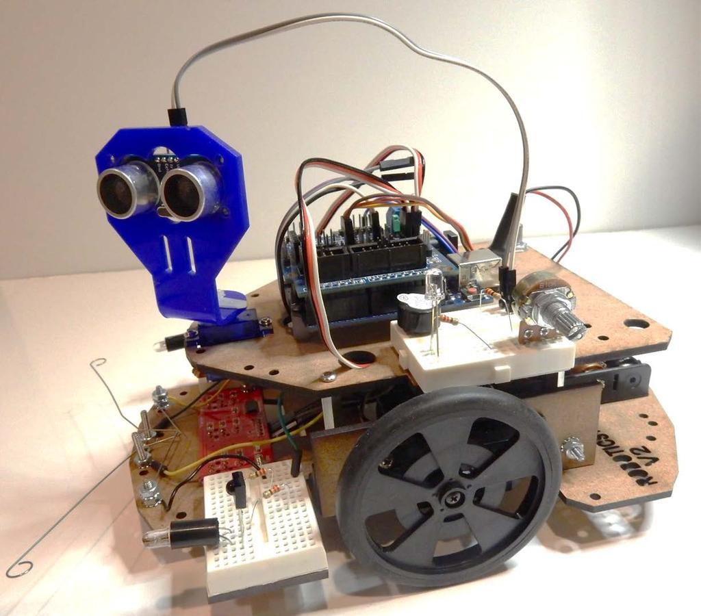
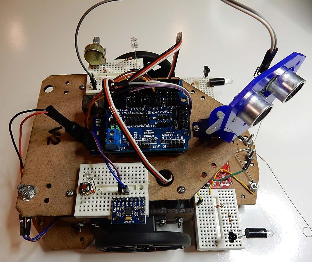
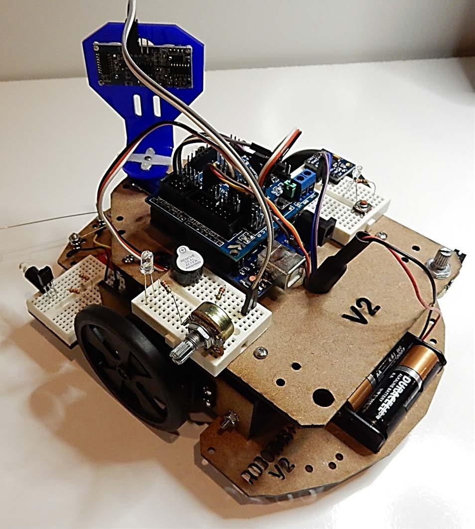
2 Completed Robotics++ V2 Robot. More views of completed robot can be found at the end of this instructions manual The fun starts now! 2

3 Parts included in the V2 Kit 3
 servo holders Note: You may also refer to the pictorial parts list to learn more about each component")
4 Step 1: Assembling the Motors Parts: (2) Servo Motors (12) ½ inch screws (12) 4-40 lock nuts screwdriver (4) plastic servo holder brackets (2) servo holders Note: You may also refer to the pictorial parts list to learn more about each component 4


5 Insert the servo motors into the servo holders and secure them with the screws and nuts as shown on the right photo. Please Note: - how the motors are inserted into the servo holders - how the screws face in on the servo holders - how the shaft of the motor is on the front on both left and right sides. - bottom holes on the servo holders must stay on the bottom to mount the plastic servo brackets Hole for shaft servo bracket 5


6 Notice how the position of the shaft on each sensor holder is on opposite ends 6
 4-40 nuts (2) ½ screws (2)plastic brackets")
7 Step 2: Assembling the plastic servo holder brackets Parts: (2) 4-40 nuts (2) ½ screws (2)plastic brackets 7


8 Paying attention to the direction that the screw goes, assemble the plastic brackets as shown below on both servo holders 8
4-40 locking nuts and ½ screws -")

9 Step 3: Assembling the Line Following Sensor Parts: - lower chassis - line following sensor - (2)4-40 locking nuts and ½ screws - screwdriver Insert line following sensor as shown below. Note: pay attention that the chassis is facing up and you can read Robotic++ FRONT 9


10 We will install the front plastic acorn nut first Using the ½ inch flat head screw and 4-40 lock nut proceed to install as shown below. Note: - Try to tighten the acorn nut as much as possible Parts: - ½ 4-40 flat head screw lock nut - plastic acorn nut 10

11 Step 4: Assembling the Feelers (switch) Sensor The feeler sensor are metal piece that is assembled so that when it touches the metal screws completes the circuit and can trigger a response. These are secondary sensors in case our other sensors do not work. Parts: - (2) ¾ inch flat head screws - (2) Dupont M/F wires - (2) jumper wires - (2) ½ screws - (6) lock nuts - (2) metal feelers - Screwdriver - Lower chassis 11
 flat heads go in the center")

12 Insert screws as shown. Note: - two larger screws (3/4) flat heads go in the center and the other two ½ screws go on the sides - Two larger Dupont M/Fwires go in the center and the two smaller jumpers go on the side held by the lock nuts 12


13 A Closer view of mounting of metal feelers, screws, nuts and wires. Metal feelers should not be touching the screws as shown. You might need to borrow some pliers from uncle Bob to tighten these nuts Make sure they feelers are not touching screw 13


14 Another view of the metal feelers installation 14

 metal spacers - (16) ½ inch")
15 Step 5: Assembling the servo motors on lower chassis Parts: - the two servo assemblies - lower chassis - (4) metal spacers - (16) ½ inch screws 15


16 Install servo assemblies as shown on the top side of the lower chassis using the metal spacers and the ½ inch screws. Note: don t make it too tight yet as you need to put the upper chassis and might require some adjustments Also, make sure servo shaft points to the front of chassis Servo shaft points to the front of the chassis 16


17 Step 6: Assembling the battery holder and back acorn nut balancer Parts: - Battery holder - ¾ inch flat head screw - Plastic acorn nut - Lower chassis lock nut - screwdriver ¾ inch flat head screw 17

18 Complete battery holder and plastic acorn 18
 plastic spacers - (10) ¼ inch screws - Arduino board -")

19 Step 7: Assembling the lower chassis and Arduino board Parts: - upper chassis - (3) plastic spacers - (10) ¼ inch screws - Arduino board - screwdriver Use the 3 plastic spacers and three ¼ inch screws and install the spacers on the Arduino board as shown below Install 3 plastic spacers 19


20 Completed assembly of Arduino board on top of upper chassis Note: - Arduino board can only go in one direction. The holes on the upper chassis match the direction that the Arduino board should go 20


21 Mount the upper chassis to the four metal spacers as show below using the ¼ inch screws. Also install the Arduino Sensor Shield as seen below. Note:- Pull the servo wires thru the holes as shown below for each side Install power switch as show here-> ¼ inch screws Arduino Sensor Shield v5.0 21


22 Step 8: Assembling the wheels Parts: - (2) wheels - (2) screws from servo motors parts bag to mount wheels - screwdriver Insert wheel carefully, but with force to the shaft of the servo motor. Use only the screws that come in the bag of servo horns. These will make sure to hold the wheels. Wheel screws comes in the servo bags of spare horns 22


23 completed chassis and wheels assembly 23

")
24 Step 9: Installing the Breadboards Peel off back from the double sided tape on the breadboards and install them as seen below Parts: - (4) breadboards 24

25 That s it! Now we can start the experiments to learn how to program the robot with creative algorithms, motor control, basic electronics and sensor interfacing. Please visit to download these exciting projects. Have FUN! 25
26 26
27 27
28 28
ORTOP Modular Robot v3.0 Arm Assembly
 Base Plate Assembly Parts Needed: Arm Assembly BAG 1 2 Socket Head Cap Screw, 1-1/4" 2 Socket Head Cap Screw, 1/2" 2 Button Head Cap Screw, 3/8" 6 Nuts 1 Gear Hub Spacer 1 Flat Building Plate 1 Single
Fabscan100 Assembly instructions v.1.00
 Fabscan100 Assembly instructions v.1.00 Figure 1: The Fabscan100. Content: List of material 2 Assembly group 1: Turning Table 3 Assembly group 2: Camera/Laser Bracket 8 Assembly group 3: Housing 12 Final
ESRA III. Expressive System for Robotic Animation
 ESRA III Expressive System for Robotic Animation 1 ESRA III Kit Contents 1 Hitec Servos 8 Upper Eye Support 2 Dagu (New as of 7/12) 9 Lower Eye Support 3 Eye Balls 10 Main Support 4 Flat Servo Plate 11
M2 Assembly. M2 Sub-Assemblies mm Belt Sub-Assembly mm Belt Sub-Assembly Spider Sub-Assembly... 4
 M2 Assembly Table of Contents M2 Sub-Assemblies... 3 630mm Belt Sub-Assembly... 3 702mm Belt Sub-Assembly... 3 Spider Sub-Assembly... 4 Idler Bolt Sub-Assembly... 8 Y Motor Sub-Assembly... 9 X Motor Sub-Assembly...
Budget Robotics Octabot Assembly Instructions
 Budget Robotics Octabot Assembly Instructions The Budget Robotics Octabot kit is a low-cost 7" diameter servo-driven robot base, ready for expansion. Assembly is simple, and takes less than 15 minutes.
Super Sky Surfer 2000 Assembly Instructions
 Super Sky Surfer 2000 Assembly Instructions Note: Plug and Play version of the Sky Surfer comes with fuselage pre-glued and motor/servos installed. If you wish to route antennas or wires through the tail,
ZROADZ Grille series - LED Installation Guide
 ZROADZ Grille series - LED Installation Guide START HERE The ZROADZ Series Grilles comes into 2 different configurations. One style features the LED Light Bar mounting hidden on the backside, while the
Robodyssey ESRA III. Expressive System for Robotic Animation
 Robodyssey ESRA III Expressive System for Robotic Animation Assembly and Operation Instructions Version 1.0 Robodyssey Systems, LLC. Phone/Fax: 609-585-8535 20 Quimby Avenue Web: www.robodyssey.com Trenton,
PoeBot Building Instructions CCISD. Upper Gripper. Lower Gripper/ Spatula. PoeBot Instructions PLTW. Clear Creek ISD
 Upper Gripper Lower Gripper/ Spatula PoeBot Instructions PLTW Clear Creek ISD 1. Chasis Construction (Split Group with half starting Step 1 and half starting Step 13.) Note: These flat bearings are offset
Black and Decker CD2500 Motor Replacement
 Black and Decker CD2500 Motor Replacement The guide shows you how to replace the motor in a Black and Decker CD2500. Written By: Ashley ifixit CC BY-NC-SA www.ifixit.com Page 1 of 9 INTRODUCTION Make sure
Lead Screw Upgrade. How to upgrade your ROBO R1 to the new Lead Screw Upgrade Pack. Written By: Harrison Team RoBo 3D
 Lead Screw Upgrade How to upgrade your ROBO R1 to the new Lead Screw Upgrade Pack. Written By: Harrison Team RoBo 3D 2017 guide.robo3d.com Page 1 of 14 Step 1 Lead Screw Upgrade Begin by powering off and
Start by building the example racer, then turn it into your own unique design.
 Start by building the example racer, then turn it into your own unique design. For use with TeacherGeek Air Racer Activity Pack, or Maker Cart. To find documents and activity materials, click here. Page
BombiniBot Parts and Assembly
 BombiniBot Parts and Assembly Copyright 05 mindsensors.com / Parts Loose Parts: Part Quantity Tire Motor Mount 4-Wire Encoder Cable Encoder Wheel Velcro Strip Top Chasis Plate Bottom Chasis Plate Battery
RC4WD Diablo V2 Instruction Manual
 Version 1.1 RC4WD Diablo V2 Instruction Manual Thank you for your purchase. Welcome to the RC4WD family. This kit is a combination of many specially engineered and manufactured parts. Enjoy your build.
INSTALLATION INSTRUCTIONS
 INSTALLATION INSTRUCTIONS Accessory Application Publications No. BII 30914 UNDER SPOILER 2006 TL Issue Date SEP 2005 PARTS LIST Front under spoiler Template B Left bracket (Marked L) Left cover (Marked
Warnings. Description. Prior to Installation Tools Needed
 Warnings Failure to act in accordance with the following may result in death or personal injury. The JT Strong Arm Stabilizer System is intended to eliminate chassis movement in travel trailers and fifth
The Useless Machine. Parts Only - Build Guide v0001
 TM The Useless Machine Parts Only - Build Guide v0001 For the best outcome, follow each step in order. We recommend reading this guide entirely before you get started. Tools required: One phillips screwdriver,
* Drill and 3/32" drill bit: for drilling holes in the factory plastic upper for the screws to secure the brackets (factory upper installation only)
") * Two slider windows (four sliders windows for the 4-door kit) * Four brackets to secure the windows to the upper door frames (8 brackets for the 4-door kit) * Weatherstrip to seal the windows to the half
* Two slider windows (four sliders windows for the 4-door kit) * Four brackets to secure the windows to the upper door frames (8 brackets for the 4-door kit) * Weatherstrip to seal the windows to the half
Kossel Rev B Build Guide V1.0
 Kossel Rev B Build Guide V1.0 1 Table of Contents: Step 1: BASE ASSEMBLY Gathering parts: Building the Corners and Base: Step 2: UPPER ASSEMBLY Building Upper: Step 3: VERTICAL RAIL INSTALLATION Building
S OLAR RADIATION S HIELD MANUAL
 S OLAR RADIATION S HIELD MANUAL This instruction manual is designed to take you step-by-step through the process required to assemble and mount your Solar Radiation Shield. Please take the time to read
WARNING! ETCHED PARTS CONTAINED IN THIS KIT HAVE SHARP POINTS, EDGES AND CORNERS.
 MPD18 chassis build instructions K A (see below for details) J I G H L C D F E B M Parts list: Ident Quantity A Etched Nickel/Silver fret 1 B Wheel sets 2 C Worms 2 D Worm gears 2 E Shaft adapters 2 F
Assembly Instructions: AM-10 Hand & Foot Cycle Early Intervention Part #: 50-HFC-0105
 Assembly Instructions: AM-10 Hand & Foot Cycle Early Intervention Part #: 50-HFC-0105 Refer to the following instructions on how to assemble your tryke. Study the instructions carefully before beginning
2012 Botball Demobot
 2012 Botball Demobot You will need two (2) motors. (Leave the two motor bags out you will need them in later steps) They are located inside your black bag, inside a ziplock bag with a paper insert labeled
Assembly Guide Robokits India
 Robotic Arm 5 DOF Assembly Guide Robokits India info@robokits.co.in Robokits World http://www.robokitsworld.com http://www.robokitsworld.com Page 1 Overview : 5 DOF Robotic Arm from Robokits is a robotic
Parts List. Robotic Arm segments ¼ inch screws Cable XBEE module or Wifi module
 Robotic Arm 1 Legal Stuff Stensat Group LLC assumes no responsibility and/or liability for the use of the kit and documentation. There is a 90 day warranty for the Sten-Bot kit against component defects.
Code Product Qty 1 Top Vertex 3 2 Hot End Housing 1 3 Bottom Vertex 3 4 Print Platform Lock 3 5 End Stop Holder 3 6 Filament Feeder Motor Bracket 1 7
 List of Parts Code Product Qty 1 680mm Extrusion 3 2 Power Supply 1 3 240mm Extrusion 9 4 42mm Nema 17 Stepper Motor 3 5 Slider-Hotend Connecting Rod 6 6 48mm Nema 17 Stepper Motor 1 7 Linear Rail with
Metroboard Pulley Replacement Procedure
 Metroboard Pulley Replacement Procedure 1) Remove the two transmission cover screws (1/8 allen driver). Then remove the transmission cover. Note there is a split lock washer and flat washer as well, so
StenBOT Robot Kit. Stensat Group LLC, Copyright 2018
 StenBOT Robot Kit 1 Stensat Group LLC, Copyright 2018 Legal Stuff Stensat Group LLC assumes no responsibility and/or liability for the use of the kit and documentation. There is a 90 day warranty for the
Installation instructions for FC14S Forward Controls for Shadow ACE and Aero 1100
 Installation instructions for FC14S Forward Controls for Shadow ACE and Aero 1100 It is highly recommended that you use a thread lock compound such as Loctite brand on all threads to keep them from vibrating
OpenROV. Guide 3 - Electronics. We will now move to the assembly of the electronics that will control the ROV. Written By: OpenROV
 OpenROV Guide 3 - Electronics We will now move to the assembly of the electronics that will control the ROV. Written By: OpenROV 2017 openrov.dozuki.com Page 1 of 33 INTRODUCTION We will introduce soldering
Installation Instructions for FC2 & FC15 Forward Controls for the Super Magna
 Installation Instructions for FC2 & FC15 Forward Controls for the Super Magna It is highly recommended that you use a thread lock compound such as Loctite brand on all threads to keep them from vibrating
LANDING GEAR. 1. Fit landing gear into slots on bottom of fuselage.
 LANDING GEAR 1. Fit landing gear into slots on bottom of fuselage. 4. Use channel-lock pliers to press blind nuts into position (note: drilled hole should be slightly smaller than shaft of blind nut for
2015 GMC Yukon. Upper Class Grille Insert
 Upper Class Grille Insert TOOLS REQUIRED: Flat Head Screwdriver Long Flat Head Screwdriver Phillips Screwdriver 7mm Socket 10mm Socket Ratchet & Extensions 3/16 Drill Bit Power Drill Cutting Wheel or Saw
TEL:1-866-XANATOS INSTALLATION INSTRUCTIONS GRILL GUARD FOR FORD EXPLORER PART # 17FJ26MA
 \ TEL:1-866-XANATOS INSTALLATION INSTRUCTIONS GRILL GUARD FOR FORD EXPLORER 02-05 PART # 17FJ26MA NOTE: Please read this information before assembling. Complete step by step instruction sheets will be
OPERATIONAL MANUAL V1.0. Removing/Replacing Blades
 OPERATIONAL MANUAL V1.0 BLUEROCK WS-212 Wire Stripper Removing/Replacing Blades CAUTION!! IMPORTANT!! DANGER!! WARNING!! DISCONNECT MACHINE FROM POWER BEFORE PROCEEDING!! Estimated Completion Time: 90
Rugged Ridge 2 Receiver Hitch Kit (J21068)
") Rugged Ridge 2 Receiver Hitch Kit (J21068) Installation Time: 1-2 Hours Tools Required: ¾ Open End Wrench 18 mm Socket ¼ drive Pliers/Needle nose pliers/channel locks, etc. Torque wrench Phillips head
Rugged Ridge 2 Receiver Hitch Kit (J21068) Installation Time: 1-2 Hours Tools Required: ¾ Open End Wrench 18 mm Socket ¼ drive Pliers/Needle nose pliers/channel locks, etc. Torque wrench Phillips head
4-Piece Table Tennis Table
 Item# 45-6074 4-Piece Table Tennis Table Please keep this instruction manual for future reference If you have any problems with your new product, please contact Triumph Sports USA at 1-866-815-4173, or
Triplex Instructions for Packing and Unpacking
 2-8-8-2 Triplex Instructions for Packing and Unpacking It is recommended that you review all these instructions before removing the engine or tender from the poly foam container. www.mthtrains.com Table
INSTALLATION INSTRUCTIONS PART#:17GT23MSS\17GT23MA MODULAR GRILL GUARD FOR CHEVY SILVERADO 1/2 TON 99-02
 INSTALLATION INSTRUCTIONS PART#:17GT23MSS\17GT23MA MODULAR GRILL GUARD FOR CHEVY SILVERADO 1/2 TON 99-02 1 guard, center section 1 brush guard, left side 1 brush guard, right side 1 wire guard insert,
"The Stick" Assembly Instructions
 Back to Main Page "The Stick" Assembly Instructions In Japanese (pdf): right click and save target as. Introduction: Hello and thank you for buying a Stick chassis from TCS. We appreciate your business
2 SHOULDER BOLTS RIGHT AND LEFT HINGE USE 4 EXISITING DOOR BOLTS TOOLS REQUIRED FOR INSTALLATION: AIR RACHET, GRINDER AND CUTTER.
 Page 1 of 12 NISSAN 350Z 2003-2004 THIS KIT INCLUDES: 8 BOLTS WITH WASHERS 2 SHOCKS 780 PSI 2 PINS 2 SHOULDER BOLTS RIGHT AND LEFT HINGE USE 4 EXISITING DOOR ASSEMBLY BOLTS TOOLS REQUIRED FOR INSTALLATION:
This procedure will cover the steps to properly pack up the ARES for shipment.
 TA Instruments Packing the ARES Instrument This procedure will cover the steps to properly pack up the ARES for shipment. Packing Materials Provided: Standard LS Shipping carton Shipping carton Shelf for
Wind Pump Construction
 What Will You Need? Page 1 The following components can be found in your kit, and are needed to build one wind pump: 50 Tooth Gear* 40 Tooth Gear* 20 Tooth Gear* 10 Tooth Gear* Wheel Hub 300mm (~12in)
MAKEBLOCK MUSIC ROBOT KIT V2.0
 MAKEBLOCK MUSIC ROBOT KIT V2.0 Catalog Music Robot Kit V2.0 Introduction... 1 1 What is Music Robot Kit V2.0?... 1 1.1 Mechanical part... 1 1.2 Electronic part... 1 1.3 Software part... 1 2 Music Robot
Written By: Joseph Schlesinger
 Building an ArcBotics Hexy Written By: Joseph Schlesinger PARTS: 1 ArcBotics Hexy Kit (1) SUMMARY We're going to build a hexapod! Make Projects www.makeprojects.com Page 1 of 20 Step 1 Building an ArcBotics
Cheeper Assembly instruction
 1. Equipment, materials and tools for assembly.......2 2. Assembly.....3 3. Setting of the model.....11 1. Equipment, materials and tools for assembly 1 Wing; 2 Fuselage; 3 Stabilizer; 4 Fin; 5 Dowel for
Progeny Integrated Mobile Unit Unpacking/Assembly Guide
 Summary: The following instruction will guide you through the unpacking and installation of the Progeny Mobile Unit. Any question or concerns or suggestions should be directed to Progeny Technical Support
Instructions to build the Hexapod in plywood
 Instructions to build the Hexapod in plywood Author: Jørgen Vendorf Disclaimer The author can in no regards be held responsible for anything regarding this instruction, drawings or anything that goes wrong
American Morse Equipment
 American Morse Equipment Thank you for purchasing an American Morse Porta Paddle-II Kit. We redesigned the original Porta Paddle for ease of assembly & provide all parts finished and ready for assembly,
SERVICE ADVISORY SA-11
 SUBJECT: This document provides repair procedures of the Brush block assembly, and it: BRUSH ASSEMBLY REPLACEMENT BRUSH MODULE REPLACEMENT BRUSH REPLACEMENT CONTENTS: Page: I. GENERAL 1 II. NOMENCLATURE
Deck Mount Installation with Bench
 Deck Mount Installation with Bench 1. Mark track with square. 2. Cut tracks with saw. 3. Drill ¼ hole (if needed.) 4. Countersink track. 5. Countersink all track 6. File all track ends. ends. 7. Lay out
meped v2 Assembly Manual
 meped v Assembly Manual The meped is an open source quadruped robot designed by Scott Pierce of Spierce Technologies, LLC. This design is released under the Creative Commons, By Attribution, Share Alike
3 D Printer Enclosure Assembly Instructions
 3 D Printer Enclosure Assembly Instructions Tools Required: 2.5 mm Allen wrench (included) Phillips screwdriver Adjustable Wrench Parts Included: Plexiglas Back with fan and filters installed (29.5 x 35.5
AUTO STABILIZING AND LEVELLING SYSTEM
 Installation Manual Make sure the caravan is parked in a safe place. Make sure the caravan brake is on. Remove all 4 corner steady legs from the caravan. Remove the corner steady legs by removing the 3
Electric Skein Winder
 Electric Skein Winder Assembly and Use Package Contents 1 - Triangular Body (w/ motor) 1 - Cross Arm 1 - Left Foot (w/ yarn guide) 1 - Right Foot 1 - Adjustable Finger (w/ yarn clip) 3 - Adjustable Fingers
INSTALLATION INSTRUCTIONS INS T A L L A TIO N INS T R U C TIO N S THE MAVERICK HANGER R H
 INS T A L L A TIO N INS T R U C TIO N S THE MAVERICK HANGER 10.6.2016 PARTS INSTALLATION SPECIFICATIONS AND TOOLS INSTRUCTIONS 2-1/4" 2-7/8 11-3/8" 1/4" 2-1/8 PARTS INSTALLATION AND INSTRUCTIONS TOOLS
HQ Precision-Glide Track Upgrade 2 Extension Kit for HQ Studio Frame Part# QF09750
 HQ Precision-Glide Track Upgrade 2 Extension Kit for HQ Studio Frame Part# QF09750 Important Note: Upgrading the track system on the HQ Studio Frame requires the use of this 2 Extension Kit (Part #QF09750),
Crawler Kit for the Parallax Small Robot (#30055)
") 599 Menlo rive Rocklin, alifornia 95765, USA Office: (916) 624-8333 Fax: (916) 624-8003 Technical: support@parallax.com Web store: www.parallax.com Educational: learn.parallax.com rawler it for the Parallax
599 Menlo rive Rocklin, alifornia 95765, USA Office: (916) 624-8333 Fax: (916) 624-8003 Technical: support@parallax.com Web store: www.parallax.com Educational: learn.parallax.com rawler it for the Parallax
2.007 Design and Manufacturing I
 MIT OpenCourseWare http://ocw.mit.edu 2.007 Design and Manufacturing I Spring 2009 For information about citing these materials or our Terms of Use, visit: http://ocw.mit.edu/terms. Fabrication of a Simple
VERSION 1.0 JANUARY 5, 2013 R2-ATL MOTOR MOUNT KIT ASSEMBLY GUIDE ASTROMECH DRIVE SYSTEM
 VERSION 1.0 JANUARY 5, 2013 R2-ATL MOTOR MOUNT KIT ASSEMBLY GUIDE ASTROMECH DRIVE SYSTEM R2-ATL MOTOR MOUNT KIT PURPOSE The R2-ATL motor mount is designed for use in Astromech s Droids up to 300 pounds.
Never power this piano with anything other than a standard 9V battery!
 Welcome to the exciting world of Digital Electronics! Who is this kit intended for? This kit is intended for anyone from ages 13 and above and assumes no previous knowledge in the field of hobby electronics.
Six-Legged Robot. For more add-on packs please visit: If you have any questions or concerns about our products, please do not hesitate to contact us!
 For more add-on packs please visit: http://learn.makeblock.com/en/mbot-add-on-packs/ For more information, please scan the QR code bellow with your smart device: Six-Legged Robot If you have any questions
Elimination of Elevator Bounce
 For the Agilent Archon Autosampler Rework Instructions CAUTION This kit is intended for use by Agilent Service personnel only. Elevator Removal 1 Open top cover. 2 Open front lower door. 3 Remove vial
Vision Ques t. Vision Quest. Use the Vision Sensor to drive your robot in Vision Quest!
 Vision Ques t Vision Quest Use the Vision Sensor to drive your robot in Vision Quest! Seek Discover new hands-on builds and programming opportunities to further your understanding of a subject matter.
ELECTRIC RACER BASIC BUILD
 Page 1 Name: Set: Date: This guide will take you through the process of creating a basic electric racer. After you finish this build, you should be able to experiment, design and engineer your own racer.
TRAKFAST REPAIR MANUAL DANGER TOOL DISASSEMBLY ALWAYS TAKE THE FOLLOWING PRECAUTIONS BEFORE ANY SERVICE OR ROUTING MAINTENANCE IS PERFORMED:
 DANGER ALWAYS TAKE THE FOLLOWING PRECAUTIONS BEFORE ANY SERVICE OR ROUTING MAINTENANCE IS PERFORMED: REMOVE FASTENERS REMOVE FUEL CELL REMOVE BATTERY REMOVE THE MAGAZINE ASSEMBLY Loosen and remove knob
Depending on the size you ordered you will have either 5 Foot sections which will build the 10 Foot frame or 6 Foot sections which will build the 12
 XL Quilting Frame 1 Depending on the size you ordered you will have either 5 Foot sections which will build the 10 Foot frame or 6 Foot sections which will build the 12 Foot frame Printed 2 June 2014 Updated
INSTALLATION INSTRUCTIONS PART#:17A045200MSS\17A045200MA MODULAR GRILL GUARD FOR FORD SUPER DUTY F250/F
 INSTALLATION INSTRUCTIONS PART#:17A045200MSS\17A045200MA MODULAR GRILL GUARD FOR FORD SUPER DUTY F250/F350 08-09 1 guard, center section 1 brush guard, left side 1 brush guard, right side 1 wire guard
Epson Stylus Photo 820 Driver Motor Replacement
 Epson Stylus Photo 820 Driver Motor Replacement If the printer refuses to move, the driver motor can be the culprit. Replace your motor using this step-by-step guide. Written By: Alex Lin ifixit CC BY-NC-SA
Ohbot. Eyes turn. servo. Eyelids open. servo. Head tilt. servo Eyes tilt. servo. Mouth open servo. Head turn servo
 Making Instructions Ohbot Ohbot has six servo motors. The servos allow each part of the face to be positioned precisely. Eyelids open servo Eyes tilt servo Eyes turn servo Head tilt servo Mouth open servo
10 Octagon Cedar Gazebo Assembly Instructions
 10 Octagon Cedar Gazebo Assembly Instructions Toll Free: 866.768.8465 Hours: 9-5 Monday-Friday EST www.homeplacestructures.com Package ships as shown revised 06/22/09 10 Cedar Gazebo Assembly Instructions
Robodyssey Mini Roach
 Robodyssey Mini Roach Assembly Instructions Version 1.1 Robodyssey Systems, LLC. Phone/Fax: 609-585-8535 20 Quimby Avenue Web: www.robodyssey.com Trenton, New Jersey 08610 Email: info@robodyssey.com Copright
Stair Mounting Kit. Installing safety gates in modern homes can be very challenging, especially for stairs.
 Stair Mounting Kit Installation Guide Installing safety gates in modern homes can be very challenging, especially for stairs. The Stair Mounting Kit will allow you to mount gates to most square and round
RC4WD (R2D) R2 Disconnect Transmission Sideway Servo Mount Installation
 R2 Disconnect Transmission Sideway Servo Mount Installation") RC4WD (R2D) R2 Disconnect Transmission Sideway Servo Mount Installation In this manual you will find out how to install the R2D Sideway servo mount. The disconnect tranny is used to help in competition
RC4WD (R2D) R2 Disconnect Transmission Sideway Servo Mount Installation In this manual you will find out how to install the R2D Sideway servo mount. The disconnect tranny is used to help in competition
PRS Retro Z-Axis Installation
 PRS Retro Z-Axis Installation Page -1- PRS Retro Z-Axis Installation This document is a guide to installing the PRS Retro Z-axis on early ShopBot models. It describes installation for PR models with PK299
QRPGuys Iambic Mini Paddle
 QRPGuys Iambic Mini Paddle First, familiarize yourself with the parts and check for all the components. If a part is missing, please contact us and we will send one. You must use qrpguys.parts@gmail.com
Ribcage Installation. Part 2 - Assembly. Back-Bone V1.06
 Ribcage Installation Part 2 - Assembly Back-Bone V1.06 Contents Section 1 Before You Get Started... 2 Included With Your Kit:... 2 Figure: A... 3 CAUTION!... 4 Note:... 4 Tools Required... 5 Section 2:
INSTALLATION INSTRUCTIONS
 INSTALLATION INSTRUCTIONS Trans4mer Grille Guard/Winch Mount Kit 645 For Chevrolet Silverado 500HD & 3500 This WARN Trans4mer system can be customized to give your Chevy Silverado a wide variety of looks,
Rugged Ridge Body Armor Guard Kit, 5 Pieces, Black (07-Current JK 4-door)
") Rugged Ridge Body Armor Guard Kit, 5 Pieces, Black (07-Current JK 4-door) Installation Time: 60 Minutes Tools Required: Notes: Phillips head screwdriver 3/8 socket or Flat head screwdriver 1/2 socket 7
Rugged Ridge Body Armor Guard Kit, 5 Pieces, Black (07-Current JK 4-door) Installation Time: 60 Minutes Tools Required: Notes: Phillips head screwdriver 3/8 socket or Flat head screwdriver 1/2 socket 7
IMPORTANT! Recommended Tools. 7/16 Deep socket Phillips screwdriver
 IMPORTANT! Read all instructions carefully before commencing any work. Always wear proper safety equipment. Some installation steps will require two or more installers. Recommended Tools Ratchet 10-mm
INSTALLATION INSTRUCTIONS PART#:17A096400MSS\17A096400MA MODULAR GRILL GUARD FOR TOYOTA TACOMA 05-09
 INSTALLATION INSTRUCTIONS PART#:17A096400MSS\17A096400MA MODULAR GRILL GUARD FOR TOYOTA TACOMA 05-09 1 guard, center section 1 brush guard, left side 1 brush guard, right side 1 wire guard insert, left
Please read through all instructions carefully before you begin. Unpack all materials, making sure all parts are included:
 Somfy Motorized Track Installation Instructions Materials Please read through all instructions carefully before you begin. Unpack all materials, making sure all parts are included: Mounting Brackets Track
ASSEMBLY & INSTALLATION INSTRUCTIONS
 ASSEMBLY & INSTALLATION INSTRUCTIONS VEHICLE MOUNT KIT 99101282 AND VEHICLE CENTER MEMBER FOR 26 SERIES: 99100890 TO FIT 2017 - LATER NISSAN TITAN 4X4 Sno-Way, Down Pressure and EIS are registered trademarks
H2-50 Hydrogen Generator Field Update
 This field update is intended to provide extra protection in the event the H2 generation cell fractures or cracks. Please add the additional parts to your H2-50 as soon as possible. Please take a digital
Volkswagen Window Regulator Repair
 The tools you will need to complete the repair will be a T20 Torx screwdriver and a Flat Screwdriver additionally, you could also use a pair of pliers to remove the plastic plug holding the wire nearest
The Mind Project s Iris 1 Robotic Arm. Assembly instructions Step 1
 The Mind Project s Iris 1 Robotic Arm Assembly instructions Step 1 Packing list Below you will find pictures and descriptions of each part. It may be helpful to take each piece out of the bag and place
For additional assistance call
 The following pages will help guide you through the process of assembling your new 48 custom prize wheel. Choose an assembly area with plenty of room to lay your pieces on the floor and also a bench or
MANUAL DE MONTAJE ASSEMBLY MANUAL AIREADOR DE PLUG AERATOR MODEL # AE-48T. Hardware & Parts Listing Assembly Instructions Maintenance Notes for
 ASSEMBLY MANUAL Hardware & Parts Listing Assembly Instructions Maintenance Notes for 48 PLUG AERATOR MANUAL DE MONTAJE Lista de piezas y tornillería Instrucciones de armado Notas de mantenimiento para
QUALITY MANAGEMENT SYSTEM
 Not controlled in hard copy Rev. 1.0 Date: Page 1 of 18 Subject The following instructions provide a step-by-step procedure to replace the heating element for DEF/SCR/UREA/ADBLUE/DIESEL After Treatment
Installing and Upgrading Internal Modules in Cisco 1800 Series Routers (Modular)
") CHAPTER Installing and Upgrading Internal Modules in Cisco 800 Series Routers (Modular) This chapter describes how to install or upgrade modules that are located internally within the Cisco 800 series
CHAPTER Installing and Upgrading Internal Modules in Cisco 800 Series Routers (Modular) This chapter describes how to install or upgrade modules that are located internally within the Cisco 800 series
SECTION 1 1:1 REAR SEAT KIT GUARDIAN SEAT INSTALLATION
 TM REAR SEAT KIT GUARDIAN SEAT INSTALLATION TABLE OF CONTENTS: Section 1 - Prepare Car for Installation Section 2 - Seat Back Support Installation Section 3 - Footrest Supports and Bumper Angle Installation
Applications: Section 1: Getting Started Tools Needed: BEFORE
 Installation of KBD Body Kits Porsche GT 3 Look/Style 2 Piece Polyurethane Front Bumper & Lip Applications: Porsche 996: 1999-2001 Porsche Boxster 986: 1997-2004 Page 1 Tools Needed: Philips Head Screwdriver
WOLF PUP LOOM TM & WOLF PUP LT LOOM TM
 WOLF PUP LOOM TM & WOLF PUP LT LOOM TM Assembly Instructions FL3000 FL3006 FL3009 WOLF PUP WOLF PUP LT Find out more at schachtspindle.com Schacht Spindle Company 6101 Ben Place Boulder, CO 80301 p. 303.442.3212
WAREHOUSE HANGER INSTALLATION INSTRUCTIONS R H INS T A L L A TIO N INS T R U C TIO N S
 INS T A L L A TIO N INS T R U C TIO N S WAREHOUSE HANGER NOTE: Due to the size and weight of the Warehouse Hanger it is recommended that this Hanger be installed on 3 4 or wider doors. 10.11.2016 2-3/16"
For Experimenters and Educators
 For Experimenters and Educators ARobot (pronounced "A robot") is a computer controlled mobile robot designed for Experimenters and Educators. Ages 14 and up (younger with help) can enjoy unlimited experimentation
SYSTIMAX 12A1 Cable Clamp Kit Instructions For Crossply-, R/L-, and LXE-Type Cable
 Instruction Sheet 860063510 Issue 4, June 2013 SYSTIMAX Solutions SYSTIMAX 12A1 Cable Clamp Kit Instructions For Crossply-, R/L-, and LXE-Type Cable General The SYSTIMAX 12A1 cable clamp kit is used to
INSTALLATION INSTRUCTIONS INS T A L L A TIO N INS T R U C TIO N S ROD IRON SCROLL HANGER R H
 INS T A L L A TIO N INS T R U C TIO N S ROD IRON SCROLL HANGER 10.5.2016 2-1- 3/16" 11/16" 8" 8 O 2-7/8 Ø2-7/8" 3-1/2 3-1/2" 12-9/16 12-9/16" PLEASE NOTE: These instructions are specific to a particular
INSTALLATION INSTRUCTIONS
 Do not attempt to install this product on any vehicle other than the one it is designed for and listed above! Parts List 10 3/8 X 1 1/4 Hex Bolt 10 3/8 Lock Washer 4 3/8 Hex Nut 4 3/8 Flat Washer 2 3169)
The wick in your heater needs replacing if, after repeated cleanings, any of the following conditions still exist:
 WICK REPLACEMENT The wick in your heater needs replacing if, after repeated cleanings, any of the following conditions still exist: Slow to light, hard movement of the wick adjuster knob, kerosene odor
Introduction: Tools:
 GrimmSpeed Install Guide Series Installing the Lightweight Battery Mount Kit - Subaru 08-18 WRX/STI Updated 5/25/18 STOCK OEM GRIMMSPEED Introduction: This guide will illustrate the installation of the