Bow Press - Homemade
|
|
|
- Mariah Flowers
- 6 years ago
- Views:
Transcription
1 Bow Press - Homemade By Midlife Crisis These plans were largely (almost all) based on plans from Devin Smith posted at: I modified them to fit my needs: (1) fit for a Switchback; (2) no welds [for improved portability and perhaps some cost savings]. The blueprint drawings were Mr. Smith s, with a few modifications to fit the design of a bolted press presented here. The photographs are of my press (built with modifications to Mr. Smith s plans), with the exception of those labeled as Mr. Smith s press. Mr. Smith really deserves all the credit for this project. I urge you to contact your bow manufacturer by telephone before cutting the main steel square tube (a long 1.5 square piece). Devin Smith s plans called for the piece to be 22 long end to end. However, my conversation with Greg at Mathews Inc. technical support led me to make a longer piece. If you are putting the inner rollers on the riser of a Mathews Switchback, for instance, it is best to have the rollers spaced 24 apart and even wider than that if you are trying to get a Sure-Loc X-Press type of fit against the limbs. Either would be impossible to do if you had cut the main square steel tube to Mr. Smith s 22 specifications. If you work with more than one bow, it may end up that you want to fabricate a couple different main beams to support different bow styles (parallel limb and non-parallel limb) while keeping the other components the same (legs, feet, arms, rollers, cable and jack). Notes from my conversation with Greg at Mathews technical support: For bow presses, a wider roller is better. Use ones at least ¾ or more in diameter. The more surface area, the more spread out the force against the limb and the better it will be for the limb. If you use a press that presses against the Switchback riser (and other Mathews bows maybe other brands, too?), be sure to loosen the limb bolts 7 full (360 degree) turns before pressing. You might want to (but it is not necessary) to loosen the brass cup screws for Switchback V locks. If you are trying to replicate the action of the Sure-Loc X-Press, you will need to measure and drill very precisely. I thought about it and decided not to try. The benefit of the Sure- Loc X-Press action is that you do not need to loosen the Mathews limb bolts before pressing. The Sure-Loc X-Press inner rollers press against limbs right at the end of the riser. The outer roller should press against the limbs just before the beginning of the V cut in the limb. Greg s guess was that the Sure-Loc rollers are about 1 in diameter, but he had not measured them. ======================================================== 1
2 TOOLS: Radial arm saw (or equivalent), two 7 metal cutoff wheels (I had one completely consumed by cutting steel and needed a second one to finish the cutting), bench grinder, drill press, 1/2"drill bit, 3/8" drill bit, 3/16 drill bit, oil for drilling lubricant, hammer, anvil, wrench, electrical cable stripper, C-clamps, ribbon clamp, metal square. Material List (prices in effect in 2005) 60" of 1-1/2" Square Tubing (11 gauge). [Cut two one-foot lengths for the feet (on a bolted-together press) and use the remainder for the main steel tube of the press.] Be careful when you cut the main steel beam I needed 24 between the inner rollers [center to center] for a press that could handle a Switchback (this is what was recommended by Mathews tech support to me over the phone) and more room on the ends to accommodate the arms that hold the outer rollers. My main beam tube ended up being 30 long end to end [Mr. Smith s plans call for the main beam to be 22 long end to end.]. [If you are going to weld the feet to the legs instead of bolting them together, only buy 36 of this material.] 48" of 1-1/4" Sq. Tubing (11 gauge). Cut into four 12 lengths for legs and arms. [Note: if you are going to weld (instead of bolt) the feet to the legs then you should only buy 36 of 1-1/2 tube and get an additional 16 (for a total of 64 of 1-1/4 square tube if welding cut four pieces 12 long for feet and arms, and two pieces 8 long for legs).] 32" 1/2" Cold Drawn Round Stock. Cut to four pieces of about 8 each. 5" 1-1/4" hot rolled steel A36 carbon angle iron 3' 1/8" wire rope (cable), coated 2 1/8" cable clamps (permanent, perhaps one or even both that can be adjusted) 2 3/8" eyebolts with nuts 4 3/8 washers [for eye bolts, probably not necessary, but inexpensive] 2 1/4 x 2 grade 2 bolts [for fastening angle iron jack support to main tube] 2 1/4" grade 2 nuts [for fastening angle iron jack support to main tube] 2 1/4 washers [for fastening angle iron jack support to main tube] 6 3/8 x 2 grade 5 bolts [for fastening legs to main beam, feet to legs, and press arms to main beam] 6 nuts for 3/8 bolts [for fastening legs to main beam, feet to legs, and press arms to main beam] 1 3/4 black pipe end cap [to cradle the cable when press is used] 1 3/16 x 1 threaded bolt and nut [used to hold bottle jack to angle iron] 1 3/16 x 2-1/2 threaded bolt and nut [used to hold bottle jack to main beam] 1 2 1/2 ton hydraulic jack [I bought a 2-ton bottle jack at Napa Auto Parts] 1 12 length of 1/2" ID heater hose 1 12 length of 3/4" ID heater hose 2 5 boat spool rollers, black rubber, 1/2" tube 2 1/2 Roller Shaft Pal nuts 2
3 1 can Rustoleum can spray paint primer coat 1 can Rustoleum can spray paint final coat in desired color (or use acrylic urathane paint over epoxy primer for a hard automotive finish) 2 athletic wrist bands (not necessary, but nice to have to protect the bow s finish) If you do not use the boat rollers, you will need to double the lengths of the heater hose listed above in order to create cushions for the outer rollers. Pal nuts are not necessary, but nice to have for the boat rollers. You do not need them for the heater-hose rollers. I did not have a local steel distribution center (and Home Depot s stock was not sufficient), so I ordered my steel online from The steel and shipping were $57.10 (I had two pieces of 1-1/2 square cut to 1-foot lengths to use as feet which added just a little to the cost and also ordered a 36 piece of 1-1/2 square for the main beam). I ordered two 5 boat rollers and two roller shaft pals from The rollers were $3.75 each and the pals were $0.55 each. Shipping was $7.84. I used 5 boat rollers instead of 4 (which come on some Apple presses) as my buddy down the street has a split-limb bow and the 4 rollers would not fit his limbs. They were a little too snug on my old PSE bow as well. The 5 should be able to accommodate all bows. All the hardware (nuts, bolts, washers, screw eyes, cable, cable clamps, and paint) were $14.79 at Home Depot. The 7 metal cutoff wheels were $2.88 each at Home Depot. The bottle jack was $14.99 from a local NAPA (Auto Parts) store. I assume most of the 2-ton bottle jacks on the market are pretty standard. On mine the plunger jacks up 4-3/4 and I can increase the height by another 1-7/8 by twisting the extension screw in the end of the plunger. The heater hose was $3.20 for one foot of each 1/2" and 3/4" hose also from Napa Auto Parts. I used old athletic wrist sweat bands, but a new pair can be bought for less than $1 at Wal-Mart. I already had the drill bits, oil (used while drilling metal), and tools. All in, including taxes and shipping, my costs were about $115. 3
4 Directions and Tips 1. Wear goggles or a face shield (better) to protect your eyes, a long sleeve shirt, and work gloves to prevent skin burns (from hot steel fragments) on your arms when cutting and grinding the steel. 2. Cut the square tubing and round stock to the dimensions listed above in the Materials List. Take care to cut the main beam square tube at least as long as the length required for your bow. [I used a metal cutoff wheel on my radial arm saw for cutting steel pieces to specified lengths.] 3. Use the metal cutoff wheel to cut openings in the 1-1/2 square tubes (bottom of main beam and top of the feet) to allow the 1-1/4 tubes to fit inside. Be careful with the orientation of the weld joint in the 1-1/2 tube. It is best to have the weld on the top side of the main beam and on the top sides of the tubes used for the feet. Do not have it on either side of the main beam or feet because the weld will interfere with your ability to fit the 1-1/4 tube completely inside the 1-1/2 tube, which is necessary for bolting all the pieces together (instead of welding). Take care with the distance between the legs on the main beam. You will not want the legs to be so close that the bolts would interfere with the attachment of the angle iron that will be used to support the bottle jack. I kept the legs on my press 8 apart and centered on the main beam. Be careful when cutting the openings in the bottom of the main beam and the tops of the feet use multiple passes with the cutoff wheel for depth and width to create the openings. When you come close to creating an opening big enough to fit the 1-1/4 tubes, pause and check repeatedly you want to keep the fit snug. [If you are welding and not using bolts to connect, consider cutting the 12 legs down to 8. Weld the legs to the center points of the 12 long base feet. If you made the adjustments noted above in the bill of materials then both your legs and feet will be 1-1/4 tube.] 4. Carefully mark the holes to be drilled in each arm and the main frame. I recommend using a drill press and clamping the square tubes in place while drilling. If you have to use a hand drill, center punch the drill holes and make sure your drill is perpendicular to the steel. I also recommend using a band clamp to hold the legs inside the feet and the legs inside the main beam while drilling the holes that will be used in bolting these pieces together. Use a metal square to be sure they are set up at right angles. By drilling them while they are in assembled position, you can be assured that your bolt will go through (if you try to drill them separately you may be misaligned and it might not be possible to fit the pieces together and bolt them in place this is why I really recommend using a drill press on assembled joints). Important!: Label the holes (on the inside of each tube) on each piece so you will know which end goes where immediately after you unclamp them from the drill press. Holes in the various pieces will be close to each other, but not exact. An exact line-up is necessary to bolt the pieces together. Knowing which holes were 4
5 drilled together as a pair will enable you to assemble the press quickly instead of through trial and error. You can later write a label on the painted surfaces. I suggest using a Sharpie marker for labeling purposes. Drill all of the holes as called for on the plans below including the pivot holes, eyebolt holes, and one hole in a foot (or each foot if you like) should you wish to bolt the press to a workbench. 5. Grind the ends of each arm according to the plans & pictures below so they can rotate freely upward when bolted in place to the main beam (Figure 5). 6. After all the roller holes are drilled, notch out the ends of the main beam. I used both my grinder and the metal cutoff wheel for this task (Figure 6). 7. Drill or cut channels (using the metal cutoff wheel) in the hydraulic jack base to allow the jack to be attached to the main beam and angle iron support (Figure 9). I started out with drilled holes, but because I could not get the hole perfectly perpendicular to the base (using a hand drill) I cut channels, which makes bolting it to the press frame easier anyways. 8. Position the angle iron on the main beam. Mark and drill 1/4" holes to bolt them together. Be careful that the positions of your 1/4 bolts will not interfere with the holes and 3/16 bolts that will attach the bottle jack from above (Figure 10). [Alternatively weld the angle iron to the main beam.] 9. Bolt [or weld] the legs to the main beam (Figure 8). 10. Grind a grove into the top of the black pipe cap (or directly into the jack) using the bench grinder (Figure 9). You may need to grind down the sides of the bottle jack top a little bit so that it will fit inside the end of the pipe cap (as I did). 11. Install the cable through one (just one at this point) of the eyebolts. Use a cable clamp, hammer, and anvil to secure it to one end (wait until you check the press and cable fit to your bow before securing the other end steps 16 and 17). 12. Install the eyebolts in the arms (Figure 7). 13. Attach the arms to the main frame. 14. Install the 1/2" heater hose over the 1/2" round stock. Install the 3/4 heater hose over the 1/2" heater hose and round stock to add a second layer of cushion (Figure 4). Place the boat rollers over the 1/2" round stock pieces. Use a hammer and anvil to install one pal nut over one end of the round stock pieces holding each boat roller. Insert the rollers into the roller holes in the press main beam and arms 15. Get your bow and use rubber bands to hold the bow in place against the lower rollers (Figure 2). While the bow is in place estimate the amount of cable you will need to press the bow and to allow the press to relax and release the bow. Remember, the bottle jack riser can screw up and down about 2 to reduce or 5

6 increase slack in the cable when the jack is at rest. The arms should be above horizontal when the jack is depressed. 16. Cut the cable and secure the remaining end through the eyebolt with the remaining cable clamp. You might want to leave a little extra cable on this end and use an adjustable clamp for one of the cable clamps in order to facilitate lengthening or shortening the cable (for use with different bows). It might be necessary to remove the eyebolts from the press arms to facilitate positioning the clamp. 17. Secure the eyebolts in the arms with the nuts and washers. 18. Disassemble and paint. Once paint is dry, reassemble and label joints. Note: I only finger tighten the bolts on my press. This thing is sturdy. I use one bolt or C clamp to hold it to my workbench just to be sure I don t knock it over in a mishap of some sort. Disassembly is quick and easy I only need a small hammer to pop some of the bolts out. Figure 1. My Completed Bow Press I use several rubber bands to hold the bow against the lower rollers. I drilled holes in the 2 feet to bolt the press to my workbench to prevent an accidental knocking over while my bow is in the press I have used a large C clamp on one leg instead. I only finger tighten the bolts on the entire press it is heavy and very stable. 6

7 Figure 2. My Completed Bow Press & Switchback Note the wide positioning of the inner rollers, which meet the riser right above the two round holes at each end of the riser. This is what was recommended to me by Mathews. It would be worth a phone call to your bow manufacturer to see what the optimum placement would be for your bow (and do this before cutting and drilling!). Figure 3. Completed Bow Press Schematic The lengths of the bolts (1 and 2-1/2 shown here) that are used to attach the bottle jack to the main beam and angle iron support may be different for your bottle jack. 7


8 Figure 4. Roller Arm Detail Schematic & Photos Note that I cover the boat rollers with old sweatbands to help protect the finish on my bow. This is probably not necessary, but I saw it used in a pro shop and thought why not. Above, I use 2 layers of heater hose on a ½ steel round for the inner rollers. I use 5 boat rollers for the outer rollers (4 rollers were not wide enough for a friend s split limb bow or my old PSE bow). 8
, and the right-most hole is for the hinge bolt")


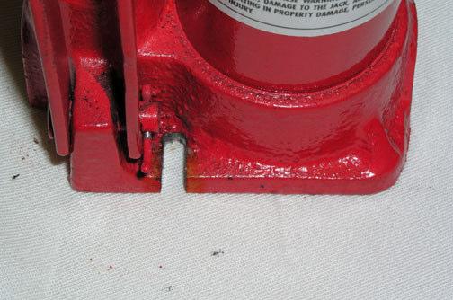
9 Figure 5. Press Arm End Cut Detailed Schematic Note in the photo above that the left-most hole is drilled for the eyebolt. The center hole is for the outer roller (I only drilled one I tailored this press for my bow), and the right-most hole is for the hinge bolt that attaches the arm to the main beam of the bow press. Figure 6. Main Press Beam End Cut Schematic The photo above shows the end cut detail of the press main beam. The inner roller is positioned in the beam toward the top of the photo. Note I labeled the hole 1 with a Sharpie that is so that when I disassemble the press I can match all the pieces back to their corresponding holes. My first time doing so with unlabeled parts was by trial and error for matching legs, feet, arms, and orientation. The holes are close, but no two are exactly in the same position. Hence the labels. 9


10 Figure 7. Press Arm Detailed Schematic Eyebolt attached to arm with cable Figure 8. Press Base Side View Schematic Drill the 1/2" holes for rollers in the main beam in positions that will work for your bow. The positions depicted above may or may not be optimal for your bow. Call your manufacturer and ask where to best position the inner rollers on the riser for your bow. Picture of leg meeting foot and bolt used to attach the two. The joint at the top of the leg attaching it to the main beam is similar the leg fits inside the main beam and the two are bolted together. 10

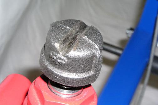
11 Figure 9. Bottle Jack Holes/Channels and Pipe End Cap Left: black pipe end cap with groove ground in to serve as a channel for the cable. 11


.")

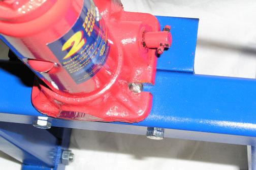
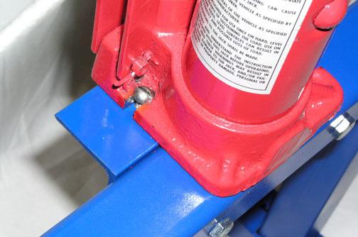
12 Figure 10. Press Base Top View Schematic Jack support above. The leftmost and center bolts shown attach the angle iron to the main beam. Note the hole drilled in the top of the angle iron and in the top of the main beam are used to attach the bottle jack (shown left and below). Picture to left shows bottle jack bolt does not interfere with angle iron bolt on right measure both for hole position before drilling and after bottle jack notches are cut. Left picture shows press and jack from the front. 12

 and Bow 13")
13 Figure 11. Devin Smith s Completed Press (Welded) Figure 12. Devin Smith s Completed Press (Welded) and Bow 13
OPERATIONS MANUAL. Port-O-Slitter
 Tapco Products Company The World Leader in Specialty Tools for the Professional Port-O-Slitter OPERATIONS MANUAL General instructions, set up, accessories and guide to using your portable precision slitting,
Warnings. Description. Prior to Installation Tools Needed
 Warnings Failure to act in accordance with the following may result in death or personal injury. The JT Strong Arm Stabilizer System is intended to eliminate chassis movement in travel trailers and fifth
OPERATIONS MANUAL. Port-O-Slitter
 OPERATIONS MANUAL Port-O-Slitter General instructions, set up, accessories and guide to using your portable precision slitting, rib forming and perforating system Saves hours on large siding jobs! Featuring:
Sheet Metal Brake Plans for a 6' Sheet Metal Brake
 Sheet Metal Brake Plans for a 6' Sheet Metal Brake,1752'8&7,21 Thank you for purchasing the sheet metal brake plans. The plans include a complete list of material needed and easy to follow steps to build
MODEL T28173/T28174 ROLLER TABLES INSTRUCTIONS
 MODEL T28173/T28174 ROLLER TABLES INSTRUCTIONS FOR MODELS MFD. SINCE 10/17 For questions or help with this product contact Tech Support at (570) 546-9663 or techsupport@grizzly.com Rails Rollers Reversible
Salter Industries Spiral Stair
 Salter Industries Spiral Stair The Leader in Spiral Staircases Continuous Sleeve Stair Installation Instructions TOOLS NEEDED: 1. Electric drill with hex chuck and Phillips bit 2. Drill bits 1/8", 1/4",
SWAG AIR-HYDRO RAM MOUNT ASSEMBLY INSTRUCTIONS
 SWAG AIR-HYDRO RAM MOUNT ASSEMBLY INSTRUCTIONS Tools needed for assembly: 5/16 HEX KEY WRENCH ¼ HEX KEY WRENCH ¾ SOCKET AND WRENCH 1.125 SOCKET HAMMER FLAT SCREW DRIVER GREASE FOR ASSEMBLY Step #1 Disassemble
HMP-200 BENDER INSTRUCTION SET
 HMP-200 BENDER INSTRUCTION SET HMP-200 BENDER ASEMBLY INSTRUCTIONS STEP 1 STEP 2 BOLT LEFT SIDE PLATE TO BASE AS SHOWN WITH 1/2 x20 HEX BOLT & FLAT WASHER WELD BASE TO PLATE ON EACH SIDE NOTE: OFFSET HOLE
The Queen Quilter Professional Quilters Kit Frame
 The Queen Quilter Professional Quilters Kit Frame Assembly Instructions Table of Contents: Before you begin......................... Pg. 2 Wood parts............................. Pg. 3 Hardware..............................
Type 316SS Backed Conveyor Strip Brush Nylon Bristles, 6" O'all HT, 2' Lg, 3/16" Backing
 How to modify your MK101. First off, the MK101 tile saw is a fantastic tile saw, without any modifications what so ever. That being said, all tile saws tend to have a significant amount of overspray which
STEEL RULE. Stock TRY SQUARE
 FITTING INTRODUCTION Fitting consists of a handwork involved in fitting together components usually performed at a bench equipped with a vice and hand tools. The matting components have a close relation
INSPECTION AND CORRECTION OF BELLHOUSING TO CRANKSHAFT ALIGNMENT
 INSPECTION AND CORRECTION OF BELLHOUSING TO CRANKSHAFT ALIGNMENT BACKGROUND Proper alignment of the transmission input shaft to the crankshaft centerline is required in order to achieve the best results
Hatchback Wing Riser Kit
 Hatchback Wing Riser Kit 2015-06-11 Thank you for purchasing this PERRIN product for your car! Installation of this product should only be performed by persons experienced with installation of aftermarket
EllisSaw.com. EllisSaw.com P.O. Box Verona, WI
 P.O. Box 9019 Verona, WI 9-019 GENERAL OPERATING & SAFETY INSTRUCTIONS * READ INSTRUCTIONS BEFORE USE * CAUTION: Disconnect power supply cord from power source when doing repair work or changing belt.
Bendarc. Assembly Instructions. <<< Remove 5" pivot. Move the roller to the correct hole for your radius. (use 3/4" wrench)
") Bendarc Assembly Instructions
Bendarc Assembly Instructions
Lumber Smith. Assembly Manual. If you are having problems assembling the saw and need assistance, please contact us at:
 Lumber Smith Assembly Manual If you are having problems assembling the saw and need assistance, please contact us at: 804-577-7398 info@lumbersmith.com 1 Step 1 Safety Carefully read the Owners Manual.
Downtown Rack. Custom logo option available
 Custom logo option available Downtown Rack The Downtown Rack uses thick, square-tube construction that can t be cut with a pipe cutter. The extended width of the Downtown Rack makes for easy bike parking
CUT OUT FLARES INSTALLATION INSTRUCTIONS FOR 20017, 20018, F100-F150 F250-F350 P.U. & BRONCO CUT OUTS
 20017 04/22/03 REV-A CUT OUT FLARES INSTALLATION INSTRUCTIONS FOR 20017, 20018, F100-F150 F250-F350 P.U. & BRONCO CUT OUTS Tools Required for Installation: (A) 3/16 Drill Bit (B) Pop-Rivet Gun (C) Air
BEAST THE. Tube and Pipe Notcher Operating Instructions. Notches In Bends Straight Notches. Angled Notches. Offset Notches
 Copyright (c) 2007 J D SQUARED INC. www.jd2.com THE BEAST Tube and Pipe Notcher Operating Instructions Notches In Bends Straight Notches Angled Notches PATENT PENDING Offset Notches Assembly After unpacking
Swerve Rack CUSTOM RACKS AVAILABLE
 CUSTOM RACKS AVAILABLE Swerve Rack The design of the Swerve mirrors the bike frame, thus providing superior bike support while making it easy to secure both the bike frame and wheel with a standard u-lock.
1984 to ZX (Z31) Rear Camber Modification Gary Molitor, March 1, 2009
 Rear Camber Modification Gary Molitor, March 1, 2009") 1984 to 1989 300ZX (Z31) Rear Camber Modification Gary Molitor, March 1, 2009 Step 1: Bushing Removal After removal of the rear suspension and disassembly of all the parts, the first thing I did was remove
1984 to 1989 300ZX (Z31) Rear Camber Modification Gary Molitor, March 1, 2009 Step 1: Bushing Removal After removal of the rear suspension and disassembly of all the parts, the first thing I did was remove
What is a fastener? A device to locate or hold parts
 What is a fastener? A device to locate or hold parts As a repair technician you will become skilled at removing, reconditioning, replacing, and installing fasteners. An important skill to learn is how
Mounting the 6 or 12 Indexer on PRS Gantry Tools
 Page 1 Mounting the 6 or 12 Indexer on PRS Gantry Tools About this guide: This document illustrates several options for mounting an indexer onto your ShopBot. You can choose the technique that works best
Kromski Minstrel Assembly Instructions
 Kromski Minstrel Assembly Instructions Important Notice If you have any difficulty in understanding these instructions, assembling the wheel, or having it operate to its fullest potential, WE WANT YOU
Free Standing Frame and Canopy
 Patriot Docks Free Standing Frame and Canopy Required Tools: Cordless Drill, 3/8 drill bit, 17mm wrench, 18mm wrench, 6mm hex key (included), 8mm hex key (included) Helpful Tips: Assembling and installing
Clayton Off Road COR COR COR
 Clayton Off Road COR-4806011 COR-4806021 COR-4806031 JEEP GRAND CHEROKEE WJ LONG ARM UPGRADE KITS (1999-2004 WJ) NOTES: This product requires general welding, fabrication and automotive mechanic skills.
Side Winder R o u t e r L i f t.
 Woodpeckers PRECISION WOODWORKING TOOLS Side Winder R o u t e r L i f t. INSTALLATION INSTRUCTIONS The wrench handle must be pointing left in order to fully insert or remove it. Lift Wrench Once fully
Hydraulic Clamp Carrier. Installation & Operation Manual
 Hydraulic Clamp Carrier Installation & Operation Manual Hydraulic Clamp Carrier Installation & Operation Manual Quick Machinery Company 8272 Peninsula Drive Kelseyville, CA 95451 phone: (707) 272-6719
Required Tools: Procedure:
 Depending on the materials you process through your chipper, their moisture content, the climate you live in, and many other factors you may have difficulty removing the rotor from the engine shaft. The
INSTALLATION INSTRUCTIONS CHEVY C-10 INDEPENDENT FRONT SUSPENSION
 INSTALLATION INSTRUCTIONS 73-87 CHEVY C-10 INDEPENDENT FRONT SUSPENSION Please read these instructions completely before starting your installation. Assemble suspension on vehicle before powder-coating
1949 to 1954 Chevrolet Dual Master Cylinder Conversion
 1949 to 1954 Chevrolet Dual Master Cylinder Conversion This document is a one stop shop to getting your brake system updated on your old Chevy. Whether you re going with a disc conversion or just sticking
The DeltaGrip System. Safety and Operating Instructions. Trigger. Air Supply Connection. Handle Assembly. Air Line Assembly.
 The DeltaGrip System Safety and Operating Instructions Trigger Air Supply Connection Handle Assembly Air Line Assembly Punch Die Pneumatic Diaphragm Assembly Shackle, Pin & Jam Nut Jaw Frame Shoulder Screw
H O O P RAC K. Simple Security
 H O O P RAC K Simple Security The Hoop Rack is a proven design that provides high security and easy bike parking. The Hoop Rack uses thick pipe construction and the full radius of the bend makes the Hoop
8-Ton Manual Splitter OWNER S MANUAL
 8-Ton Manual Splitter OWNER S MANUAL WARNING: Read carefully and understand all ASSEMBLY AND OPERATION INSTRUCTIONS before operating. Failure to follow the safety rules and other basic safety precautions
Cabinet is 90% assembled, all you need to do is to attach the legs, lay the glass top on the cabinet, connect the faucet, drains & ptrap.
 Things you might need for the installation: vessel sink, plumber's putty(home depot), liquid nails(home depot), Bucket silicone caulk(home depot), Putty knife Plumber's putty Pipe wrench Channel-lock pliers
PRO Series Brakes Operating Instructions
 PRO Series Brakes Operating Instructions Tapco Products Company PRO Brake System PRO Cut Off Gauge Simplifies cutting. PRO Cut-Off Quickly, safely, and easily makes factory quality cuts in coil stock,
S W E RV E RAC K. Simple Security. Simple Stability.
 S W E RV E RAC K Simple Security. Simple Stability. The Swerve Rack is a proven design that provides high security and easy bike parking. The Swerve Rack uses thick pipe construction and the full radius
Kwik-Lock. Installation Instructions. Attention Dealers: Please give this owners manual to the customer when the product is delivered.
 Serving the Truck & Trailer Industry Since 1944 Installation Instructions Attention Dealers: Please give this owners manual to the customer when the product is delivered. Call 800-535-9545 www.aeroindustries.com
How to Build a Structure Tester
 This material was originally authored by: Bill Allen, Orville Wright Williamson and Rick Rand It was revised on 10/17/02,12/17/03 and 11/30/04 by Victor Tom How to Build a Structure Tester Introduction
Sunrise Deck Assembly Instructions for Kingston Left
 Sunrise Deck Assembly Instructions for Kingston Left It s easiest to build the deck frame first like it will be lying on its back and then after all 4 legs and horizontals are in place, tip the deck toward
What is a fastener? A device to locate or hold parts
 What is a fastener? A device to locate or hold parts As a repair technician you will become skilled at removing, reconditioning, replacing, and installing fasteners. An important skill to learn is how
6625 WEST WILSHIRE BLVD. OKLAHOMA CITY, OK (405) FAX (405)
 FAX (405)") INSTALLATION INSTRUCTIONS FOR THE TAILGATE WITH LATCH AND LINK ASSEMBLY 76-87 FORD SHORT & 53-87 FORD LONG FLARESIDES 1. Assemble the bed and make sure the box is square. Measure the distance between the
INSTALLATION INSTRUCTIONS FOR THE TAILGATE WITH LATCH AND LINK ASSEMBLY 76-87 FORD SHORT & 53-87 FORD LONG FLARESIDES 1. Assemble the bed and make sure the box is square. Measure the distance between the
INSTALLATION INSTRUCTIONS FORD F-100 INDEPENDENT FRONT SUSPENSION
 INSTALLATION INSTRUCTIONS 65-79 FORD F-100 INDEPENDENT FRONT SUSPENSION Please read these instructions completely before starting your installation. Assemble suspension on vehicle before powder-coating
Norman's Grizzly G0602 Reverse Tumbler Plans
 Norman's Grizzly G0602 Reverse Tumbler Plans Pictures taken by Norman Author Norman here is the photos of the change gears for the G0602 lathe. reverse turning to the right or for left hand threads netural
Assembly Instructions: Bencher Skylark
 Assembly Instructions: Bencher Skylark Tools Required: Pop Rivet Tool Tape Measure Hex Wrenches Screwdriver Several Disposable Rags Two Saw Horses Several boxes or bowls to hold fasteners and small parts
Locker Pedestal Installation Instructions
 Locker Pedestal Installation Instructions LK-PED-INST-0314r1 Parts List Single Pedestal Back to Back Pedestal Horizontal Support Tube TS-169 Post Flange TS-190 Post Cap Fasteners Provided: #8 x ¾ round
Brochure Includes: Set-up Instructions Operating Instructions Parts List Fundamentals of Drill Sharpening. Patent 3,952,459
 Patent 3,952,459 Brochure Includes: Set-up Instructions Operating Instructions Parts List Fundamentals of Drill Sharpening Accurately Sharpens most drills bits. Now, with this one low-cost, simple machine,
Make a Safe. Description. Lesson Objectives. Assumptions. Terminology
 Youth Explore Trades Skills Make a Safe Description Welding is a vast area in the metalworking field and a widely used joining process for metal. In this activity plan students will learn how to MIG weld
Hose Hanger Cold Metal Work
 Hose Hanger Cold Metal Work Name: Date: Description: A cold metal project that gives students practice sheering, bending, drilling, and fastening steel. The hose hanger can be used for proper storage of
GENERAL OPERATIONAL PRECAUTIONS PRECAUTIONS ON USING DISC GRINDER
 GENERAL OPERATIONAL PRECAUTIONS WARNING! When using electric tools, basic safety precautions should always be followed to reduce the risk of fire, electric shock and personal injury, including the following.
Grade 8 Enriched Math Catapult Project 2012 Step by Step Instructions to building a catapult
 Grade 8 Enriched Math Catapult Project 2012 Step by Step Instructions to building a catapult Grade 8 Enriched Math Project INSTRUCTION SHEET FOR CATAPULT Procedures, materials and tools: below is a step-bystep
General Guidelines:
 ASSEMBLY INSTRUCTIONS Congratulations on your new Patriot Dock purchase. This manual contains instructions to assemble basic dock configurations for use at typical residential shoreline application. Please
The NorCal Paddle Kit
 The NorCal Paddle Kit designed by Wayne Smith, K8FF Winner of the 1997 NorCal Design Contest Kitted by the NorCal QRP Club Copyright 1997 All Rights Reserved. This manual is copyrighted by Doug Hendricks
Pneumatic Clamp Carrier. Installation & Operation Manual
 Pneumatic Clamp Carrier Installation & Operation Manual Pneumatic Clamp Carrier Installation & Operation Manual Quick Machinery Company 8272 Peninsula Drive Kelseyville, CA 95451 phone: (707) 272-6719
installation guide 1 GUIDE#: pwb-assault-001
 assault WAKEBOARD tower installation guide INSTALLATION SUPPORT 1 important information This Aerial wakeboard tower fits motor boats with 76-108 inch wide beam widths. This measurement is taken from the
Factory Assistance: Phone: Fax: Page 1
 CABLE RUNWAY ACCESSORIES Radius Drop / Stringer Drop Provides 3 bend radius Radius drop fits 6, 12 and 18 runway made from 1-1/2 x 3/8 tubing Steel construction Includes (3) cable spools, (1) bolt, (1)
Plans & Materials List for Handwashing Station
 Plans & Materials List for Handwashing Station Required Tools Arc Welder (mig or stick) Chop or metal band saw Grinder (bench and/or handheld) 3/8" Drill 1/8", 1/4", 5/16" Drill Bits Copper Pipe Cutter
Rudders Removal and Stuffing Box Packing by Brian Barton May 31, 2013
 Rudders Removal and Stuffing Box Packing by Brian Barton May 31, 2013 Last year both rudders on my 38 Commander were leaking a little less than a water fall. An adjustment worked on the starboard side.
SmartShift for A1 Chasis Install Guide
 SmartShift for A1 Chasis Install Guide SmartShift is designed for drivers who want the precision and positive feel that only a spherical bearing linkage can deliver. These systems work with all Mk1, Mk2,
RACER TECH COMMANDER HD TIE ROD INSTALLATION
 RACER TECH COMMANDER HD TIE ROD INSTALLATION NOTE: These instructions are a universal explanation of how to install our HD Tie Rods. All kits are identical for all inner joints and nearly identical for
ROOP LAL Unit-6 Drilling & Boring Mechanical Engineering Department
 Lecture 4 Notes : Drilling Basic Mechanical Engineering ( Part B ) 1 Introduction: The process of drilling means making a hole in a solid metal piece by using a rotating tool called drill. In the olden
UNPACK & ASSEMBLY. Done! CAUTION! THE MILL WILL BE VERY HEAVY - GET ASSISTANCE Pepe Tools.
 PARTS DIAGRAM T Bar Height adjustment Wooden hand grip Height adjustment gears Frame Height adjustment screws Top roller End Gears cover Handle Brass Bushes (Each side) Bottom roller 4:1 Gearbox Mounting
Kentucky 4H Wood Science Plans Notebook. Plans Level 3
 Kentucky 4H Wood Science Plans Notebook Plans Level 3 MATERIALS: 2 pieces wood 3/4 x 10 x 4 1 piece wood 3/4 x 12 x 4 2 pieces wood 3/4 x 3 x 2 5 1/2" 2 pieces wood 3/4 x 3 x 1 8 1 piece wood 2 x 4 x
INSTRUCTION MANUAL DWX723-XE HEAVY-DUTY MITER SAW STAND FINAL PAGE SIZE : 8.5IN X 5.5IN
 INSTRUCTION MANUAL DWX723-XE HEAVY-DUTY MITER SAW STAND FINAL PAGE SIZE : 8.5IN X 5.5IN DWX723-XE MITER SAW STANDS Components List A. Beam B. DW7231 Miter saw mounting brackets C. Extension arm D. DW7232
INSTRUCTION SHEET. PIECE INVENTORY - MOBILE BASES Refer to the diagram for part identification.
 INSTRUCTION SHEET D2260 HEAVY-DUTY MINI-MOBILE BASE D2057 HEAVY-DUTY MOBILE BASE D2058 SUPER HEAVY-DUTY MOBILE BASE D2259 EXTENSION KIT FOR D2260/D2057 D2246 EXTENSION RAIL KIT FOR D2058 This Shop Fox
Be sure any accessory used will fit with the soft upper doors before installing. Not all accessories will be compatible.
 Company Name: Spike Power Sports Vehicle Name: Polaris General 2P Product Description: Soft Upper Doors Part Number: 58-1600 Revision: R01 09/19/2018 Contents: 655 Elm Ridge Ave, Canal Fulton OH, 44614
Installation Instructions Universal Crossmember Kit - 60 Track Width BEFORE Measure Twice, Weld Once! II
 Installation Instructions Universal Crossmember Kit - 60 Track Width Please read these instructions completely BEFORE starting your installation. Remember the basic rule for a successful installation:
ASAP Sr. A Strap and Pole. Magic Christmas. Single Stage. Walter Monkhouse. Alexandria, La. Version 1.2.
 ASAP Sr Single Stage A Strap and Pole Version 1.2 Walter Monkhouse Walter@MagicChristmas.org Magic Christmas Alexandria, La. Description The ASAP Sr, single stage, has the same concept as the ASAP Jr.
MINI-LATHE QUICK CHANGE TOOL POST
 MINI-LATHE QUICK CHANGE TOOL POST Cutting and assembly details Machinists should familiarize themselves with the contents of this section before jumping in to the drawings. Many details are described here
8030 Synergy Jeep JK Rear Long Arm Frame Brackets
 General Notes: SYNERGY MFG. 870 INDUSTRIAL WAY, SAN LUIS OBISPO, CA (805) 242-0397 8030 Synergy Jeep JK Rear Long Arm Frame Brackets These instructions are also available on our website; www.synergymfg.com.
WARNING Indicates a hazardous situation which, if not avoided, could result in death or serious injury. WARNING. Ranger XP Door Kit
 REVISION 04 November, 20 2018 Ranger XP Door Kit Prior to installation, please verify if a revised version of this instruction sheet is available on Knowledge Center. The following symbols may be used
30DC Speed Lathe Manual
 30DC Speed Lathe Manual The Crozier Model 30DC Speed Lathe is our most popular model. It has many standard features not found on any other machine in its class or price range. Standard Features 3/4 HP
SAFETY INSTRUCTIONS. Wear protective clothing, including safety glasses and steel toe boots.
 SAFETY INSTRUCTIONS Wear protective clothing, including safety glasses and steel toe boots. DO NOT allow loose clothing or long hair near machine operations. Keep work site and machine clean. Use brush
Agricultural Mechanics and Technology Power Tool Safety Rules
 Agricultural Mechanics and Technology Power Tool Safety Rules Name: BAND SAW Use: Cutting curves, circles and irregular shapes. 1. Use clean SHARP blades. 2. The teeth should always point DOWN. 3. Adjust
Parts list Instruction guide Warnings Please read carefully before assembling and using product.
 Parts list Instruction guide Warnings Please read carefully before assembling and using product. Jet Rail XL Part Number 27377 Tools required for assembly Hammer 9/16 Wrench 3/4 Wrench Ratchet 9/16 Socket
Quick-Release Front Vise 05G34.01
 Quick-Release Front Vise 05G34.01 Patent Pending Introduction A front vise is the most generally useful vise on a typical workbench. It can be used for clamping parts on edge within the jaws, for clamping
H O O P RAC K. Simple Security
 H O O P RAC K Simple Security The Hoop Rack is a proven design that provides high security and easy bike parking. The Hoop Rack uses thick pipe construction and the full radius of the bend makes the Hoop
Potter s Wheel Plans. Flywheel is poured in form made by tacking tar paper to plywood disk. Partly set concrete is broom-finished.
 Potter s Wheel Plans Flywheel is poured in form made by tacking tar paper to plywood disk. Partly set concrete is broom-finished. Throwing Pottery on a wheel is the most challenging form of pottery making
Mast and Antennas for Field Day & Emergencies
 Mast and Antennas for Field Day & Emergencies John A. Allocca, WB2LUA, July 2005 This is a 27 feet 1.5 diameter portable guyed mast with a 28 feet diameter footprint. It breaks down into four 6 feet sections
Clock 35 - Toyland. Construction instructions for Clock 35
 This clock has been designed for children, it is a stand-alone unit and can be positioned on a shelf or cabinet out of the reach of very young hands who may be tempted to touch. The clock is shown in two
12 Slip Roll. Model Assembly & Operating Instructions
 12 Slip Roll Model 36698 Assembly & Operating Instructions Diagrams within this manual may not be drawn proportionally. Due to continuing improvements, actual product may differ slightly from the product
Clocking a TD-04 Turbo Compressor Housing. Appendix A : AWIC Silicone and Tubing Fitting
 Clocking a TD-04 Turbo Compressor Housing Appendix A : AWIC Silicone and Tubing Fitting Revision A: 7-13-2015 Tools: Metric Sockets (10, 12, 14, 17mm) 5mm Hex Key Large Internal Snap Ring Pliers 3/8 Socket
GENERAL OPERATIONAL PRECAUTIONS PRECAUTIONS ON USING CUT-OFF MACHINE
 GENERAL OPERATIONAL PRECAUTIONS WARNING! When using electric tools, basic safety precautions should always be followed to reduce the risk of fire, electric shock and personal injury, including the following.
Leafy Greens Spinner Construction Manual
 Leafy Greens Spinner Construction Manual University of Houston Conrad N. Hilton College Food Science Lab Materials list: Base and Armature Approximately 8-1 PVC cut into sections o 3-22.5 o 2-7 o 2-4 o
Bend-Tech Dragon Assembly Manual
 p.1 Bend-Tech Dragon Assembly Manual IMPORTANT: Please read before unpacking. Place shipping container in a wide open area where you will have room to work and assemble this product. Shipping The Dragon
TOOL LIST FOR TAILGATE HIDDEN LATCH & LINK ASSY FOR FORD FLARESIDE TRUCKS
 TOOL LIST FOR TAILGATE HIDDEN LATCH & LINK ASSY FOR 53-87 FORD FLARESIDE TRUCKS Vise Grip Clamps C-clamps Sharpie Marker Ball Peen Hammer Center Punch 3/8 or 1/2 Drill 5/32, 7/32, 9/32, and 3/8 Drill Bits
DIY Lowery Inspired Embroidery Floor Stand
 DIY Lowery Inspired Embroidery Floor Stand Below find the details on how to build your own embroidery floor stand. The Lowery Floor Stand inspired this design. Note using the following instructions will
M2 Antenna Systems, Inc. Model No: 20M5LD
 M2 Antenna Systems, Inc. Model No: 20M5LD SPECIFICATIONS: Model... 20M5LD Frequency Range... 14.0 14.350 MHz *Gain (Full Band)... 10.2 dbi Typical Front to back... 23 db Typical Beamwidth... E=50 / H=66
installation guide 1 GUIDE#: pwb-wwtowv1-pol-003
 g300 WAKEBOARD tower installation guide INSTALLATION SUPPORT 1 important information This WakeWorks wakeboard tower fits motor boats with 76-108 inch wide beam widths. This measurement is taken from the
Spiral Slide
 IMPORTANT Page 1 PLEASE READ THESE INSTRUCTIONS BEFORE COMMENCING ASSEMBLY. All equipment must be installed in accordance with these instructions. Check your shipment against Bill of Lading and Parts list.
INSTALLATION MANUAL IOWA MOLD TOOLING CO., INC. BOX 189, GARNER, IA MANUAL PART NUMBER:
 PARTS-1 Model 24562/28562 Crane INSTALLATION MANUAL IOWA MOLD TOOLING CO., INC. BOX 189, GARNER, IA 50438-0189 641-923-3711 MANUAL PART NUMBER: 99903701 Iowa Mold Tooling Co., Inc. is an Oshkosh Truck
installation guide
 JANUS INTERNATIONAL 1 866 562 2580 w w w. j a n u s i n t l. c o m 2000 2500 3000 installation guide RIGHT DRIVE END SHOWN LH OPPOSITE LEFT TENSION END SHOWN RH OPPOSITE PUSH-UP OPERATION 2000 2500 3000
PRO Brake Operating Instructions
 PRO Brake Operating Instructions Tapco Products Company P R O 9 a n d P R O B r a k e s PRO Brake System PRO Cut Off Gauge Simplifies cutting. PRO Cut-Off Quickly, safely, and easily makes factory quality
Pneumatic Clamp Carrier. Installation & Operation Manual
 Pneumatic Clamp Carrier Installation & Operation Manual Pneumatic Clamp Carrier Installation & Operation Manual Quick Machinery Company 8272 Peninsula Drive Kelseyville, CA 95451 phone: (707) 272-6719
BMW E46 Coupe 3dr MP Bolt in (BMW Race Days Only) Roll Cage (B045) Fitting Instructions
 Roll Cage (B045) Fitting Instructions") BMW E46 Coupe 3dr MP Bolt in (BMW Race Days Only) Roll Cage (B045) Fitting Instructions Unwrap the mounting points/ends of the roll cage and unpack the individual fitting kits. Try to leave wrapping on
BMW E46 Coupe 3dr MP Bolt in (BMW Race Days Only) Roll Cage (B045) Fitting Instructions Unwrap the mounting points/ends of the roll cage and unpack the individual fitting kits. Try to leave wrapping on
Giraud Tool Company, Inc.
 Motor Upgrade for Gracey Trimmer This package is intended to allow the user to upgrade their Gracey trimmer with a higher rpm motor and convenience features not found in the production offering. This upgrade
PACKING LIST MACO V-5000
 PACKING LIST MACO V-5000 PART QTY O.D. SIZE LENGTH DESCRIPTION CHECKLIST T47P 4 5/8.050 36 Aluminum Tubing _ T43P 1 7/8.050 48 Aluminum Tubing _ T18P 1 3/4.050 48 Aluminum Tubing _ T15P 1 5/8.050 48 Aluminum
Instruction Manual for MHE Products DeepWater2 PushPoint Sampler Ver. 2.0 November 21, 2016
 Instruction Manual for MHE Products DeepWater2 PushPoint Sampler Ver. 2.0 November 21, 2016 The DeepWater2 is heavier-duty a version of the PushPoint Sampler made of stainless steel pipe instead of SS
Metal Shapers Forums and Tech Rodding Roundtable Home Forums Events Members Webring Tech Merchandise Contact Chat Services Links Want Ads Advertising
 Metal Shapers Forums and Tech Home Forums Members Webring Tech Contact Chat Services On the following pages your will find detailed instructions on the parts needed and assembly instructions for a 12"
ASSEMBLY INSTRUCTIONS FOR MAR-K BEDSIDES AND GM FLUSH TAILGATE WITH HANDLE
 ASSEMBLY INSTRUCTIONS FOR MAR-K BEDSIDES AND 41-53 GM FLUSH TAILGATE WITH HANDLE Build the box assembly according to the MAR-K assembly instructions. When installing the tailgate and latching mechanisms