Installation Guide. Spherosyn & Microsyn Linear Encoders
|
|
|
- Kelley Hodge
- 6 years ago
- Views:
Transcription


1 Installation Guide Spherosyn & Microsyn Linear Encoders
2 Contents CONTENTS 1. Introduction 1.1 Brackets 1.2 Preparation 1.3 Warnings 2. Spherosyn Encoder Assembly 3. Microsyn Encoder Assembly 4. Mounting the Reader Head 4.1 Spherosyn 4.2 Microsyn 5. Mounting the Scales and Support Brackets 5.1 Spherosyn Double End Mounting Single End Mounting Encoders in Excess of 2.5 metres 5.2 Microsyn Single End Mounting 6. Mounting the guard 7. Cable routing 8. Final check APPENDICES 2 Newall Measurement Systems
3 Introduction 1.0 INTRODUCTION This manual will provide mounting instructions for Newall's Spherosyn and Microsyn Linear Encoders. It is important that you read and understand this manual prior to beginning the installation. If at any time during the installation you should have any questions, contact Newall or your local authorised representative. 1.1 Brackets Due to the variety of machine types and applications, it will be necessary to design, make and fit custom brackets for the encoder assembly. If brackets are needed make certain they are rigid enough not to allow any flexing or distorting while the machine is in operation. Newall offers a variety of bracket kits to aid in the installation. Contact Newall or your local authorised representative for details. 1.2 Preparation Prior to beginning the installation the machine should be studied to determine where the Encoder(s) will be fitted. For best results, it is recommended that the Encoder be fitted as close to the machine lead screw or axial drive shaft as possible. Spherosyn: Overall Length = Travel + 258mm (10.2 ) Microsyn: Overall Length = Travel + 173mm (6.8 ) Outboard mounting of the scale support brackets will add approximately 20mm (3/4") to the stated travel. (Refer to Appendix A & B) For a more compact installation, scale travels of 300mm (12") or less may be fitted by supporting one end of the scale only by use of a single end mounting block. (Refer to Figure 5.4 and 5.10) The moving member of the Encoder assembly can be either the Reader Head or the Scale. Cable routing from the Reader Head should be examined (See Section 7). Each Reader Head is provided with either a 3.5 metre (11 ), 7 metre (22 ) or 10 metre (33 ) of armoured cable. Extension cables are available in 1 metre (3'), 2 metre (6'), 3.5 metre (11.5'), 5 metre (16.5') and 10 metre (32') lengths. Contact Newall or your local authorised representative for details. For Encoders larger than 1500mm (60 ) travel, a setup tube (blank scale) is recommended. 1.3 Warnings If for any reason the machine axis travel is greater than the actual scale travel it is recommended that 'mechanical stops' are fitted to the machine to avoid damage caused by over travel. Newall will not accept responsibility for Scale and Reader Head damage caused by machine over travel. Both the Reader Head and the Scale are precision made components and it is important that they are handled with care. By design the Encoders can withstand the rigours of the harsh workshop environment. However, permanent damage can occur through bending or severe impact. It is important that the Scale be kept at least 13mm (0.5") away from any magnetic bases on indicators or magnetic chucks. Newall Measurement Systems 3
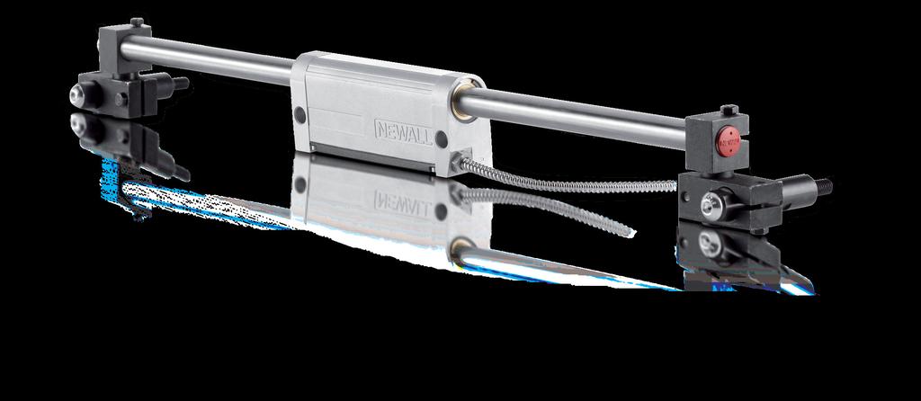
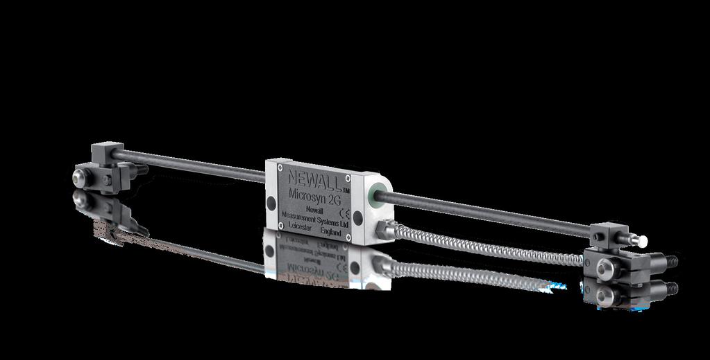
4 Encoder Assembly 2.0 SPHEROSYN ENCODER ASSEMBLY (<2.5m/100 ) M / Item Description Qty 1 Spherosyn Reader Head 1 2 Spherosyn Scale 1 3 Scale Support Link 2 4 Scale Anchor Pin 2 5 Support Pillar Short 2 Item Description Qty 6 Support Pillar Long 2 7 Scale Cover 1 8 M5 x 20 Hex Head 6 9 M8 x Socket Button Head 2 10 Spacer Washer MICROSYN ENCODER ASSEMBLY M / Item Description Qty 1 Microsyn Reader Head 1 2 Microsyn Scale 1 3 Scale Anchor pin 1 4 M3 x 16 SHCS 1 5 M3 Spring Washer 1 6 Scale Support Pin 1 7 M4 x 5 Nylon Set Screw 1 Item Description Qty 8 Support Link 2 9 M3 x 12 Hex Screw 4 10 M3 x 12 SHCS 4 11 M6 x 10 Socket Button Head 2 12 Support Pillar Short 2 13 Support Pillar Long 2 14 Spacer Washer 2 15 Scale Cover 1 4 Newall Measurement Systems
 to the machine and secure")
 Figure 4.")


5 Mounting the Reader Head 4.0 MOUNTING THE READER HEAD 4.1 Spherosyn Mount the Reader Head together with its bracket(s) to the machine and secure the assembly parallel with axis travel to within +/-0.05mm (0.002"). (Refer to Figure 4.1) Figure Alignment of the Spherosyn Reader Head Final adjustments can be carried out by use of laminated shims, which are included with each encoder assembly. Each layer of shim is equivalent to 0.05mm (0.002"). 4.2 Microsyn Figure Alignment of the Microsyn Reader Head Mount the Reader Head together with its bracket(s) to the machine and secure the assembly parallel with axis travel to within 0.05mm (0.002"). (Refer to Figure 4.2) Newall Measurement Systems 5
6 Mounting the Scale 5.0 MOUNTING THE SCALE 5.1 Spherosyn Double End Mounting Note: Refer to section for mounting scales in excess of 2.5 metres. Each end of the Spherosyn Scale is different and can be identified by the red cap screw at the 'tensioner end' and a nylon snap rivet at the 'fixed end'. 16mm EFFECTIVE TRAVEL LIMITS 30mm FIXED END TENSIONER END Figure Spherosyn Scale NOTES: (A) (B) Erroneous readings will occur if the Reader Head is allowed to travel beyond the Effective Travel Limits. (Refer to Figure 5.1) The pre-load on the balls are factory set via the set screw at the tensioner end. Do not tamper with or adjust the set screw as this will alter the calibration and accuracy specification of the scale. (Refer to Figure 5.1) Once the Reader Head is secured and correctly aligned, the scale support brackets can now be fitted. The scale support brackets consist of the support pin, the support link and the pillar(s). Traverse the machine to its maximum position toward the non-cable entry side of the Reader Head. Maximum position means all available travel, including hand winding past any electrical limits or trip dogs. Carefully slide the blank scale (or Spherosyn scale if less than 1500mm (60") travel), allowing for a sufficient amount of scale to project from the Reader Head in order to fit the scale support brackets. Assemble the scale support link to the scale support pin leaving approximately 3mm (1/8") gap between the bottom of the pin shoulder and the top of the link. Slide the link/pin assembly onto the scale to approximately 5mm (0.2") away from the end of the Reader Head. Transfer punch through the support link and into the machine casting. It is important that the support link is kept square to its mounting surface at all times. Remove the link/pin assembly and the scale from the Reader Head. Drill and tap M8 x 18mm deep into the machine casting as marked by the transfer punch. Fit the pillar(s) to the machine casting by using one of the methods shown in Figure 5.3. The pillar should fit square and flush to the machine surface. 6 Newall Measurement Systems
7 Mounting the Scale A maximum of two support pillars may be screwed together to allow for sufficient adjustment of the scale. If two pillars are insufficient to enable the scale to be mounted, then additional brackets will be necessary. These brackets must be sufficiently rigid to eliminate any axial movement of the scale. Loosely fit the support link/pin assembly onto the pillar and pass the scale through the Reader Head and into the support pin. While gently sliding the scale forward and back 25-50mm (1" - 2") through the support pin, carefully tighten the hex screws on the support link, ensuring that the scale slides smoothly through the Reader Head and into the support pin. If any interference is detected then fully loosen the hex screws on the support link and repeat this step. Note: Do not force the Scale through the Support Pin IMPORTANT WARNING: THE CENTRE LINE BORE OF THE READER HEAD MUST BE IN DIRECT ALIGNMENT WITH THE CENTRE LINE BORE OF THE SUPPORT PIN. PERMANENT DAMAGE TO SCALE AND/OR ERRONEOUS READER WILL OCCUR IF THIS WARNING IS NOT FOLLOWED. REFER TO FIGURE 5.2 Figure Reader Head and Bracket Alignment Remove the scale from the Reader Head and traverse the machine to its full extent in the opposite direction. Full extent means hand winding past electrical limits. Assemble the scale support link to the scale support pin leaving approximately 3mm (1/8") gap between the bottom of the pin shoulder and the top of the link. Slide the link/pin assembly onto the scale making certain that there is sufficient clearance between the Reader Head and the support link to prevent damage to the Reader Head cable. Do not secure the support pin to the scale at this time. Transfer punch through the support link and into the machine casting. It is important that the support link be kept square to its mounting surface at all times. Newall Measurement Systems 7
8 Mounting the Scale Remove the link/pin assembly and the scale from the Reader Head. Drill and tap M8 x 18mm deep into the machine casting as marked by the transfer punch. Fit the pillar(s) to the machine casting by using one of the methods shown in figure 5.3. The pillar shoulder fits square and flush to the machine surface. A maximum of two support pillars may be screwed together to allow for sufficient adjustment of the scale. If two pillars are insufficient to enable the scale to be mounted, then additional brackets will be necessary. These brackets must be sufficiently rigid to eliminate any axial or radial movement of the scale. Loosely fit the support link/pin assembly onto the pillar and pass the scale through the Reader Head and into the support pin. While gently sliding the scale forward and back 25-50mm (1" - 2") through the support pin, carefully tighten the hex screws on the support link, ensuring that the scale slides smoothly through the Reader Head and into the support pin. If any interference is detected then fully loosen the hex screws on the support link and repeat this step. Repeat the above steps at the other end of the machine. Then carefully slide the Spherosyn Scale through the support pin, through the Reader Head and into the opposite support pin. Tighten the hex screws on the anchor pins Single End Mounting Figure Support Pillars Note: The maximum total length of the scale must not exceed 610mm (24") when using a single end mounting kit. The single end mounting kit is sold separately, ask for UK part number , USA part number M. Remove the white rivet from the fixed end of the scale. After the Reader Head has been installed slide the scale through the Reader Head and insert the fixed end of the scale into the single end mounting block. (Refer to Figure 5.4) Once the position for the single end mounting block has been determined mark the machine casting using the slot in the mounting block as the guide. Drill and tap M6 x 12mm deep. Fit the mounting block using the M6 socket head cap screw and washer. Check the alignment by gently sliding the scale through the head and in and out of the mounting block, adjustments may be carried out by altering the M5 jacking screws. When the alignment is complete secure the scale by inserting the M5 screw and washer through the mounting block and into the fixed end of the scale. 8 Newall Measurement Systems
9 Mounting the Scale Single End Mounting Block Jacking Screws M5 Fixing Slot for M6 Screw Figure Spherosyn Single End Mounting Scales in Excess of 2.5 Metres (100 ) Traverse the machine to fullest extent of travel including hand winding past any electrical limits or trip dogs. Insert the short blank length of Spherosyn tube into the Reader Head, allowing for a sufficient amount of scale to project from the Reading Head in order to fit the scale mounting brackets. Assemble the angle bracket to the scale clamp (Refer to Figure 5.5). The jacking plate is included in each bracket kit, this will only be required if the machine mounting face is not a machined surface. Slide the assembly onto the scale allowing approximately 10mm clearance from the end of the Reader Head. Mark the position of the jack plate (if required) or the angle support bracket. Drill and tap the necessary fixing holes and assemble the bracket to the machine. Remove the blank tube and the bracket assembly from the Reader Head. Drill and tap M8 x 18mm fixing holes. Fit the jack plate (if required) and secure to the machine. Assemble the scale clamp and the angle bracket to the jack plate but do not secure. Traverse the Reader Head as near to the bracket assembly as possible. Slide the blank tube through the Reader Head into the scale clamp. Adjust the brackets into position and carefully tighten the screws. Check that the blank tube slides through the Reader Head and into the scale clamp smoothly without any fouling or interruption. Remove the blank tube and traverse the machine to the full extent in the opposite direction. Remember the "full extent" is the absolute maximum travel up to the mechanical "dead stops". Check the overall length of the actual scale and measure from the outside edge of the scale clamp already fitted to the machine and mark the position of the scale on to the machine. Slide the Spherosyn blank tube into the Reader Head, assemble the remaining scale bracket assembly including the jacking plate (if required) and slide onto the tube. Set the outside edge of the scale clamp level with the mark that indicates the overall length of the Spherosyn Scale and mark the fixing position for the bracket assembly. Newall Measurement Systems 9
10 Mounting the Scale Figure Long Scale Support Bracket Assembly Center Supports for Scales in Excess of 2.5 Metres (100 ) Travel See data sheet supplied with center supports kit Microsyn Scale There are two accuracy grades of the Microsyn Encoder, 5μm and 10μm. The 5μm scale can be identified by the black end plug fitted at the tensioner end. The 10μm scale has an anodised clear plug fitted at the tensioner end. The fixed end of the scale has an M3 tapped hole, which will be fitted to the anchor pin when installed. NOTES: Figure The Microsyn Scale (A) (B) Erroneous readings will occur if the Microsyn Reader Head is allowed to travel beyond Effective Travel Limits. (Refer to Figure 5.7) The pre-load on the balls are factory set via the set screw at the tensioner end. Do not tamper with of adjust the set screw as this will alter the calibration and accuracy specification of the scale and void the warranty. 10 Newall Measurement Systems
11 Mounting the Scale The scale support brackets kit consists of the Anchor Pin, Support Pin, Support Link, and Pillar(s). (Refer to Figure 5.8) In order to avoid the risk of damage to the scale during installation all Microsyn encoders include a set up bar. The set up bar is of the same diameter as the Microsyn Scale and will be used to align the brackets to the Reader Head. Figure Microsyn Scale Support Bracket Traverse the machine to its maximum position toward the non-cable entry side of the Reader Head. Maximum position means all available travel, including hand winding past any electrical limits or trip dogs. Carefully slide the Microsyn Scale set-up bar through the Reader Head, allowing for sufficient scale to project from the Reader Head in order to fit the scale support brackets. Assemble the support link to the anchor pin leaving approximately 3mm (1/8") gap between the bottom of the anchor shoulder and the top of the link. Slide the link/anchor assembly onto the scale set-up bar to approximately 5mm (0.2") away from the end of the Reader Head. Transfer punch through the support link and into the machine casting. It is important that the support link be kept square to its mounting surface at all times. Remove the link/anchor assembly and the scale set-up bar from the Reader Head. Drill and tap M6 x 12mm deep hole into the machine casting as marked by the transfer punch. Fit the pillar(s) to the machine casting by using one of the methods shown in Figure 5.3. The pillar shoulder fits square and flush to the machine surface. A maximum of two support pillars may be screwed together to allow for sufficient adjustment of the scale. If two pillars are insufficient to enable the scale to be mounted, then additional brackets will be necessary. These brackets must be sufficiently rigid to eliminate any axial movement of the scale. Loosely fit the support link/anchor assembly onto the pillar and pass the scale set-up bar through the Reader Head and into the anchor pin. While gently sliding the scale set-up bar in and out of the anchor pin, carefully tighten the cap screws on the support link, ensuring that the scale set-up bar slides smoothly through the Reader Head and into the anchor pin. If any interference is detected then fully loosen the cap screws on the support link and repeat this step. Remove the scale set-up bar from the Reader Head and traverse the machine to its full extent in the opposite direction. Full extent means hand winding past electrical limits. Assemble the scale support link to the support pin leaving approximately 3mm (1/8") gap between the bottom of the mounting shoulder and the top of the link. (Refer to Figure 5.8) Newall Measurement Systems 11
12 Mounting the Scale Slide the link/pin assembly onto the scale set-up bar making certain that there is sufficient clearance between the Reader Head and the support link to prevent damage to the Reader Head cable. Do not secure the support pin to the scale at this time. Transfer punch through the support link and into the machine casting. It is important that the support link be kept square to its mounting surface at all times. Remove the link/pin assembly and the scale from the Reader Head. Drill and tap M6 x 12mm deep into the machine casting as marked by the transfer punch. Fit the pillar(s) to the machine casting by using one of the methods shown in Figure 5.3. The pillar shoulder fit square and flush to the machine surface. Loosely fit the support link/pin assembly onto the pillar and pass the scale set-up bar through the Reader Head and into the support pin. While gently sliding the set-up bar forward and back 25-50mm (1" - 2") through the support mounting, carefully tighten the screws on the support link, ensuring that the scale set-up bar slides smoothly through the Reader Head and into the support pin. If any interference is detected then fully loosen the screws on the support link and repeat this step. IMPORTANT WARNING THE CENTRE LINE BORE OF THE READER HEAD MUST BE IN DIRECT ALIGNMENT WITH THE CENTRE LINE BORE OF THE SUPPORT PIN. PERMANENT DAMAGE TO SCALE AND/OR ERRONEOUS READER WILL OCCUR IF THIS WARNING IS NOT FOLLOWED. REFER TO FIGURE 5.9 Figure Reader Head and Bracket Alignment Carefully slide the Microsyn Scale through the support pin, ensuring the fixed end is inserted first, through the Reader Head and into the anchor pin. Using the M3 x 16 skt cap screw and spring washer, secure the scale to the anchor pin. It is important that the nylon set screw on the support pin be only pinched to the scale at the tensioner end. DO NOT OVER TIGHTEN THE NYLON SET SCREW ON THE SUPPORT PIN. 12 Newall Measurement Systems
13 Mounting the Scale / Fitting the Scale Guard Single End Mounting For installations requiring a lower profile assembly, there is an alternative method for fixing the scale at one end only by way of the single end mounting block assembly (Refer to Figure 5.10). The Microsyn single end mounting kit is sold separately, part number Note: The maximum total length of scale should not exceed 450mm (18") when using the single end mounting block. Once the Reader Head has been installed slide the scale through the head and insert the fixed end of the scale into the single end mounting block. (Refer to Figure 5.10) Once the position for the single end mounting block has been determined mark the machine casting with the slot in the block. Drill and tap a M5 x 12mm deep hole. Fit the bracket using the M5 skt head cap screw and washer. Check the alignment by gently sliding the scale through the head and in and out of the mounting block, adjustments may be carried out by altering the M3 jacking screws. When the alignment is complete secure the scale by inserting the M3 screw and spring washer through the mounting block and into the fixed end of the scale Single End Mount Block Jacking Screws M3 Fixing Slot for M5 Screw Figure Microsyn Single End Mounting 6.0 FITTING THE SCALE GUARD Each Encoder includes a protective guard. This aluminium guard is intended to protect the scale from impact damage. The guard can be attached to the machine casting or by means of the scale support pillars. (Refer to Figure 6.1) To fit the guard to the support pillars, measure and mark off the distance between the centre of each pillar. For Spherosyn drill two 8.5mm, for Microsyn 7mm holes at either end of the guard. The guard can be attached to the pillars by using the button head screws provided. After the guard is attached, move the machine axis to both extents of its travel ensuring that the guard does not interfere with or rub against the Reader Head. Newall Measurement Systems 13

14 Fitting the Scale Guard / Cable Routing / Final Check Figure Fitting the Scale Guard (example shown using a Spherosyn Scale) 7.0 CABLE ROUTING The most important and the most over looked aspect of fitting the Encoder is proper cable routing. Dangling and loose cables can be snagged or broken causing irreparable damage. Care should be taken in order to ensure that the cables are secured to the machine and that cable loops do not interfere with any part of the machine or the Encoder movements. "P" clips and thread forming screws are provided to route the cables from the Reader Head to the digital readout unit. Note: The armoured cable is an integral part of the Reader Head. If the cable becomes damaged, then it would have to be replaced complete with the Reader Head. If extension cables are used, do not allow the plug and socket junction to lie in the swarf tray or in the direct flow of coolant or oil. In order to avoid problems associated with electrical noise and interference, do not allow the cables to lie across electrical motors, fuse boxes or electrical pumps. 8.0 FINAL CHECK Prior to putting the Encoder into operation, slowly traverse the machine axis to both extents of its travel checking at all times that the cables are secure and that machine over travel cannot occur. Newall will not accept responsibility for Encoder malfunction caused by over travel or damaged cables. 14 Newall Measurement Systems
15 Appendix A Appendix A - SPHEROSYN Outboard Scale Support Mounting Scale Supports Inverted fxg.ctrs Newall Measurement Systems 15
16 Appendix B Appendix B - MICROSYN Outboard Scale Support Mounting Scale Supports Inverted Fxg.CTRS Newall Measurement Systems
17 Notes Newall Measurement Systems 17

18 EUROPE Newall Measurement Systems Ltd. Technology Gateway, Cornwall Road South Wigston, Leicester LE18 4XH United Kingdom Tel: +44 (0) AMERICAS Newall Electronics Inc O Brien Rd Columbus, Ohio USA Tel: CHINA & TAIWAN Sensata Technologies China Co., Ltd. BM Intercontinental Business Center 30th Floor 100 Yu Tong Road Shanghai People s Republic of China Tel: SINGAPORE AND KOREA Sensata Technologies Co., Ltd. 3 Bishan Place #02-04 Singapore Tel: JAPAN Sensata Technologies Japan Ltd. Shin Yokohama Square Bldg, 7F Shin-Yakohama, Kohoku-ku Yokahama-shi Kanagawa Japan Tel: For more information about this or any of our products please contact us at sales@newall.com or visit DSGDMG1016ENUS UK/0
SHG-A* Absolute, SHG-TC, SHG-TS & SHG-VS Linear Encoders
 N NEWALL MEASUREMENT SYSTEMS LTD SHGA* Absolute, SHGTC, SHGTS & SHGVS Linear Encoders Installation Manual THIS MANUAL SHOULD BE USED IN CONJUNCTION WITH WITH THE CORRESPONDING PROTOCOL DOCUMENT Contents
SHG-A* Absolute, SHG-TC, SHG-TS & SHG-VS Linear Encoders
 N NEWLL MESUREMENT SYSTEMS LTD SHG* bsolute, SHGTC, SHGTS & SHGVS Linear Encoders Installation Manual CONTENTS 1.0 Technical Specification...1 1.1 Bracketry...2 1.2 Preparation...2 1.3 Warnings...2 2.0
ABM International, Inc. Navigator Assembly Manual
 ABM International, Inc. 1 1.0: Parts List Tablet (Qty. 1) Tablet mount (Qty. 1) NOTE: Mount may appear and operate different then image below Control Box (Qty. 1) Motor Power Supply (Qty. 1) 2 X-axis motor
ENC 125 T/E. Quill Installation... Mounting Information... Center reading head... First Steps...
 Quill Installation... * Supplied with encoder hardware M6 flat washer.017 thk. (2) 1/4 Flat washer.09 thk. (2) 1/4-20 x 1/2 BHCS (2) M4 x 8mm SHSS (2) (special length) 4 Encoder 8-32 x 1/4 SHSS (4) 1/4
LCD TV WALL MOUNT INSTALLATION INSTRUCTIONS. DUAL Swing Arm (RFWD-110) WARNING
 WARNING") INSTALLATION INSTRUCTIONS LCD TV WALL MOUNT DUAL Swing Arm (RFWD-110) WARNINGS WARNING WARNING CAUTION CAUTION The maximum weight to be installed on the RFWD wall mount is 40 lbs. (18.1 kg). The RFWD is
INSTALLATION INSTRUCTIONS LCD TV WALL MOUNT DUAL Swing Arm (RFWD-110) WARNINGS WARNING WARNING CAUTION CAUTION The maximum weight to be installed on the RFWD wall mount is 40 lbs. (18.1 kg). The RFWD is
SENC 150 Encoder Installation. SENC 150 Encoder Installation. Vertical Knee Mill X axis... First Steps: Mounting Information: Before proceeding:
 Vertical Knee Mill X axis... Mounting hardware is described within the contents of these instructions. Hard Stop ACU-RITE linear encoder *Center support for encoder Fasteners, and hardware that is provided
SENC 150. Longitudinal Installation... Mounting Information... Center reading head... First Steps...
 JET 3PGH-RX Lathe Longitudinal Z & X Cross Feed Axis Longitudinal Installation... * Supplied with spar hardware ** Supplied with hardware 1/4-20 x 1/2 SHSS (2 per block) 10-24 x 5/8 BHCS (2) mounting plate
SENC 150. Longitudinal Installation... Mounting Information... Center reading head... First Steps...
 Longitudinal Z & X Cross Feed Axis Longitudinal Installation... * Supplied with encoder hardware Mounting pads Mounting hole B 1/4-20 x 7/8 SHCS (2) 8-32 x 3/16 SHSS (4) M4 x 8mm SHSS (5) Reading head
SENC 150. Cross Feed Installation... Mounting Information... Center reading head... First Steps...
 Cross Feed Y Axis on Right Hand Side Cross Feed Installation... * Supplied with encoder hardware M4 x 8mm SHSS Mounting block 1/4-20 x 1/2 SHSS (2) per block *1/4-20 x 1 BHCS (2) or 1/4-20 x 1-1/4 BHCS
(Clearance > 10mm) Fig. 1
 Fig. 1") INSTALLATION MANUAL PRECAUTIONS Before commencing the installation it is important to read this section first. Travel Length 1. The travel length of the glass graduated scale must be longer than the maximum
INSTALLATION MANUAL PRECAUTIONS Before commencing the installation it is important to read this section first. Travel Length 1. The travel length of the glass graduated scale must be longer than the maximum
SENC 150. Longitudinal Installation... Mounting Information... Center reading head... First Steps...
 Installation Manual For: Vertical Knee Mill Longitudinal X Axis on Rear of Longitudinal Installation... * Supplied with encoder hardware **Supplied with center support hardware 5/16-18 x 3/4 SHCS Stop
ABM International, Inc.
 ABM International, Inc. Lightning Stitch required 1 1.0: Parts List head and motor assembly (Qty. 1) Reel stand (Qty. 1) Needle bar frame clamp (Qty. 1) Motor drive (Qty. 1) 2 Cable harness with bracket
Removing and Replacing the Y-truck
 Service Documentation Removing and Replacing the Y-truck To remove and replace the Y-truck you will need the following tools: 4mm Allen wrench 12mm stamped flat wrench #2 Phillips screwdriver (magnetic
SENC 150. Longitudinal Installation... Mounting Information... Center reading head... First Steps...
 Encoder Installation Manual For: Bridgeport Series I Vertical Knee Mill and other similar mills Longitudinal X Axis front table mount Longitudinal Installation... *Supplied with encoder hardware **Supplied
SENC 150. Longitudinal Installation... Mounting Information... Center reading head... First Steps...
 Clausing 1545 lathe: Longitudinal Z & X Cross Feed Axis Longitudinal Installation... * Supplied with spar hardware ** Supplied with hardware 1/4-20 x 1/2 SHSS (2 per block) 10-24 x 5/8 BHCS (2) mounting
Warranty. RBS-T Linear Encoder Installation Manual and Owner s Guide
 www.anilam.com - Warranty Warranty ANILAM warrants its products to be free from defects in material and workmanship for three (3) years from date of installation. At our option, we will repair or replace
LCD MONITOR/TV WALL MOUNT
 INSTALLATION INSTRUCTIONS LCD MONITOR/TV WALL MOUNT DUAL DESK CLAMP (RFCD-110) S CAUTION CAUTION A alerts you to the possibility of serious injury or death if you do not follow the instructions. A CAUTION
SERIES I MILLING MACHINES
 INSTALLATION, OPERATION, MAINTENANCE, AND PARTS LIST SERIES I MILLING MACHINES TP5260 Revised: August 29, 2005 Manual No. M-450 Litho in U.S.A. Part No. M -0009500-0450 June, 2003 MAINTENANCE PROCEDURES
Inventory MODEL T10096 TAPER ATTACHMENT FOR G0509 & G0509G LATHE INSTRUCTIONS. Inventory (Figure 1) Needed Items
 Needed Items") MODEL T10096 TAPER ATTACHMENT FOR G0509 & G0509G LATHE INSTRUCTIONS Inventory The Model T10096 taper attachment was carefully packed when it left our warehouse. If you discover it is damaged after you
MODEL T10096 TAPER ATTACHMENT FOR G0509 & G0509G LATHE INSTRUCTIONS Inventory The Model T10096 taper attachment was carefully packed when it left our warehouse. If you discover it is damaged after you
INSTALLATION INSTRUCTIONS
 INSTALLATION INSTRUCTIONS SELF LEVELING RADAR ANTENNA MOUNT MODEL 400G QUESTUS MARINE, INC. PO BOX 9 MARBLEHEAD, MA 01945 1-800-RADAR66 TEL 781.639.1900 FAX 781.639.1905 www.questusmarine.com INSTALLATION
PRS Retro Z-Axis Installation
 PRS Retro Z-Axis Installation Page -1- PRS Retro Z-Axis Installation This document is a guide to installing the PRS Retro Z-axis on early ShopBot models. It describes installation for PR models with PK299
LEG CURL IP-S1315 INSTALLATION INSTRUCTIONS
 LEG CURL IP-S35 INSTALLATION INSTRUCTIONS Copyright 2009. Star Trac by Unisen, Inc. All rights reserved, including those to reproduce this book or parts thereof in any form without first obtaining written
CRP700 Benchtop Basic CNC Machine Assembly Instructions. Updated 9/11/2014 SHEET 1 of 25
 CRP700 Benchtop Basic CNC Machine Assembly Instructions Updated 9//0 SHEET of NOTE: This piece of extrusion is mounted wide side up Quick Tip: Lay extrusion on table as shown for easy assembly BASE ASSEMBLY:.
CRP700 Benchtop Basic CNC Machine Assembly Instructions. Updated 10/24/2014 SHEET 1 of 24
 CRP700 Benchtop Basic CNC Machine Assembly Instructions Updated 0//0 SHEET of NOTE: This piece of extrusion is mounted wide side up Quick Tip: Lay extrusion on table as shown for easy assembly BASE ASSEMBLY:.
Preference Collection 5580 Treatment Console INSTALLATION GUIDE
 Preference Collection 5580 Treatment Console INSTALLATION GUIDE 0 WARNING Failure to install the 5580 as described in this installation guide may cause the unit to collapse, resulting in serious injury
OWNER S MANUAL. Safety. Please read this owner s manual before use and keep it at hand for reference. Warranty
 Please read this owner s manual before use and keep it at hand for reference. OWNER S MANUAL Safety Important safety instructions for using the INCRA Miter5000 Before using the INCRA Miter5000, read and
Tin Lizzie 18 Assembly Instructions
 Tin Lizzie 18 Assembly Instructions Revision: 07/29/16 Table of Contents Aides 3 Before You Begin 5 Aides 5 Tools 6 Perfect Stitch Parts 2 12 Modify the Machine 12 Prepare Drill Templates 12 Front Display
Legacy Woodworking Machinery a division of Phantom Engineering. The Legacy CNC. Assembly Manual
 Legacy Woodworking Machinery a division of Phantom Engineering The Legacy CNC Assembly Manual New Orientation of the Legacy Step one: Re-orientation of the machine Remove the X-axis screw and supports.
Transit Connect Full/Half Installation Instructions
 GATHER THESE TOOLS FOR ASSEMBLY & INSTALLATION 7/16 wrench, T45 Torx socket, 7/16 socket, 3/8 drive ratchet - 3/8 socket One 1/8 square end driver bit provided - Electric drill/driver/18v cordless One
AndyMark DART 12.
 AndyMark DART 12 Part Number Description QTY These Parts Are Pre-Assembled by AndyMark am-0031 Bearing, 3/16"ID (R3) 1 am-0209 Bearing, 3/8"ID 1614ZZ 2 am-1028 Screw, #10-32x3/8 Pan Head Philips 8 am-1121
PHTM200 - Phantom 200 Flat Screen Wall Mount with Wafer Thin Projection Fits Screens up to 50 lbs with 200mm Mounting Patterns
 PHTM200 - Phantom 200 Flat Screen Wall Mount with Wafer Thin Projection Fits Screens up to 50 lbs with 200mm Mounting Patterns Features: Durable high quality gloss black baked on powder coat finish Fits
INSTALLATION INSTRUCTIONS Medium Flat Panel Model MSP-SI1
 INSTALLATION INSTRUCTIONS Medium Flat Panel Model MSP-SI1 IMPORTANT! : The MSP-S11 Mount is designed for use with Sharp 45" LCD displays that have a 200mm x 200mm mounting pattern. IMPORTANT! : The mount
Nancy s Knit Knacks LLC 4 Yard Option Upgrade Kit Assembly Instructions and User Manual
 Nancy s Knit Knacks LLC 4 Yard Option Upgrade Kit Assembly Instructions and User Manual Thank you for purchasing our 4 Yard Option (4YO) Upgrade Kit. To install this upgrade you are simply going to assemble
Elimination of Elevator Bounce
 For the Agilent Archon Autosampler Rework Instructions CAUTION This kit is intended for use by Agilent Service personnel only. Elevator Removal 1 Open top cover. 2 Open front lower door. 3 Remove vial
RIPPER PEDAL. Bearing / Axle Replacement. ( Disassembly )
") RIPPER PEDAL Bearing / Axle Replacement ( Disassembly ) 1 1. Use good quality tools to avoid stripping screw sockets. 2. When servicing your pedals, work on one side at a time to prevent parts from mixing
RIPPER PEDAL Bearing / Axle Replacement ( Disassembly ) 1 1. Use good quality tools to avoid stripping screw sockets. 2. When servicing your pedals, work on one side at a time to prevent parts from mixing
Assembly Instructions
 Unite Panel System Hinge Door July 2016 #12 x / slotted hex washer head bolt Figure 1 threshold bracket frame Detail F threshold bracket threshold bracket (installed) #12 x / slotted hex washer head bolt
INSTALLATION INSTRUCTIONS
 INSTALLATION INSTRUCTIONS SPORTSMAN WINCH MOUNT GRILLE GUARD APPLICATION: 2016-2018 Toyota Tacoma PART NUMBER: 40-93885, 45-93880, 46-23885 ITEM QUANTITY DESCRIPTION TOOLS NEEDED 1 1 WINCH TRAY 15MM SOCKET
TRUE TECHNICAL SERVICE MANUAL - ALL MODELS. DOORS/DRAWERS/LIDS
 DOORS/DRAWERS/LIDS 55 56 NOTES DOORS/DRAWERS/LIDS Swing s 73 74 NOTES INSTALLATION OF A GDM-SWING DOOR Phillips Head Screwdriver (2) - 1/8" Drift Punches (forged) Top Bracket NOTE: It may be necessary
INSTALLATION INSTRUCTIONS Small Flat Panel FMA Pivot Arrays Models: FMA-220 and FMA-320
 INSTALLATION INSTRUCTIONS Small Flat Panel FMA Pivot Arrays The FMA-220 and FMA-320 pivot array allow both horizontal and vertical display pitch adjustment. The pitch adjustment range is 30 (15 up / 15
Preference Collection and Treatment Console INSTALLATION GUIDE
 Preference Collection 5580.69 and 5580.96 Treatment Console INSTALLATION GUIDE WARNING Failure to install the 5580 as described in this installation guide may cause the unit to collapse, resulting in serious
Fig. 2 DORMA-Glas Stand/Issue 02/03 Seite/Page 1/7
 FSW Installation instructions Track rail 75 x 72 mm 1. Ceiling substructure and installation of the track rail (Fig. 1): The track rail must be bolted over its entire length (including the stacking track
PowerLock. Installation Instructions. Attention Dealers: Please give this owners manual to the customer when the product is delivered.
 Serving the Truck & Trailer Industry Since 1944 FOR Attention Dealers: Please give this owners manual to the customer when the product is delivered. Call 800-535-9545 www.aeroindustries.com Indianapolis,
Privacy Wall Glass Selections - Polished Edge Slider Door
 Privacy Wall Glass Selections - Polished Edge Slider Door 3/6" HEX BIT PUTTY KNIFE #2 ACR BIT SUCTION CUP HOLDERS DOOR LEAF: Satin Tempered Clear Tempered LOCTITE 425 SIDE LIGHT ETCHED GLASS STYLES: Satin
Quill Stop V2 Installation Guide 11/16/2014
 Thank you for purchasing the Quill Stop for the Sieg X3 (Grizzly G0463) and SX3 (Grizzly G0619) mills. Your feedback is always appreciated. Please email questions and comments to gregpriest@cox.net. What
Page 1. SureMotion Quick-Start Guide: LARSACC_QS 1st Edition - Revision A 03/15/16. Standard Steel Bolt/Screw Torque Specifications
 R K C T I Repair Kit Product Compatibility Repair Kit # Linear Actuator Assembly # LARSACC-013 LARSACC-014 LARSD2-08T12BP2C (12-in travel) LARSD2-08T24BP2C (24-in travel) C P I R K 1 ea Ball Screw with
WARNING BX1514. Serial Number Buick LaCrosse Installation Instructions
 Serial Number Please read BOTH these and the General Towing Instructions before attempting to install or operate this equipment. 1. Blue Ox towing products and accessories are intended to be installed
Interactive Monitor Arm
 Interactive Monitor Arm Tools Required -5mm Allen wrench -Phillips screwdriver -Plastic mallet There are two ways to attach a Monitor Arm to a Full Frame; with a Beam, or with a Post Mount. Both methods
EP-60 END OF CAR JUNCTION BOX KIT and ASSEMBLY AND INSTALLATION INSTRUCTIONS
 EP-60 END OF CAR JUNCTION BOX KIT 786282 and 786438 ASSEMBLY AND INSTALLATION INSTRUCTIONS Figure 1 EP-60 End of Car Junction Box Kit Item No. Qty. Description P/N Kit No. 786282 Kit No. 786438 1 2 Screw,
1. PRE-INSTALLATION. 1.1 Mounting methods. Endos AC/ACP Pre-Installation Guide
 1. PRE-INSTALLATION ENDOS AC/ACP does not require any particular operations during the pre-set up phase; just follow the instructions given in paragraph 1.1. When ENDOS AC/ACP connections must be made
Inventory MODEL H7937 TAPER ATTACHMENT FOR THE G0600 LATHE INSTRUCTIONS. Inventory (Figure 1) Needed Items
 Needed Items") MODEL H7937 TAPER ATTACHMENT FOR THE G0600 LATHE INSTRUCTIONS Inventory The Model H7937 taper attachment was carefully packed when it left our warehouse. If you discover it is damaged after you have signed
MODEL H7937 TAPER ATTACHMENT FOR THE G0600 LATHE INSTRUCTIONS Inventory The Model H7937 taper attachment was carefully packed when it left our warehouse. If you discover it is damaged after you have signed
BX Honda Accord Ex-L 2012 Honda Accord SE Installation Instructions
 Please read BOTH these and the General Instructions before attempting to install or operate this equipment. Serial Number 1. Blue Ox towing products and accessories are intended to be installed by Blue
INSTALLATION INSTRUCTIONS Flat Panel Static Wall Mount Model: GSM-111
 INSTALLATION INSTRUCTIONS Flat Panel Static Wall Mount Model: GSM-111 The GSM-111 static wall mount fits most 23" to 30" displays. The GSM-111 is designed to adapt to VESA 200mm/ 100mm compliant displays.
Assembly, Installation, Operation and Maintenance Instructions Kit, Base Rail Bracket Part # 31852
 . Assembly, Installation, Operation and Maintenance Instructions Kit, Base Rail Bracket Part # 31852 Dealer / Installer: Provide a copy of these instructions to the end user of this product. These instructions
SECTION 7. SAFETYING
 9/8/98 AC 43.13-1B SECTION 7. SAFETYING 7-122. GENERAL. The word safetying is a term universally used in the aircraft industry. Briefly, safetying is defined as: Securing by various means any nut, bolt,
Bed Extension Kit 16 Instructions
 The premier source of tooling, parts, and accessories for bench top machinists. Bed Extension Kit 16 Instructions This kit converts a 7 10, 7 12, and 7 14 mini lathe manufactured by SIEG (including those
MOTORIZED STANDARD SHADE WITH CABLES Installation Instructions
 Tools Needed Drill Measuring Tape Pencil 2 Level Plumb Line ¼ Masonry Drill Bit Hammer Linesmans Pliers Cable Cutters Phillips & Flat-Head Screw Driver 11/32 Socket or Open End Wrench 5/32 Allen Wrench
Hubble GOTO Installation Instruction (1.3, 04/30/2014)
") Hubble GOTO Installation Instruction (1.3, 04/30/2014) 1. Preparation... 1 1.1 Tools required... 1 1.2 AZ GOTO Drive Parts List...1 1.3 ALT GOTO Drive Parts List... 1 2. The Azimuth motor drive installation...2
Hubble GOTO Installation Instruction (1.3, 04/30/2014) 1. Preparation... 1 1.1 Tools required... 1 1.2 AZ GOTO Drive Parts List...1 1.3 ALT GOTO Drive Parts List... 1 2. The Azimuth motor drive installation...2
INSTALLATION INSTRUCTIONS Small Flat Panel Height-Adjustable, Extended Pitch Swing Arm Wall Mount Model KWE-110
 INSTALLATION INSTRUCTIONS Small Flat Panel Height-Adjustable, Extended Pitch Swing Arm Wall Mount Model KWE-110 The KWE dual swing arm wall mount is designed to provide a broad range of viewing for Small
Fully Demountable Torch Installation Instructions (Axial Version)
") Fully Demountable Torch Installation Instructions (Axial Version) Introduction Applications This instruction sheet covers the installation of the fully demountable torch for axial ICP-OES instruments (Vista-PRO,
Fully Demountable Torch Installation Instructions (Axial Version) Introduction Applications This instruction sheet covers the installation of the fully demountable torch for axial ICP-OES instruments (Vista-PRO,
Installation and Assembly: Flat Video Wall Mount For 40" to 65" Flat Panel Displays
 Installation and Assembly: Flat Video Wall Mount For 40" to 65" Flat Panel Displays Model: DS-VW665 Maximum Load Capacity: 125 lb (57 kg) 1 of 11 ISSUED: 03-22-12 SHEET #: 125-9288-4 06-25-13 NOTE: Read
INSTALLATION INSTRUCTIONS DODGE RAM 2 & 4WD 1500 PART # P5058
 INSTALLATION INSTRUCTIONS 2009-13 DODGE RAM 2 & 4WD 1500 PART # P5058 PARTS LIST: Qty Description Qty Description 1 Grille Guard 12 12-1.75mm Hex Nuts 2 Upper Frame Mounting s (for trucks without tow hooks
Equilibrium. Conference Table. Installation Instruction. Revision B 11/07/16
 Equilibrium Conference Table Installation Instruction Revision B 11/07/16 Equilibrium End User Agreement Enwork Equilibrium table bases must be installed directly onto a four inch minimum thickness concrete
FORZA 700 SPEED Supplemental manual
 The FORZA 700 has evolved into a Speed Monster. The finely honed form minimizes air resistance, and the forward tilting rotor head helps transform all available power into speed. Fly beyond limits with
Wheeler Rex Ashtabula, Ohio Tel: Fax:
 Wheeler Rex Ashtabula, Ohio Tel: 800 321 7950 Fax: 440 992 2925 wheeler@wheelerrex.com www.wheelerrex.com December 2012 There are three different types of shell cutters. Nominal Hole Size Part No. 4" 3395
Flat Panel Dual Swing Arm Wall Mount (FWD-110) MSP-SA
 MSP-SA") INSTALLATION INSTRUCTIONS Flat Panel Dual Swing Arm Wall Mount (FWD-110) The dual arm wall mount was designed to support flat panel displays with 10 to 30 diagonal screens and weighing a maximum of 40
INSTALLATION INSTRUCTIONS Flat Panel Dual Swing Arm Wall Mount (FWD-110) The dual arm wall mount was designed to support flat panel displays with 10 to 30 diagonal screens and weighing a maximum of 40
4.4 PUMP MAINTENANCE MODELS: DB, DC, DF, DG, DJ, DL
 4.4 PUMP MAINTENANCE MODELS: DB, DC, DF, DG, DJ, DL 4.4.1 EXPLODED VIEW DRAWING REF. QTY. DB DC DF DG DJ DL DESCRIPTION PART # 1 1 ADAPTOR FRAME 034007 2 12 LOCK WASHER 3/8 x 1/8 S.S. 034004 3 12 HEX HEAD
SERVICE INSTRUCTIONS Model 9670 Lubricant Pump
 TM TM SERVICE INSTRUCTIONS Model 9670 Lubricant Pump 9670 DESCRIPTION Model 9670 Lubricant Pump is designed to pump light to heavy oils directly from the original container. This design features a 10:1
Page 1. SureMotion Quick-Start Guide: LACPACC_QS 1st Edition - Revision A 03/15/16
 R K C T I Repair Kit Product Compatibility Repair Kit # Linear Actuator Assembly # LACPACC-002 LACPACC-003 LACP-16TxxLP5 (0.5-in lead screw pitch) LACP-16TxxL1 (1-in lead screw pitch) C P I R K 4 ea Flanged
Please read BOTH these Installation Instructions and the General Instructions prior to installing or operating this equipment.
 Attachment Tab Height: 13 Attachment Tab Width: 24 Please read BOTH these and the General Instructions prior to installing or operating this equipment. Serial Number 1. Blue Ox towing products and accessories
Speaker Mount Center Channel Speaker Adapter (PAC-301)
") I N S T R U C T I O N M A N U A L Speaker Mount Center Channel Speaker Adapter () The Speaker Mount Center Channel Speaker Adapter () uses the same interface as the Side Speaker Adapter and can be used
I N S T R U C T I O N M A N U A L Speaker Mount Center Channel Speaker Adapter () The Speaker Mount Center Channel Speaker Adapter () uses the same interface as the Side Speaker Adapter and can be used
Clocking a TD-04 Turbo Compressor Housing. Appendix A : AWIC Silicone and Tubing Fitting
 Clocking a TD-04 Turbo Compressor Housing Appendix A : AWIC Silicone and Tubing Fitting Revision A: 7-13-2015 Tools: Metric Sockets (10, 12, 14, 17mm) 5mm Hex Key Large Internal Snap Ring Pliers 3/8 Socket
Polaris XP Doors (P144202) Installation Instructions
 Installation Instructions") Polaris XP4 000 Doors (P440) Installation Instructions WARNING Pro Armor Door and Net are designed to work together to replace your original equipment nets and/or door. Install both the Pro Armor Door
Polaris XP4 000 Doors (P440) Installation Instructions WARNING Pro Armor Door and Net are designed to work together to replace your original equipment nets and/or door. Install both the Pro Armor Door
Please read BOTH these Installation Instructions and the General Instructions prior to installing or operating this equipment.
 Attachment Tab Height: 16-1/4 Attachment Tab Width: 21-3/4 Please read BOTH these and the General Instructions prior to installing or operating this equipment. Serial Number 1. Blue Ox towing products
DO35 MAINTENANCE INSTRUCTIONS
 CUSTOMER INFORMATION SHEET NO. 038 DO35 MAINTENANCE INSTRUCTIONS (DO35 V3 LAUNCHED PRODUCTION JUNE 2017) Table of Contents 1.0 Replacing Spindle Bushes V3... 22 2.0 Replacing Locking Mechanism V3... 6
EZ-Lock Assembly Manual
 ABM International, Inc. EZ-Lock Assembly Manual 1 ABM International, Inc. Series: 1018/1022/1026 V1.0 EZ-Lock Parts List - Structural frame profiles Slotted beam: (Qty. 2) 15.75 Commercial Parts - Liner
TURBO DRIVE INSTALLATION MODEL 1582T KNEE FEED Lagun Mill
 TURBO DRIVE INSTALLATION MODEL 1582T KNEE FEED Lagun Mill NOTE This Turbo Drive Knee Feed is configured for mounting the feed on the front of the knee with the keypad facing left. The lead screw pitch
TOYOTA MOTOR EUROPE CA Products Division Tel : Fax :
 TOYOTA MOTOR EUROPE CA Products Division Tel : + 32 2 745 26 77 Fax : + 33 2 745 26 99 Ordering part numbers Comments Part Numbers Wooden floor one hatch PZ449-D3C42-11 one hatch with carpet PZ449-D3C42-01
3D PRINTER. Pack 11. Anything you can imagine, you can make! 3D technology is now available for you at home! BUILD YOUR OWN
 BUILD YOUR OWN Pack 11 Anything you can imagine, you can make! 3D PRINTER Compatible with Windows 7 & 8 Mac OS X 3D technology is now available for you at home! BUILD YOUR OWN 3D PRINTER CONTENTS PACK
Bluetooth DRO Installation for Bench Mills
 The premier source of tooling, parts, and accessories for bench top machinists. Bluetooth DRO Installation for Bench Mills These instructions describe how to install the following products: 5494: Digital
ROLL-A-GLIDE INSULATED ROLLER DOOR
 ROLL-A-GLIDE INSULATED ROLLER DOOR Installation Instructions 1. Motor 13. Brush / Wear Strips 2. Axle Assembly 14. Curtain Assembly 3. Rigid Link Collars 15. Door Laths 4. Octagonal Plug End 16. Locking
Senior Swing. Caution
 *740132* 740132 2800 Overhead Concealed Series 9500 Surface Applied Series Senior Swing Installation Instructions Caution LCN Senior Swing The Senior Swing Power Operator System is a low energy product
MSP-DCCLFSD LCD Flat Screen Swing-Down Mount
 INSTALLATION INSTRUCTIONS LCD Flat Screen Swing-Down Mount Perfect for home applications under kitchen cabinets or other rooms with a soffit. The LCD Flat Screen Swing-Down mount is a sturdy, versatile
Please read BOTH these Installation Instructions and the General Instructions prior to installing or operating this equipment.
 Attachment Tab Height: 16-1/2 Serial Number Attachment Tab Width: 24 Please read BOTH these and the General Instructions prior to installing or operating this equipment. 1. Blue Ox towing products and
BABY WOLF LOOM. Assembly Instructions for Knocked-Down Looms
 BABY WOLF LOOM Assembly Instructions for Knocked-Down Looms BEFORE YOU BEGIN Please read through the directions before beginning to assemble your loom. Unpack the loom parts carefully. Do not throw away
CNC Router Parts PRO Machine Kit Cable Track Installation Instructions
 1 1 X CABLE TRACK TRAYS & BRACKETS The cable track on the side of the system is supported by a metal tray (or multiple trays for longer systems such as a PRO4896). These trays hang from brackets on the
BX3615. Subaru Impreza WRX (Include STI) Subaru 2012 Impreza Premium 2010 Outback Sport Installation Instructions Attachment Tab Height: 15
 Subaru 2012 Impreza Premium 2010 Outback Sport Installation Instructions Attachment Tab Height: 15") 1. Blue Ox towing products and accessories are intended to be installed by Blue Ox Dealers who are familiar with our products and have the equipment and knowledge necessary to do fit work. If needed, Blue
1. Blue Ox towing products and accessories are intended to be installed by Blue Ox Dealers who are familiar with our products and have the equipment and knowledge necessary to do fit work. If needed, Blue
Installing flat panels on the MPL15 wall mount
 Installing flat panels on the MPL15 wall mount The MPL15 (DS-VW775) is a full-service video wall mount that can accommodate tiled LCD panels with up to a 400 x 400 mm VESA pattern in portrait and landscape
FAIRFAX ROUGHING-IN K-12151T=673. UNIT: mm K-12153T K-12156T K-12151T=610 K-12157T K-12161T T01-A -1- INSTALLATION INSTRUCTIONS
 FAIRFAX INSTALLATION INSTRUCTIONS BATHROOM ACCESSORIES K-12151T/K-12153T/K-12156T/ K-12157T/K-12158T/K-12161T/K-12162T BEFORE YOU BEGIN Congratulation on your purchase of this high quality Bathroom Accessory.
Warnings. Description. Prior to Installation Tools Needed
 Warnings Failure to act in accordance with the following may result in death or personal injury. The JT Strong Arm Stabilizer System is intended to eliminate chassis movement in travel trailers and fifth
MM750 Installation Instructions
 MM750 Installation Instructions IMPORTANT SAFETY INSTRUCTIONS - SAVE THESE INSTRUCTIONS Please read this entire manual before you begin. Do not unpack any contents until you verify all requirements on
MPA-9000 Universal Ceiling Projector Mount Kit
 I N S T R U C T I O N M A N U A L Universal Ceiling Projector Mount Kit The Universal Ceiling Projector Mount provides a unique, simplified method of ceiling mounting your inverted projector. This low
Installation of Balustrade Systems
 Installation of Balustrade Systems IMPORTANT: Be sure to mark the center point of each newel post's location prior to installation to insure proper spacing. All product interfaces must use PL Premium Adhesive
Please read BOTH these Installation Instructions and the General Towing Instructions before attempting to install or operate this equipment.
 Serial Number BX1670 Please read BOTH these and the General Towing Instructions before attempting to install or operate this equipment. 1. Blue Ox towing products and accessories are intended to be installed
Tools Needed Hardware Provided (per shade) Hardware Needed
 Hardware Needed") Baby Grande or Grande Motorized (XQ5 Premium) Shade with Cables and Housing Installation Instructions Tools Needed Hardware Provided (per shade) Hardware Needed Drill 3/8 Metal Drill Bit Measuring Tape
Baby Grande or Grande Motorized (XQ5 Premium) Shade with Cables and Housing Installation Instructions Tools Needed Hardware Provided (per shade) Hardware Needed Drill 3/8 Metal Drill Bit Measuring Tape
Installation and Assembly - Universal Articulating Swivel Double-Arm for 42" - 60" Plasma Screens
 Installation and Assembly - Universal Articulating Swivel Double-Arm for 42" - 60" Plasma Screens Models: PLAV 70-UNL, PLAV 70-UNL-S PLAV 70-UNLP, PLAV 70-UNLP-S R This product is UL Listed. It must be
Giraud Tool Company, Inc.
 Motor Upgrade for Gracey Trimmer This package is intended to allow the user to upgrade their Gracey trimmer with a higher rpm motor and convenience features not found in the production offering. This upgrade
Closet Carousel Installation Instructions. Models TKA 5 Through TKA 14 Equipped with Footswitch Controls
 Tools Required: Phillips Screwdriver (#2) Adjustable Wrench Level Tape Measure Utility Knife Electric Drill Drill Bits for Anchors Ladder (4 foot) Models TKA 5 Through TKA 14 Equipped with Footswitch Controls
TOOL LIST FOR TAILGATE HIDDEN LATCH & LINK ASSY FOR FORD FLARESIDE TRUCKS
 TOOL LIST FOR TAILGATE HIDDEN LATCH & LINK ASSY FOR 53-87 FORD FLARESIDE TRUCKS Vise Grip Clamps C-clamps Sharpie Marker Ball Peen Hammer Center Punch 3/8 or 1/2 Drill 5/32, 7/32, 9/32, and 3/8 Drill Bits
F i t t i n g t h e N e w L a n d i n g G e a r t o Y o u r S k y J i b V 1
 F i t t i n g t h e N e w L a n d i n g G e a r t o Y o u r S k y J i b V 1 1 P a r t s L i s t : S t a n d a r d L a n d i n g G e a r U p g r a d e Product Code Parts + Spares Product Code Parts + Spares
FlexFrame - Storage Components and Skins
 FlexFrame - Storage Components and Skins 1/4 Square Drive Ball-Point Hex-Bit Socket 1/8 Short Hex, 1-1/2 Overall Length McMaster Part # 54075A44 Table of Contents Topic Page Storage Components 2 General