Cable trays Assembling instruction
|
|
|
- Lesley Morgan
- 6 years ago
- Views:
Transcription
1

 into the cable tray side rail, screw each side rail tight using a")


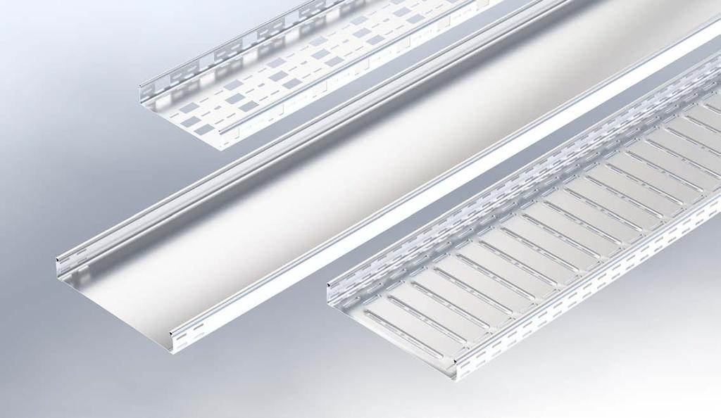
2 Cable trays serve the bridging of medium-size fitting distances. The support structures must be planned by engineering experts and observing the permissible torque of all screw connections. 1 Floor connector From 100 mm nominal width attach floor connector (VB) to the cable tray bottom. 2 Side connector Push the side connector (RGV) into the cable tray side rail, screw each side rail tight using a clamping screw (KLR), then push in the connecting tray and screw to the side connector (RGV). 3 Side connector Type R 35, RG 35, R 60, RG 60, and RI 60 cable trays are to be screwed using one clamping screw (KLR) per side rail. Type R 85, RG 85, R 110, and RG 110 cable trays are to be screwed with two clamping screws per side rail (top and bottom). 4 Snap-lock connectors Alternatively, the cable tray RG 60 can be latched on the inside below the head of the side rail using the snaplock connector (RGVS 60) without tools. Push the snaplock connector against the tray bottom by hand until a positive locking into place in the tray bottom occurs. 5 Fixed and floating bearings In case of extreme variations in temperature, a fixed and free bearing in the joint must be allowed for. Left view: Fixed bearing (with pre-stamped washer, FRSV+SEMS) Right view: floating bearing (with free washer FRSV+- SEMSS+US) and a clearance of 4 mm. 6 End plate In case of open support ends and a horizontal change in direction by < 30 open tray bottom. For cable tray ends or open changes in direction, push tray end plate (REB) into the bottom of the cable tray and screw together. 2


 and floor connector (VB) into cable tray and screw together in one place per side rail.")

.")
 and screw 14 Curve Push flexible cable tray curve (RVB) into cable trays and screw Insert the cable tray end plates at the")
 into the bottom of the cable tray")
3 7 Support distance to formed part end Applies to all formed parts or changes in direction or open ends: The maximum distance of 300 mm with regard to the formed part end and the support must be observed. 8 Horizontal curve Insert the horizontal curve (RB) and the floor connector (VB) into the cable tray and screw together in one place per side rail. For type R 85, RG 85, R 110 and RG 110 cable trays, screw in two places per side rail as described for RB. 9 Horizontal curve Insert connecting tray and floor connector (VB) into horizontal curve (RB) and screw together in one place per side rail. For type R 85, RG 85, R 110 and RG 110 cable trays, screw in two places per side rail as described for RB. 10 Junction Insert cable tray junction (RK) and floor connector (VB) into cable tray and screw together in one place per side rail. For type R 85, RG 85, R 110 and RG 110 cable trays, screw in two places per side rail as described for RB. 11 Horizontal change in direction For a horizontal change in direction without normed formed components, mitre the cable tray as required, deburr and cold-galvanise it. 12 Horizontal change in direction Bend both side connectors (RGV) to the necessary angle, insert into the side rails of the cable tray and screw together as described for RGV (see image 3). 13 Horizontal change in direction Place floor connector (VB) of corresponding length inside the cable tray bottom, push connecting cable tray into side connectors (RGV) and screw together as described for RGV (see image 3). 14 Curve Push flexible cable tray curve (RVB) into cable trays and screw together as described for RGV (see image 3). Insert the cable tray end plates at the ends of cable trays, push into the bottom of the cable trays and screw together as described for RGV (see image 6). 15 Vertical change in direction Vertical change in direction without formed component: Push tray end plate (REB) into the bottom of the cable tray and screw together as described for RGV (see image 3). Screw one RGV to each side rail with projection. 3
 into the bottom of the cable tray and screw together (see image 6).")
.")

.")
. 21 Extension angle Installation of tray extension angles (RAE).")
 into the cable trays and screw to the bottom in one place per side rail.")
4 16 Vertical change in direction Insert connecting cable tray into the side connectors (RGV) and screw together (see image 3). At the cable tray ends, push cable tray end plates (REB) into the bottom of the cable tray and screw together (see image 6). 17 Joint Push joint (RA) and floor connector (VB) into the cable tray and screw together as described for RGV (see image 3). For type R 85, RG 85, R 110 and RG 110 cable trays, screw in two places as described for RB (see image 8). 18 Extension joint Installation of extension joints manufactured on site (RAA). Cut out the side rail of the cable tray flush with the bottom in width B = the connecting cable tray width cm, deburr and cold-galvanise. 19 Extension joint Attach extension joint (RAA) and screw in one place per side rail. For type R 85, RG 85, R 110 and RG 110 cable trays screw together in two places as described for RB (see image 8). 20 Extension joint Insert connecting cable tray and floor connector (VB) into the extension joint (RAA) and screw together as described for RGV (see image 3). 21 Extension angle Installation of tray extension angles (RAE). Cut out the side rail of the cable tray flush to the bottom in width B = the extension cable tray width mm. 22 Extension angle Insert tray extension angles (RAE) into the cable trays and screw to the bottom in one place per side rail. Attach floor connector (VB). 23 Extension angle Trim extension trays by 60 mm per side rail, push onto the extension angles and screw together in one place per side rail. 24 Reduction Insert cable tray reduction (RR) and floor connector (VB) into the cable tray and screw together in one place per side rail. For type R 85, RG 85, R 110 and RG 110 cable trays screw together in two places as described for RB (see image 8). 4
.")
 into a z-shape and screw side connector (RGV) and tray end plate (RAB) 27 Reduction")
.")


 for electric components to the side rail of the cable tray in two")
 onto the cable tray and push against the side rail until a positive locking into")
5 25 Reduction Insert extension cable tray and floor connector (VB) into cable tray reduction (RR) and screw together as described for RGV (see image 3). 26 Reduction using a closing plate Cable tray reduction using a tray closing plate (RAB) and a side connector (RGV). Bend tray closing plate (RAB) into a z-shape and screw side connector (RGV) and tray end plate (RAB) as described for RGV (see image 3). 27 Reduction using a closing plate Insert extension cable tray and floor connector (VB) into the cable tray reduction (RAB) and screw together as described for RGV (see image 3). 28 Closing plate Closing of a cable tray using a tray closing plate (RAB). Bend tray closing plate into a u-shape and push into the cable tray. Screw together as described for RGV (see image 3). 29 End plate Mounting of the tray end plate for the protection of the inbound or outbound cables. Push tray end plate (REB) onto cable tray and screw to the bottom in two places if the width is at least 200 mm. 30 Barrier strip Screw barrier strip in three places (approx. 100 mm from both barrier strip ends as well as in the middle). 31 Assembly plate Screw the assembly plate (MP-RG) for electric components to the side rail of the cable tray in two places. 32 Cover Place the tray cover (RD) onto the cable tray and push against the side rail until a positive locking into place in the side rail occurs. For indoor use only! 33 Brackets Place the cover brackets (RDKL) sideways onto the tray cover (RD) and push against the cover bracket (RDKL) until a positive locking into place with the cable tray bottom occurs. For indoor use only! 6 pieces / 3 metres 5

 onto the cable tray (see image 32), then remove the separating foil of the adhesive")
 of the storm safety angle (RD-SW) on the inside through the cable tray.")
 to the cable tray (see image 32), place the storm safety angle (RD-SW) from the outside")
 (see image")
, should be placed on the cable tray curve, pushing against the side rail until a positive locking into place in the")
, are mounted with a turning bolt (RDR) as described for the tray cover (see image 34).")
6 34 Turning bolt The tray cover with a turning bolt (RDR) should be mounted as described for RD (see image 32). In addition, turn the turning bolt using a screwdriver until the slit in the screw head points lengthwise towards the cable tray. For indoor use only! 35 Adhesive metal strip Place the tray cover (RD) onto the cable tray (see image 32), then remove the separating foil of the adhesive metal strip (MKB) and wrap the strip around the cover and around the cable tray. For indoor use only! 36 Storm safety angle Lead the screw (KLR) of the storm safety angle (RD-SW) on the inside through the cable tray. Push the anti-loss washer (UVS M6) on the screw. 37 Storm safety angle Fasten the tray cover (RD) to the cable tray (see image 32), place the storm safety angle (RD-SW) from the outside onto the cover and screw using the screw nut SEMS M6. Suitable for outdoor use! 6 pieces / 3 metres 38 Curve cover As described for the cable tray covers (RD) (see image 32), the formed components, e.g. the curve cover (RBD), should be placed on the cable tray curve, pushing against the side rail until a positive locking into place in the side rail occurs. For indoor use only! 39 Curve cover The formed component covers with turning bolt, e.g. the tray curve cover (RDBR), are mounted with a turning bolt (RDR) as described for the tray cover (see image 34). 40 Storm safety angle Storm safety angles (RD-SW) for formed components covers are mounted as described for the tray cover (RD) (see image 38). In addition, the through holes should be made using an RDSW as a drilling template. RAA 2 pieces, RB 3 pieces and RA and RK 4 pieces 41 Cutting and sectioning work Perform cutting and sectioning work with greatest care and observe the occupational safety. 42 Galvanising All cutting and sectioning points must be galvanised with cold zinc paint (KZF) or cold zinc spray (KZS) by the customer after the deburring. 6
 Wear protection glasses Bolt diameter Strength")
 acc. VDI 2230 M6 4.6 5 4 M6 E 4.")

7 Legend Accessories FRSV 6x12 US 6x12 SEMS M6 SEMSS M6 SEM M6 KLR Symbols Screw tightening torques (recommended) Wear protection glasses Bolt diameter Strength category screw (DIN 267 part 3) Strength category nut (DIN 267 part 4) Screw tightening torque (Nm) acc. VDI 2230 M M6 E 4.6 A Wear ear protection Observe tightening torque for fasteners S F Sendzimir-hot-dip galvanised according to DIN EN Hot-dip galvanised according to DIN EN ISO 1461 E High-grade steel material No (V 2A) 7
8 Errors and technical modification subject to change. Reproduction as well as electronic duplication only with our written permission. With appearance of this print all preceding documents lose their validity. PUK Group PUK-MV KB-KR EN WEST x
Wide-span cable trays WPR Assembly instruction
 Wide-span cable trays are for bridging large fastening gaps. The fastening constructions must be planned by engineer and the use of side rail bearers on the brackets must be strictly kept. The permissible
Cable trays. Assembly instruction. Wide-span cable ladders WPL. Wide-span cable trays WPR. Support systems. Wire-mesh cable trays.
 Assembly Cable trays Assembling instruction Wide-span cable ladders WPL Assembly Instruction Wide-span cable trays WPR Assembly instruction Support systems Assembly instruction Wire-mesh cable trays Cable
Support systems Assembling instruction
 Support systems Support systems Light-duty Installation instruction for support systems of wire-mesh cable trays and cable trays attached directly to concrete. 1 Wall mounting with bracket KWLL To install
Ceiling mounting application, U support and bracket. Standard mounting of a cable tray with support, type US.., and suitable support bracket, type AW.
 Cable tray system RKS-Magic 35 and 60 mm Cable trays Type RKS-Magic Side height: 35, 60 mm Surface: FS Fittings: According to side heights Connecting parts According to side heights VDE testing According
Fixings & Fastenings. Bright Zinc Plated, Galvanised & Stainless Steel. Lockinex. ea i, ea u i
 Fixings & Fastenings Bright Zinc Plated, Galvanised & Stainless Steel Lockinex ea i, ea u i INTRODUCTION The Lockinex Range of Fixings & Fastenings are manufactured in Bright Zinc Plate, Hot dipped galvanised
ED1300/1300F SERIES CONCEALED VERTICAL ROD DEVICE INSTALLATION INSTRUCTIONS
 ED1300/1300F SERIES CONCEALED VERTICAL ROD DEVICE INSTALLATION INSTRUCTIONS Ver.2 1300 SERIES CONCEALED VERTICAL ROD DEVICE Top Strike Latch Screws Strike Screws Release Plunger Top Latch Plunger Screws
INSTALLATION INSTRUCTIONS
 INSTALLATION INSTRUCTIONS SPORTSMAN WINCH MOUNT GRILLE GUARD APPLICATION: 2016-2018 Toyota Tacoma PART NUMBER: 40-93885, 45-93880, 46-23885 ITEM QUANTITY DESCRIPTION TOOLS NEEDED 1 1 WINCH TRAY 15MM SOCKET
BSM, GSM & GSS. Joint Kit Instruction. (Modified for IMPACT) (NSF Certified) Curved Glass Fresh Meat Delicatessen and Seafood Merchandisers
 (NSF Certified) Curved Glass Fresh Meat Delicatessen and Seafood Merchandisers") BSM, GSM & GSS Joint Kit Instruction (Modified for IMPACT) (NSF Certified) Curved Glass Fresh Meat Delicatessen and Seafood Merchandisers February, 1999 JOINT ASSEMBLY PARTS LIST Item Quantity Description
BSM, GSM & GSS Joint Kit Instruction (Modified for IMPACT) (NSF Certified) Curved Glass Fresh Meat Delicatessen and Seafood Merchandisers February, 1999 JOINT ASSEMBLY PARTS LIST Item Quantity Description
INSTALLATION INSTRUCTIONS TRI-ROOF. energy for a better world
 energy for a better world INSTALLATION INSTRUCTIONS TRI-ROOF The flexible roof integration system Compatible for framed module types* Simple exchange of modules Replaces existing roofing Special profiles
Track Rack. * Track Racks are not lockable
 The Track Rack s unique staggered, sliding hook design creates the greatest parking efficiency while still providing easy access to any particular bike. When adding or removing a bike to the rack, simply
INSTALLING INVISIRAIL GLASS PANELS POST INFORMATION... 2 PRE-INSTALLATION... 2
 Contents POST INFORMATION... 2 PRE-INSTALLATION... 2 STEP A1: MEASURING FOR INVISIRAIL CUSTOM GLASS PANELS (skip if using Standard Sized Panels)... 2 STEP A2: GATHER ADDITIONAL TOOLS/SUPPLIES... 2 STEP
FABA. Installation Instructions. Conductor Bar System. Publication #FABA-03 3/1/04 Part Number: Copyright 2004 Electromotive Systems
 FABA Conductor Bar System Installation Instructions Publication #FABA-03 3/1/04 Part Number: 005-1062 Copyright 2004 Electromotive Systems 1S 100 Z Installation Instructions Contents: Basic Diagram - -
INSTALLATION INSTRUCTIONS VENETIAN 84" SLIDING SHOWER DOOR SYSTEM (180º INSTALLATION)
") INSTALLATION INSTRUCTIONS VENETIAN 84" SLIDING SHOWER DO SYSTEM (180º INSTALLATION) 28539 Industry Drive, Valencia, CA 91355 Toll Free Phone: (877) 728-3874 Toll Free Fax: (888) 440-9567 Phone: (661) 775-1675
INSTALLATION INSTRUCTIONS VENETIAN 84" SLIDING SHOWER DO SYSTEM (180º INSTALLATION) 28539 Industry Drive, Valencia, CA 91355 Toll Free Phone: (877) 728-3874 Toll Free Fax: (888) 440-9567 Phone: (661) 775-1675
Tel: +44 (0)
") 4 Lindapter s support fixing range offers a series of ideal solutions for all building services. This includes the suspension of HVAC equipment, pipe work, fire protection/sprinkler systems, suspended
4 Lindapter s support fixing range offers a series of ideal solutions for all building services. This includes the suspension of HVAC equipment, pipe work, fire protection/sprinkler systems, suspended
Simotec. 13.i
 Products: Framo 80 13.0 Products: Framo 80 13.1 Products: Structural Elements 100/120 13.2 Products: Pipe Shoes 13.3 Framo 80: Beam Section and Screw 13.4 Framo 80: Cantilever Bracket and End Support STA
Sport-Thieme Handball Goal, 3x2 m, Free-Standing or socketed
 Assembly instructions Art.-Nr.: 201 0915 203 4502 Sport-Thieme Handball Goal, 3x2 m, Free-Standing or socketed 0218214 2018 Sport-Thieme GmbH D-38367 Grasleben Germany sport-thieme.com info @sport-thieme.com
Index of keywords in the installation instructions for the chair lift type T80
 Index of keywords in the installation instructions for the chair lift type T80 Keyword Page Index of keywords. 1 Safety instructions and qualification. 2 Prerequisites.. 3 Transport and temporary storage...
We are Chalfant. We are OBO. We are One.
 RKS-Magic We are Chalfant. We are OBO. We are One. chalfant-obo.com Chalfant Manufacturing Company Chalfant Manufacturing has more than seventy years of experience designing and producing quality cable
v1.0 ASSEMBLY GUIDE Mia Wide Bookcase
 v1.0 ASSEMBLY GUIDE Mia Wide Bookcase Components Upon unpacking your bookcase from it s delivery box, you should have the pieces shown. Follow the steps on the next pages to assemble your new bookcase.
for HACA stationary fixed two rail ladders with / without safety cage
 Instructions for assembly and use for HACA stationary fixed two rail ladders with / without safety cage Please read before assembly! Caution: incorrect assembly can lead to a risk of death! Please contact
ClearSpan Twist-of-the-Wrist Assembly Instructions
 ClearSpan Twist-of-the-Wrist Assembly Instructions Curved-Wall for Roll-Up Side Flat-Wall for Curtain Application 2008 ClearSpan All Rights Reserved. Reproduction is prohibited without permission. Revision
Versatrac Bypass Door Units, Conventional and Top Track, 300 and 400 Series
 Versatrac Bypass Door Units, Conventional and Top Track, 300 and 400 Series TM Rough opening width (finished opening width plus 9/16") Notch for top track units (used as frame header) Rough opening height
CHICKEN COOP & CHICKEN RUN. Tools required for assembly (not included)
") CHICKEN COOP & CHICKEN RUN ASSEMBLY MANUAL SKU# 6839 Tools required for assembly (not included) Distributed by: TRACTOR SUPPLY COMPANY 0 VIRGINIA WAY, BRENTWOOD, TN 3707 For customer support, call: -888-376-960
CHICKEN COOP & CHICKEN RUN ASSEMBLY MANUAL SKU# 6839 Tools required for assembly (not included) Distributed by: TRACTOR SUPPLY COMPANY 0 VIRGINIA WAY, BRENTWOOD, TN 3707 For customer support, call: -888-376-960
Portofino Installation Guide
 vjul16 (for 17 or 24 mm Surface Wall Profiles) DO NOT ASSEMBLE WITHOUT FULLY READING THESE INSTRUCTIONS Page 2 Thank you for purchasing this Portofino shower enclosure. Please study these instructions
Deauville Installation Guide
 vjul16 (for 17 or 24 mm Surface Wall Profiles) DO NOT ASSEMBLE WITHOUT FULLY READING THESE INSTRUCTIONS Page 2 Thank you for purchasing this Deauville shower enclosure. Please study these instructions
Notes. Modifications and constructional corrections arising particularly from technological development excepted.
 Notes Our service staff and application en gineers will be pleased to offer you their assistance to answer your questions or to work out in cooperation with you specific solutions with the aid of our own
Sport-Thieme. Handball Goal. Assembly instruction. 3x2 m, Free-standing with Fixed Net Brackets
 Assembly instruction Sport-Thieme Handball Goal Cat.-no.: 115 0953 2392905 239 2918 113 6500 239 2400 239 2413 3x2 m, Free-standing with Fixed Net Brackets Thanks for choosing Sport-Thieme equipment! In
PFD-22 Top OHC Patch Fitting & PFD-10 Bottom Patch Fitting Installation Instructions
 Top OHC Patch Fitting & Bottom Patch Fitting Installation Instructions For Installation Assistance, Call 855.594.6989 www.assaabloyglass.us Tools Needed: Torque Wrench and Bit 5mm Allen Wrench 6 7 /16"
EZYMESH CABLE MESH EZYMESH. Cable Support Systems
 EZYMESH CABLE MESH EZYMESH 50 500 00 150 PRODUCT DETAILS EzyStrut EzyMesh provides premium performance in commercial and light industrial applications. Strong, versatile and easy to install EzyMesh is
ROBOT KR 350. Installation, Connection, Exchange. Ro/Me/03/ en. 1of 26
 ROBOT KR 350 Installation, Connection, Exchange 1of 26 e Copyright KUKA Roboter GmbH This documentation or excerpts therefrom may not be reproduced or disclosed to third parties without the express permission
Mounting systems for solar technology
 Mounting systems for solar technology ASSEMBLY INSTRUCTIONS Roof Fastener System CrossHook 2G GB Table of contents TABLE OF CONTENTS THE COMPANY SAFETY REGULATIONS MATERIALS REQUIRED TOOLS REQUIRED ASSEMBLY
APPENDIX FENCE GENERAL NOTES
 APPENDIX FENCE GENERAL NOTES 1. Fabric: 9 gage, 2" mesh, knuckle top and bottom, placed on the outside of posts, single fabric width for the entire height. 2. All fencing to be standard galvanized finish.
Swifts cable ladder ancillary items
 straight and curved dividers Straight dividers are used, along with curved dividers, to physically separate different types or groups of cable within one cable ladder run Straight dividers are supplied
Deauville Installation Guide
 vjul16 (for Recessed Wall Profiles) DO NOT ASSEMBLE WITHOUT FULLY READING THESE INSTRUCTIONS Page 2 Thank you for purchasing this Deauville shower enclosure. Please study these instructions carefully before
DOCK WEDGE - STANDARD
 DOCK WEDGE - STANDARD INSTALLATION INSTRUCTIONS WOOD HEADER READ ALL INSTRUCTIONS BEFORE INSTALLING SEAL. SUPER SEAL MFG. LTD. WILL NOT BE HELD RESPONSIBLE FOR IMPROPER INSTALLATION OF ANCHORING DEVICES,
Bollards, Column Guards, Corner Guards, Wheel Stops, Speed Humps & Fixings. Lockinex. ea i, ea u i
 Bollards, Column Guards, Corner Guards, Wheel Stops, Speed Humps & Fixings Lockinex ea i, ea u i INTRODUCTION Protecting Building Curtilage, Assets & Personnel the Lockinex range of Bollards & Guards are
Preparatory work. Core activity
 7714100 Installing crash bars + 77 14 500 Equipment trim-level variant: OA Crash bars NOTICE Engine protection bars cannot be installed in combination with left and right protectors for engine. Preparatory
Mounting a BalanceBox 400 to a brick wall
 Unpack the BalanceBox 400 and remove the Wall frame cover and its bag of screws. Slide the cover out at the top. NOTE: the cover is NOT included with the BalanceBox 400H LOCK SCREW HOLE MOBILE STAND MOUNTING
MEAstep Staircase construction kit
 M e t a l A p p l i c a t i o n s MEAstep Staircase construction kit A s s e m b l y i n s t r u c t i o n s Thank you...... for opting for a MEAstep staircase construction kit. This is a high-quality
CNC Router Parts PRO Machine Kit Cable Track Installation Instructions
 1 1 X CABLE TRACK TRAYS & BRACKETS The cable track on the side of the system is supported by a metal tray (or multiple trays for longer systems such as a PRO4896). These trays hang from brackets on the
A59 APD & A86 CPD 5'X 16' SW ALUMINUM PORTA-DOCK
 Page 1 of 5 PORTA-DOCK, INC. A59 APD & A86 CPD 5'X 16' SW ALUMINUM PORTA-DOCK *For Beige Decking Add the Letter B to model* Thank you for purchasing our product! *Please read these instructions and follow
Curium 19.4H Installation Instructions & Parts List
 Curium 19.4H Installation Instructions & Parts List Illustration Curium 19.4H Right Hand Page 1 of 21 30/06/2016 Revision 1.0 IMPORTANT This shower screen / enclosure must be installed by suitably qualified
HIT-30 ALUMINUM DOOR SERIES OWNERS MANUAL
 HIT-30 ALUMINUM DOOR SERIES OWNERS MANUAL INSTALL LOCKS LATCHES LEVERS / PADDLES INDICATORS STRIKES Every Installation Is A Self-Portrait Of The Person Who Did It! Autograph Your Work With Excellence!
Answer Power Beam and Boundary Screen
 Answer Power Beam and Boundary Screen 5/16 MAGNETIC 3/8 If you have a problem, question, or request, call your local dealer, or Steelcase Line 1 at 888.STEELCASE (888.783.3522) for immediate action by
INSTALLATION INSTRUCTIONS REPLACING EXISTING DEADBOLT ASSEMBLY
 INSTALLATION INSTRUCTIONS REPLACING EXISTING DEADBOLT ASSEMBLY A B C L M N D E F G O P Q H I J Tools provided in Amesbury installation kit: (A) door router fixture, (B) doorframe router fixture, (C) ½
Horizontal Cable Systems
 ALUMINUM RAILING INSTALLATION INSTRUCTIONS v2012 orizontal Cable Systems 1) Check Contents Of Packages: Verify that all parts have arrived and that they match the packing list. 1A) Coastal applications:
MOUNTING INSTRUCTIONS CONCRETE PURLIN BRACKET
 CONCRETE PURLIN BRACKET VERSION MARCH 2015 GENERAL INSTRUCTIONS Safety: Systems may only be installed and operated by properly trained and technically suitable people (i.e. MCS accredited installers).
Installation manual. For setting in concrete/on base plates - Panel height 1830
 1 Aluminium fencing and drive-in gates Installation manual For setting in concrete/on base plates - Panel height 1830 Aluclos system components: U10 Connecting U-bracket 1900 mm CL18/CL18.XL Half-height
Portofino Case2 Installation Guide
 Portofino Case2 Installation Guide vjun16 (for 17 or 24 mm Surface Wall Profile) DO NOT ASSEMBLE WITHOUT FULLY READING THESE INSTRUCTIONS Page 2 Thank you for purchasing this Portofino Case 2 shower enclosure.
ICU TRACKLESS SLIDING DOOR
 Interior View 0 Installation Instructions Tools Required: Screwdrivers Small Straight (Flat Blade) - for Terminal Block wiring # Phillips (Crosspoint) - for various #8, #0, and #4 screws Wrenches / Sockets
Front axle components, overview
 j a t Front axle components, overview 40-1 General Information Load bearing components and parts of the suspension must not be welded or straightened. Vehicles without drive axle must not be moved, or
Heavy duty profiles. Heavy loads with maximum stability. Profile general overview... p Heavy duty profiles... S Load data... p.
 Heavy loads with maximum stability Profile general overview... p. 366 Heavy duty profiles... S. 368 Load data... p. 372 Connection techniques... p. 374 Accessories... p. 384 Heavy duty profiles 365 Heavy
Assembly Instructions 10 X 10 Aluminum Roof Support
 Assembly Instructions 10 X 10 Aluminum Roof Support Aluminum Roof Support Bolt Package 16-5/16 X 2 ¼ SS Bolt 24-5/16 X 1 SS Bolt 40-5/16 SS Nylon Lock Nuts 16-5/16 SS Flat Washers 28-4 ½ Wood Screws 36-1
 800-753-9688 sales@novadisplay.com www.novadisplay.com 6.0mm Rod Fixings Components 6mm Basic Rod Fixings RAS TOP/BOTTOM FIXINGS FOR ROD - Includes Spring Tensioner, top/ceiling and bottom/floor fixings
Assembly Instructions 10 X 10 Aluminum Frame Building
 Assembly Instructions 10 X 10 Aluminum Frame Building 27 97 9 8 47 36 74 52 10 10 X 10 Square Building W/ Dome Includes: The Steel Entry Door with a Dead Bolt Lock assembly and Aluminum Door Frame. Metal
Sliding Door Kit
 YOU MUST READ THIS DOCUMENT BEFORE YOU BEGIN TO ASSEMBLE THE DOOR KIT. Thank you for purchasing this GrowSpan door kit. When properly assembled and maintained, this product will provide years of reliable
ASSEMBLY GUIDE. Mia Narrow Bookcase
 ASSEMBLY GUIDE Mia Narrow Bookcase Components: Upon unpacking your bookcase from it s delivery box, you should have the pieces shown. Follow the steps on the next pages to assemble your new bookcase. Step
TOOLS REQUIRED Metal Wood Wood and Metal Screws. #16 Drill #12-24 Tap. 1/8 Drill
 DEVICES COVERED IN THIS DOCUMENT: 4700S Surface Vertical Rod Device 4700SF Fire Exit Surface Vertical Rod Device TOOLS REQUIRED Metal Wood Wood and Metal Screws Sex Bolts #7 Drill ¼ -20 Tap #16 Drill #12-24
CABLE TRAY SYSTEM 136
 CABLE TRAY SYSTEM 136 137 WIRE MESH TRAY SYSTEM 138 139 WIRE MESH TRAY SYSTEM 140 141 WIRE MESH TRAY SYSTEM Wire Mesh Tray width B thickness (t) mm/inch mm/inch mm/inch V GR 35.100 35/1,4 100/3,9 3,5 V
Mounting systems for solar technology
 Mounting systems for solar technology ASSEMBLY INSTRUCTIONS Crosshook 3S CrossHook 4S GB Table of contents TABLE OF CONTENTS THE COMPANY SAFETY REGULATIONS MATERIALS REQUIRED TOOLS REQUIRED ASSEMBLY 2
Assembly Instructions
 Unite Panel System Hinge Door July 2016 #12 x / slotted hex washer head bolt Figure 1 threshold bracket frame Detail F threshold bracket threshold bracket (installed) #12 x / slotted hex washer head bolt
Prepare Base Assembly. (If pump is pre-assembled on base, go to step#8.)
") F L Instructions Maxim 3000 Turbo Flush Installation INTRODUCTION Satellite portable restrooms and accessories must be assembled according to approved assembly procedures. Avoid variations in assembly
F L Instructions Maxim 3000 Turbo Flush Installation INTRODUCTION Satellite portable restrooms and accessories must be assembled according to approved assembly procedures. Avoid variations in assembly
SIGNATURE FRONT BUMPER INSTALL
 SIGNATURE FRONT BUMPER INSTALL JL **PLEASE READ THROUGH THE INSTRUCTIONS BEFORE BEGINNING ANY PART OF THE INSTALLATION PROCESS** 1. You can now remove the trim strip (2 vertical clips, 4 horizontal, 2
B A T H R O O M G L A S S
 mistley B A T H R O O M G L A S S vaug16 Page 2 Thank you for purchasing this Trinity shower screen. Please study these instructions carefully before assembly and installation and check all supplied parts
NX8 SERIES 6-1/4 HANDRAIL W/ VINYL HANDGRIP
 6-1/4 HANDRAIL W/ VINYL HANDGRIP TYPICAL ASSEMBLY 5 2 BUTT JOINT 12 10 9 1 8 11 6 3 7 4 BUTT JOINT COMPONENT LIST 1 LEFT RETURN 7 UPPER IMPACT ABSORBER 2 RIGHT RETURN 8 LOWER IMPACT ABSORBER 3 OUTSIDE
Installation Instructions - Model V4JSD 1
 Installation Instructions - Model V4JSD 1 Support Assemblies: Parts list: (Note see enclosed cut sheet for quantities and dimensional information) A vertical structural member (1 ½ x 1 ½ modular frame)
EDGE2 DUAL MONITOR ARM
 EDGE2 DUAL MONITOR ARM EDGE2 Rev A 2/17 Model EDGE2-SLV Model EDGE2-BLK Model EDGE2-WHT ASSEMBLY AND ADJUSTMENT EDGE2 DUAL MONITOR ARM PARTS AND TOOLS PLEASE REVIEW these instructions before beginning
Assembly Instructions: Bencher Skylark
 Assembly Instructions: Bencher Skylark Tools Required: Pop Rivet Tool Tape Measure Hex Wrenches Screwdriver Several Disposable Rags Two Saw Horses Several boxes or bowls to hold fasteners and small parts
TZ-RD-1740 Rotary Dipole Instruction Manual
 TZ-RD-1740 17/40m Rotary Dipole Instruction Manual The TZ-RD-1740 is a loaded dipole antenna for the 40m band and a full size rotary dipole for the 17m band. The antenna uses an aluminium radiating section
H HD Adult Wheelchair Swing Frame & Hangers(perm) IMPORTANT
 IMPORTANT") Page 1 IMPORTANT PLEASE READ THESE INSTRUCTIONS BEFORE COMMENCING ASSEMBLY. All equipment must be installed in accordance with these instructions. Check your shipment against Bill of Lading and Parts list.
Page 1 IMPORTANT PLEASE READ THESE INSTRUCTIONS BEFORE COMMENCING ASSEMBLY. All equipment must be installed in accordance with these instructions. Check your shipment against Bill of Lading and Parts list.
DYNABOLT PLUS ANCHORS DYNABOLT PLUS. Anchor Details. Installation Ramset Regions. Site Map. Home Page. Performance. Next Page. Date of Issue: 9/98
 Date of Issue: 9/9 Dynabolt Plus is a general purpose all steel medium duty through fixing for masonry and concrete. For fixing to Concrete, solid and hollow brick, masonry, natural stone. Surface Finish
Opus Base Unit Assembly
 Opus Base Unit Assembly 5/16" NOTE: All cam locks need to be rechecked to confirm they are tight before installation. Gaps could result if not completely tightened and effect assembly. 2 Foot Scrap Board
FS Uno mounting instructions. 2 Pile driving (Ramming) 5. 6 Components list Torque specifications 15
 5. 6 Components list Torque specifications 15") FS Uno System Mounting instructions CONTTS Page 1 General - Safety, planning and tools 2 2 Pile driving (Ramming) 5 3 Rack overview - Components and fasteners 6 4 Mounting of the individual assembly groups
FS Uno System Mounting instructions CONTTS Page 1 General - Safety, planning and tools 2 2 Pile driving (Ramming) 5 3 Rack overview - Components and fasteners 6 4 Mounting of the individual assembly groups
Pickup Box Utility Rack Package Installation (Instruction ID: )
") 017 Chevrolet Colorado Pickup - WD (VIN S) Canyon, Colorado Accessory Installation Manual N America Document ID: 3966961 Pickup Box Utility Rack Package Installation (Instruction ID:3144879) Installation
017 Chevrolet Colorado Pickup - WD (VIN S) Canyon, Colorado Accessory Installation Manual N America Document ID: 3966961 Pickup Box Utility Rack Package Installation (Instruction ID:3144879) Installation
Factory Assistance: Phone: Fax: Page 1
 CABLE RUNWAY ACCESSORIES Radius Drop / Stringer Drop Provides 3 bend radius Radius drop fits 6, 12 and 18 runway made from 1-1/2 x 3/8 tubing Steel construction Includes (3) cable spools, (1) bolt, (1)
Installation and Assembly - Universal Articulating Swivel Double-Arm for 42" - 60" Plasma Screens
 Installation and Assembly - Universal Articulating Swivel Double-Arm for 42" - 60" Plasma Screens Models: PLAV 70-UNL, PLAV 70-UNL-S PLAV 70-UNLP, PLAV 70-UNLP-S R This product is UL Listed. It must be
Low Headroom Rear Mount TorqueMaster
 Low Headroom Rear Mount Supplemental Instruction Insert This supplemental installation instruction is to be used as a supplement to the main Installation Instruction and Owner s Manual provided with the
C70 Window Roller Repair Taken from: Heres the problem:
 C70 Window Roller Repair Taken from: http://www.volvospeed.com/vs_forum/topic/115086-how-to-c70-window-rollers-permanent-fix/ Heres the problem: This happened to two separate window assemblys on my c70
Pocket Door Kit PD1 / PD2 Installation Instructions. Kit Contents.
 Pocket Door Kit PD1 / PD2 Installation Instructions Kit Contents. 1, Create Rough Opening In Stud Wall Construct rough opening ensuring all sides are square and level. Rough opening should be; Height =
INSTALLATION INSTRUCTION RRU DOUBLE LIGHT POLE MOUNT
 INSTALLATION INSTRUCTION RRU Double Light Pole Mount for installation of two RRU units on mast, towers or other vertical structures. CUE DEE YOUR INNOVATIVE PARTNER 1 CONTENTS 1. PRODUCT COVERED IN THIS
Linear Motion and Assembly Technologies Aluminum Framing /07. Die-Cast Foundation Brackets 3-10 & 3-11
 -0 Linear Motion and ssembly Technologies luminum Framing 91 500 1 /07 Section : Profile onnectors Overview One of the greatest strengths of the osch Rexroth structural aluminum framing system is the wide
PROPELLER SHAFT PR 3 COMPONENTS
 PR3 COMPONENTS PR4 REMOVAL OF 1. DISCONNECT FRONT (a) Place the matchmarks on the both flanges. (b) Remove the four bolts, washers and nuts. (c) Pull the yoke from the transfer. (d) Insert SST in the transfer
Spiderbeam Balun Construction Guide
 BALUN CONSTRUCTION GUIDE Ver. 1.0 1 The components of the Balun Kit are in a plastic bag. Most of the components are inside the plastic case of the balun. The aluminum U-profile and the RG-142 Teflon Coax
Single-point fixing serie S32/35
 MNET Single-point fixing Single-point fixing serie S2/ The basic component within the MNET system is the single-point fixing a basic rather than cylindrical bore in the glass, has a tapered countersunk
ASSEMBLY AND ADJUSTMENT
 EDGE MONITOR ARM EDGE Rev A 2/17 Model EDGE-SLV Model EDGE-BLK Model EDGE-WHT ASSEMBLY AND ADJUSTMENT EDGE MONITOR ARM PARTS AND TOOLS PLEASE REVIEW these instructions before beginning the assembly and
Barofor Round System (polyester coated) Panels, Posts, Accessories
 Panels, Posts, Accessories") 1 Scope This Technical Data Sheet specifies the requirements for the Barofor Round System. The complete system exists of: Panels Posts Accessories such as fixation system and posts caps. Panels and posts
1 Scope This Technical Data Sheet specifies the requirements for the Barofor Round System. The complete system exists of: Panels Posts Accessories such as fixation system and posts caps. Panels and posts
TrendWall Floor-To-Ceiling Panels Installation Instruction
 TrendWall Floor-To-Ceiling Panels Installation Instruction TrendWall Components Covered by this Instruction: Crown (and accessories) Floor Plate Solid Panel Filler Panel Wall Channel Door Section Pilaster
ESA-300 Full Breakout
 Interior View 0 Installation Instructions For use with ESA II Controler DORMA AUTOMATICS, Inc. 94 Sherwood Drive Toll-Free: 877-67-6 DL844-00 Lake Bluff, IL 60044 Fax: 877-4-7999 Rev. /07 Tools Required:
Panel & Shelf Identification
 4 to 8 Aromatic Cedar Closet Model # 801 1 PLEASE READ INSTALLATION INSTRUCTIONS BEFORE ASSEMBLING Rev. C IF YOU ARE MISSING PARTS OR HAVE QUESTIONS PLEASE CONTACT: customerservice@cedargreen.net Tools
MX8 SERIES 6-1/4 HANDRAIL W/ VINYL HANDGRIP
 6-1/4 HANDRAIL W/ VINYL HANDGRIP TYPICAL ASSEMBLY 5 2 BUTT JOINT 12 10 9 1 8 11 6 3 7 4 BUTT JOINT COMPONENT LIST 1 LEFT RETURN 7 UPPER IMPACT ABSORBER 2 RIGHT RETURN 8 LOWER IMPACT ABSORBER 3 OUTSIDE
CABLE TRAY SYSTEM 248
 CALE TRAY SYSTEM 248 249 CALE LADDER SYSTEM 250 251 CALE LADDER SYSTEM 252 253 CALE LADDER SYSTEM Cable Ladder distance between rungs: 300 mm thickness (t) delivery length m S KL 60.203 60/2,3 200/7,8
Sliding Door Kit
 YOU MUST READ THIS DOCUMENT BEFORE YOU BEGIN TO ASSEMBLE THE DOOR KIT. Thank you for purchasing this GrowSpan door kit. When properly assembled and maintained, this product will provide years of reliable
System FS Duo Mounting Instruction. 1 General 2. 2 Pile driving 3. 3 Mounting the individual assembly groups 4. 4 Torque specifications 7
 System FS Duo Mounting instructions CONTENTS Page 1 General 2 2 Pile driving 3 3 Mounting the individual assembly groups 4 4 Torque specifications 7 5 Module mounting 8 6 Tolerances 8 1 / 8 1 General 1.1
Fig. 2 DORMA-Glas Stand/Issue 02/03 Seite/Page 1/7
 FSW Installation instructions Track rail 75 x 72 mm 1. Ceiling substructure and installation of the track rail (Fig. 1): The track rail must be bolted over its entire length (including the stacking track
Installation and Assembly: Flat Video Wall Mount For 40" to 65" Flat Panel Displays
 Installation and Assembly: Flat Video Wall Mount For 40" to 65" Flat Panel Displays Model: DS-VW665 Maximum Load Capacity: 125 lb (57 kg) 1 of 11 ISSUED: 03-22-12 SHEET #: 125-9288-4 06-25-13 NOTE: Read
The series terminals are state of the art based on technical enhancements, changes in power engineering, their applications and properties.
 w TERMINALS SERIES IK6 GENERAL INFORMATION The series terminals are state of the art based on technical enhancements, changes in power engineering, their applications and properties. 402 Since series terminals
Instruction Sheet For: SCM-2
 Instruction Sheet For: SCM-2 For more information, please contact us at: 345 Log Canoe Circle, Stevensville, Maryland 2666 Toll Free: 877.28.269 Phone: 40.643.6390 Fax: 40.643.665 www.videomount.com 27
Installation and Assembly - Universal Articulating Swivel Double-Arm for 42" - 60" Plasma Screens
 Installation and Assembly - Universal Articulating Swivel Double-Arm for 42" - 60" Plasma Screens Models: PLAV 70-UNL, PLAV 70-UNL-S PLAV 70-UNLP, PLAV 70-UNLP-S R This product is UL Listed. It must be
GlideRite Retractable Cover System For Hot Spot Spas (SE & SLX only)
") List of Contents Quantity Description 12 #10 x 1 ½ Flat Head Phillips Screw (see pg. 2) 2 #10 x ½ Pan Head Phillips Screw (see pg. 2) 8 ¼ x 2 ½ Lag Bolt (see pg. 2) 7 ¼ 20 x 5 / 8 Hex Head Bolt (see pg.
List of Contents Quantity Description 12 #10 x 1 ½ Flat Head Phillips Screw (see pg. 2) 2 #10 x ½ Pan Head Phillips Screw (see pg. 2) 8 ¼ x 2 ½ Lag Bolt (see pg. 2) 7 ¼ 20 x 5 / 8 Hex Head Bolt (see pg.
INSIDE PANEL NOT SHOWN TO DETAIL ANCHORING SYSTEM
 SIX INCH ALPHA MODULE INSTALLATION KEWAUNEE SCIENTIFIC CORPORATION SIX INCH ALPHA MODULE ANCHORING SYSTEM After Alpha module has been set in desired location. Adjust the four adjustment bolts until the