GEOMETRY Unraveled. A Technology Update on Twin-screw Extrusion by Dr. Babu Padmanabhan Ph.D
|
|
|
- Carol Potter
- 6 years ago
- Views:
Transcription


1 CD Do Di
2

3 Do CD Di GEOMETRY Unraveled A Technology Update on Twin-screw Extrusion by Dr. Babu Padmanabhan Ph.D
4 Introduction Co-rotating Twin-screw extruders are versatile devices that allow work to be done efficiently on plastic materials. The work done generally raises the temperature of the material being processed, resulting in a partial or complete fusion of the mixture, an increase in the uniformity of the composition, a chemical union between the components constituting the mixture and finally a reduction in the size of particles in that mixture. Work done on the material is the result of application of shear forces, extensional forces that cause elongation or stretching of material, compressive forces that results in pressure build-up and squeezing of the material and bending forces that causes fibers and layers to fold and interact. These forces occur in three dimensional space inside the extruder defined by the Axial Plane, Longitudinal plane for each screw and several Radial planes. Flow of material between elements in different radial planes creates lateral shear in the material. In general, radial and lateral shear rates are 10 to 100 times greater in magnitude compared to axial or longitudinal shear stress. Radial and Lateral shear are not experienced uniformly by every macro-molecule or particle in the mix leading to the most common difficulty in plastics processing. Improvements in the working of the extruder always lead to creating circumstances for uniformity in the radial and lateral shear rates, extensional flow patterns and frequent re-orientation. Any effort to fully understand the working of a twin-screw extruder has to begin with a study of the geometry of the twin-screw equipment. In 1978, Booy [1] conducted such a study based on about 20 years of work carried out in the field. Since then, important innovations such as Eccentric Elements and Fractional Lobed Elements have revolutionized the effectiveness of the equipment. This paper attempts to provide a most recent update on the geometry of the elements, the crucial part of the processing section in a co-rotating twin-screw extruder. Technology Update on Twin-screw Extrusion: Geometry Unraveled -2-
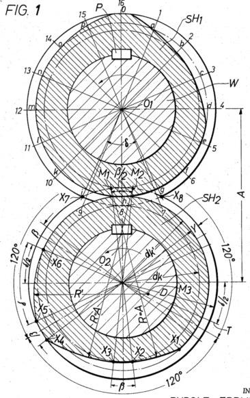
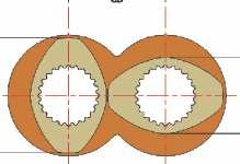
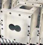
5 Known Element Geometry The essential requirement of a closely intermeshing co-rotating twin-screw extruder element profile is the ability for one screw to wipe the 1 other and vice-versa. The Barrel Diameter (D b) and Center-distance (Cd) are the fundamental parameters used to define the geometry of the element. The conveying screws, kneading blocks, mixing elements and other elements are formed by the helical or linear transformation of the cross-sectional geometry of the profile. Figure 1: Cross-section of a Barrel with Element 1 Barrels are also referred as Cylinders or Housing The relationship between the screw profile parameters and the barrel parameters can be written in the following manner Barrel Diameter (D ) = Outer Diameter (D ) + 2 * Barrel-Screw Clearance (δ ) b o b Center Distance (Cd) = {Outer Diameter (D ) + Minor Diameter (D )}/2 + Screw-Screw Clearance (δ ) o i s The ratio of the Outer Diameter (D ) and the Minor Diameter (D ) is called the Ratio of Diameters (Rd) or the D /D ratio. o i o i Ratio of Diameters (Rd) <Rd < 1 Number of Lobes (Nl) <Rd < ,2,3, <Rd < ,2, <Rd < ,2 For a ratio of 1.50, it can be seen from this table that it is not possible to design a tri-lobed (three lobes) profile. Presently, most twin- 2 screw extruders are designed with ratio of 1.50 and above. Therefore, the bi-lobed (two lobes) geometry is the most commonly used. -3-
6 Figure 2: Outer Profile Parameters The Tip Angle (Te) can be expressed in the following equation -1 Tip Angle (Te) (in Radians) = (Pi) / Number of Lobes (NI) 2 * Cos (Fr/D o) Where Flank Radius (Fr) = (D o + D i) / 2 The Tip Angle obtained using the above equation is called Erdmenger or Constant-clearance Tip Angle (Te). For a given Ratio of Diameters (Rd), a twin-screw geometry with a larger Tip Angle than Erdmenger Tip Angle (Te) is not possible. 2 Single lobed profile is possible for any ratio. However, higher number of lobes results in increased free volume. When the Number of lobes (NI) is an odd number (1 or 3), then the two profiles form a conjugate pair in the same orientation or at an angle of 0 degrees with respect to the other. When the Number of lobes (2 or 4) is an even number the two profiles form a conjugate pair at a defined angle (90 degrees or 45 degrees) respectively. Figure 3: Bi-lobes forming Conjugate pair (with constant clearance) at 90 degrees relative to the other. -4-
7 The clearances play an important role in ensuring that the screw profile can center itself inside the barrel at the time of processing. Smaller or larger clearances can be used while processing different type of material. Typical Clearance between the Screw and the Barrel (δ b) = 0.25mm Typical Clearance between the two Screws (δ s) = 0.5mm For a constant clearance profile δ s = δ s1 = δ s2 ; clearances at all rotational position is constant. Due to certain processing requirements (or manufacturing convenience), the Actual Tip Angle (Ta) used may be smaller than the Erdmenger Tip Angle (Te). This modification changes the clearance when the profile rotates to a new position. Figure 4: Bi-lobes forming Conjugate pair with varying clearances Figure 5: Bi-lobed Single-arc profile forming a Conjugate pair It is possible to design the geometry using a single arc. Such geometry result in a varying clearance. Interestingly, the highest clearance although at the 45 degree position is not at the tip but a little below it. This results in a reduction of wear at the tip. -5-
 along the axis of rotation.")

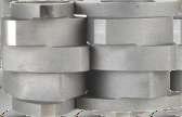
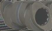
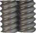
8 Figure 6: Conveying Screw Element The screw element is obtained by a helical transformation. This transformation is defined by a continuous rotation with a forward movement (translation) along the axis of rotation. While looking at the screw element such that the rotation is in a clockwise direction, if the translation is downward then the screw is called a Right Handed Screw element. For a clockwise rotation, if the translation is upward, then the screw is called a Left Handed Screw element. The Lead of the screw element is defined as the translation length for a complete turn (360 degrees). The important Conveying screw element parameters are therefore the Lead (Ld), Hand (Hd) and Length (Ln). When very long lead elements where the lead is 10D or more are used in right and left lead combination, the formation looks similar to a Farrel type continuous mixer element. Figure 7: Kneading Element -6-
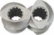
9 The Kneading Elements are formed by translation of the profile by a distance called the Segment Thickness. The next segment is started at a new twist angle and taken through another translation. There is usually an overlap between the adjacent segments resulting in a clearance between the segments. The important Kneading Element parameters are the Length (Ln), Twist Angle (TwA), Hand (Hd) and Segment Thickness (Sn) and Clearances (Cn). Eccentric Element Geometry In 1989, Häring et al.[3] introduced a new concept in Element Design. They discovered that the profile can be designed for a smaller diameter ratio (Rd) for a given same center distance and moved eccentric to the shaft. This enables tri-lobed profile to be designed for diameter ratios as high as 1.5 or more. Figure 8: 3 Lobed Eccentric elements with Do/Di = 1. It may be noted that concentric tri-lobed elements cannot be used in a bi-lobed extruder with Do/Di greater than Eccentric lobes used as in the form of conveying screws are sometimes referred to as camel-back elements. Otherwise, eccentric lobed elements are used as kneading blocks. An advantage in using eccentric lobed elements is that it reduces some of the non-uniformity in lateral shear. It all leads to more frequent reorientation causing improvement in mixing action. Fractional Lobes In 1963, Erdmenger [6] wrote in a relatively less known Patent document, one disadvantage that was hitherto encountered in apparatuses of this type was that it was only possible to vary the dimensions lying in the axial direction but not the dimension lying transversely to the axis, e.g. the thickness of the layer of material used, which often has an important effect on the transfer of heat or the transfer of material or the course of the reaction. Tri-lobed profile was modified in a new manner in this invention a predecessor to the Fractional lobed elements. Erdmenger calls this as the most important alteration in practice. This design is an instance of fractional lobed element but only half of it. It should be designated under the fractional lobe naming convention as the B/2. -7-
![Sakagami [4] recognized that Element profile can be created by applying different Diameter Ratios from lobe to lobe.](/docs-images/72/67032259/images/10-0.jpg "In the case of the example shown below [R#], one of the bi-lobe has the standard ratio, while the other one has a decreased ratio resulting in an increased Inner Diameter (Di) and decreased Outer")
10 Sakagami [4] recognized that Element profile can be created by applying different Diameter Ratios from lobe to lobe. In the case of the example shown below [R#], one of the bi-lobe has the standard ratio, while the other one has a decreased ratio resulting in an increased Inner Diameter (Di) and decreased Outer Diameter (Do) which is clearly evident in the figure. Sakagami calls this SMAP screw design and believes that kneading blocks can be completely eliminated for melting with this design. A screw elements formed with this design resembles a barrier screw in a single screw extruder. Figure 9: Erdmenger s half a Fractional Lobed Element Design Figure 10: Sakagami Modification resulting in a complete fractional lobed element
11 Fractional Lobe Geometry takes this approach to any number of lobes with a unified concept. Fractional lobes are formed using two different Integer lobes together. At this time, there is only one condition to be met that the ratio of the two such lobes should also be an integer. Therefore a Single flight profile (Uni-lobe) and a Bi-lobe can form fractional lobes such as 1.2.xx where xx can be number from 01 to 99. These numbers 01 to 99 will define whether the fractional lobe will look more like a single flight element or a bi-lobed element. A Single flight profile and a Four-lobe profile can form fractional lobes such as etc. 1 and 3 lobes can also be combined as well as 2 and 4 lobed. These combinations result in an infinite series of profiles to chose from offering enormous capability in the hands of extruder users and designers. Figure 11a: Fractional Lobed Geometry Figure 11b: Fractional Lobed Geometry Figure 11c: Fractional Lobed Geometry a Figure 12: Fractional Lobed Geometry b -9-


12 Figure 13: Mathematical Principle for generation Fractional Lobes Other Modifications SK modification Figure 14: Kneading Disks formed for Fractional Lobes Figure 15: Under-cut Element -10-


 slippery and other difficult to convey materials at high rates compared to any of the available element geometry.")
13 This element is used to enhance the free volume during intake or venting. The axial cross-section is modified to become perpendicular to the axis with a small radius (Rd) at the minor diameter. It is important to note these elements are only partially wiping and not fully wiping the other element. These elements are generally used in the intake zone before the solid material forms a melt. However, they can be used in any zone that is partially filled after melting. This is because the flow of material can itself create the effect of cleaning. Importantly, wiping profiles does not always clean, since cleaning action requires transfer of material forward during the act. If material is pushed backwards or in a radial direction, cleaning does not Occur. FV modification (Patent Pending) These are specially modified highly efficient conveying elements. The elements can convey (by ploughing into the material with a shovel like surface) slippery and other difficult to convey materials at high rates compared to any of the available element geometry. Figure 16: SFV element for Intake Zone Figure 17: TFV element for Side-feed Zone These elements have the ability to feed low bulk density material (such as a 50% Talc pre-mix) at an extremely high rate (around 2 to 4 times the capacity of a SK type element in starve feed mode). These elements are capable of turning a feed-limited extruder (as in the case of applications with low bulk density material) to that of a torque limited one (as in the case of most applications). The geometry has a special nature of improving the feed-rate at greater speeds unlike standard elements which tend to fluidize the material and a drop in feed-rate occurs at higher speeds. Several other modifications including screw mixing elements such as SMEs, ZMEs, TMEs have been left out from this discussion. These grooved modifications sacrifice on self-cleaning either by wiping or due to natural flow and were a quick-fix remedy rather than a lasting solution to certain distributive mixing needs. In general, these elements are slowly getting replaced with more scientifically designed elements. -11-
14 Summary Co-rotating twin-screw extruders are versatile mixing devices that can contribute to the development of new plastic materials. This paper attempts to provide the latest development in designing the heart of this equipment. Already, a number of fractional lobe geometry has been used to form various elements. These have resulted in improving the melting and mixing characteristics of the extruder. Concerted efforts are being made to carryout further developmental activity to enable the plastics industry to realize complete benefit from this concept. Ultimately the task of an extruder is to carryout the right amount of work of the right kind (shearing, stretching, folding or squeezing) at the right place for the right amount of time. Plastics processing has been a technology s domain however still an art form. With newer elements and more detailed understanding, it would soon enter into a realm of exact science. References 1. M. L. Booy, Polymer Engineering and Science, Sep R. Erdmenger, U.S. Patent 2,670,188 Feb. 23, E. Häring et al U. S. Patent 4,824, 256, Apr 25, M. Sakagami, U. S. Patent 4,300, 839, Nov 17, J. Blach, DE , May 26, R. Erdmenger, U. S. Patent 3,254,367 Jun 7, Padmanabhan et al, Effect of Element Geometry, ANTEC Visit


15

16 This booklet is brought to you by : For more information please contact : INDIA STEER ENGINEERING Pvt Ltd., 290, 4th Main, 4th Phase, Peenya Industrial Area, Bangalore , India. Tel: /10 Fax: info@steerworld.com rsiyengar@steerworld.com Web: USA STEER AMERICA LLC 116 Eva Drive, Gibsonville, NC Tel: Fax: w.stagner@steerworld.com Web: JAPAN STEER JAPAN Fukui Building Room No.402, Higashiueno, Taito-ku, Tokyo, , Japan. Tel: Fax: info@steerjapan.com Web: EUROPE Extruder Experts GmbH & Co. KG Am Handwerkerzentrum 1 / Office B27, D Monschau-Imgenbroich, Germany. Tel: Fax: info@extruder-experts.com Web:
Troubleshooting Single-Screw Extrusion Top 10 List Mark A. Spalding The Dow Chemical Company, Midland, MI
 Troubleshooting Single-Screw Extrusion Top 10 List Mark A. Spalding The Dow Chemical Company, Midland, MI Gregory A. Campbell Castle Research, Jonesport, ME Goals Provide a list of practices and skills
Profile Extrusion. Extrusion. Extrusion PL ET 370. Extrusion Screw. Screw Terminology
 Profile PL ET 370 Modified S05 Screw Screw Terminology L/D - Ratio of Screw Length to Screw Diameter Compression Ratio - Ratio of the volume in the first flight to the volume in the last flight Mixing
Injection moulding BUDAPEST UNIVERSITY OF TECHNOLOGY AND ECONOMICS FACULTY OF MECHANICAL ENGINEERING DEPARTMENT OF POLYMER ENGINEERING
 B3 BUDAPEST UNIVERSITY OF TECHNOLOGY AND ECONOMICS FACULTY OF MECHANICAL ENGINEERING DEPARTMENT OF POLYMER ENGINEERING Injection moulding INJECTION MOULDING OF THERMOPLASTICS WWW.PT.BME.HU LOCATION OF
1/2/2016. Lecture Slides. Screws, Fasteners, and the Design of Nonpermanent Joints. Reasons for Non-permanent Fasteners
 Lecture Slides Screws, Fasteners, and the Design of Nonpermanent Joints Reasons for Non-permanent Fasteners Field assembly Disassembly Maintenance Adjustment 1 Introduction There are two distinct uses
Recommended Dimensional Guidelines for Single Screws
 The Society of the Plastics Industry s Machinery Component Manufacturers Division Recommended Dimensional Guidelines for Single Screws The following recommendations for single screws of injection molding
INNOVATIONS IN EXTRUDER FEED SECTIONS
 INNOVATIONS IN EXTRUDER FEED SECTIONS Keith Luker Randcastle Extrusion Systems, Inc. 74 Sand Park Road Cedar Grove, NJ Abstract: A single screw extruder has a hole in the barrel that serves to transfer
OUR GLOBAL AFTER SALE SERVICE NETWORK. Service-Hotline
 OUR GLOBAL AFTER SALE SERVICE NETWORK Service-Hotline +49 800 1000688 service@isog-technology.com Dortmund Stuttgart Ulm Nürnberg Berlin Passau Printed in the Federal Republic of Germany. Edition 201408/E/PDF/11.
Experimental Evaluation of Metal Composite Multi Bolt Radial Joint on Laminate Level, under uni Axial Tensile Loading
 RESEARCH ARTICLE OPEN ACCESS Experimental Evaluation of Metal Composite Multi Bolt Radial Joint on Laminate Level, under uni Axial Tensile Loading C Sharada Prabhakar *, P Rameshbabu** *Scientist, Advanced
Twin screw and barrel are the heart of extruders and play very crucial role in extruder.
 SHREE RADHEKRISHNA EXTRUSIONS PVT.LTD, a renewed engineering company has been Serving in the field of manufacturing screw & barrel for last more then 20 years. Radhekrishna Extrusions manufactures screw
CLAMPING TECHNOLOGY Individual special clamping tools
 CLAMPING TECHNOLOGY Individual special clamping tools 1 QUALITY SINCE 1958 Know-how, the highest quality and first class engineering. We see ourselves as a system supplier and offer our customers a full
Straight Bevel Gears on Phoenix Machines Using Coniflex Tools
 Straight Bevel Gears on Phoenix Machines Using Coniflex Tools Dr. Hermann J. Stadtfeld Vice President Bevel Gear Technology January 2007 The Gleason Works 1000 University Avenue P.O. Box 22970 Rochester,
Injection moulding BUDAPEST UNIVERSITY OF TECHNOLOGY AND ECONOMICS FACULTY OF MECHANICAL ENGINEERING DEPARTMENT OF POLYMER ENGINEERING
 B3 BUDAPEST UNIVERSITY OF TECHNOLOGY AND ECONOMICS FACULTY OF MECHANICAL ENGINEERING DEPARTMENT OF POLYMER ENGINEERING Injection moulding INJECTION MOULDING OF THERMOPLASTICS WWW.PT.BME.HU LOCATION OF
Table of Contents. Fundamentals of Screw Thread Technology Definitions and Terminology Gage Design Contacts...
 1 Distributed by: Gage Crib Worldwide Inc 6701 Old 28th St SE, Suite B Grand Rapids, MI 49546-6937 USA Phone: 001.616.954.6581 Web: www.gagecrib.com Table of Contents SECTION 1: Fundamentals of Screw Thread
MANUFACTURING TECHNOLOGY
 MANUFACTURING TECHNOLOGY UNIT II SHEET METAL FORMING PROCESSES Sheet Metal Introduction Sheet metal is a metal formed into thin and flat pieces. It is one of the fundamental forms used in metalworking,
DEVELOPMENT OF A NOVEL TOOL FOR SHEET METAL SPINNING OPERATION
 DEVELOPMENT OF A NOVEL TOOL FOR SHEET METAL SPINNING OPERATION Amit Patidar 1, B.A. Modi 2 Mechanical Engineering Department, Institute of Technology, Nirma University, Ahmedabad, India Abstract-- The
MN Modelling Objects and Creating Manufacturing Strategy
 Abstract This document and the accompanying files describe the process of modelling a bell housing jig using the 3D software Catia V5. The manufacturing process by which the bell housing would be created
Module 4 General Purpose Machine Tools. Version 2 ME, IIT Kharagpur
 Module 4 General urpose Machine Tools Lesson 24 Forces developing and acting in machine tools Instructional objectives At the end of this lesson, the students will be able to; (i) Identify the sources
MANUFACTURING TECHNOLOGY
 MANUFACTURING TECHNOLOGY UNIT II SHEET METAL FORMING PROCESSES Sheet metal Process in detail Cutting (Shearing) Operations Manufacturing Technology In this operation, the work piece is stressed beyond
INSTRUCTIONS FOR USE B2 FORM KNURLING TOOL
 INSTRUCTIONS FOR USE B2 FORM KNURLING TOOL Contents CONTENTS 1. General... 2 1.1 Introduction... 2 1.2 Tool Construction... 3 2. B2 Tools... 6 2.1 Technical Data... 6 2.2 Overview: Main components... 7
GE 101 Final Design Project:
 GE 101 Final Design Project: Clear Point Mechanical Pencil Presented and Submitted on: Monday May 8, 2009 Sarah Fullmer David Montiel Wonseok Oh Ryan Smith Table of Contents Table of Contents... ii List
INSTRUCTIONS FOR USE A1 & A2 KNURLING TOOLS
 INSTRUCTIONS FOR USE A1 & A2 KNURLING TOOLS Contents CONTENTS 1. General... 2 1.1 Introduction... 2 1.2 Tool Construction... 3 2. A1-Tools... 5 2.1 Technical Data... 5 2.2 Overview: Main Components...
Available online at ScienceDirect. Procedia Engineering 81 (2014 )
") Available online at www.sciencedirect.com ScienceDirect Procedia Engineering 81 (2014 ) 641 646 11th International Conference on Technology of Plasticity, ICTP 2014, 19-24 October 2014, Nagoya Congress
Available online at www.sciencedirect.com ScienceDirect Procedia Engineering 81 (2014 ) 641 646 11th International Conference on Technology of Plasticity, ICTP 2014, 19-24 October 2014, Nagoya Congress
Computer Numeric Control
 Computer Numeric Control TA202A 2017-18(2 nd ) Semester Prof. J. Ramkumar Department of Mechanical Engineering IIT Kanpur Computer Numeric Control A system in which actions are controlled by the direct
1. Enumerate the most commonly used engineering materials and state some important properties and their engineering applications.
 Code No: R05310305 Set No. 1 III B.Tech I Semester Regular Examinations, November 2008 DESIGN OF MACHINE MEMBERS-I ( Common to Mechanical Engineering and Production Engineering) Time: 3 hours Max Marks:
Copyright 2004 Society of Manufacturing Engineers. FUNDAMENTAL MANUFACTURING PROCESSES Extrusion Processes NARRATION (VO): NARRATION (VO):
: NARRATION (VO):") FUNDAMENTAL MANUFACTURING PROCESSES Extrusion Processes SCENE 1. EP43A, GRAPHIC: Plastic Extrusion white text centered on black SCENE 2. EP44A, peter carey narration EP44B, tape 890, 05:28:23-05:28:43
FUNDAMENTAL MANUFACTURING PROCESSES Extrusion Processes SCENE 1. EP43A, GRAPHIC: Plastic Extrusion white text centered on black SCENE 2. EP44A, peter carey narration EP44B, tape 890, 05:28:23-05:28:43
PELLETIZING EXTRUDER FEED SCREWS. Davis-Standard Feed Screws are Built to Perform Better. The Davis-Standard Advantage
 PELLETIZING EXTRUDER FEED SCREWS Davis-Standard Feed Screws are Built to Perform Better For decades, Davis-Standard has been recognized around the world as a leader in the design and manufacture of extrusion
Gear testing instruments VP with face stop. Measurement of the dimension between or over two balls
 Gear testing instruments VP with face stop Measurement of the dimension between or over two balls VP E 11 2013 Measuring with face stop VP gear testing instruments feature a face stop. Finding the reversal
Geometric Dimensioning and Tolerancing
 Geometric Dimensioning and Tolerancing (Known as GDT) What is GDT Helps ensure interchangeability of parts. Use is dictated by function and relationship of the part feature. It does not take the place
Hail University College of Engineering Department of Mechanical Engineering. Sheet-Metal Forming Processes and Equipment. Ch 16
 Hail University College of Engineering Department of Mechanical Engineering Sheet-Metal Forming Processes and Equipment Ch 16 Sheet-Metal Forming Products made of sheet metals are all around us. They include
NX 7.5. Table of Contents. Lesson 3 More Features
 NX 7.5 Lesson 3 More Features Pre-reqs/Technical Skills Basic computer use Completion of NX 7.5 Lessons 1&2 Expectations Read lesson material Implement steps in software while reading through lesson material
Design and Analysis of Press Tool Assembly
 Design and Analysis of Press Tool Assembly Raveendra M.Tech Student ABSTRACT Press working may be defined as a chip less manufacturing process by which various components are made from sheet metal. This
(51) Int. Cl."... B29B 748 Attorney, Agent, or Firm John G. Gil?illan, III; William
 Int. Cl.... B29B 748 Attorney, Agent, or Firm John G. Gil?illan, III; William") USOO611677OA United States Patent (19) 11 Patent Number: Kiani et al. (45) Date of Patent: Sep. 12, 2000 54 MIXING ELEMENT FORSCREW FOREIGN PATENT DOCUMENTS EXTRUDER O 330 308 A1 8/1989 European Pat. Off..
USOO611677OA United States Patent (19) 11 Patent Number: Kiani et al. (45) Date of Patent: Sep. 12, 2000 54 MIXING ELEMENT FORSCREW FOREIGN PATENT DOCUMENTS EXTRUDER O 330 308 A1 8/1989 European Pat. Off..
B rochure & Specifications
 B rochure & Specifications MEET THE HELICAL FORMER D e cember 2017 THE HELICAL FLIGHT FORMER PRODUCES TRUE HELICES FOR EARTH AUGERS, AUGER WINGS, SCREW FEEDERS, SCREW-PILES, HELICAL PIERS, SCREW CONVEYORS,
Screws. Introduction. 1. Nuts, bolts and screws used to clamp things together. Screws are used for two purposes:
 Screws Introduction Screws are used for two purposes: 1. To clamp things together. 2. To control motion. 1. Nuts, bolts and screws used to clamp things together. Nuts, bolts and screws that are used for
TAPS AND THREADING DIES
 872 TAPS AN THRAING IS TAPS AN THRAING IS General dimensions and tap markings given in the ASM/ANSI Standard B94.9-1987 for straight fluted taps, spiral pointed taps, spiral pointed only taps, spiral fluted
KRW bearing solutions for rotary tables
 KRW bearing solutions for rotary tables All data have been prepared with a great deal of care and checked for their accuracy. However, no liability can be assumed for any incorrect or incomplete data.
125 years of innovation. Cylindricity. Global Excellence in Metrology
 125 years of innovation Cylindricity Cylindricity Contents Introduction Instrument Requirements Reference Cylinders Cylindricity Parameters Measurement Techniques & Methods Measurement Errors & Effects
CH # 8. Two rectangular metal pieces, the aim is to join them
 CH # 8 Screws, Fasteners, and the Design of Non-permanent Joints Department of Mechanical Engineering King Saud University Two rectangular metal pieces, the aim is to join them How this can be done? Function
KRW bearing solutions for rotary tables
 KRW bearing solutions for rotary tables All data have been prepared with a great deal of care and checked for their accuracy. However, no liability can be assumed for any incorrect or incomplete data.
Lecture 15. Chapter 23 Machining Processes Used to Produce Round Shapes. Turning
 Lecture 15 Chapter 23 Machining Processes Used to Produce Round Shapes Turning Turning part is rotating while it is being machined Typically performed on a lathe Turning produces straight, conical, curved,
ROOP LAL Unit-6 Lathe (Turning) Mechanical Engineering Department
 Mechanical Engineering Department") Notes: Lathe (Turning) Basic Mechanical Engineering (Part B) 1 Introduction: In previous Lecture 2, we have seen that with the help of forging and casting processes, we can manufacture machine parts of
Notes: Lathe (Turning) Basic Mechanical Engineering (Part B) 1 Introduction: In previous Lecture 2, we have seen that with the help of forging and casting processes, we can manufacture machine parts of
Sheet metal tutorial. To set the bend radius Right click on the first sheet metal icon in the command manager and specify a bend radius or 1mm.
 Sheet metal tutorial In the following tutorial you will cover the basic features of the Solid Works sheet metal tool by modelling the component shown opposite. Activating Sheet metal mode Sheet metal components
Solid Carbide Tools. Composite Tools. Performance by Design. ISO 9001 Certified Company
 Solid Carbide Tools Composite Tools Performance by Design ISO 9001 Certified Company As one of the world s largest manufacturers of solid carbide rotary cutting tools, SGS Tool Company has pioneered some
Separation Connector. Prototyping Progress Update March 1, 2013
 Separation Connector By Koll Christianson, Luis Herrera, and Zheng Lian Team 19 Prototyping Progress Update March 1, 2013 Submitted towards partial fulfillment of the requirements for Mechanical Engineering
Geometric Tolerances & Dimensioning
 Geometric Tolerances & Dimensioning MANUFACTURING PROCESSES - 2, IE-352 Ahmed M. El-Sherbeeny, PhD KING SAUD UNIVERSITY Spring - 2015 1 Content Overview Form tolerances Orientation tolerances Location
Objectives. Inventor Part Modeling MA 23-1 Presented by Tom Short, P.E. Munro & Associates, Inc
 Objectives Inventor Part Modeling MA 23-1 Presented by Tom Short, P.E. Munro & Associates, Inc To demonstrate most of the sketch tools and part features in : Inventor Release 6 And, to show logical techniques
SINUMERIK live: turning technologies longitudinal turning and plunge-turning. Differences and use with SINUMERIK Operate
 SINUMERIK live: turning technologies longitudinal turning and plunge-turning Differences and use with SINUMERIK Operate siemens.com/cnc4you SINUMERIK live - Application technology explained in an easily
Sketching Fundamentals
 Sketching Fundamentals Learning Outcome When you complete this module you will be able to: Make basic engineering sketches of plant equipment. Learning Objectives Here is what you will be able to do when
Failure of Engineering Materials & Structures. Code 34. Bolted Joint s Relaxation Behavior: A FEA Study. Muhammad Abid and Saad Hussain
 Failure of Engineering Materials & Structures Code 3 UET TAXILA MECHNICAL ENGINEERING DEPARTMENT Bolted Joint s Relaxation Behavior: A FEA Study Muhammad Abid and Saad Hussain Faculty of Mechanical Engineering,
The Historical Development of the Counter-rotating Twin-screw Extruder. Historical Development
 SPECIAL PVC Processing. Counter-rotating, closely intermeshing twin-screw extruders are primarily used nowadays for the production of pipes, profiles and sheet of unplasticised PVC. This article traces
CAD based Predictive Models of the Undeformed Chip Geometry in Drilling
 CAD based Predictive Models of the Undeformed Chip Geometry in Drilling Panagiotis Kyratsis, Dr. Ing. Nikolaos Bilalis, and Dr. Ing. Aristomenis Antoniadis Abstract Twist drills are geometrical complex
Precision Double Row Cylindrical Roller Bearings With Tapered Bore
 Roller Bearings With Tapered Bore High precision cylindrical roller bearings are bearings with a low cross section, high load carrying capacity and speed capability. These properties make them particularly
Taking MIM Tooling To the Next Level. Originally published in The American Mold Builder Magazine, February 2014
 Taking MIM Tooling To the Next Level Originally published in The American Mold Builder Magazine, February 2014 1 Metal injection molding (MIM) merges two established technologies, plastic injection molding
Travelling Wave, Broadband, and Frequency Independent Antennas. EE-4382/ Antenna Engineering
 Travelling Wave, Broadband, and Frequency Independent Antennas EE-4382/5306 - Antenna Engineering Outline Traveling Wave Antennas Introduction Traveling Wave Antennas: Long Wire, V Antenna, Rhombic Antenna
STABILITY. SECURITY. INTEGRITY.
 MODEL 150 HELICAL ANCHOR SYSTEM PN #MBHAT STABILITY. SECURITY. INTEGRITY. 150 Helical Anchor System About Foundation Supportworks is a network of the most experienced and knowledgeable foundation repair
AMTS STANDARD WORKSHOP PRACTICE. Bond Design
 AMTS STANDARD WORKSHOP PRACTICE Reference Number: AMTS_SWP_0027_2008 Date: December 2008 Version: A 1 Contents 1 Technical Terms...3 2 Scope...3 3 Primary References...3 4 Basic...3 4.1 Typical joint types...4
COLD FORGING. with and without cartridge chamber
 AUGUSTIN KEG COLD FORGING of RIFLE BARRELS with and without cartridge chamber on Cold Forging Machines type GFM SHK und SKK 06 resp. 10 Werner AUGUSTIN Steyr, January 1995 2 SUMMARY: 1.) Material employment
This document is a preview generated by EVS
 TECHNICAL REPORT ISO/TR 10828 Second edition 2015-08-15 Worm gears Worm profiles and gear mesh geometry Engrenages à vis cylindriques Géométrique des profils de vis et des engrènements Reference number
Technical Tips. Using Bundle Breaker (rotary corrugated applications) In General, bundle breaker rule is determined based on the following criteria:
 In General, bundle breaker rule is determined based on the following criteria:") Technical Tips 080215_BBarticle Using Bundle Breaker (rotary corrugated applications) Bundle Breaker: a mechanical device designed specifically to separate ganged, multiout sheets after they have been
Technical Tips 080215_BBarticle Using Bundle Breaker (rotary corrugated applications) Bundle Breaker: a mechanical device designed specifically to separate ganged, multiout sheets after they have been
Hours / 100 Marks Seat No.
 17610 15116 4 Hours / 100 Seat No. Instructions (1) All Questions are Compulsory. (2) Answer each next main Question on a new page. (3) Illustrate your answers with neat sketches wherever necessary. (4)
THE GATE COACHAll Rights Reserved 28, Jia Sarai N.Delhi ,-9998
 1 P a g e 1 DESIGN AGAINST STATIC AND FLUCTUATING LOADS 2 SHAFT, KEYS AND COUPLINGS CONTENTS Introduction 6 Factor of safety 6 Stress concentration 7 Stress concentration factors 8 Reduction of stress
Module 2 WAVE PROPAGATION (Lectures 7 to 9)
") Module 2 WAVE PROPAGATION (Lectures 7 to 9) Lecture 9 Topics 2.4 WAVES IN A LAYERED BODY 2.4.1 One-dimensional case: material boundary in an infinite rod 2.4.2 Three dimensional case: inclined waves 2.5
Module 2 WAVE PROPAGATION (Lectures 7 to 9) Lecture 9 Topics 2.4 WAVES IN A LAYERED BODY 2.4.1 One-dimensional case: material boundary in an infinite rod 2.4.2 Three dimensional case: inclined waves 2.5
Please do not open this exam until you are told to do so.
 Seat # Name a General examination rules: 1) Do not put your completed work anywhere that it can be seen. If any part of your work can be seen by others it will be confiscated and you will not be permitted
Part Design Fundamentals
 Part Design Fundamentals 1 Course Presentation Objectives of the course In this course you will learn basic methods to create and modify solids features and parts Targeted audience New CATIA V5 Users 1
Manufacturing Processes (continued)
") Manufacturing (continued) Machining Some other processes Material compatibilities Process (shape) capabilities Manufacturing costs Correct pg 142, question 34i should read Fig 6.18 question 34j should
Manufacturing (continued) Machining Some other processes Material compatibilities Process (shape) capabilities Manufacturing costs Correct pg 142, question 34i should read Fig 6.18 question 34j should
Screw. Introduction This Rokenbok STEM-Maker lesson will use the following steps to learn about the screw. Learning Objectives. Resources.
 Screw Progression: Applications in Design & Engineering - Section 6 Curriculum Packet v2.0 Introduction This Rokenbok STEM-Maker lesson will use the following steps to learn about the screw. 1. Learn 2.
LOAD CARRYING CAPACITY OF METAL DOWEL TYPE CONNECTIONS OF TIMBER STRUCTURES
 Vol. 10, Issue /014, 51-60 DOI: 10.478/cee-014-0011 LOAD CARRYING CAPACITY OF METAL DOWEL TYPE CONNECTIONS OF TIMBER STRUCTURES Jozef GOCÁL 1,* 1 Department of Structures and Bridges, Faculty of Civil
Coextrusion systems for Flat Film and Sheet
 EXTRUSION LINES Laboratory and pilot plants for the processing of polymers Coextrusion systems for Flat Film and Sheet Innovative technologie in modular design From the abstract polymer to the real properties
Milling. CPMill ball track milling cutters. Easy handling and high precision NEW
 Milling CPMill ball track milling cutters Easy handling and high precision NEW CPMill - Complete Performance Milling The new generation of MAPAL replaceable milling cutters for the machining of constant-velocity
Unit IV Drawing of rods, wires and tubes
 Introduction Unit IV Drawing of rods, wires and tubes Drawing is a process in which the material is pulled through a die by means of a tensile force. Usually the constant cross section is circular (bar,
Reinforcement with Soil Nails
 Reinforcement with Soil Nails GEO-SLOPE International Ltd. www.geo-slope.com 1400, 633-6th Ave SW, Calgary, AB, Canada T2P 2Y5 Main: +1 403 269 2002 Fax: +1 403 266 4851 Introduction Soil nailing is a
Bending. the bend radius is measured to the inner surface of the bent part
 Bending the bend radius is measured to the inner surface of the bent part there is a plane which separates the tension and compression zones. This plane is called neutral axis. The position of neutral
A study of accuracy of finished test piece on multi-tasking machine tool
 A study of accuracy of finished test piece on multi-tasking machine tool M. Saito 1, Y. Ihara 1, K. Shimojima 2 1 Osaka Institute of Technology, Japan 2 Okinawa National College of Technology, Japan yukitoshi.ihara@oit.ac.jp
Cutting with broach. You can find here some notices about broaching operation. Fig.N 1
 Cutting with broach You can find here some notices about broaching operation. Fig.N 1 Amount of cut per tooth This parameter depends on many characteristic of broaching operation like: Material of the
Lesson 3: The 40-Minute Running Start
 3 Goals of This Lesson Students will be able to create and modify the following part: Before Beginning This Lesson Complete the previous lesson Basic Functionality. Resources for This Lesson This lesson
The Catalogue of Nomura Tool Works Co., Ltd. Tool manufacturing since 1954 Bent Shank Taps Nib Taps Nut Taps
 The Catalogue of Nomura Tool Works Co., Ltd. Tool manufacturing since 1954 Bent Shank Taps Nib Taps Nut Taps Introduction In today's highly developed machine industry, a tap is a cutting tool that requires
CNC machining centres. morbidelli p800. multifunctional machining centre for panel drilling routing and edge-banding
 CNC machining centres morbidelli p800 multifunctional machining centre for panel drilling routing and edge-banding morbidelli p800 Designing and building solutions to your requirements is in our DNA You
ISO/TR TECHNICAL REPORT. Gears Calculation of load capacity of wormgears. Engrenages Calcul de la capacité de charge des engrenages à vis
 TECHNICAL REPORT ISO/TR 14521 First edition 2010-11-15 Gears Calculation of load capacity of wormgears Engrenages Calcul de la capacité de charge des engrenages à vis Reference number ISO/TR 14521:2010(E)
PUNCHING DRILLING HEBEN LIFTING CUTTING DEBURRING
 PUNCHING DRILLING LIFTING CUTTING DEBURRING www.alfra.de E-EN E ALFRA Edge-Milling and Deburring Devices Overview KFV KFH 150 Page 7 78 2520 25100 Prism mounting L = 150 / W = 20/40 End mill Ø 45 or straight
Schaeff, LLP. 22 Filed: Nov. 2, 1998 (51) Int. Cl."... B21D 51/ U.S. Cl... 72/329; 72/ Field of Search... 72/327, 328, 329, 72/348
 Int. Cl.... B21D 51/ U.S. Cl... 72/329; 72/ Field of Search... 72/327, 328, 329, 72/348") United States Patent Turner et al. 19 USOO607.9249A 11 Patent Number: (45) Date of Patent: Jun. 27, 2000 54 METHODS AND APPARATUS FOR FORMING A BEADED CAN END 75 Inventors: Stephen B. Turner, Kettering;
United States Patent Turner et al. 19 USOO607.9249A 11 Patent Number: (45) Date of Patent: Jun. 27, 2000 54 METHODS AND APPARATUS FOR FORMING A BEADED CAN END 75 Inventors: Stephen B. Turner, Kettering;
United States Patent [15] 3,650,496 Svensson (45) Mar. 21, 1972
![United States Patent [15] 3,650,496 Svensson (45) Mar. 21, 1972](/thumbs/91/105347464.jpg "United States Patent [15] 3,650,496 Svensson (45) Mar. 21, 1972") United States Patent [15] 3,650,496 Svensson (45) Mar. 21, 1972 54. FOLDING FNS FOR MESSELES 3,273,500 9/1966 Kongelbeck... 244/3.28 (72) Inventor: Nils-Åke Birger Svensson, Karlskoga, Primary Examiner-Verlin
United States Patent [15] 3,650,496 Svensson (45) Mar. 21, 1972 54. FOLDING FNS FOR MESSELES 3,273,500 9/1966 Kongelbeck... 244/3.28 (72) Inventor: Nils-Åke Birger Svensson, Karlskoga, Primary Examiner-Verlin
SURFACE VEHICLE STANDARD
 SURFACE VEHICLE STANDARD J1459 DEC2009 Issued 1984-08 Revised 2009-12 Superseding J1459 SEP2001 V-Ribbed Belts and Pulleys RATIONALE This document has been revised to update the pulley cross sections,
TEPZZ 55_Z68A_T EP A1 (19) (11) EP A1 (12) EUROPEAN PATENT APPLICATION. (51) Int Cl.: B25J 9/04 ( ) B25J 19/00 (2006.
 (11) EP A1 (12) EUROPEAN PATENT APPLICATION. (51) Int Cl.: B25J 9/04 ( ) B25J 19/00 (2006.") (19) TEPZZ 55_Z68A_T (11) EP 2 551 068 A1 (12) EUROPEAN PATENT APPLICATION (43) Date of publication: 30.01.2013 Bulletin 2013/05 (51) Int Cl.: B25J 9/04 (2006.01) B25J 19/00 (2006.01) (21) Application
(19) TEPZZ 55_Z68A_T (11) EP 2 551 068 A1 (12) EUROPEAN PATENT APPLICATION (43) Date of publication: 30.01.2013 Bulletin 2013/05 (51) Int Cl.: B25J 9/04 (2006.01) B25J 19/00 (2006.01) (21) Application
MECHANISM OF LASER ASSISTED BENDING FIXTURE- AN OVER VIEW
 Review Article ISSN 2278 0149 www.ijmerr.com Vol. 3, No. 3, July, 2014 2014 IJMERR. All Rights Reserved MECHANISM OF LASER ASSISTED BENDING FIXTURE- AN OVER VIEW B N Nagendra Kumar 1, Shailesh P S 2 *,
introduction to Precision lead screws & Miniature Ball Screws
 introduction to Precision lead screws & Miniature Ball Screws Dynetics - your partner in movement Dynetics represents leading manufacturers with great technical expertise in micro-motor drive solutions,
Problems of engineering design and production of screws in counter-rotating twin-screw extruders *
 Polimery, 2002, Vol. 47, No. 6, p. 441449 Problems of engineering design and production of screws in counterrotating twinscrew extruders * J. Stasiek 1 and T. Nieszporek 2 Selected from International Polymer
CHAPTER 2 ELECTROMAGNETIC FORCE AND DEFORMATION
 18 CHAPTER 2 ELECTROMAGNETIC FORCE AND DEFORMATION 2.1 INTRODUCTION Transformers are subjected to a variety of electrical, mechanical and thermal stresses during normal life time and they fail when these
Innovation of Packaging Materials March 9, Packaging Material Innovation: 3-D Folded Structures
 IPTA Essay Competition Chris Forte Innovation of Packaging Materials March 9, 2005 Packaging Material Innovation: 3-D Folded Structures The functions of a package are to: contain, protect and preserve,
Operating instruction for the quick-change tap holders type:
 type: KSN 0 KSN 1 KSN 3 KSN 4 KSN 5 Date of edition: 01.02.2008 Stage of alteration: 1 Please keep this for future use! Contents: 1 Application range, safety instructions and technical data... 3 1.1 Application
Wear of the blade diamond tools in truing vitreous bond grinding wheels Part I. Wear measurement and results
 Wear 250 (2001) 587 592 Wear of the blade diamond tools in truing vitreous bond grinding wheels Part I. Wear measurement and results Albert J. Shih a,, Jeffrey L. Akemon b a Department of Mechanical and
AN INNOVATIVE FEA METHODOLOGY FOR MODELING FASTENERS
 AN INNOVATIVE FEA METHODOLOGY FOR MODELING FASTENERS MacArthur L. Stewart 1 1 Assistant Professor, Mechanical Engineering Technology Department, Eastern Michigan University, MI, USA Abstract Abstract Researchers
Folding system TURBObend
 RAS Reinhardt Maschinenbau GmbH Perfectly suited for all roof and architectural profiles! Designed for the roofing, architectural and metal construction markets, the is revolutionary for its technology
Wear Analysis of Multi Point Milling Cutter using FEA
 Wear Analysis of Multi Point Milling Cutter using FEA Vikas Patidar 1, Prof. Kamlesh Gangrade 2, Dr. Suman Sharma 3 1 M. E Production Engineering and Engineering Design, Sagar Institute of Research & Technology,
SPRINT 1320 /1321. Special Machines. The benchmark for flexibility and high productivity. Y our partner for productivity and precision
 SPRINT 1320 /1321 The benchmark for flexibility and high productivity Y our partner for productivity and precision Special Machines SPRINT 1320 /1321 Two series, individual equipment packages SPRINT 1320
CONNEX-Junction. for subsequent lateral connections to thin-walled drainage and sewer pipes. adjustable durable leakproof
 CONNEX-Junction for subsequent lateral connections to thin-walled drainage and sewer pipes adjustable durable leakproof The product Thanks to the CONNEX-Junction, house connection lines or lateral pipes
Influence of abrasive material on abrasive waterjet cutting process
 Influence of abrasive material on abrasive waterjet cutting process I. A. Perianu, D. Ionescu, C. Ciucă National R&D Institute for Welding and Material Testing - ISIM Timişoara, Romania E-mail: aperianu@isim.ro
Various other types of drilling machines are available for specialized jobs. These may be portable, bench type, multiple spindle, gang, multiple
 Drilling The process of making holes is known as drilling and generally drilling machines are used to produce the holes. Drilling is an extensively used process by which blind or though holes are originated
Wire and tube Drawing
 Wire and tube Drawing Drawing is an operation in which the cross-section of solid rod, wire or tubing is reduced or changed in shape by pulling it through a die. The principle of this procedure consist
In-line measurements of rolling stock macro-geometry
 Optical measuring systems for plate mills Advances in camera technology have enabled a significant enhancement of dimensional measurements in plate mills. Slabs and as-rolled and cut-to-size plates can
New Processing Method Allowing for Grinding Internal, External and Shoulder Type Gears in a Single Machine
 23 New Processing Method Allowing for Grinding Internal, External and Shoulder Type Gears in a Single Machine MASASHI OCHI *1 YOSHIKOTO YANASE *2 YASUHIRO NAKAMICHI *1 KENICHI YAMASAKI *1 YUKIHISA NISHIMURA