R2C Performance Products 7550 Industrial Drive Forest Park, IL Ph: (708)
|
|
|
- Isaac Robertson
- 6 years ago
- Views:
Transcription

1 Congratulations on your purchase of the finest Sprint Car Filter and stack sealing system available. This system has been designed for unparalleled ease of assembly, disassembly and cleaning while providing the highest efficiency and lowest restriction over the life of the filter. The included sealing base must be cut to install it onto your injection stack system. You will need a permanent marker (preferably not black), an electric drill and.193 Dia. bit (#10), a riveter for installing pop rivets (hand or pneumatic) and a jig saw with a fine toothed blade to cut the carbon fiber and install the seals. Before you begin, make sure you have all these supplies along with the requisite basic hand tools.. When cutting carbon fiber it is important to have proper protective equipment as it produces a fine dust, which can irritate skin and the respiratory system if inhaled. At a minimum we recommend you wear a long sleeve shirt, gloves (latex or vinyl are fine), and a dust mask to prevent breathing in the dust. Clothing exposed to the dust should be washed before rewearing and ideally changed immediately after you are finished with the cutting and cleanup. What Is Included: 1. A Blank Filter Base Sealed Pop Rivets (10 extra) 3. A Silicone Foam Gasket 4. An Oval Plastic Marking Template 5. A Large Clear Plastic Template 6. A Tube of RTV Silicone 7. A Tube of P-80 Rubber Lube 8. A Set of Base Seals (Large, Small or Individual) 9. A Piece of Teflon Insulating Tape Hose Clamps 1

.")
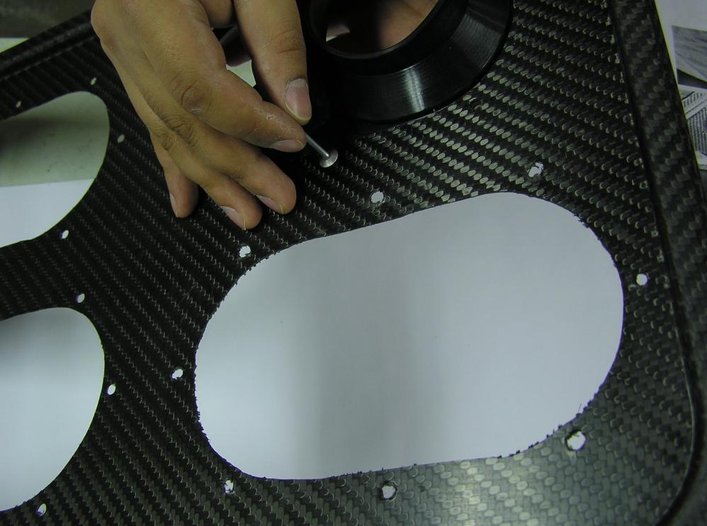
2 Before you begin, make sure that you have the stacks installed on the intake manifold and that they stay installed during the installation process. Being careful to make sure that all stacks are tightly installed and properly seated. If you have an injector system with 5 angled stacks follow the included modified instructions for steps 1 & 9 listed with an asterix. 1) * (See modified step for angled stacks). Place the large clear plastic sheet on top of the stacks, approximately centered (Photo 1). Standing on the driver s side of the motor, carefully look from the top and place a mark at the center point between each stack pair (Photo 2). You should make 4 marks in total (Photo 3). Label them going clockwise from the top left 1, 2, 3 and 4. The points will be referred to by these numbers from now on. Photo 1 Photo 3 2) Lift the plastic sheet from the stacks and place it on a flat surface. Make sure you don t flip or turn over the plastic template at any time. Use a ruler or straight edge to draw diagonal lines from point 1 to point 3 and from point 2 to point 4. You should be drawing only two lines, which make an X. The center of this X is your center mark that you match up to the mark on your base (Photo 4). Photo 2 Photo 4 2
.")
.")
 Place the plastic template on top of the base (the rough side) and line up the center mark on the base with the center of the X on the plastic template.")
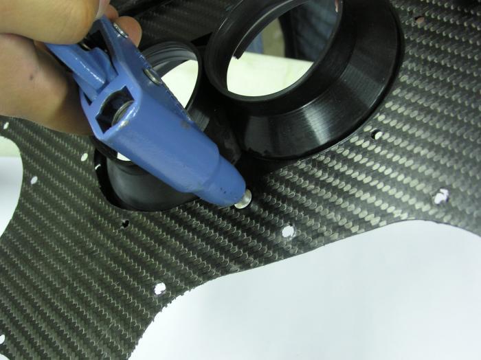
3 3) Draw a horizontal line from point 3 to point 4. This line will be used to square the plastic template to the base (Photo 5). 5) Using a high speed electric drill and a.193 Dia. drill bit, drill through both the plastic and carbon fiber over the points that you marked earlier on the template (Photo 7). As you drill the holes, place a rivet in each hole (without expanding it) to help keep the pieces from shifting as you drill. The holes in the base will be referenced the same way as the points on the plastic template. That is, 1 thru 4 going clockwise starting at the top left (Photo 8). You can now set the square plastic template aside. Photo 5 4) Place the plastic template on top of the base (the rough side) and line up the center mark on the base with the center of the X on the plastic template. Use a ruler to measure the distance between the squaring line and the edge of the base at various points to ensure they are parallel. Double-check your measurements. This properly locates the plastic template over the base. Be careful not to shift the plastic template or base at this point. You can use small clamps to hold the pieces in place if you desire (Photo 6). Photo 7 Photo 8 Photo 6 3
 We recommend the use of a jigsaw with a finetoothed blade for cutting the base.")

 Place the supplied oval template over one of the drilled holes in the base, aligning the hole in the base with the CENTER hole in the template.")
 and draw a line around the oval template.")
4 6) On the base draw a line from hole 1 to hole 2 and from hole 3 to hole 4. These lines will be used to help locate the oval template (Photo 9). 8) We recommend the use of a jigsaw with a finetoothed blade for cutting the base. Start by drilling approximately a 3/8 hole inside the oval markings where you wish to start jigsaw cutting (Photo 11). Then carefully cut out the oval shapes following the INSIDE of the lines that you drew. The cut does not have to be perfect but try and stay inside the line (Photo 12). Do this for all 4 oval holes. Photo 9 7) Place the supplied oval template over one of the drilled holes in the base, aligning the hole in the base with the CENTER hole in the template. Then line up one of the adjacent holes in the template with the line you drew on the base. Hold it in place (you can place a rivet in the center hole to keep it steady) and draw a line around the oval template. Do this for all 4 holes in the base (Photo 10). These ovals will be your cut out lines on the base. Photo 11 Photo 10 Photo 12 9) *(See modified step for angled stacks). Place the included stack seals inside the 4 oval holes that you cut. You will notice that there is some play in the hole/seal interface; this is normal. Take all the components and place them atop your injection 4

. You can now remove the base from the stacks.")

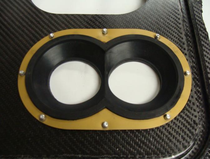
5 stacks (which should still be installed in the intake manifold). Place the base/seals in a manner that allows the bottom of the seals to fall inside the air horns (Photo 13). Once all the seals are located in the air horns, adjust the base as necessary to center everything. Now place a mark on the base through each rivet hole on the seals. As a double check for proper positioning, you can lift out the seals leaving the base atop the stacks. The oval cut outs on the base should be roughly centered over their respective stack pairs (Photo 14). You can now remove the base from the stacks. 10) Place a seal in an oval hole on the base and line it up with the 8 marked rivet hole locations on the base. Using a.193 drill bit and a high-speed drill, drill out 8 holes in the base around each oval cutout using the holes in the stack seals as a guide. As you drill each hole, place a rivet through the hole to keep the stack seal from shifting as you drill the other holes (Photo 15). Do this for all 4 ovals. DO NOT EXPAND THE RIVETS YET. Photo 13 Photo 15 11) All the holes are now cut and you can begin assembly of the base using the provided silicone RTV. Start by cutting the plastic tip so there is approximately a 3/16 hole for the silicone to flow through (Photo 16). Now apply the silicone to the base by laying a continuous bead all the way around an oval cut in the base (Photo 17). Place a seal on top of the silicone you just laid out. Place some silicone on the body of the rivet and insert the rivets from the UNDERSIDE of the base (Photo 18 & 19), then expand them using a pop riveter (Photo 20). It may help to have assistance with this step if using a manual riveter. Do this for all 4 seals. For a cleaner look you may wish to wipe away excess silicone before it cures, however this is not necessary. If done correctly, the installation should look like Photos 21& 22. Photo 14 5


6 Photo 16 Photo 19 Photo 17 Photo 20 Photo 18 Photo 21 6

 A piece of insulating tape has been included to reduce the chance of getting shocked when handling the base and filter on a")
 The supplied silicone gasket can now be installed in the base. Cut the gasket ends at a 30-40 angle.")
. This will ensure that the two mated ends fit perfectly against each other (Photos 26 & 27).")
7 ends. Join the ends and allow the joint to dry for 1 hour before disturbing (Photo 29 & 30). If you wish, immediately after applying silicone to the gasket joint you can apply a piece of scotch tape over the top to hold it together while the silicone dries. Be sure to remove this tape before installing the filter onto the base. Photo 22 12) A piece of insulating tape has been included to reduce the chance of getting shocked when handling the base and filter on a running motor. It should be installed at the closest point between the magneto and filter base (Photo 23). Photo 24 Photo 23 13) The supplied silicone gasket can now be installed in the base. Cut the gasket ends at a angle. This can be done easily by overlapping the gasket ends (side by side) about 1 and cutting down through the material at an angle (Photos 24 & 25). This will ensure that the two mated ends fit perfectly against each other (Photos 26 & 27). Install the gasket by removing the paper backing and installing it into the sealing channel (Photo 28) then apply silicone gasket maker on the cut Photo 25 7


8 Photo 26 Photo 29 Photo 27 Photo 28 Photo 30 14) Now you can install your stacks into the seals. To do this you must remove them from your engine and slide them through the seals. This is a good time to inspect all your stacks and make sure they are not dented or distorted. A damaged stack can cause a poor seal and should be replaced. If you have trouble sliding the stacks through the seals, a tube of P-80 lubricant has been provided for this purpose. Apply liberally to your stacks. Install your stacks through the seals and put on the provided hose clamps loosely around the stacks, so that they do not fall off but still allow adjustment (Photo 31). If you have 3 diameter stacks or larger, you may find you need to turn the base over and spread the stacks apart to get the 8
. Make sure there is sufficient stack length past the seal boot to make this mark on the stack.")

 to be properly seated. Engler and Hilborn systems will vary.")
9 clamps on around the boot (Photo 32). YOU MUST USE THE HOSE CLAMPS TO MAKE A PROPER SEAL! Photo 31 your adapter manufacturer this distance will vary. Take this measurement and place a mark on each of your stacks from the bottom-up (Photo 34). Make sure there is sufficient stack length past the seal boot to make this mark on the stack. Our seals have a longer boot than most other manufacturers seals so it is critical to make sure there is enough stack length below the boot to seat the stack properly into the adapters. If there is not, then push the stack through the seal until there is and make the mark on the stack. Now, install the stacks and filter base onto your engine, making sure to seat the stacks all the way down to the stops in the adapters. THIS IS A KNOWN LEAK PATH FOR DIRT TO GET INTO YOUR ENGINE! For reference, the stacks must slide into Kinsler Injector Bodies about (Photos 33 & 34) to be properly seated. Engler and Hilborn systems will vary. When the stack is correctly seated, the mark you made on the stack should line up with the top of the stack adapter (Photo 35). Photo 36 shows an incorrectly seated stack. Once all the stacks are seated correctly (which can take some effort), you can tighten all the pinch bolts to hold them in place. Photo 32 15) If you have an O-ring type setup (such as the Kinsler stack adapters), which seals the stack against the adapter, this is a good time to check the condition of the o-rings and replace them as necessary. It is essential that you apply a film of heavy grease to the inside of the stack adapters to minimize dirt leakage in this area, even if you have o-rings installed. Using a ruler, measure the distance from the top of one of your stack adapters to the stop inside the adapter where the stack should sit (Photo 33). Depending on Photo 33 9


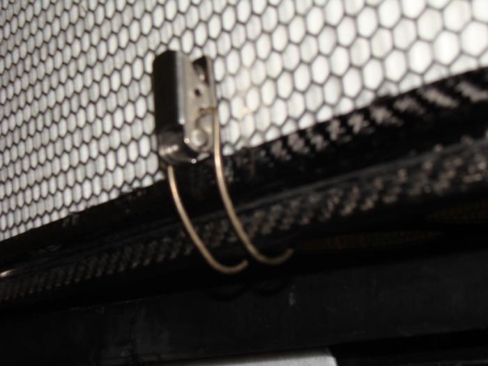
10 Photo 34 Photo 36 Stack Not Fully Seated 16) Once the stacks are attached to the engine, you can adjust the base to the height that you want it. You may need to loosen the hose clamps if you tightened them earlier. If you still have difficulty, use the supplied P-80 lubricant on all the stacks/seals to ease the movement of the base. Once you are happy with the location of the base, tighten all the hose clamps and wipe away any excess P-80 lubricant. Don t worry if you miss some, it will dry up quickly and won t attract dirt. Re-check all the pinch bolts and hose clamps to ensure they are all tight. Photo 35 17) To install the filter to the base, place the wire bale on each filter latch around the sealing channel on the base and pull the latch tight (Photos 37 & 38). Reverse these directions for removal. 10

11 Photo 37 Photo 38 11
12 Use these supplemental instructions for steps 1 & 9 (in lieu of the standard instructions) if you have a fuel injection system with 5 angled stacks. All other steps should be taken directly from the standard instructions. 1) Mark the center point of each stack pair with a marker (Photo 39) then place the large clear plastic sheet on top of the stacks, approximately centered. Standing on the left side of the motor (closest to cylinders 1,3,5,and 7), carefully look from the top and place a mark at the center point between each stack pair (Photo 40). Place these marks directly above the center marks you placed on the stack pairs. You should make 4 marks in total (Photo 41). Once these marks are made DO NOT flip or turn over the plastic template. Now, depending on what height you wish to place the base on the stacks, you must move the marks you just made outward (that is, increase the bank to bank spacing of the 4 marks). This must be done to properly locate the holes in the base due to the angled stacks. Using the table provided mark new points on the template based on your decided base height (i.e. If you wish to mount the base 2 below the top of the stacks, you would move your original marked points outward by approximately.174 or just under 3/16 ) (Photo 42 & 43). If you wish, you may erase your original marks to avoid any confusion later. Label the new marks going clockwise from the top left 1, 2, 3 and 4. The marks will be referred to by these numbers from now on. Distance Below Top of Stack Distance Marked points need to be Moved


13 Photo 39 Photo 42 Photo 40 Photo 41 Photo 43 9) Place the included stack seals inside the 4 oval holes that you cut. You will notice that there is some play in the hole/seal interface; this is normal. Do your best to center each seal within the oval holes. You can use the horizontal lines you drew on the base as a guide to assist you (Photo 44). Once a seal is centered, place a mark on the base through all of the rivet holes as reference marks (Photo 45). Do this for all 4 oval cut outs. 13

14 Photo 44 Photo 45 14
START HERE BEFORE YOU BEGIN FIG 1 STEP 2
 PROFESSIONAL INSTALL RECOMMENDED REAR MODULAR / MULTI LED ROOF MOUNTS PART#: Z350040 / Z350050 REAR ROOF LED LIGHT MOUNTS Parts included (1) - Driver Side Roof Mount Upright (1) - Passenger Side Roof Mount
Frameless Inline Door With Return QCI5263
 INSTALLATION INSTRUCTIONS Frameless Inline Door With Return QCI5263 WALL MOUNT HINGES FRAMELESS DOOR / PANEL / RETURN PANEL QCI5263 REV. 0 Page 1 Certified 06/17/2016 Parts List with wall mount hinges
INSTALLATION INSTRUCTIONS. Deluxe Continuous Hinge Inline Door & Panel Shower Enclosure QCI5230
 INSTALLATION INSTRUCTIONS Deluxe Continuous Hinge Inline Door & Panel Shower Enclosure QCI5230 QCI5230 Rev 0 6 shower new QCI5230 Rev 0 Page 2 Certified 06/20/2016 Parts List A. Curb (w/ weep holes) (1)
Radon 07 Installation Instructions & Parts List
 Radon 07 Installation Instructions & Parts List Illustration Radon 07, H1 Handle Right Hand: Open Out 14/06/2016 Revision 1.1 Page 1 of 21 IMPORTANT This shower screen / enclosure must be installed by
Dubnium 11 Installation Instructions & Parts List
 Dubnium 11 Installation Instructions & Parts List Illustration Dubnium, H1 Handle Right Hand: Open Out Page 1 of 25 IMPORTANT This shower screen / enclosure must be installed by suitably qualified individuals.
Frameless Fixed Panel Slider QCI5279
 Frameless Fixed Panel Slider QCI5279 F AB GLASS AND MIRROR www.fabglassandmirror.com Call: +1 888-474-2221 Fax: (614)-334-4919 Office Timing: 8:30-18:00 EST info@fabglassandmirror.com Frameless Fixed Panel
1/4 FRAMELESS DOOR WITH INLINE PANEL 1413A-1713A-1813A
 1/4 FRAMELESS DOOR WITH INLINE PANEL 1413A-1713A-1813A F AB GLASS AND MIRROR www.fabglassandmirror.com Call: +1 888-474-2221 Fax: (614)-334-4919 Office Timing: 8:30-18:00 EST info@fabglassandmirror.com
B A T H R O O M G L A S S
 mistley B A T H R O O M G L A S S vaug16 Page 2 Thank you for purchasing this Trinity shower screen. Please study these instructions carefully before assembly and installation and check all supplied parts
Frameless Inline Door QCI5254
 INSTALLATION INSTRUCTIONS Frameless Inline Door QCI5254 FRAMELESS DOOR / PANEL QCI5254 REV. 0 Page 1 Cer fied 06/16/2016 Parts List with wall mount hinges *Quanes may vary QCI5254 REV. 0 Page 2 Cer fied
QCI0029 REV. 1 Page 1 of 11 Certified 07/06/05
 QCI0029 REV. 1 Page 1 of 11 Certified 07/06/05 MAINTENANCE: Two primary materials are used to manufacture your new Basco enclosure: tempered glass and anodized aluminum. To assure a long lasting finish
INSTALLATION INSTRUCTIONS FRAMELESS CONTINUOUS HINGE SHOWER ENCLOSURE QCI5232
 INSTALLATION INSTRUCTIONS FRAMELESS CONTINUOUS HINGE SHOWER ENCLOSURE QCI5232 QCI5232 Rev 0 Page 1 Certified 06/20/2016 INSTALLATION NOTES: Unpack your unit carefully and inspect for freight damage. Lay
Frameless Inline Door QCI5248
 INSTALLATION INSTRUCTIONS Frameless Inline Door QCI5248 FRAMELESS PANEL / DOOR / PANEL QCI5248 REV. 0 Page 1 Certified 06/16/2016 Parts List with glass to glass hinges *Quantities may vary. **Support Bar
SIDE SLIDING/ FIXED WINDOWS
 SIDE SLIDING/ FIXED WINDOWS ILLUSTRATED FITTING MANUAL You will need: General workshop tools Cloths and a mild cleaning agent Latex gloves, eye and ear protection An electric drill with an appropriate
Gallium 03 Installation Instructions & Parts List
 Gallium 03 Installation Instructions & Parts List Illustration Gallium 03, H1 Handle Left Hand: Open Out 04/05/2016 Revision 1.1 Page 1 of 19 IMPORTANT This shower screen / enclosure must be installed
INSTALLATION AND CARE INSTRUCTIONS
 INSTALLATION AND CARE INSTRUCTIONS Skylight Manually Operated Honeycomb Shades 20 C8-10-1806 2/15 1 INTRODUCTION Thank you for purchasing our product. Your new shade has been custom built for you from
675 Quick N Stall Neo Angle Framed Hinge Shower Enclosure
 INSTALLATION INSTRUCTIONS 675 Quick N Stall Neo Angle Framed Hinge Shower Enclosure Call Technical Dept @ 1-800-452-2726 QCI1003 Page 1 of 9 Certified 10/01/09 INSTALLATION NOTES: Unpack your unit carefully
INSTALLATION INSTRUCTIONS FRAMELESS CONTINUOUS HINGE SHOWER ENCLOSURE QCI5233
 INSTALLATION INSTRUCTIONS FRAMELESS CONTINUOUS HINGE SHOWER ENCLOSURE QCI5233 QCI5233 Rev 0 Page 1 Certified 06/20/2016 INSTALLATION NOTES: Unpack your unit carefully and inspect for freight damage. Lay
Curium 19H Installation Instructions & Parts List
 Curium 19H Installation Instructions & Parts List Illustration Curium 19H Right Hand Page 1 of 15 01/07/2016 Revision 2.1 IMPORTANT This shower screen / enclosure must be installed by suitably qualified
Curium 19.4H Installation Instructions & Parts List
 Curium 19.4H Installation Instructions & Parts List Illustration Curium 19.4H Right Hand Page 1 of 21 30/06/2016 Revision 1.0 IMPORTANT This shower screen / enclosure must be installed by suitably qualified
PAGE 1 OF 6 FITTING INSTRUCTIONS FOR CAMEC 4 RADIUS CORNER SLIMLINE WIND OUT WINDOW. Rev 3 change all cutout radiuses from 55mm to 68mm.
 PAGE 1 OF 6 FITTING INSTRUCTIONS FOR CAMEC 4 RADIUS CORNER SLIMLINE WIND OUT WINDOW Rev 3 change all cutout radiuses from 55mm to 68mm. PAGE 2 OF 6 1. To install Camec 4RC window correctly please follow
Frameless Inline Door QCI5250
 INSTALLATION INSTRUCTIONS Frameless Inline Door QCI5250 FRAMELESS PANEL / DOOR / PANEL QCI0249 REV. 3 Page 1 Certified 10/12/12 Parts List with pivot hinges *Quantities may vary. QCI0249 REV. 3 Page 2
FIXED SHOWER SCREEN For Wall Mount Hinges QCI5283
 FIXED SHOWER SCREEN For Wall Mount Hinges QCI5283 QCI5283 Page 1 Date Certified: 06/16/2016 Parts List with wall mount clamp ITEM NO. DESCRIPTION QTY. 1 FIXED GLASS PANEL 1 2 WALL MOUNT CLAMP 1 3 U-CHANNEL
FRAMELESS DOOR / PANEL WITH WALL MOUNT HINGES QCI5274
 FRAMELESS DOOR / PANEL WITH WALL MOUNT HINGES QCI5274 QCI0274 QCI5274 REV. Rev. 1 0 Page Page 1 1 Date Certified: Certified 06/16/2016 10/01/10 Parts List with wall mount hinges ITEM NO. Part # DESCRIPTION
INSTALLATION INSTRUCTIONS 960 RODA GLASS TO GLASS HINGES ANGLED FRAMELESS PANEL / DOOR / PANEL CELESTA DRESDEN TRESOR
 INSTALLATION INSTRUCTIONS 960 RODA GLASS TO GLASS HINGES NEED INSTALLATION HELP? Call 1-800-45-BASCO (452-2726) Monday - Friday 8:00 A.M. - 4:30 P.M. Eastern Time ANGLED FRAMELESS PANEL / DOOR / PANEL
TOYOTA MOTOR EUROPE CA Products Division Tel : Fax :
 TOYOTA MOTOR EUROPE CA Products Division Tel : + 32 2 745 26 77 Fax : + 33 2 745 26 99 Ordering part numbers Comments Part Numbers Wooden floor one hatch PZ449-D3C42-11 one hatch with carpet PZ449-D3C42-01
Frameless Fixed Panel Slider
 INSTALLATION INSTRUCTIONS Frameless Fixed Panel Slider QCI-5279 SINGLE ROLLER WITH ANTI-JUMP DOUBLE ROLLERS QCI5279 Rev Page Certified 08/09/6 Tools: To install your New Shower Enclosure, you may need
Hardware and Components:
 Hardware and Components: (A) 5/16 x 2 Hex Bolt (B) 5/16 x 2-1/4 Hex Bolt (C) 5/16 x 2-1/2 Hex Bolt (D) 4X 5/16 x 3/4 Hex Bolt (E) 4X 5/16 x 1-1/4 Hex Bolt (F) 11X 5/16 Flat Washer (G) 12X 5/16 Nylock Nut
Hardware and Components:
 Hardware and Components: (A) 4X 5/16 x 1 Carriage Bolt (B) 2X 5/16 x 2-1/4 Carriage Bolt (C) 2X 5/16 x 3-1/4 Hex Bolt (D) 2X 5/16 x 3/4 Hex Bolt (E) 2X 5/16 x 1-1/4 Hex Bolt (F) 5/16 x 2-1/4 Hex Bolt (G)
392CV SERIES Stickstall
 202 Anderson Ave., Belvue, KS 66407 Phone: 800-669-9867 Fax: 800-393-6699 www.onyxcollection.com 800-643-1514 www.alumaxshowerdoor.com 392CV SERIES Stickstall TM Corner Shower Enclosure 392CV-1117 Yes!
Deauville Installation Guide
 vjul16 (for 17 or 24 mm Surface Wall Profiles) DO NOT ASSEMBLE WITHOUT FULLY READING THESE INSTRUCTIONS Page 2 Thank you for purchasing this Deauville shower enclosure. Please study these instructions
2012+ F30 320i, 328i F22 228i Carbon Fiber S-FLO Intake INSTALLATION GUIDE FOR RACING USE ONLY
 PERFORMNCE ENGINEERING FOR EUROPEN UTOS INSTLLTION GUIDE 2012+ F30 320i, 328i 2014+ F22 228i Carbon Fiber S-FLO Intake FOR RCING USE ONLY Congratulations on your purchase of the WE Tuning Carbon Fiber
A-935 RODA WALL MOUNT HINGES
 INSTALLATION INSTRUCTIONS A-935 RODA WALL MOUNT HINGES NEED INSTALLATION HELP? Call 1-800-45-BASCO (452-2726) Monday - Friday 8:00 A.M. - 4:30 P.M. Eastern Time FRAMELESS DOOR / PANEL CELESTA QCI0274 REV.
EMO. Service Instruction. created by Frank Weithöner. Table of contents: Special Tools Assembling Mixing Chamber
 EMO Service Instruction created by Frank Weithöner Table of contents: - Special Tools Disassembling Mixing Chamber Assembling Mixing Chamber Adjustment Rotor / Level Indicator Unit Temperature Compensating
How to Build an Advanced Composite Clipboard
 How to Build an Advanced Composite Clipboard Tools and Equipment Measuring Tape Black Sharpie Silver Sharpie Rivet Puller Tile Saw or Hacksaw Drill and Drill Bits (5/32) Scissors Utility Knife Straight
Slide the stock rubber tank mount caps onto the ends of the CS-1 tank mount:
 RYCA CS-1 BODY PARTS INSTALLATION GUIDE [The CS-1 installation guides should be used as supplements to the videos found on our Youtube Channel. There is no strict order to the build process, but it is
MACHINE QUILTING FRAME
 MACHINE QUILTING FRAME YOU WILL NEED TO PURCHASE: 5 pieces of 1-1/4 thin wall metal conduit (EMT) cut to your preferred length for the rollers. (Maximum 120 ) DETERMINING YOUR ROLLER LENGTH: Determine
INSTALLATION INSTRUCTIONS 935 RODA GLASS TO GLASS HINGES FRAMELESS DOOR / PANEL CELESTA DRESDEN GEOLUX TRESOR VONSE
 INSTALLATION INSTRUCTIONS 935 RODA GLASS TO GLASS HINGES NEED INSTALLATION HELP? Call 1-800-45-BASCO (452-2726) Monday - Friday 8:00 A.M. - 4:30 P.M. Eastern Time FRAMELESS DOOR / PANEL CELESTA DRESDEN
EXPRESS ASSEMBLY MANUAL SECTION 3 F5-RG/FT WING ASSEMBLY. Procedure 3.155A WING CLOSE-OUT PROCEDURES
 Procedure 3.155A WING CLOSE-OUT PROCEDURES In this procedure The lower wing skin will be bonded to the upper wing For this procedure, the following parts will be required: Part Number Description Qty 111-11-060-01
Elara NanoEdge Fixed Frame Screen User Guide
 Elara NanoEdge Fixed Frame Screen User Guide INTRODUCTION INTRODUCTION WARNING This product may contain sharp edges, please handle with care. Protective gloves are recommended. A minimum of two people
INSTALL/REMOVAL INSTRUCTIONS: WINDOW REGULATOR
 REMOVAL/INSTALL OF WINDOW REGULATOR (741-584) Ford Focus 2000-2007 General Tech Tips: Use painter s tape rather than duct tape to secure window. It will not damage paint or leave sticky residue. A plastic
Xenon 05 Installation Instructions & Parts List
 Xenon 05 Installation Instructions & Parts List Illustration Xenon 05, H1 Handle Left Hand: Open Out 26/05/2016 Revision 2.1 Page 1 of 19 IMPORTANT This shower screen / enclosure must be installed by suitably
Unit No. 1413NP, 1713NP, 1813NP Infinity Continuous Hinge Frameless Door & Inline Panel with No Post Shower Enclosure
 INSTALLATION INSTRUCTIONS Unit No. 1413NP, 1713NP, 1813NP Infinity Continuous Hinge Frameless Door & Inline Panel with No Post Shower Enclosure QCI0239 Page 1 of 12 Certified 8/2/10 MAINTENANCE: Two primary
Heavy Wall Applied Stop Tube Frame and Door Installation
 INSTALLATION INSTRUCTIONS Heavy Wall Applied Stop Tube Frame and Door Installation Read all instructions before beginning installation. These instructions are provided to help prevent installation problems
SGTalon s Enterprise-A Foamie Build Guide. SGTalon s. Enterprise. Enterprise--A. Assembly Instructions
 SGTalon s Enterprise SGTalon s Enterprise--A Enterprise Assembly Instructions Page 1 4-13-2013 SGTalon s Enterprise *******Recommended Hardware******** 2.6oz 250w Motor and Speed Control with 8x6 prop
Hatchback Wing Riser Kit
 Hatchback Wing Riser Kit 2015-06-11 Thank you for purchasing this PERRIN product for your car! Installation of this product should only be performed by persons experienced with installation of aftermarket
Fortress Fe Posts must always be secured to the deck framing. Fortress Fe Posts should never be attached to only the deck boards.
 Installation Instructions for Fortress Horizontal Cable Panel System with UB-05 Brackets and Fe Posts It is the responsibility of the installer to meet all code and safety requirements, and to obtain all
Maintenance Information
 16601023 Edition 2 January 2014 Air Impact Wrench 2705P1 Maintenance Information Save These Instructions Product Safety Information WARNING Failure to observe the following warnings, and to avoid these
Inventory (Figure 2)
") MODEL T10127 12" SPIRAL CUTTERHEAD INSTRUCTIONS The Model T10127 indexable insert spiral cutterhead is designed to replace the straightknife cutterhead from the Grizzly jointer Model G0609. The total procedure
MODEL T10127 12" SPIRAL CUTTERHEAD INSTRUCTIONS The Model T10127 indexable insert spiral cutterhead is designed to replace the straightknife cutterhead from the Grizzly jointer Model G0609. The total procedure
Complete Dovetail Jig Instructions
 Complete Dovetail Jig Instructions 15 18 4 3 1 12 13 8 19 17 16 6 14 5 9 11 10 2 9 PARTS LIST - Complete Dovetail Jig Introduction Your new dovetail jig will cut Full Through Dovetails and three varieties
Constable Oak Extension Dining Table
 Constable Oak Extension Dining Table Assembly Instructions - Please keep for future reference 176/0325 Dimensions Width - 160/ 200cm Depth - 90cm Height - 75cm Important - Please read these instructions
for Rigid Sun Lite Planning the layout
 for Rigid Sun Lite These instructions refer to installations on a flat and pitched roof. Various roof flashing units are available according to the particular roof covering. The roof flashing will be boxed
INSPECTION AND CORRECTION OF BELLHOUSING TO CRANKSHAFT ALIGNMENT
 INSPECTION AND CORRECTION OF BELLHOUSING TO CRANKSHAFT ALIGNMENT BACKGROUND Proper alignment of the transmission input shaft to the crankshaft centerline is required in order to achieve the best results
Installing your new Bevella Top. L Shaped Countertop with Joints No Finished Ends (Fits Between Four Walls)
") Installing your new Bevella Top L Shaped Countertop with Joints No Finished Ends (Fits Between Four Walls) Bevella RTI Countertops are engineered and manufactured to the highest quality standards, built
Installing your new Bevella Top L Shaped Countertop with Joints No Finished Ends (Fits Between Four Walls) Bevella RTI Countertops are engineered and manufactured to the highest quality standards, built
Corvus Racer CC
 Corvus Racer 540 35CC Item No:L-G035008 Specifications Wing Span Length Wing Area Flying Weight Glow Gasoline Electric Radio mm mm 1200sq in (77.4sqdm) 9.9-12lbs(4.5-5.5kg) 91-1.20(2C) 1.10-1.40(4C) 20-40cc
Installation for Full Size Polaris Ranger Crew Doors
 Installation for Full Size Polaris Ranger Crew Doors Order of Installation: Heater Doors Wiper on to Windshield Windshield Top & Back Panel Note: Most of the steps in these instructions need to be repeated
Pump Replacement Manual. Bill Wallace by Wallace Marine Services, Inc.
 by Wallace Marine Services, Inc. Maintain Your Equipment The Easy Way Bill Wallace 843-693-4336 info@willyvac.com www.willyvac.com Pump Replacement Manual 1 How to change the water pump on the Willy Vac
Grade 11 Woods Lift Lid Coffee Table. Based on Under the big Top from Popular Mechanics Website
 Grade 11 Woods Lift Lid Coffee Table Based on Under the big Top from Popular Mechanics Website TABLE TOP 1. Select enough lumber to construct a top that is between 22 ½ and 24 wide after jointing. Ensure
11) Chromate the mating surfaces of the Leading edge Root Rib, Doubler and Root Rib Stiffeners. Rivet together with 1/8 rivets (RV-1410).
 Chromate the mating surfaces of the Leading edge Root Rib, Doubler and Root Rib Stiffeners. Rivet together with 1/8 rivets (RV-1410).") 11) Chromate the mating surfaces of the Leading edge Root Rib, Doubler and Root Rib Stiffeners. Rivet together with 1/8 rivets (RV-1410). 12) Chromate the Root Rib Attach Bracket and rivet to the Root
11) Chromate the mating surfaces of the Leading edge Root Rib, Doubler and Root Rib Stiffeners. Rivet together with 1/8 rivets (RV-1410). 12) Chromate the Root Rib Attach Bracket and rivet to the Root
Aluminum Clad Wood Window 1/2 Reinforced Field Mulling and Stacking Supplement
 Aluminum Clad Wood Window 1/2 Reinforced Field Mulling and Stacking Supplement 1 Aluminum Clad Wood Window 1/2 Reinforced Field Mulling and Stacking Supplement The following instructions are a supplement
MMD Convertible Styling Bar Customer Installation Guide
 MMD Convertible Styling Bar Customer Installation Guide TOOLS REQUIRED/RECOMMENDED: Electric Drill 1 Forstner Bit (Hole Saw) 1 3/8 Hole Saw (manual calls for 1 ¾ ) 1/8, 3/8 & ¾ Drill Bits Rivet Gun Trim
Monaco Installation Guide - Surface Profiles
 v1 Page 1 Thank you for purchasing this Monaco shower screen. Please study these instructions carefully before assembly and installation and check all supplied parts immediately upon receipt. These instructions
 www.wildmanconstruction.com Changing your toilet is an easy project that should take half a day or less. The most common toilet has a separate tank that mounts on top of the bowl. These instructions apply
A SRF/SERF A SRF/SERF
 A1100-055SRF/SERF A1100-056SRF/SERF Remote Fill Assembly INSTALLATION INSTRUCTIONS **CRITICAL - MUST READ** This unit can only be used for new installations or tank level retrofits that allow access to
FRAMED PANEL / DOOR / PANEL CONTINUOUS HINGE SHOWER ENCLOSURE INSTALLATION INSTRUCTIONS
 FRAMED / DOOR / CONTINUOUS HINGE SHOWER ENCLOSURE INSTALLATION INSTRUCTIONS QCI5229 Rev 0 6 INSTALLATION NOTES: Unpack your unit carefully and inspect for freight damage. Lay out and identify all parts
Bath Accessory Installation
 Bath Accessory Installation Step 1 - Clean surface using a clean dry cloth or use rubbing alcohol to remove any residue (wax, grease, solvents). Allow to dry one hour. Caution! DO NOT use any household
Bushwacker Jeep Flat Style Fender Flares Rear Pair (JK Wrangler 2dr)
") Bushwacker Jeep Flat Style Fender Flares Rear Pair (JK Wrangler 2dr) Note: These instructions involve cutting parts of your vehicle. Please read all instructions prior to starting. Installation Time: 3-4
Bushwacker Jeep Flat Style Fender Flares Rear Pair (JK Wrangler 2dr) Note: These instructions involve cutting parts of your vehicle. Please read all instructions prior to starting. Installation Time: 3-4
Extendable Large Dovetail Jig
 Extendable Large Dovetail Jig Instruction Manual Part # 3458 CAUTION: Please read, understand, and follow all manufacturers instructions, guidelines and owners manuals that come with your power tools.
Tech Sheet. T4 Interior conversion kit how to - fitting instructions. 1. Rear seat belts. 2.
 Page 1 of 8 T4 Interior conversion kit how to - fitting instructions Thank you for purchasing our T4 interior conversion kit. This kit will enable you to convert any SWB left hand loading door T4 into
Tapping Screw (W/Flange) 46 Cord Armor 47 Tube (D) 48 Cord. 45 Cord Clip. Tapping Screw (W/Flange) 10 Gear Cover Ass'y. 12 Socket (B) Ass'y
 46 Cord Armor 47 Tube (D) 48 Cord. 45 Cord Clip. Tapping Screw (W/Flange) 10 Gear Cover Ass'y. 12 Socket (B) Ass'y") W8VB The exploded assembly drawing should be used only for authoized service center. W8VB Item No. Part time 1 Magnetic Hex. Socket 2 Sub Stopper 3 O-Ring (S-16) 4 Locator (A) 5 Lock Sleeve (A) 6 O-Ring
W8VB The exploded assembly drawing should be used only for authoized service center. W8VB Item No. Part time 1 Magnetic Hex. Socket 2 Sub Stopper 3 O-Ring (S-16) 4 Locator (A) 5 Lock Sleeve (A) 6 O-Ring
1/4 FRAMELESS CONTINUOUS HINGE SHOWER ENCLOSURE 1400A-1700A-1800A
 1/4 FRAMELESS CONTINUOUS HINGE SHOWER ENCLOSURE 1400A-1700A-1800A F AB GLASS AND MIRROR www.fabglassandmirror.com Call: +1 888-474-2221 Fax: (614)-334-4919 Office Timing: 8:30-18:00 EST info@fabglassandmirror.com
400A 40113V, 401A 40120V, & 401AL 40120VL ALUMINUM VERTICAL 4000 LB LIFT INCLUDES SCREW LEG ASSEMBLY INSTRUCTIONS
 12/11/07 PAGE 1 OF 12 400A 40113V, 401A 40120V, & 401AL 40120VL ALUMINUM VERTICAL 4000 LB LIFT INCLUDES SCREW LEG ASSEMBLY INSTRUCTIONS Thank you for purchasing our product! *Please read these instructions
SECTION side windows round corners
 03-701.00/ 1 SECTION 03-701.00 2011SE08 GENERAL DESCRIPTION The windows installed on Nova vehicles may be a onepiece fixed type, or may consist of an upper and lower section, separated by a transom. The
Step-by-Step Installation Instructions for
 Step-by-Step Installation Instructions for Customer helpline number: 01604 633607 8892_Step_By_Step_900_Quad_V5.indd 1 1/9/10 18:01:22 Before Starting: Please read and understand these instructions. Not
Installation Guide 1
 1 2 Contents Before you begin Storage & preparation Tools & materials you may need Getting started Sink & cooktop cut-outs Cabinet Joins for 20mm benchtops Joining & installation of 20mm benchtops Joining
INSTALLATION INSTRUCTIONS
 INSTALLATION INSTRUCTIONS BUILDERS CHOICE FRAMED Bypass Door Model: L0516 (Tub Height), L0517 (Shower Height) Rev. 09.20.13 INSTALLATION NOTES: Unpack your unit carefully and inspect for freight damage.
C70 Window Roller Repair Taken from: Heres the problem:
 C70 Window Roller Repair Taken from: http://www.volvospeed.com/vs_forum/topic/115086-how-to-c70-window-rollers-permanent-fix/ Heres the problem: This happened to two separate window assemblys on my c70
tile redi redi DOOR Redi Redi Swing Slide g TM TM...Opening Doors to Stunning Showers! TM TM SERIES: CONFIGURATION: MOUNTING PACKAGE:
 redi DOOR INSTALLATION INSTRUCTIONS tile redi Redi Redi Swing Slide g TM TM...Opening Doors to Stunning Showers! TM TM SERIES: CONFIGURATION: MOUNTING PACKAGE: 1100 Door-Door Framed sliding doors RDQCI5023
Braille Repair 101 PRESENTED BY: THE GEORGIA BRAILLE TRANSCRIBERS. The problem with 90% of inoperable braillers is that they need to be cleaned!
 Braille Repair 101 PRESENTED BY: THE GEORGIA BRAILLE TRANSCRIBERS The problem with 90% of inoperable braillers is that they need to be cleaned! Supplies needed: PERKINS BRAILLER STEP BY STEP CLEANING
LED Thin Frame Fixed Frame Screen User Guide
 LED Thin Frame Fixed Frame Screen User Guide INTRODUCTION INTRODUCTION WARNING - Sharp Edges This product may contain sharp edges, please handle with care. Protective gloves are recommended. WARNING -
PLEASE SPEND 5 MINUTES READING THESE INSTRUCTIONS BEFORE USING YOUR NEW RIVET TOOL. TRUST US, IT WILL SAVE YOU TIME AND INCONVENIENCE IN THE LONG RUN.
 PLEASE SPEND 5 MINUTES READING THESE INSTRUCTIONS BEFORE USING YOUR NEW RIVET TOOL. TRUST US, IT WILL SAVE YOU TIME AND INCONVENIENCE IN THE LONG RUN. READ THIS MANUAL CAREFULLY BEFORE USING THE TOOL!
UNIT No. 1415NP / 1715NP / 1815NP INFINITY FRAMELESS CONTINUOUS HINGE SHOWER ENCLOSURE WITH NO INLINE POST
 INSTALLATION INSTRUCTIONS UNIT No. 1415NP / 1715NP / 1815NP INFINITY FRAMELESS CONTINUOUS HINGE SHOWER ENCLOSURE WITH NO INLINE POST QCI0240 Page 1 of 13 Certified 8/2/10 INSTALLATION NOTES: Unpack your
MODEL H " BYRD SHELIX CUTTERHEAD INSTRUCTIONS
 MODEL H9291 12" BYRD SHELIX CUTTERHEAD INSTRUCTIONS The Model H9291 12" Byrd Shelix cutterhead is designed to replace the straight-knife cutterhead on the Grizzly jointer Model G0609. The total procedure
Installation Instructions Palladium Wall Panels - Demountable Factory Finished Edges and Field Cut Edges
 Please read all instructions before installing Palladium Wall Panel System. 1. Before installation: a. Acclimate Palladium Panels, reveals, adhesives and wall substrates to room temperature 24 hours before
Deauville Installation Guide
 vjul16 (for Recessed Wall Profiles) DO NOT ASSEMBLE WITHOUT FULLY READING THESE INSTRUCTIONS Page 2 Thank you for purchasing this Deauville shower enclosure. Please study these instructions carefully before
SETTING UP THE MODEL 210B-2 SRA
 SETTING UP THE MODEL 210B-2 SRA SAFETY PRECAUTIONS FOR THE MODEL 210B-2 SRA System Under Pressure: Shut off air supply and disconnect air hose before disassembling or disconnecting parts. Flying Debris:
Work Space Set-up. Slats will level the pipe during bending and help minimize twisting of the bow.
 Work Space Set-up Affix pipe bender to end of working surface Slats will level the pipe during bending and help minimize twisting of the bow. Make the slat height equal the distance from your work surface
ARTS AND CRAFTS CHAIR
 ARTS AND CRAFTS CHAIR 491 MATERIALS LIST--DINING CHAIR Key No. Size and description (use) A 2 1-3/4 x 1-3/4 x 16-1/4'' oak (front leg) B 2 1-3/4 x 3-3/4 x 40-1/2'' oak (rear leg) C 1 1-3/4 x 3-3/16 x 15''
Traditional Wall Mounted Potfiller
 TOOLS NEEDED FOR INSTALLATION 1/4 hex wrench (provided in installation kit) 3/32 hex wrench (provided in installation kit) Pencil or marker PTFE tape Small level, or carpenters square Power Drill with
ProLine PL60 HEAVY FRAMELESS BYPASS BATH ENCLOSURE
 INSTALLATION INSTRUCTIONS ProLine PL60 HEAVY FRAMELESS BYPASS BATH ENCLOSURE Copyright Alumax Bath Enclosures 2013. All rights reserved. G03980847 5-1-13 !WARNINGS! INSTALLATION WARNINGS a) Alumax Bath
STYLE BAR & TONNEAU COVER INSTALLATION
 STYLE BAR & TONNEAU COVER INSTALLATION INSTALLATION MANUAL: 2005 to '09 Mustang P/N: 10-8002-C12071B Saleen Performance, Inc. 1225 East Maple Rd., MI 48083 800-888-8945 www.saleen.com 1 IF YOU ARE NOT
TREX TRANSCEND RAILING
 RAILING NOTES:» RAILINGS ARE DESIGNED TO BE INSTALLED OVER THE DECKING FRAME OR ON INSIDE OF RIM JOIST. NOTCHING OF PRESSURE-TREATED POSTS OR POSTS INSTALLED ON OUTSIDE OF RIM JOIST IS NOT ALLOWED.» All
FIXED PANEL SLIDER QCI5241
 INSTALLATION INSTRUCTIONS FIXED PANEL SLIDER QCI5241 FRAMELESS PANEL / DOOR / PANEL FRAMELESS DOOR / PANEL QCI5241 REV. 0 Page 1 Certified 06/16/2016 Parts List *Quantities may vary QCI5241 REV. 0 Page
SAFETY AND OPERATING MANUAL. Portable versatile workstation
 SAFETY AND OPERATING MANUAL Original instructions Portable versatile workstation wu063 1 2 3 4 5 6 7 8 9 Safety instructions Warning! When using this product basic safety precautions should always be followed.
 GENERAL OPERATIONAL PRECAUTIONS WARNING! When using electric tools, basic safety precautions should always be followed to reduce the risk of fire, electric shock and personal injury, including the following.
Technicians of Terror. This is the air valve we make to use with our air
 These are pictures of our scissor prop. Technicians of Terror http://www.halloweenfear.com/scissorprop.html props. This is the air valve we make to use with our air This pictures the duel door closer cylinders
Axles Covered in This Bulletin. How to Obtain Additional Maintenance, Service and Product Information. Product Design Variations. How to Obtain Kits
 Technical Bulletin Revised 09-7 Carrier-to-Housing Joint Reseal Procedure Service procedure to be used any time a carrier is removed and reinstalled. Includes tapered dowel installation information. All
Frameless Bypass Slider
 INSTALLATION INSTRUCTIONS Frameless Bypass Slider QCI-5301 Heavy Glass Bypass Slider with Exposed Rollers QCI5301 Rev 0 Page 1 Certified 11/1/2016 Tools: To install your New Shower Enclosure, you may need
Rev B C-RING TOOL VA0375 ½ in. OPERATING MANUAL
 Rev B 4-30-0 C-RING TOOL VA0375 ½ in. OPERATING MANUAL Operational Instructions for Vertex C-Ring Tool VA0375 Vertex Fasteners is committed to providing our customers with world-class customer service
1. Turn off or disconnect power to unit (machine). 2. Push IN the release bar on the quick change base plate. Locking latch will pivot downward.
. 2. Push IN the release bar on the quick change base plate. Locking latch will pivot downward.") Figure 1 Miniature Quick Change Applicators, of the end feed type, are designed to crimp end feed strip terminals to prestripped wires. Each applicator is set up to accept the strip form of certain specific
Figure 1 Miniature Quick Change Applicators, of the end feed type, are designed to crimp end feed strip terminals to prestripped wires. Each applicator is set up to accept the strip form of certain specific
for Flexi Sun Lite Planning the layout
 for Flexi Sun Lite These instructions refer to installations on a flat and pitched roof. Various roof flashing units are available according to the particular roof covering. The roof flashing will be boxed