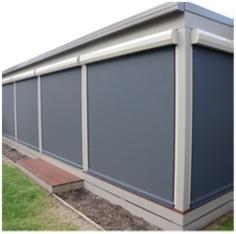
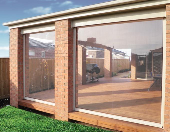
Ziptrak. Overview. Ziptrak system considerations. Ziptrak Vertical screening ideal for outdoor restaurants, patios, verandas, corporate signage.
|
|
|
- Lesley Mills
- 6 years ago
- Views:
Transcription


1

2 Overview Vertical screening ideal for outdoor restaurants, patios, verandas, corporate signage. Operating big window and pergola blinds has been a difficult task for many people. Conventional spring loaded blinds have to be pulled down and held down against the tension of the springs while the operator struggles to do up the buckles or leather straps. This is time consuming, cumbersome and that s why was developed. The guide system has no ropes, no zips, no straps and no buckles. It s unique slotted side tracks, between which the blind glides smoothly and easily up and down and stops where you want it, sets the blind system apart from any other. Featuring a wide choice of fabrics including popular clear and tinted PVC, and various shade mesh solutions, can provide shelter from the elements, provide UV protection and will complement any outdoor entertaining area. system considerations Track Guided Blind System is the ideal solution for all your Vertical Screening needs. Ideal for Home or Business using clear PVC, shade mesh or acrylic shade fabrics. The screening system is easy to install and operate while offering superior performance. Please consider the following when quoting the system. KEY TUBE 63 mm Diameter anodized aluminium top keyway tube is used by all authorised fabricators. MAXIMUM BLIND SIZES (USING 63 MM DIAMETER KEYWAY TUBE) The Helper Spring is to be pre-tensioned anti-clockwise which is opposite to the Standard Spring in the other end. After installing the blind on to the brackets, all final spring tension is then done via the Standard Spring only. Please contact your distributor should you have any queries about oversize blinds. HANDLES (For blinds with enclosed steel base bar only) Use only the recess handle on all blinds as a standard. Use the protruding grab handle only when the blinds are to be accessed from both sides (i.e. 1 recess handle and 1 grab handle back to back). Clear PVC blinds should not exceed 3.5 m wide or 3.0 m height. Mesh fabrics should not exceed 4.0 m wide or 3.0 m height. OVERSIZE BLINDS (USING 78 MM DIAMETER KEYWAY TUBE) PVC blinds over 3.5 m wide and solar shade blinds over 4 m wide can be fabricated using 78 mm anodized aluminum key tube. A 63 mm 1370 Helper Spring and 78 mm adaptors are required with each larger blind. The Helper Spring is fitted to the idler end and must also be pre-tensioned during installation (approximately 10-15x turns).
3 Measuring MEASUREMENTS REQUIRED Overall drop height Top reveal width Overall minimum reveal width (either top, centre or bottom) The structure also needs to be fairly square and straight as the system can only pick up about 20mm of adjustment through the tracks and U channels. Otherwise packers need to be considered to make the structure true. Prepare Blind 1.The spring in the Blind must be pre-tensioned before it is hung on to the brackets. 2.Each blind will vary depending on its size and the fabric weight. As a guide a blind 2.4m high and 3m wide would need around 25 turns for PVC and 20 turns for mesh type fabrics. This may be even more for larger blinds. 3.Wind the spring up using vice grips and using the clip (pawl) on the end of the spring, lock the spring. Installation ZIPTRAK INSTALLATION ON SITE Mounting Brackets or Pelmet 1.It is important to ensure that the Blind is mounted level across the opening whether using pelmets or cast brackets. 2.Be mindful of rafters, gables, down pipes and/or other obstructions that may contact the blind once installed. 3.Generally the Blind should be mounted as high as possible in or over an opening so as to prevent large gaps over the blind when it is in the down position. Prepare Tracks 1.The tracks (top end) must be filed smooth on the inside to allow the Guide Funnel to be installed easily and to remove any burrs in the track opening that may cause unnecessary wear on the spline tape. Using a short length of Cordura Tape i.e. 300 mm, check all tracks for any sharp edged for foreign matter before installation. 2.Once filed the Guide Funnel can be inserted into the Track top end and using a hammer tap the Funnel in until it sits flush against the Track. 3.Remove any excess plastic that may have come off the Guide Funnel. 4.Turn the track over so that you can drill a 4 mm hole into the back of the track and into the Guide Funnel. 5.Drill the hole centred, 10 mm down from the end of the Aluminium Track and using a 4 mm diameter 7 mm long pop rivet fix the Guide Funnel in place. Install Blind 1.Install the Blind, idler end first 2.With the idler end already in, insert the spring end of the blind into the bracket or pelmet end. 3.Ensure that the spring clip (pawl) is positioned at the bottom so that the clip can be accessed from under the blind. This is to enable the spring tension to be adjusted later if necessary. Install Channels and Face Fix Angles 1.The cast brackets are self locating via their leg inserted into the bracket channel. These are installed as a pair (1 left hand side 1 right hand side). 2.When mounting Blinds as a Face fix installation, 20mm x 40mm aluminium angles must be used. 3.The angle if installed with a pelmet should be cut to match the angle of the pelmet end. 4.When used with brackets the angle can be cut at ninety degrees. 5.If face fitting with brackets the 40 x 20 angle needs to be cut to the same length as the track and channel. 6.Fixing of the channel to the angle should be done using 4 mm stainless steel rivets with fixings no more than 600mm apart. The channel to be fixed flush with the outside 40 mm edge. 7.Stainless steel rivets are used as they have far greater shear strength, aluminum rivets will fail. 8.Fixing of the angle or channel to the posts or wall should be done using at least 40mm long screws with spacings of no more than 600mm. 9.The U channel has provision to accept even tech screw heads without affecting the adjustment scope of the track. 10.When cutting the channel it is easy enough to insert the track with the Guide Funnel already in place to enable cutting of both at the same time.
4 Installation - continued 11.Setting the Guide Funnel end of the track flush with the end of the channel, you can measure once and cut both components together, saving measuring and cutting time. Fitting of Bottom Bar Track Guides Aluminium Bottom Bar 1. Make sure that the bottom bar is sitting in form each end of the PVC spline by an equal distance, usually between 4 and 4mm. 2. Insert the bottom bar guide into the bottom bar and fasten it with the supplied screw and repeat on the other side. Steel Bottom Bar 1.Make sure that the bottom bar is sitting in from each end of the Pocket by an equal distance, usually between 3 and 4mm (Cordura spline). 2.Insert the spline tape into the bottom bar ensuring that the bottom bar is sitting squarely inside the blind pocket. 3.Trim the Spline Tape so that it nearly touches the bottom edge of the Bottom Bar having run through the slot. 4.This is very important because the spline helps lock the Bottom Bar Guides in the bottom bar. 5.Push one of the bottom bar guides into one side until it sits against the bottom bar. 6.Take the second bottom bar guide and insert it in the bottom bar locking the spline in place. 7.You may need to tap the second bottom bar guide in gently to ensure that it seats correctly against the bottom bar. 8.Now use a pair of long nose pliers to ensure that the spline sits parallel with the bottom bar guides and the spline edge is out from the guides by about 10mm. 9.Repeat this process to install the bottom bar guides in the other end. Fit Tracks 1.With the Guide Funnels already installed and the Track cut to length, install the Tracks. 2.Ensure that the Blind is rolled up and that the bottom bar guides are located over the Channel. 3.Starting with the Track out at about 45 degrees use a 'scooping' action to install the Track. 4.As the Track is swung into position ensure that the end of the Spline Tape located in the Bottom Bar Track Guides runs into the Guide Funnel. 5.Stop the installation of the Track if the Spline Tape catches and/or is pulled out from between the Bottom Bar Track Guides (steel bottom bar installation). 6.If the Spline Tape pulls out refit the Bottom Bar Track Guides and repeat this process. 7.The Track fitted with the Guide Funnel should accept the Spline Tape from the blind. 8.Once the Spline Tape is inserted into the funnel, start straightening up the track to a vertical position and pushing it gently into the channel. 9.Repeat this process to install the second Track. 10.Push both Tracks back into the Channels, be mindful that they may not seat right back into the Channels. Set Track 1.Now that the Track is sitting inside the Channels, we can set the width to the Blind. 2.Slowly pull the Bottom Bar down via the centre of the blind, this will pull the blind off the Top Tube. 3.As the Blind comes down the Tracks will ease out of the Channels to the appropriate width. 4.Push the blind up again. 5.You should now be able to run the blind up and down and identify any 'tight' sections. 6.Using a food grade silicone spray (H4000 Silicone Spray), squirt a liberal amount of lubricant into the Track with the Blind down. 7.You need only spray the front or back of each side. 8.Never ever use oil based lubricants such as WD40 or RP7 as these sprays attract dust and will make it look dirty. 9.Be mindful that if the skin is pulled too tight it may damage the Spline Tape. Pulling the tracks in finger tight to achieve a smooth appearance is enough. 10.Once you are comfortable with the look of the Blind you can fix the Tracks to the Channel using 4mm rivets.
5 Measuring Installation - continued 11.The top rivet must be located 200mm down from the Funnel to allow for flex of the Track as the skin rolls off of the top tube. 12.Rivets should be spaced at no more than 600mm apart and should be a minimum 150 mm from the bottom so as not to interfere with the operation of the Bottom Catch. Install Bottom Bar Catches 1.Push the Blind down using the handle until it meets the ground or other mechanical stop. 2.Do not move the blind once this position has been found. 13.It is advisable to install two rivets on each side first and check the operation of the Blind and make any adjustments if required at this point, rather than fixing all rivets before checking. 14. Installation If fitting the aluminium bottom bar place the fabric clamps about the bottom bar guides (covering the plastic riser), one part on each side of the skin, and fasten the fabric clamps with the enclosed s/s screws, the screw clamp preferably facing outside. 15.The Blind should run up and down smoothly and easily. Fit Top Stops 1.With the Tracks now fixed and the bottom bar slightly lowered, install nylon Top Stops using the self drilling screws provided (left hand and right hand sides). Install the Top Stops level with the Channel top edge. 2.This will stop the from rolling up out of the Tracks. Insert Handle (steel bottom bar installation only) 1.With the Tracks now set, the handle can be installed. 2.Ensure that the Bottom Bar is sitting squarely inside the skin pocket, if not you can twist the pocket around the 3.Locate the cut out in the Bottom Bar and using a sharp knife or blade cut a 'V' at each end and then cut across from one side to the other. 4.This allows the recessed handle to be inserted into the 3.In some cases the ground will slope particularly around a building, in this case only one end of the will contact the floor, do not force the other end down as this will induce creases in the fabric. 4.With the down, sit both bottom catches above the Bottom Bar Guides and mark position. 5.Once both sides have been marked you can raise the 6.Now using the self drilling screws provided, secure the Bottom Bar Catches into place. 7.Test the blind to ensure the Clips operate correctly. 8.When the blind stops short of ground or windowsill level, a pair of inverted Top Stops need to be fitted at the bottom of the tracks so the blind cannot be pulled down, out of its tracks. Touch Up 1.Using a small brush or cotton tip, apply a small amount of paint to all rivets barring the bronze ones. 2.Use paint matched to the powder-coat colour. 3.This touching up provides a professional finish to the installation. Roll direction Plan ahead and consider the fitment of the tube and the side the handle should be fitted and the factory will wind up the blind and insert the bottom bar as per this diagram: FRONT ROLL (F) BACK ROLL (B) 5.Place the Handle in to the recess and drill 4 mm holes through the Bottom Bar via the handle holes provided. 6.Using the supplied bronze rivets secure the Handle in place. OUTSIDE INSIDE HANDLE RECESS STANDARD THIS SIDE OPTIONAL VALANCE TO THE OUTSIDE OUTSIDE INSIDE HANDLE RECESS STANDARD THIS SIDE
Insolroll Clutch Operated Shades Installation Instructions Installation Instructions
 All clutch operated shades are shipped fully assembled and ready for installation. Mounting screws are not provided. Screws for chain guide installation to meet the child safety standards are provided.
Quick Fit Installation Guide Retractable Screen - Single Door
 Quick Fit Installation Guide Retractable Screen - Single Door 1 REMOVE KIT PARTS FROM SHIPPING TUBE 15 Mounting screws 1 Housing end cap screw 2 Handles 1 Housing end cap 1 Bushing 1 Pull bar end cap 2
Retractable Screen Installation Instructions For Vinyl and Aluminum Clad and Wood In-Swing Hinged Doors (See separate instructions for sliding doors)
") Retractable Screen Installation Instructions For Vinyl and Aluminum Clad and Wood In-Swing Hinged Doors (See separate instructions for sliding doors) IMPORTANT: Please read before you begin. Table of Contents
Retractable Screen Installation Instructions For Vinyl and Aluminum Clad and Wood In-Swing Hinged Doors (See separate instructions for sliding doors) IMPORTANT: Please read before you begin. Table of Contents
Quick Fit Installation Guide Retractable Screen - Double Door
 Quick Fit Installation Guide Retractable Screen - Double Door 1 REMOVE KIT PARTS FROM SHIPPING TUBE 2 Slide bolts 2 Rail receiver Clips 15 Mounting screws 1 Housing end cap screw 2 Handles 1 Housing end
INSTALLATION INSTRUCTIONS
 Tools required for the installation. A. Core Drill 87mm Drill bit B. Tape measure C. Spirit Level D. Marking pen E. Caulking gun F. Cutting Pliers G. Cordless Drill and Philips head bit, 5mm Drill bit.
Installation And Care Instructions. Vertical Honeycomb Shades
 Installation And Care Instructions Vertical Honeycomb Shades Rev 5/2013 Table Of Contents Getting Started... 3 Parts Overview... 4 Materials Required... 5 Tools Required... 6 Outside Mount Installation...
Installation Guidelines
 Page 1 Two inch () Porch Screening System Extruded Screen Walls Only Kit Installation Guidelines Tools You ll Need 4 ft. Carpenter s level Chalk line (to mark U channel locations) Chop saw with a metal
N35 ALUMINIUM ROLL-UP DOOR INSTALLATION MANUAL
 N35 ALUMINIUM ROLL-UP DOOR INSTALLATION MANUAL DOVER ROLLER SHUTTERS 295 COMMERCE WAY P.O. BOX 420 UPPER SANDUSKY, OH 43351 Dover Roller Shutters wants to THANK YOU for your purchase of the N35 Aluminum
12 x 12 Flat Top Pergola
 x Flat Top Pergola A S S E M B LY G U I D E Model: Freemont OPTIONAL ACCESSORY Bolt Down Bracket Kit ( for Pergola) Ver /NOV 00 AI-BP0-0- Ta b l e o f Co n t e n t s PAGE x Flat Top Pergola Introduction
INSTALLATION INSTRUCTIONS
 Tools required for the installation. A. Core Drill 87mm Drill bit B. Tape measure C. Spirit Level D. Marking pen E. Caulking gun F. Cutting Pliers G. Cordless Drill and Philips head bit, 5mm Drill bit.
12 x 12 Flat Top Pergola
 x Flat Top Pergola Model: Freemont A S S E M B L Y G U I D E O P T I O N A L A C C E S S O R Y Bolt Down Bracket Kit ( for Pergola) Ver.-057 Ta b l e o f Co n t e n t s PAGE x Flat Top Pergola Introduction
SYSTEM 42 SCREEN CASSETTE WITH 30mm SIDE RAIL
 LEGENDS VERTICAL WINDOW RETRACTABLE SCREEN SYSTEM 42 SCREEN CASSETTE WITH 30mm SIDE RAIL I N S T A L L A T I O N I N S T R U C T I O N NOTE: Screen components must be installed on a flat surface to ensure
INSTALLATION AND CARE INSTRUCTIONS
 INSTALLATION AND CARE INSTRUCTIONS Vertical Applications Honeycomb Shades 52 C8-10-3401 Rev 2/14 CONTENTS Introduction...2 Before You Begin...3 Vertical Application Parts Overview...4 Materials Required...5
Dura-Lock Roof System
 DLR-14 Dura-Lock Roof System Assembly and Installation Instructions Read the instructions before starting the job. They explain the steps required to produce a finished product that will meet factory specifications.
Baby Grande or Grande Crank Shade with Cables and Housing Installation Instructions
 Baby Grande or Grande Crank Shade with Cables and Housing Installation Instructions Tools Needed Drill 3/8 Metal Drill Bit Screwdriver (Flat & Phillips) Measuring Tape Pencil 4 Level Plumb Line ¼ Masonry
MODEL 2EA/2EB DOOR INSTALLATION INSTUCTIONS
 Dover Roller Shutters wants to THANK YOU for your purchase of the 2EA/2EB Aluminum Roll-Up Door! BEFORE INSTALLATION Please carefully read the instruction manual completely. Carefully unpack the contents
INSTALLATION AND CARE INSTRUCTIONS
 INSTALLATION AND CARE INSTRUCTIONS Vertical Applications Honeycomb Shades CONTENTS Introduction...2 Before You Begin...3 Vertical Application Parts Overview...4 Materials Required...5 Tools Required...6
Baby Grande or Grande Crank Shade with Cables and Housing Installation Instructions
 Baby Grande or Grande Crank Shade with Cables and Housing Installation Instructions Tools Needed Drill 3/8 Metal Drill Bit Screwdriver (Flat & Phillips) Measuring Tape Pencil 4 Level Plumb Line ¼ Masonry
Inventory (Figure 2)
") MODEL T24631 8" SPIRAL CUTTERHEAD Installation INSTRUCTIONS For questions or help with this product contact Tech Support at (570) 546-9663 or techsupport@grizzly.com Introduction The Model T24631 spiral
MODEL T24631 8" SPIRAL CUTTERHEAD Installation INSTRUCTIONS For questions or help with this product contact Tech Support at (570) 546-9663 or techsupport@grizzly.com Introduction The Model T24631 spiral
Capella Gutter & Soffit
 Page 1 Capella Gutter & Soffit For Customer Services (parts & delivery enquiries only) call: 01254 683 079 For Technical Support (installation queries) call: 0871 574 7293 Technical support calls cost
WHISPER Cellular EasyRise Shades. Installation Operation Care
 WHISPER Cellular EasyRise Shades Installation Operation Care 05/2013 CONTENTS Getting Started: Product View... 1 Tools and Fasteners Needed... 2 Installation: Installation Overview... 3 Mounting Types
NEW. Perfect Fit Roller Blind System Measuring, assembly & fitting instructions
 NEW Perfect Fit Roller Blind System Measuring, assembly & fitting instructions Perfect Fit Roller Blind System Measuring, assembly & fitting instructions Clearance & seals Seal Check clearance around the
Spiral Slide
 IMPORTANT Page 1 PLEASE READ THESE INSTRUCTIONS BEFORE COMMENCING ASSEMBLY. All equipment must be installed in accordance with these instructions. Check your shipment against Bill of Lading and Parts list.
Rollerscreen ENG. Installation Instructions
 Rollerscreen Instructions Introduction Figure 1, System Overview and Individual Components -2- Introduction INTRODUCTION Parts List REFERANCE QTY PRODUCT DESCRIPTION A1 2 Top and Bottom Tubes B1 1 Screen
10 x 10 Flat Top Pergola
 0 x 0 Flat Top Pergola A S S E M B L Y G U I D E Models: Venetian, Tuscany, Luxor, Acadia O P T I O N A L A C C E S S O R I E S Arch Kit System ( Arches) Privacy Fence Panel System ( Panels & Middle Post)
EASY-IN POOL STEP SYSTEM NE132
 EASY-IN POOL STEP SYSTEM NE132 This instruction manual features multiple guides for the step unit components. 7939 EASY POOL STEP (NE113) FOR USE WITH: EASY-IN POOL STEP (NE126) 6492 PARTS & HARDWARE FOR
10 x 10 Arch Top Pergola
 0 x 0 Arch Top Pergola I N S T A L L A T I O N G U I D E O P T I O N A L A C C E S S O R I E S Privacy Fence Panel System ( Panels & Middle Post Included) Bolt Down Bracket Kit (Set of ) Additional Shade
Vertical Honeycomb Shades
 Step by Step Installation Instructions Vertical Honeycomb Shades Customer Service 800.248.8888 or visit us online at smithandnoble.com Thank you for purchasing from Smith+Noble. Your new shades have been
ZIPSCREEN EXTREME INSTALLATION MANUAL. May 2017
 ZIPSCREEN EXTREME INSTALLATION MANUAL May 2017 CONTENTS May 2017 This manual is to be read in conjunction with the Product Specifications & Assembly manual SECTION NO. DESCRIPTION PAGE NO. SECTION 1 ITEMS
SteelChief Installation Instructions for pre-assembled panel form sheds GABLE ROOF
 SteelChief Installation Instructions for pre-assembled panel form sheds GABLE ROOF Please read fully before commencing work...any queries will be promptly answered, contact theboss@steelchief.com.aui MPORTANT
Kwik-Lock. Installation Instructions. Attention Dealers: Please give this owners manual to the customer when the product is delivered.
 Serving the Truck & Trailer Industry Since 1944 Installation Instructions Attention Dealers: Please give this owners manual to the customer when the product is delivered. Call 800-535-9545 www.aeroindustries.com
12 x 12 Flat Top Pergola
 x Flat Top Pergola Model: Regency, Roosevelt A S S E M B L Y G U I D E O P T I O N A L A C C E S S O R Y Bolt Down Bracket Kit ( for Pergola) Ver./MAR 0 Ta b l e o f Co n t e n t s PAGE x Flat Top Pergola
Clock 35 - Toyland. Construction instructions for Clock 35
 This clock has been designed for children, it is a stand-alone unit and can be positioned on a shelf or cabinet out of the reach of very young hands who may be tempted to touch. The clock is shown in two
SCULL HANDLES AND GRIPS INSTRUCTION BOOKLET
 SCULL HANDLES AND GRIPS INSTRUCTION BOOKLET Contents Section I: Scull Grip Replacement: Fixed Handle or 10 cm Length Adjustment System Refer to this section if you need to replace the grips on your fixed
DUETTE LITERISE SHADES INSTALLATION OPERATION CARE
 DUETTE LITERISE SHADES INSTALLATION OPERATION CARE PRODUCT VIEW Installation Brackets Headrail with Fabric-Covered Valance End Cap Middle Rail Bottom Up Shade Bottom Rail Handle Duolite Not Shown: Top
Motorized or Crank Operated Fortress Zipper Track Shade with Housing and Side Track Installation Instructions
 Motorized or Crank Operated Fortress Zipper Track Shade with Housing and Side Track Installation Instructions Tools Needed Drill 3/8 Metal Drill Bit ¼ Masonry Drill Bit Measuring Tape Pencil 4 Level Phillips
Solara Adjustable Patio Cover Installation Instructions
 Solara Adjustable Patio Cover Installation Instructions We divided the installation instructions in 6 major sections. Reference your project to the drawings below, this way you ll know you are on the right
INSTALLATION GUIDE. 1. Overview. 2. Measuring. 3. Tools & fixings you will need B C. Opening Width. Opening Height
 INSTALLATION GUIDE Please take a few minutes to read through this guide before getting started. 1. Overview A Typical Sliding Wardrobe Door Layout A Frame - Top Liner (optional) B Top Track C Frame - Strike
Steel Frame Assembly
 Steel Frame Assembly The Alpha Steel Frame is adaptable as vertical or horizontal bed. Note: A leg connector rod extension bar is required for a horizontal bed. Hardware Card #3 is used for Steel Frame
PRO Series Brakes Operating Instructions
 PRO Series Brakes Operating Instructions Tapco Products Company PRO Brake System PRO Cut Off Gauge Simplifies cutting. PRO Cut-Off Quickly, safely, and easily makes factory quality cuts in coil stock,
Manufacturing and installation instruction. Solidare Verso. Pergola awning (bottom mounted)
") Manufacturing and installation instruction Solidare Verso Pergola awning (bottom mounted) Solidare Verso pergola awning 11-05-2017 * * A T T E N T I O N * * AVZ accepts no liability for any errors in this
Manufacturing and installation instruction Solidare Verso Pergola awning (bottom mounted) Solidare Verso pergola awning 11-05-2017 * * A T T E N T I O N * * AVZ accepts no liability for any errors in this
Cordless Operable Sidelights
 Installation Instructions Parasol Cellular Shades Cordless Operable Sidelights CONTENTS Getting Started: Product View...1 Tools and Fasteners Needed...2 Installation: Installation Overview... Mount the
WPS crew Doors Installation instructions
 WPS-132-133 crew Doors Installation instructions ORDER OF INSTALLATION FOR A COMPLETE ENCLOSURE OF A CREW WPS (Weather Protection System) IS AS FOLLOWS: 1. Heater 2. Rear Thresholds - Right Hand & Left
Sabre Series 2 Inspired Design Precision Engineering
 Sabre Series 2 Inspired Design Precision Engineering USER INSTRUCTIONS Thank you for choosing the Keencut Sabre Series 2. Every effort has been made to bring you a precision engineered product with the
Not including the type of fabric used (clear pvc or shade mesh), there are three main types of side screen.
, there are three main types of side screen.") installation Outrigger side screens are installed as a single stage job when the screens are fitted to a existing structure. However, two stages may be necessary if, for whatever reason, reliable measurements
installation Outrigger side screens are installed as a single stage job when the screens are fitted to a existing structure. However, two stages may be necessary if, for whatever reason, reliable measurements
Curium 19H Installation Instructions & Parts List
 Curium 19H Installation Instructions & Parts List Illustration Curium 19H Right Hand Page 1 of 15 01/07/2016 Revision 2.1 IMPORTANT This shower screen / enclosure must be installed by suitably qualified
10 x 10 Flat Top Two Tone Pergola
 0 x 0 Flat Top Two Tone Pergola Models: Bordeaux ASSEMBLY GUIDE OPTIONAL ACCESSORIES Arch Kit System ( Arches) Privacy Fence Panel System ( Panels & Middle Post) Bolt Down Bracket Kit ( for Pergola) Ver.0-00
TOLL FREE:(888) FAX:(941) ASSEMBLY of ProTEC CONCRETE STRUCTURAL INSULATED PANEL
 FAX:(941) ASSEMBLY of ProTEC CONCRETE STRUCTURAL INSULATED PANEL") ASSEMBLY of ProTEC CONCRETE STRUCTURAL INSULATED PANEL The ProTEC panels are manufactured with grooves on all four sides to accept the steel components. This grooving applies to the regular panel whose
ASSEMBLY of ProTEC CONCRETE STRUCTURAL INSULATED PANEL The ProTEC panels are manufactured with grooves on all four sides to accept the steel components. This grooving applies to the regular panel whose
Curium 19.4H Installation Instructions & Parts List
 Curium 19.4H Installation Instructions & Parts List Illustration Curium 19.4H Right Hand Page 1 of 21 30/06/2016 Revision 1.0 IMPORTANT This shower screen / enclosure must be installed by suitably qualified
PH03 Comfort XL Front Assembly Replacement Instructions
 PH03 Comfort XL Front Assembly Replacement Instructions POLYJOHN USA PolyJohn Enterprises Corp 2500 Gaspar Ave. Whiting, IN 46394 Phone: 800-292-1305 Fax: 219-659-0625 www.polyjohn.com info@polyjohn.com
Astro-Physics Inc. 400QMD Lubrication/Maintenance Guide
 Astro-Physics Inc. 400QMD Lubrication/Maintenance Guide The following guidelines should be followed to lubricate the three main parts of the 400QMD mount. The QMD stands for Quartz Micro-Drive controller.
installation guide
 JANUS INTERNATIONAL 1 866 562 2580 w w w. j a n u s i n t l. c o m 2000 2500 3000 installation guide RIGHT DRIVE END SHOWN LH OPPOSITE LEFT TENSION END SHOWN RH OPPOSITE PUSH-UP OPERATION 2000 2500 3000
ZODIAC 601 XL. Outside Flashing 6C3-3. Mark the no rivet zone for Extrusion Handle 6C3-8
 Outside Flashing 6C3-3 Mark the no rivet zone for Extrusion Handle 6C3-8 Cleco the inside and outside flashing to the canopy side frame before the canopy bubble is fitted. Ref. Front edge 50mm back from
PAT installation of a Sun Dome over a in-ground
 PAT. 3766573 Installation of Sun Domes for in-ground pool GENERAL INSTRUCTIONS: STEP 1. Read thru the entire instructional materials before beginning any installation. You will find that the installation
Installation Instructions Parasol Cellular Shades
 Installation Instructions Parasol Cellular Shades SlideArch CONTENTS Getting Started: Product View...1 Tools and Fasteners Needed...2 Installation: Installation Overview... Mount the Installation s Inside
RH-412 STEEL DOORS INSTALLATION INSTRUCTIONS
 RH-412 STEEL DOORS INSTALLATION INSTRUCTIONS By following the steps outlined below, the assembly, installation and adjustment of the steel doors, will be a simple process. Let s start with the Driver Side.
6400, 8400 and 9400 Series Sliding Patio Door
 Contemporary 3 Panel Classic 5 Panel French Panel 6400, 8400 and 9400 Series Sliding Patio Door (O) Fixed Panel Left (X) Operating / Mullion Panel Right (X) Operating / Lock Panel Left (O) Fixed Panel
Applications: Section 1: Getting Started Tools Needed: BEFORE
 Installation of KBD Body Kits Porsche GT 3 Look/Style 2 Piece Polyurethane Front Bumper & Lip Applications: Porsche 996: 1999-2001 Porsche Boxster 986: 1997-2004 Page 1 Tools Needed: Philips Head Screwdriver
ClearView Panels Mil 3 Finished Sides with Grommets 1 Hem Side Mil 3 Finished Sides with Grommets 1 Hem Side DESCRIPTION
 ClearView Panels Photo may show a different but similar model. 2006 FarmTek All Rights Reserved. Reproduction is prohibited without permission. Revision date: November 2006rp STK# DESCRIPTION 105659 16
JK Front Crusher Flares
 INSTALLATION INSTRUCTIONS INST-17-03-030_A JK Front Crusher Flares IMPORTANT: Thank you for purchasing this Poison Spyder product. Please read through this entire document before proceeding with installation.
MODEL T " SPIRAL CUTTERHEAD INSTRUCTIONS
 MODEL T10125 6" SPIRAL CUTTERHEAD INSTRUCTIONS The Model T10125 spiral cutterhead is designed to replace the straight knife cutterhead on the Model G0452 6" jointer. The total procedure of changing the
ClearSpan Mini Grab Bag Shelters
 ClearSpan Mini Grab Bag Shelters Photo may show a different but similar model. Baseboard is not included. 2008 ClearSpan All Rights Reserved. Reproduction is prohibited without permission. STK# DIMENSIONS
INSTALLATION INSTRUCTIONS RH 412 STEEL DOORS
 By following the steps outlined below, the assembly, installation and adjustment of the steel doors, will be a simple process. Let s start with the Driver Side. Note: Having the hood open makes the job
The Virgo/Libra Steam Engine
 The Virgo/Libra Steam Engine Congratulations on becoming the owner of a Virgo or Libra Steam Engine. With careful use and maintenance it will give many years of satisfying performance. Contents 1) Notes
SERIES 9000 RAILING SYSTEMS INSTALLATION GUIDE
 Your Clear Choice GLASS PICKET CABLE SERIES 9000 RAILING SYSTEMS INSTALLATION GUIDE Table of Contents Table of Contents 1 Introduction 2 Setup 2 Required and Recommended Tools 2 Site Review 2 Parts Manifest
8 x 8 Flat Top Pergola
 A S S E M B L Y G U I D E O P T I O N A L A C C E S S O R Y Bolt Down Bracket Kit Models: Mirage, Mandalay Ver 6/00 Ta b l e o f Co n t e n t s Introduction & Overview......................................................
Series 1500 Aluminum Door Canopy
 Series 500 Aluminum Door Canopy with Sidewings It is our recommendation that you read instructions carefully prior to assembly and installation. Series 500 with Sidewings mounting bar (A) top trim (B)
Series 1100 Aluminum Door Canopy
 Series 00 Aluminum Door Canopy with Support Arms It is our recommendation that you read instructions carefully prior to assembly and installation. Series 00 with Support Arms MOUNTING BAR (A) TOP TRIM
Inventory (Figure 2)
") MODEL T10130/T10126 6" & 8" SPIRAL CUTTERHEAD INSTRUCTIONS The Model T10126/T10130 indexable insert spiral cutterheads are designed to replace straightknife cutterheads from the Grizzly jointer Models
MODEL T10130/T10126 6" & 8" SPIRAL CUTTERHEAD INSTRUCTIONS The Model T10126/T10130 indexable insert spiral cutterheads are designed to replace straightknife cutterheads from the Grizzly jointer Models
Giraud Tool Company, Inc.
 Motor Upgrade for Gracey Trimmer This package is intended to allow the user to upgrade their Gracey trimmer with a higher rpm motor and convenience features not found in the production offering. This upgrade
Playground Assembly Instructions
 Before You Begin Playground Assembly Instructions Locate the playground set on firm, level ground. Assemble the playground on or close to its permanent location Two people are recommended to assemble the
HD installation guide
 JANUS INTERNATIONAL 1 866 562 2580 www.janusintl.c o m 1950 1950HD installation guide RIGHT DRIVE END SHOWN LH OPPOSITE LEFT TENSION END SHOWN RH OPPOSITE PUSH-UP OPERATION 1950 1950HD SHOWN A rolling
Ford Ranger / Bronco II Set Part # Rev B 5-04
 Ford Ranger / Bronco II Set Part # 21008 Rev B 5-04 Step 1: Prior to Installation: A) Fit: Verify the fit of the flares to vehicle. (Some filing, sanding, or cutting may be necessary to ensure proper fit).
INSTALL/REMOVAL INSTRUCTIONS: WINDOW REGULATOR
 REMOVAL/INSTALL OF WINDOW REGULATOR (741-584) Ford Focus 2000-2007 General Tech Tips: Use painter s tape rather than duct tape to secure window. It will not damage paint or leave sticky residue. A plastic
USER AND INSTALLATION MANUAL FOR THE BALNEA ENCLOSURE
 USER AND INSTALLATION MANUAL FOR THE BALNEA ENCLOSURE Warning: PLEASE ENSURE SNOW OR ICE REMOVAL OF STRUCTURE IN CASE OF EXCESS SNOW OR ICE FOLLOWING A STORM! FAILURE TO FOLLOW THESE PROCEDURES COULD RESULT
Installation Instructions - Model V4JSD 1
 Installation Instructions - Model V4JSD 1 Support Assemblies: Parts list: (Note see enclosed cut sheet for quantities and dimensional information) A vertical structural member (1 ½ x 1 ½ modular frame)
SLIDING MECHANISM TROLLEY CATCH TROLLEY ASSEMBLY FLOOR GUIDE
 Set A Set B PFD30 Fire Door Kit FITTING INSTRUCTIONS For use with 44mm thick doors only For Single and Double doors IF INSTALLING A TOUCH LATCH, PLEASE READ THE CORRESPONDING FITTING INSTRUCTIONS FIRST
Windsor Doors Wellington 95 Nelson Street, Petone Wellington Ph: Fax:
 INSTALLATION INSTRUCTIONS SECTIONAL S1 - ROLLER GARAGE DOOR DOOR for residential application INSTALLATION INSTRUCTIONS BEFORE YOU BEGIN MAKE SURE THESE INSTRUCTIONS ARE READ AND UNDERSTOOD COMPLETELY.
ClearSpan Twist-of-the-Wrist Assembly Instructions
 ClearSpan Twist-of-the-Wrist Assembly Instructions Curved-Wall for Roll-Up Side Flat-Wall for Curtain Application 2008 ClearSpan All Rights Reserved. Reproduction is prohibited without permission. Revision
UNIT No FRAMELESS PIVOT SHOWER DOOR
 INSTALLATION INSTRUCTIONS UNIT No. 3600 FRAMELESS PIVOT SHOWER DOOR NEED INSTALLATION HELP? Call 1-800-45-BASCO (452-2726) Monday - Friday 8:00 A.M. - 4:30 P.M. Eastern Time QCI0020 Rev. 3 Page 1 of 8
Clocking a TD-04 Turbo Compressor Housing. Appendix A : AWIC Silicone and Tubing Fitting
 Clocking a TD-04 Turbo Compressor Housing Appendix A : AWIC Silicone and Tubing Fitting Revision A: 7-13-2015 Tools: Metric Sockets (10, 12, 14, 17mm) 5mm Hex Key Large Internal Snap Ring Pliers 3/8 Socket
ClearSpan End Frame Kit 26' Wide x 12' High
 ClearSpan End Frame Kit 26' Wide x 12' High Diagram shows the end frame kit for an end wall without a door. (Door and end panel are purchased separately.) Rafter and struts shown in the above diagram are
C.R. LAURENCE CO. INC Installation Instructions
 IMPORTANT: PLEASE READ BEFORE INSTALLING THE WINDOW The following instructions will reduce your chances of experiencing problems during installation, and ensure smooth, trouble-free operation of these
Installation Instructions
 by Precision Screen & Security s 27040 San Bernardino Ave, Redlands, CA 92374 www.precision-screens.com TM Installation Instructions NOTE: Prior to Permanently mounting the BacTrac, insure the handle and
Lumber Smith. Assembly Manual. If you are having problems assembling the saw and need assistance, please contact us at:
 Lumber Smith Assembly Manual If you are having problems assembling the saw and need assistance, please contact us at: 804-577-7398 info@lumbersmith.com 1 Step 1 Safety Carefully read the Owners Manual.
ATLANTIS RAIL HandiSwage Installation Instructions ATLANTIS RAIL Contact Information Atlantis Rail Systems November, 2013
 ATLANTIS RAIL HandiSwage Installation Instructions ATLANTIS RAIL Contact Information Atlantis Rail Systems November, 2013 Atlantis Rail s HandiSwage System is an easy to use cable railing product utilizing
Parts List. Description. Installation Instructions
 Page 1 of 7 Parts List Aluminum Coping Hardware Kit 1 pkg Tek screws 1 tek screw nut driver 1 Snap strip removal tool 1 can Touch up spray paint 1 11/64 drill bit 8 pieces 1/8 Gray PVC 4 long 2 boxes Aluminum
Oxford Stalls Installation Instructions
 Oxford Stalls Installation Instructions RAMM Horse Fencing and Stalls 13150 Airport Hwy. Swanton, OH 43558-9615 1-800-434-8456 Rev. 8/15/17 Before You Start Typical stall sizes are 10 x 10, 12 x 12 or
SLIDING MECHANISM TROLLEY CATCH TROLLEY ASSEMBLY FLOOR GUIDE
 Set A Set B P7001 Standard Kit FITTING INSTRUCTIONS For use with 44mm thick doors only For Single and Double doors IF INSTALLING A TOUCH LATCH, PLEASE READ THE CORRESPONDING FITTING INSTRUCTIONS FIRST
Basic Spring Motor Roller Shades
 Basic Spring Motor Roller Shades ATTENTION!!! READ CAREFULLY! This shade has a reliable long-lasting Spring Motor. The Spring Motor must have proper tension in order to function as intended. Handling in
40mm Thermoclick. Type II Class 1 Clear Satin Anodize - 201R1 (Mid Grade Commercial)
") http://www.sundancesupply.com 40mm Thermoclick Type II Class 1 Clear Satin Anodize - 201R1 (Mid Grade Commercial) U-Profile 12' Lengths $39 Out System offers a complete set of extrusions and accessories
http://www.sundancesupply.com 40mm Thermoclick Type II Class 1 Clear Satin Anodize - 201R1 (Mid Grade Commercial) U-Profile 12' Lengths $39 Out System offers a complete set of extrusions and accessories
SLIDING MECHANISM TROLLEY CATCH TROLLEY ASSEMBLY FLOOR GUIDE
 Set A Set B PFD30 SG Fire Door Kit FITTING INSTRUCTIONS For use with 44mm thick doors only For Single and Double doors SUGGESTED TOOLS DRILL G-CLAMP TAPE MEASURE (Image for reference only) HACKSAW POCKET
LEGENDS RETRACTABLE DOOR SCREENS
 LEGENDS RETRACTABLE DOOR SCREENS MAGNETIC LATCHING DESIGN SYSTEM 42 I N S T A L L A T I O N I N S T R U C T I O N S 1 MOUNTING OPTIONS Recess : Mount the Screen Cassette using Recess Mounting Clips Recess
Installation Instructions
 Installation Instructions Transitional Shades Standard Transitional Shades (Small and Large Cassette) Board Mounted Transitional Shades Accu-Rise Transitional Shades Sure-Lift Transitional Shades Sundown
SOKIII AND SOKIII XL
 RV INSTALLATION MANUAL SOKIII AND SOKIII XL SLIDEOUT COVER Read this manual before servicing this product. Failure to follow the instructions and safety precautions in this manual can result in personal
LUX INSTALLATION GUIDE. LUX Panel V Groove Installation. Installation Guide. February
 LUX Panel V Groove Installation Installation Guide February 2017 www.luxpanel.ca LUX Panel V Groove Installation LUX panel steel cladding is designed to be installed vertically, horizontally, diagonally
Cable Cutter Square. 25 Tape Measure. Chalk Line Level Loctite 242 Blue
 ATLANTIS RAIL Contact Information: Atlantis Rail Systems 70 Armstrong Road 3900 Civic Center Drive Plymouth, MA 02360 North Las Vegas, NV 89030 (800) 541-6829 or (508) 732-9191 (508) 732-9798 www.atlantisrail.com
Rolling Curtain door Manual
 Rolling Curtain door Manual Installation Maintenance parts Model 944 PHONE 800 448 8979 FAX 800 236 8722 website www.tracrite.com EMAIL tr@tracrite.com ADDRESS 216 Wilburn Road Sun Prairie, WI 53590 This
Instruction installation
 Instruction installation 1.There are 2 to 4 mounting clips and angle brackets shipped with each shade ordered depending on the width of the shade. a. Wall mount: Attach the angle brackets onto the wall
The Mirage Pergola ASSEMBLY GUIDE. OPTIONAL ACCESSORY Bolt Down Bracket Kit. Ver 3/2009
 ASSEMBLY GUIDE OPTIONAL ACCESSORY Bolt Down Bracket Kit Ver /009 Table of Contents PAGE Introduction & Overview...................................................... Mirage Pergola Materials Overview.....................................................