8MAY15 U.S. Rack Inc Falcon Drive, Madera, CA
|
|
|
- Adelia Hopkins
- 6 years ago
- Views:
Transcription

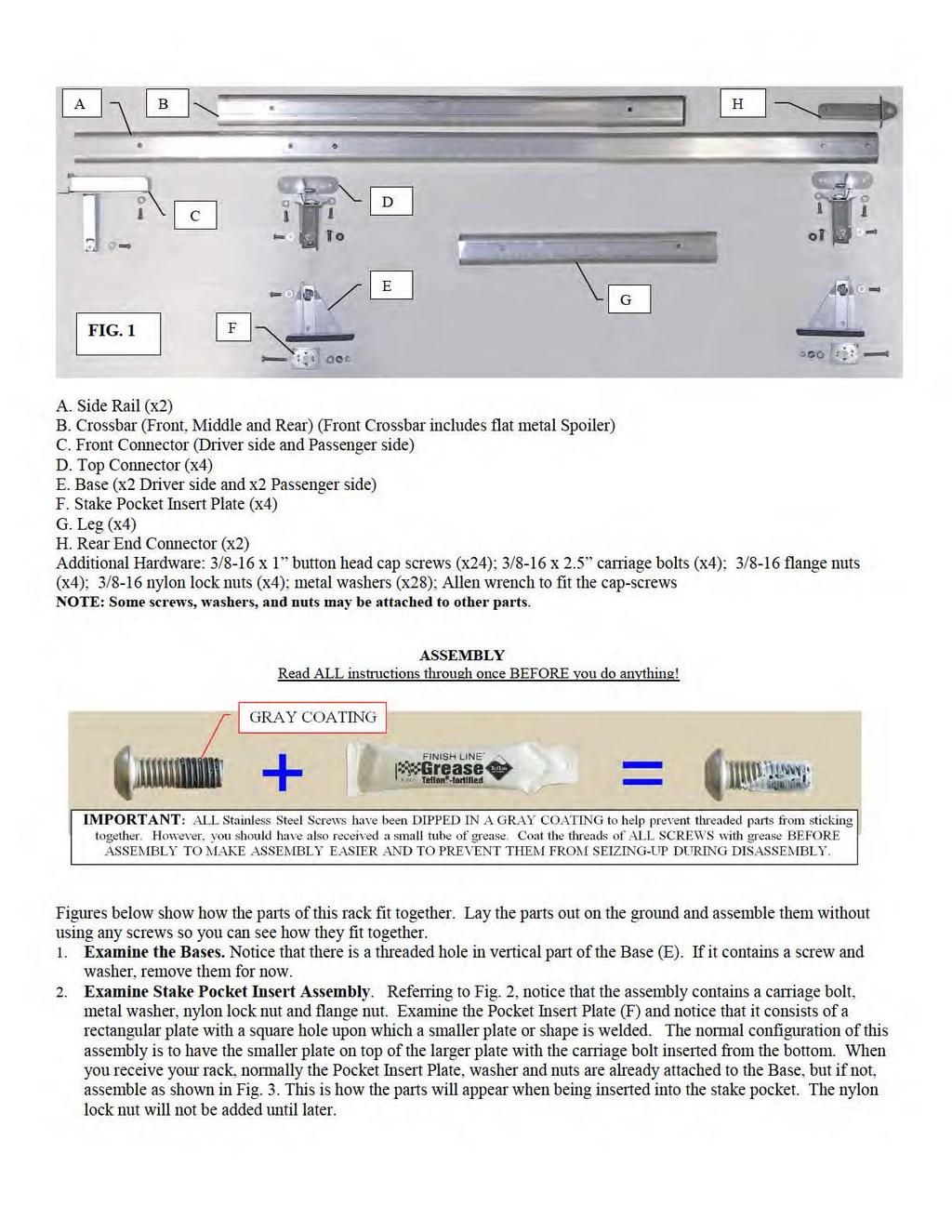
1 8MAY15 U.S. Rack Inc Falcon Drive, Madera, CA INSTRUCTION for GALLEON OVERHEAD STAKE POCKET RACK WARNING: Do NOT attempt to install or use this rack without following all instructions. SPECIFICATIONS and SAFE LOADING REQUIREMENTS The Galleon Overhead Stake Pocket Rack is intended to carry ladders and other cargo not exceeding 500 lbs and ONLY on pickup trucks with stake pockets. This rack is designed to carry loads, which are spread across the width of each crossbar and shared evenly between the three crossbars. It is not designed to carry loads where a force of over 100 lbs. is concentrated on any space less than 12 inches wide along any crossbar or where a force of over 200 lbs overall is loaded on either the rear or middle crossbar and where a force of over 100 lbs is loaded on the front crossbar. This product is not warranted for use off road or on unimproved or poorly maintained or bumpy roads, nor is warranted when used contrary to instructions or specified uses. U.S. Rack does NOT warrant any automotive product and does not warrant truck bed rails against damage or failures caused by the weight of excessive loads being applied to them when the rack is installed on a vehicle. U.S. Rack is not responsible for injury or property damage resulting from the rack being improperly installed or improperly loaded, nor is it responsible for injury or property damage resulting from loads or parts of loads falling or being blown off a vehicle. Loads extending beyond the rear bumper of the vehicle must be designated with a red flag during daylight or red light during darkness in accordance with the state vehicle code. Ensure that neither the rack nor any cargo blocks the view of tail or brake lights from rear. BE SAFE: Carrying any load can be hazardous. All loads must be tied down securely to the rack to prevent them from vibrating or sliding forward, backward, laterally or being blown off or broken by unexpected wind or road hazards such as potholes. Check each time you install the rack, load the rack, as well as daily to ensure that all connections are tight. Periodically check welds for cracking caused by metal fatigue. Avoid roll over by ensuring that loads are not top heavy. High loads must be transported with GREAT CAUTION to prevent loads from striking low overhead objects or tipping during turns, abrupt stops, or high winds. WARRANTY for the GALLEON RACK U.S. Rack products are warranted for a period of one year against all structural defects in materials and workmanship provided that they are assembled, installed, and used in accordance with all manufacturer s specifications and instructions. U.S. Rack cannot warrant the powder-coating on its products. Normal use of any powder-coated part and exposure to weather can result in scratching of the surface, exposing metal below; therefore, maintenance on your rack will be required. To prevent rust, spot paint any scratches or breaks in the surface with a high quality metal paint. Merchandize must be returned in the original box and packaging. See return policies and procedures at INVENTORY Your safety is paramount. Before assembling the rack, lay out all the parts. Inventory and inspect all parts. Visually check each part to ensure it corresponds to the inventory list and check all welds for signs of cracking or weakness. Manufacturing and shipping mistakes can happen. If you think you have received the wrong product for your model truck, if you do not have all the correct parts, or if any parts appear to be defective, STOP and do NOT install the rack. Contact customer service at to replace missing or defective parts. If you have any questions about installation, call customer service. Also, these instructions are NOT for Toyota Tundra s; they require some different parts.
2
3
4
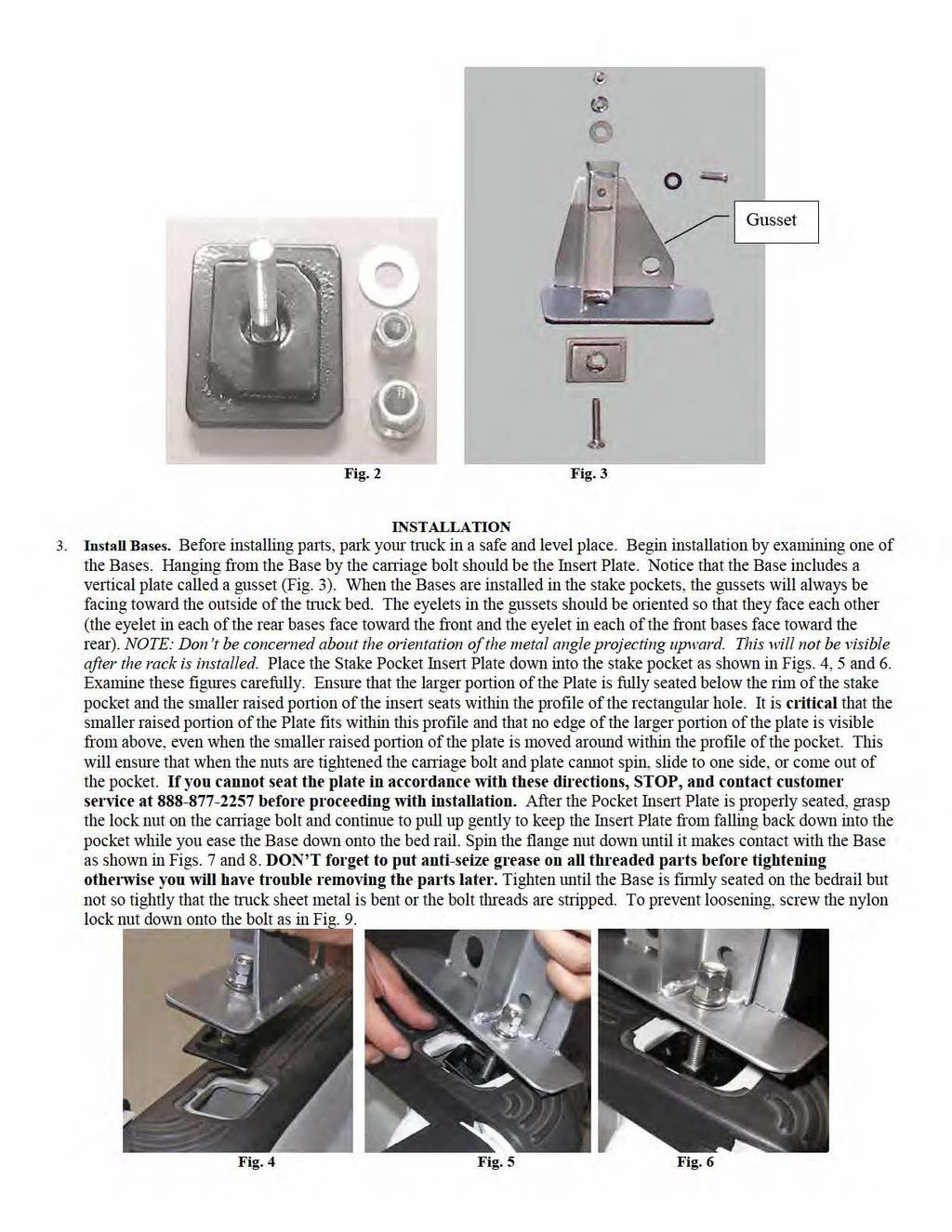
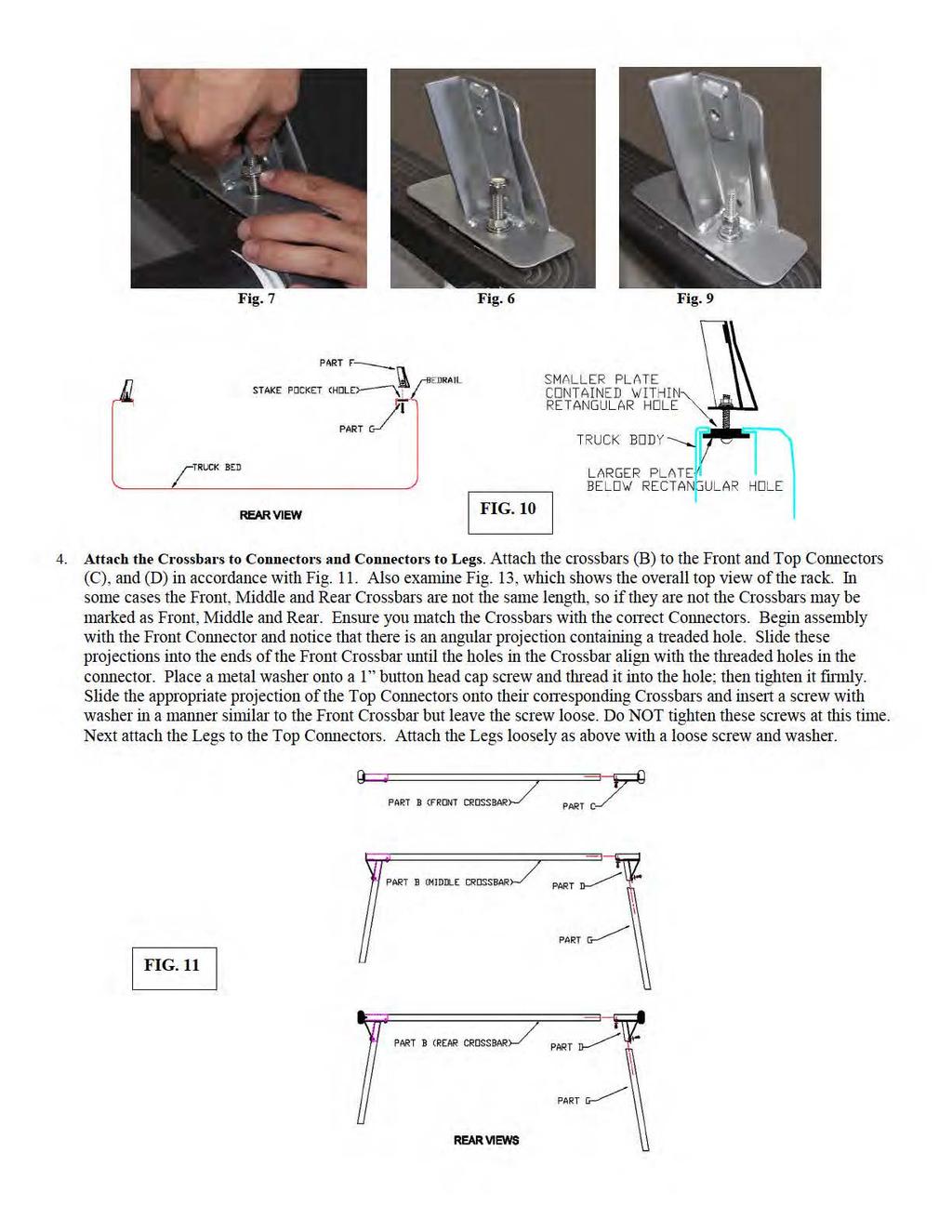
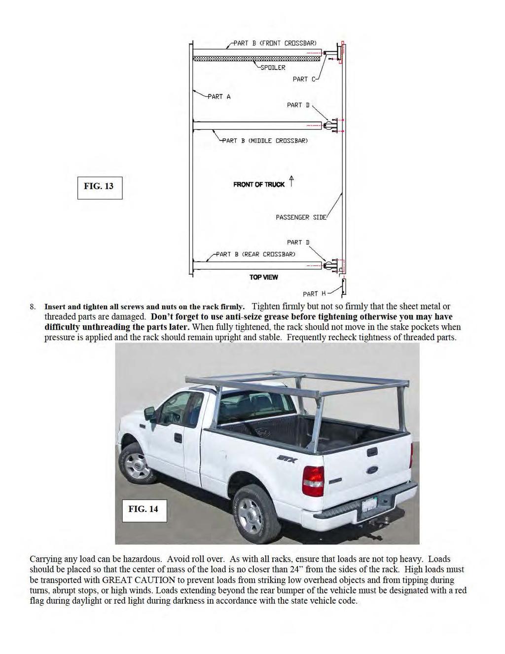
5 5. Attach the Crossbar/Leg Assemblies to the Bases. Examine Fig. 12, below. Lower the tailgate of your truck and step up inside with the Middle Crossbar/Leg assembly. Place the bottom of one Leg over the angular projection on the Base and slide it down until the hole in the bottom of the Leg aligns with the threaded hole in the Base. To do this, it will be necessary to tilt the Crossbar so that the Leg you are attaching is aligned with the projection on the Base. Next align the bottom of the other Leg with the other Base and attach similarly. Notice that since you have not tightened the screws in the Crossbar and Legs, there is flex in the assembly which allows you to roughly align the parts and complete the assembly. After the Legs and Bases are attached, insert screws with washers into the threaded holes. Now tighten ALL of the screws firmly with an Allen wrench, but not so firmly that you strip the threads or deform the parts. Attach the Rear Crossbar/Leg assembly in a similar manner. NOTE: In the event that you find it to difficult to flex the bottom of the second Leg onto the second Base, you may loosen one or both of the bases a little to allow them to move or tip to the appropriate angle for assembly. Then before seating the Leg all the way onto the base, leave enough space to re-tighten the nuts on the carriage bolt. FIG Attach Side Rails. Attach the Side Rails to the rear and middle crossbars as shown in Fig. 13. First hold one of the Side Rails (A) up against the Top Connector (D) so that the holes in the mid-section of the Side Rail align with the holes in the Top Connector. Insert a 1 button head cap screw with washer into one of the holes and tighten the Side Rail loosely to the Top Connector. Move to the rear Top Connector. Insert an End Connector into the hole in the end of the Side Rail so that the holes align. Now align the holes in the Top Connector with the holes in the Side Rail. Insert a 1 button head cap screw with washer into one of the holes and loosely tighten the Side Rail to the Top Connector. Attach the other Side Rail similarly and then add additional 1 screws and washers and tighten loosely. 7. Attach Front Crossbar Assembly. Attach the Front Connectors to the front of each Side Rail by aligning and inserting the projections of the connectors into the open hole at the end of each Side Rail. The Spoiler is a flat piece of aluminum that is designed to reduce wind noise. The crossbar should be oriented so that the spoiler is on the bottom of the crossbar and pointed toward the rear of the vehicle. Align the holes in the Front Connectors with the holes in the Side Rails. Thread a 1 screw as shown in Fig. 13 though the hole in the exterior portion of the front connector and tighten firmly.
6
9MAY15 U.S. RACK, Inc Falcon Drive, Madera, CA
 9MAY15 U.S. RACK, Inc. - 2850 Falcon Drive, Madera, CA 93637-559-661-3050 INSTRUCTIONS for the V-RACK WARNING: Do NOT attempt to install or use this rack without following all instructions. SPECIFICATIONS
INSTRUCTIONS for STAKE POCKET RACK WARNING: Do NOT attempt to install or use this rack without following all instructions.
 28SP11 U.S. Rack Inc. 2850 Falcon Drive, Madera, CA 93637 1 888 877 2257 INSTRUCTINS for STAK PCKT RACK WARNING: Do NT attempt to install or use this rack without following all instructions. SPCIFICATINS
US RACK, Inc Falcon Drive, Madera, CA
 US RACK, Inc - 2850 Falcon Drive, Madera, CA 93637-559-661-3050 INSTALLATION AND USE INSTRUCTIONS for Long-John Extension Ladder Rack WARNING: Do NOT attempt to install or use this rack without following
U.S. Rack, Inc Falcon Drive, Madera, CA APR17 INSTALLATION AND USE INSTRUCTIONS for SIDE-MOUNT LADDER RACK
 U.S. Rack, Inc. 2850 Falcon Drive, Madera, CA 93637 15APR17 INSTALLATION AND USE INSTRUCTIONS for SIDE-MOUNT LADDER RACK WARNING: Do NOT attempt to install or use this rack without following all instructions.
INSTRUCTIONS for WOODY RACK ON STANDARD FLEETSIDE TRUCKS WARNING: Do NOT attempt to install or use this rack without following all instructions.
 8JUL15 U.S. RACK, Inc. - 2850 Falcon Drive, Madera, CA 93637-559-661-3050 INSTRUCTIONS for WOODY RACK ON STANDARD FLEETSIDE TRUCKS WARNING: Do NOT attempt to install or use this rack without following
17MAY18 U.S. RACK, Inc Falcon Drive, Madera, CA
 17MAY18 U.S. RACK, Inc. - 2850 Falcon Drive, Madera, CA 93637-559-661-3050 INSTRUCTIONS for FIFTH WHEEL RACK Model 2010-4AD WARNING: Do NOT attempt to install or use this rack without following all instructions.
27APR18 U.S. RACK, Inc Falcon Drive, Madera, CA
 27APR18 U.S. RACK, Inc. - 2850 Falcon Drive, Madera, CA 93637-559-661-3050 INSTRUCTIONS for FIFTH WHEEL RACK Model 2010-4ADC WARNING: Do NOT attempt to install or use this rack without following all instructions.
U.S. RACK, Inc Falcon Drive, Madera, CA
 U.S. RACK, Inc. - 2850 Falcon Drive, Madera, CA 93637-559-661-3050 INSTRUCTIONS for FIFTH WHEEL RACK Models 2010-4ADC and 2010-4ADCD WARNING: Do NOT attempt to install or use this rack without following
US RACK, Inc Falcon Drive, Madera, CA
 US RACK, Inc. - 2850 Falcon Drive, Madera, CA 93637-559-661-3050 INSTRUCTIONS for MOTORCYCLE RACK with Cradling Wheel Chocks WARNING: Do NOT attempt to install or use this rack without following all instructions.
Contractors Rack Assembly and Installation Instructions
 Part # 18601 & 16601 Contractors Rack Assembly and Installation Instructions 4751 Littlejohn St. Unit A, Baldwin Park, CA 91706 Page 1 of 12 11/13/08 Thank you for purchasing the Paramount Restyling Contractors
PRORAC CONTRACTOR SERIES UNIVERSIAL STEEL TRUCK / CAP RACK INSTALLATION INSTRUCTIONS
 PRORAC CONTRACTOR SERIES UNIVERSIAL STEEL TRUCK / CAP RACK INSTALLATION INSTRUCTIONS 1000 Lb. Capacity Bed Mount 750 Lb. Capacity Cap Mount Package Contents: Parts Hardware (4) Legs (12) 3/8-16 x 1-1/4
M ACS Instructions
 APPLICABLE MODELS: Nissan Frontier 2005 and up short bed with Utili-Trak mounting rails PACKAGE CONTENTS 00-0060-M-01-1205 ACS Instructions Leitner Designs 25675 Taladro Circle Unit E Mission Viejo, CA
Check us out on-line! Installation Instructions
 Installation Instructions 2 OPTIONAL ACCESSORIES Order Quantum Rack Accessories Online at www.dawsbetterbuilt.com Cargo Lock Kit Secure Your Load Cargo Locks can easily be installed and adjusted left or
Sunset Swings By Health in Motion, LLC
 Sunset Swings By Health in Motion, LLC Model 421 Lounge Swing Assembly and Operation Manual Record Serial Number Here www.sunsetswings.com by Health In Motion, LLC. 11/6/2009 421 Owners Assembly and Operation
FOLDING TONNEAU RACK. 1. Rack Rail Assembly
 FOLDING TONNEAU RACK Package Contents (2) Load Bars (4) Load Bar End Caps (4) ¼-20 x 9/16 Narrow Shoulder Hex Head Screw (28) ¼ Flat Washers (24) ¼ Split Lock Washers (20) ¼-20 x ¾ long Button Head Screws
ASSEMBLY INSTRUCTIONS FOR HAULER II UNIVERSAL CAMPER SERIES RACKS
 ASSEMBLY INSTRUCTIONS FOR HAULER II UNIVERSAL CAMPER SERIES RACKS C11U2873-1 shown above Package Contents: HARDWARE KIT PARTS (4) 3/8-16 x 3 CARRAIGE BOLTS (1) RAIL DRIVER S SIDE ASSEMBLY (20) 3/8-16 x
HONDA RIDGELINE (KIT #601) Installation Instructions (to be used in addition to owners manual)
 Installation Instructions (to be used in addition to owners manual)") HONDA RIDGELINE (KIT #601) Installation Instructions (to be used in addition to owners manual) IMPORTANT NOTE: Read before beginning installation. These instructions replace all of Step 1 of the instructions
HONDA RIDGELINE (KIT #601) Installation Instructions (to be used in addition to owners manual) IMPORTANT NOTE: Read before beginning installation. These instructions replace all of Step 1 of the instructions
ASSEMBLY INSTRUCTIONS FOR T-10, T-11 & T-12 SERIES RACKS
 ASSEMBLY INSTRUCTIONS FOR T-10, T-11 & T-12 SERIES RACKS T12SHD-1 with 26 Legs shown above. Package Contents: HARDWARE KIT PARTS (8) 3/8-16 x 3 CARRAIGE BOLTS (1) RAIL DRIVER S SIDE ASSEMBLIES (20) 3/8-16
PLANISHING HAMMER STAND OWNER S MANUAL
 PLANISHING HAMMER STAND OWNER S MANUAL WARNING: Read carefully and understand all INSTRUCTIONS before operating. Failure to follow the safety rules and other basic safety precautions may result in serious
INSTALLATION MANUAL WEEKENDER STEEL LADDER RACK
 TRUCK STORAGE SOLUTIONS SECURING YOUR REPUTATION INSTALLATION MANUAL WEEKENDER STEEL LADDER RACK STEEL & ALUMINUM SIDE BOX WITH PACK RAT DRAWER UNITS MODELS ATTENTION: PLEASE READ AND UNDERSTAND ALL INSTRUCTIONS
OPERATORS MANUAL WEEKENDER STEEL LADDER RACK
 OPERATORS MANUAL WEEKENDER STEEL LADDER RACK WWW.WEATHERGUARD.COM MODELS 1450 & 1475 1475 Shown INSTALLATION TIME Approximate installation time: 60 minutes (depending on truck equipment installation experience
Cottage Style Dock Instructions
 Cottage Style Dock Instructions Table of Contents 1. Dock Assembly and Set-Up 1.1 Quick Start 1.2 Positioning Quick Clips 1.3 Installing Dock Legs 1.4 Installing Foot Pads 1.5 Installing Cross Braces 1.6
Pickup Box Utility Rack Package Installation (Instruction ID: )
") 017 Chevrolet Colorado Pickup - WD (VIN S) Canyon, Colorado Accessory Installation Manual N America Document ID: 3966961 Pickup Box Utility Rack Package Installation (Instruction ID:3144879) Installation
017 Chevrolet Colorado Pickup - WD (VIN S) Canyon, Colorado Accessory Installation Manual N America Document ID: 3966961 Pickup Box Utility Rack Package Installation (Instruction ID:3144879) Installation
400A 40113V, 401A 40120V, & 401AL 40120VL ALUMINUM VERTICAL 4000 LB LIFT INCLUDES SCREW LEG ASSEMBLY INSTRUCTIONS
 12/11/07 PAGE 1 OF 12 400A 40113V, 401A 40120V, & 401AL 40120VL ALUMINUM VERTICAL 4000 LB LIFT INCLUDES SCREW LEG ASSEMBLY INSTRUCTIONS Thank you for purchasing our product! *Please read these instructions
SAFETY THIS PRODUCT IS FOR OFFROAD USE ONLY. ALL LIABILITY FOR INSTALLATION AND USE RESTS WITH THE OWNER.
 SAFETY Your safety and the safety of others is very important. In order to help you make informed decisions about safety, we have provided installation instructions and other information. These instructions
INSTALLATION MANUAL FRONT. See pages 2 and 3 of this manual for configuration options. Level of Difficulty. Product Photo (center section only)
") INSTALLATION MANUAL FRONT Level of Difficulty Moderate Product Photo (center section only) All hardware listed below will be provided with the bumpers center section. Additional hardware will be supplied
INSTALLATION MANUAL FRONT Level of Difficulty Moderate Product Photo (center section only) All hardware listed below will be provided with the bumpers center section. Additional hardware will be supplied
ASSEMBLY INSTRUCTIONS FOR SERVICE BODY A MOUNT RACKS
 ASSEMBLY INSTRUCTIONS FOR SERVICE BODY A MOUNT RACKS T12 Service Body A shown with optional middle crossbar Package Contents: HARDWARE KIT PARTS (8) 3/8-16 x 3 CARRAIGE BOLTS (1) RAIL DRIVER S SIDE ASSEMBLIES
This manual will aid in the assembly of the FireBall V90 and FireBall X90. The assembly of both machines will be identical, unless specified.
 This manual will aid in the assembly of the FireBall V90 and FireBall X90. The assembly of both machines will be identical, unless specified. Step #1 Lay all parts out to verify quantities. (2) 2 x 25-1/4
Assembly Instructions for model: VMPR1
 Assembly Instructions for model: VMPR1 Congratulations on your purchase! The VMPR1 ceiling mount provides a unique, simplified method of ceiling mounting inverted LCD/DLP projectors. Its low profile design
4-Door EXO-Top Roof Rack System
 Page 1/31 4-Door EXO-Top Roof Rack System 13516.02! WARNING The EXO-Top Roof Rack System is rated to a dynamic 300 lb, evenly distributed load. Further loading could result in serious injury or death.
WEAR SAFETY GLASSES WHEN INSTALLING THIS KIT.
 INSTALLATION INSTRUCTIONS Trans4mer Mounting Systems Part No. 29753 (black) Part No. 65654 (stainless) for full size GM pickups, and Blazer, Yukon, Suburban, Tahoe As you read these instructions, you will
BISON GOOSENECK FOOTBALL 1 PAIR OF GOAL POSTS
 Instruction Manual BISON GOOSENECK FOOTBALL 1 PAIR OF GOAL POSTS Customer Service (800) 247-7668 P A R T S L I S T Item Qty Description Item Qty Description A 2 GOOSENECK POLE I 4 UPRIGHTS B 2 BAND CLAMP
TOYOTA TUNDRA CARGO DIVIDER Preparation. Part Number: PT
 Preparation Part Number: PT767-34070 Kit Contents 1 1 Divider Screen 2 1 LH Bracket with Warning Label 3 1 RH Bracket without Warning Label NOTE: Part number of this accessory may not be the same as the
Hip Roof Canopy Instructions
 Hip Roof Canopy Instructions - PUT SAFETY FIRST. NOT COMPLYING WITH THE PROCEDURES AND PRECAUTIONS OUTLINED IN THIS MANUAL MAY RESULT IN PERSONAL INJURY AND WILL INVALIDATE THE WARRANTY.. Before attempting
Installation Instructions BestRail Ladder Rack Must be used with BestRail Accessories: Overhead Rack
 Installation Instructions BestRail Ladder Rack Must be used with Accessories: 42791 Can be used with Accessories: 42793 Tie Down 42794 Retractable Tie Down The channels in the Ladder Rack are the same
ASSEMBLY INSTRUCTIONS for : G Trade Center Drive Rancho Cordova, CA DON'T OVERLOAD YOUR VEHICLE! 100" = 3 X lbs. 35" = X lbs.
 ASSEMBLY ISTRUCTIOS for : PRO-III& IV (916) 638-8703 (800) 343-7486 11253- G Trade Center Drive Rancho Cordova, CA 95742 DO'T OVERLOAD YOUR VEHICLE! LBS. @ 100" = 3 X lbs. OVERTUR FORCE LBS. @ 35" = X
User Instructions Multiline Otter Scoreboard Caddy Assembly
 List of parts: User Instructions Multiline Otter Scoreboard Caddy Assembly Single Caddy Double Caddy 1 1 Base assembly with attached wheels 2 4 1 1 2 4 4 8 10 20 12 Uprights (60 or 74 aluminum extrusion)
O-Sullivan King 4 Poster Bed O-Sullivan Queen 4 Poster Bed Parts and Hardware List
 Parts and Hardware List A. Left Headboard Post 1 pc B. Right Headboard Post 1 pc C. Left Footboard Post 1 pc D. Right Footboard Post 1 pc E. Headboard Panel 1 pc F. Footboard Rail 1 pc. Spindles 4 pcs
INSTALLATION MANUAL PACK RAT DRAWER UNITS MODELS NOTICE WARNING DANGER CAUTION
 TRUCK STORAGE SOLUTIONS SECURING YOUR REPUTATION INSTALLATION MANUAL ALUMINUM STEEL & ALUMINUM & STEEL SIDE HI-SIDE/SUPER-SIDE BOX WITH BOX PACK RAT DRAWER UNITS MODELS ATTENTION: PLEASE READ AND UNDERSTAND
Please read and understand the OnBoard Timpani Cart Owner s Manual before using the Timpani Cart.
 Assembly and Owner s Manual OnBoard Timpani Cart Performance Position Towing Position CONTENTS Important User Information...........................2 General......................................2 Manufacturer.................................2
Thank you for purchasing our product! *Please read these instructions and follow them step by step.*
 07/07/08.rev1 PAGE 1 OF 11 601AL VERTICAL 60120VL LIFT W/CHAIN DRIVE WINCH Thank you for purchasing our product! *Please read these instructions and follow them step by step.* Step 1. Separate and group
Medium HoneyBadger Chase Rack Installation Instructions
 PREPARATION Medium HoneyBadger Chase Rack Installation Instructions 1. Disconnect the negative terminal on the battery. Park the vehicle on level ground and set the emergency brake. 2. We recommend reading
MERRY GO ROUND ITEM NO: 8030
 MERRY GO ROUND ITEM NO: 8030 OWNER S MANUAL CAUTION: This unit is designed to be used safely by up to 4 children between the ages of 3 years to 8 years old with a maximum weight of 00 pounds (45.4 kgs)
PRO - III & IV K M K N H A D J M J 1/2", 9/16", & 3/4" 2004 KargoMaster-'Pro 3' _2.1. com
 PRO - III & IV B L G M D E M 4 2 F 1 F L H D C 3 H A 8 M 7 1/2", 9/16", & 3/4" drawitforyou com 2004 argomaster-'pro 3' _2.1 A (4 ea.) 1/2" x 3 1/2" Hex Bolt B (2 ea.) 1/2" x 2 1/4" Button Head Bolt C
2-Door EXO-Top Roof Rack System
 Page 1/29 Part 13516.01 2-Door EXO-Top Roof Rack System! WARNING The EXO-Top Roof Rack System is rated to a dynamic 300 lb, evenly distributed load. Further loading could result in serious injury or death.
Installation Manual Roof Zone Ladder Rack
 Installation Manual Roof Zone Ladder Rack 102113,E1346 Installation Time: About 90 minutes. Depending on truck and Do-it-Yourself experience level Tools Required: Electric Drill with 1/2 Chuck 1/2 & 7/32
MPA-9000 Universal Ceiling Projector Mount Kit
 I N S T R U C T I O N M A N U A L Universal Ceiling Projector Mount Kit The Universal Ceiling Projector Mount provides a unique, simplified method of ceiling mounting your inverted projector. This low
ASSEMBLY INSTRUCTIONS FOR HAULER II SERVICE BODY A RACK
 ASSEMBLY INSTRUCTIONS FOR HAULER II SERVICE BODY A RACK T12USBA-1 shown above Package Contents: HARDWARE KIT PARTS (4) 3/8-16 x 3 CARRAIGE BOLTS (1) RAIL DRIVER S SIDE ASSEMBLY (20) 3/8-16 x 2 CARRAIGE
Aluminum Lake Truss Dock Instructions
 Table of Contents Aluminum Lake Truss Dock Instructions 1. Dock Assembly and Set-Up 1.1 Quick Start 1.2 Positioning Quick Clips 1.3 Installing Dock Legs 1.4 Installing Foot Pads 1.5 Installing Cross Braces
INSTALLATION INSTRUCTIONS UTV LIGHT BAR KIT Part Number: and Application: All UTV s*
 INSTALLATION INSTRUCTIONS UTV LIGHT BAR KIT Part Number: 83970 and 84360 Application: All UTV s* * does not include Arctic Cat vehicles Your safety, and the safety of others, is very important. To help
Installation Manual. SKU# TracVan Double SKU# TracVan Double SKU# TracVan Triple
 Installation Manual SKU# 29054 TracVan Double SKU# 29055 TracVan Double SKU# 29056 TracVan Triple TRACVAN INSTALLATION INSTRUCTIONS SKU# 29054, 29055 & 29056 TracVan installation is straightforward, and
Desk/Wall-Mount Rack
 Desk/Wall-Mount Rack Patent(s) Pending Installation Instructions Post P/N: 119-1752 119-1781 119-1782 119-4014 Frame P/N: 119-1591 119-1754 119-1755 Kit Contents (2) Frames (4) Posts Assembly Hardware
INSTALLATION MANUAL WEEKENDER STEEL LADDER RACK
 TRUCK STORAGE SOLUTIONS SECURING YOUR REPUTATION INSTALLATION MANUAL WEEKENDER STEEL LADDER RACK STEEL & ALUMINUM SIDE BOX WITH PACK RAT DRAWER UNITS MODELS ATTENTION: PLEASE READ AND UNDERSTAND ALL INSTRUCTIONS
Assembly Instructions Signature Choral Riser 4-Step Model
 Assembly Instructions Signature Choral Riser 4-Step Model Contents Important User Information...........................2 General...2 Manufacturer...2 Intended Use...2 Warranty...2 Safety Precautions.................................3
N. 15th Street, Middlesboro, KY FLIP TARP DUMP BODY INSTALLATION INSTRUCTIONS
 1-800-248-7717 1002 N. 15th Street, Middlesboro, KY 40965 FLIP TARP DUMP BODY INSTALLATION INSTRUCTIONS Congratulations on your purchase of a Mountain Flip Tarp Dump Body tarping system. With tarping systems
FLIP TARP SINGLE & DOUBLE UNDERBODY TRAILERS
 1-800-248-7717 1002 N. 15th Street, Middlesboro, KY 40965 FLIP TARP SINGLE & DOUBLE UNDERBODY TRAILERS INSTALLATION INSTRUCTIONS Congratulations on your purchase of a Mountain Flip Tarp Trailer system.
ALUMINUM HEADKNOCKER RACK P/N HKRS4-1 / HKRS5-1
 ALUMINUM HEADKNOCKER RACK P/N HKRS4-1 / HKRS5-1 Package Contents: PARTS (1) CROSS BAR (2) LEGS WITH FEET (2) T BRACKETS (1) SCREEN ASSEMBLY (2) SCREEN L MOUNTS (2) LOWER SCREEN MOUNTS (2) LOAD SECURE POSTS
Continuum Frame Assembly Instructions
 Continuum Frame Assembly Instructions Copyright January 1, 2017 Jim M. Bagley, GraceWood, Inc (Reproduction Prohibited) Version 2.2 Table of Contents Continuum Frame Table of Contents... i Warranty...ii
Heavy Duty Ceiling Tilt Mount Installation Manual
 HD-CTM-5580 Heavy Duty Ceiling Tilt Mount Installation Manual *This Installation requires a minimum of two people. For your safety: Read the complete instruction manual before starting an installation
Hollywood Swing Away 2 and 4 Bike Racks Assembly and Installation Guide
 Hollywood Swing Away 2 and 4 Bike Racks Assembly and Installation Guide Tools Required: two adjustable wrenches, pliers, ¾ socket wrench recommended Note: please do assembly near your vehicle as you Can
x16 GAZEBO ASSEMBLY INSTRUCTIONS
 36 1 x16 GAZEBO ASSEMBLY INSTRUCTIONS Assembly with more than one person recommended 0 L:\WP51\Instructions\SOLARIUMS INSTRUCTION BOOKS\36\ZZZ-05.36.0810-1.GP.EN.doc Step 1: Assemble beams A and B using
INSTALLATION INSTRUCTIONS
 INSTALLATION INSTRUCTIONS R5 STEP BOARD APPLICATION: 2009-2017 Dodge Ram 1500 Quad / Crew Cab 2010-2017 Dodge Ram 2500/3500 Crew Cab PART NUMBER: 28-51040, 28-51045, 28-51050, 28-51055 ITEM QUANTITY DESCRIPTION
Roof Rack Installation Instructions
 Roof Rack Installation Instructions CAUTION: Do not use the mounting hardware contained in this roof rack kit for installation on Fiberglass or Composite Plastic surfaces. Supplemental hardware pack, part#
MM750 Installation Instructions
 MM750 Installation Instructions IMPORTANT SAFETY INSTRUCTIONS - SAVE THESE INSTRUCTIONS Please read this entire manual before you begin. Do not unpack any contents until you verify all requirements on
SAFETY THIS PRODUCT IS FOR OFFROAD USE ONLY. ALL LIABILITY FOR INSTALLATION AND USE RESTS WITH THE OWNER.
 SAFETY Your safety and the safety of others is very important. In order to help you make informed decisions about safety, we have provided installation instructions and other information. These instructions
MODULAR BUMPER INSTALLATION MANUAL
 MODULAR BUMPER INSTALLATION MANUAL Parts List* 1 Center section 1 Side extension, passenger / right 1 Side extension, driver / left 1 Side cap, passenger / right 1 Side cap, driver / left 1 Brush guard,
ASSEMBLY AND INSTALLATION INSTRUCTIONS
 ASSEMBLY AND INSTALLATION INSTRUCTIONS Model 1425 Aluminum Swivel Rack IMPORTANT BEFORE YOU BEGIN Read these instructions and warnings completely before installation. CAPACITY 200 lbs. MAXIMUM NOTE: This
CAB END BEDTRAX (SIDE VIEW)
") Supplied Hardware: (8-14) 1/4-20 Allen head bolts, (12-18) UHMW mount blocks, (4) D-ring tie downs Tools Needed: Allen head wrench GET TO IT. INSTALLATION INSTRUCTIONS STEP 1. INSERT (2) MOUNT BLOCKS INTO
Supplied Hardware: (8-14) 1/4-20 Allen head bolts, (12-18) UHMW mount blocks, (4) D-ring tie downs Tools Needed: Allen head wrench GET TO IT. INSTALLATION INSTRUCTIONS STEP 1. INSERT (2) MOUNT BLOCKS INTO
Side-of-Pole Mount for 4 Modules (SPM4) For Module Type B ASSEMBLY INSTRUCTIONS. step-by-step assembly and installation
 For Module Type B ASSEMBLY INSTRUCTIONS. step-by-step assembly and installation") Side-of-Pole Mount for 4 Modules (SPM4) For Module Type B ASSEMBLY INSTRUCTIONS step-by-step assembly and installation Version 1, Rev A SP3358-2 PCN 060712-5 Side-of-Pole Mount for 4 Modules (SPM4) For
Side-of-Pole Mount for 4 Modules (SPM4) For Module Type B ASSEMBLY INSTRUCTIONS step-by-step assembly and installation Version 1, Rev A SP3358-2 PCN 060712-5 Side-of-Pole Mount for 4 Modules (SPM4) For
Phone # La Jolla Doors. Block Frame Installation Manual Aluminum Frame with either Vinyl or Aluminum Panels
 Phone # 800-440-8785 www.lajolladoors.com La Jolla Doors Block Frame Installation Manual Aluminum Frame with either Vinyl or Aluminum Panels Thank you for choosing La Jolla Doors In this manual you will
INSTALLATION INSTRUCTIONS MAIN BAR TIPO B 90002, 91002, 91502, 92002, 93002, 94002, 95002, 96002, y PS / B / C
 Parts List: i) 4-7/16" Plastic cap Not Includes: a) 1- Driver Leg 8-3/8x1 1/2" Flat washer Kicker b) 1- Passenger Leg 8-3/8" Hex nut c) 1- Cross bar 4-3/8x 1 1/2" Carriage bolt d) 2- Mounting plate 4-3/8x
Electric Skein Winder
 Electric Skein Winder Assembly and Use Package Contents 1 - Triangular Body (w/ motor) 1 - Cross Arm 1 - Left Foot (w/ yarn guide) 1 - Right Foot 1 - Adjustable Finger (w/ yarn clip) 3 - Adjustable Fingers
Installation Instructions Jeep JL Front Grumper Product Number: GR4600 Application: 18+ JEEP JL
 ! IMPORTANT SAFETY GUIDE Your safety and the safety of others is very important. In order to help you make informed decisions about safety, we have provided the following warnings, safety precautions,
Classic Roll Tarp. Installation Instructions. Attention Dealers: Please give this owners manual to the customer when the product is delivered.
 Serving the Truck & Trailer Industry Since 1944 Classic Roll Tarp Attention Dealers: Please give this owners manual to the customer when the product is delivered. Call 800-535-9545 www.aeroindustries.com
Sunrise Deck Assembly Instructions for Kingston Left
 Sunrise Deck Assembly Instructions for Kingston Left It s easiest to build the deck frame first like it will be lying on its back and then after all 4 legs and horizontals are in place, tip the deck toward
Classic Roll Tarp. Installation Instructions. Attention Dealers: Please give this owners manual to the customer when the product is delivered.
 Serving the Truck & Trailer Industry Since 1944 Classic Roll Tarp Attention Dealers: Please give this owners manual to the customer when the product is delivered. Call 800-535-9545 www.aeroindustries.com
INSTALL INSTRUCTIONS WELCOME TO THE NEWAGE PERFORMANCE CABINETRY SERIES NEWAGE STEEL WELDED CABINETRY
 NEWAGE STEEL WELDED CABINETRY WELCOME TO THE NEWAGE PERFORMANCE CABINETRY SERIES ALL CABINETS MUST BE MOUNTED TO STUDS ON A SECURE WALL, AS PER THESE INSTRUCTIONS. FAILURE TO DO SO MAY RESULT IN SERIOUS
Outdoor Water Solutions, Inc. Small Backyard Windmill. Installation Manual
 Outdoor Water Solutions, Inc. Small Backyard Windmill Installation Manual Customer Service: 1-866-471-1614 Website: www.outdoorwatersolutions.com Springdale, Arkansas 72764 Phone: 1-866-471-1614 Fax: 1-479-750-9178
installation guide 1 GUIDE#: pwb-assault-001
 assault WAKEBOARD tower installation guide INSTALLATION SUPPORT 1 important information This Aerial wakeboard tower fits motor boats with 76-108 inch wide beam widths. This measurement is taken from the
PAN AND BOX BRAKE INSTRUCTIONS. Item #20649
 PAN AND BOX BRAKE INSTRUCTIONS Item #20649 The EASTWOOD 12 & 24 PAN AND BOX BRAKES are precision engineered metal working tools designed to produce accurate, variable length bends in angles up to 135 in
Signature Choral Riser Side Rail
 Assembly/Owner s Manual Signature Choral Riser Side Rail Signature Choral 3-Step Riser with Optional Side Rail Signature Choral 4-Step Riser with Optional Side Rail CONTENTS Visit the Signature Choral
IN-30000_F. Installation Instructions
 IN-30000_F Installation Instructions Parts Overview Detail A Detail B Detail C Detail A Detail C Detail B Parts List & Tools PARTS ITEM NO. PART NUMBER DESCRIPTION Qty 1 01-30008-01 P/C,DOUBLE T-SLOT CROSSBAR,
OPERATOR'S MANUAL 46" SNOW BLADE. Model Numbers OEM IMPORTANT: READ SAFETY RULES AND INSTRUCTIONS CAREFULLY
 OPERATOR'S MANUAL 46" SNOW BLADE Model Numbers 190-833-OEM IMPORTANT: READ SAFETY RULES AND INSTRUCTIONS CAREFULLY MTD PRODUCTS INC. P.O. BOX 368022 CLEVELAND, OHIO 44136-9722 PRINTED IN U.S.A. FORM NO.
Installation Instructions
 IN-30000_F Installation Instructions TracRac Inc. 994 Jefferson St. FallRiver MA 02721 www.tracrac.com 800-501-1587 Thank you for your purchase of a T-Rac G2 cargo rack from TracRac. TracRac takes great
x12 GAZEBO ASSEMBLY INSTRUCTIONS
 30 10 x1 GAZEBO ASSEMBLY INSTRUCTIONS Assembly with more than one person recommended 0 L:\WP51\Instructions\SOLARIUMS INSTRUCTION BOOKS\30\ZZZ-0.30.0807-1.GP.EN.doc Step 1: Assemble beams A and B using
SUMMERHOUSE PERGOLA ASSEMBLY INSTRUCTIONS. Toll-free: MODEL NO
 SUMMERHOUSE PERGOLA MODEL NO. 088-1759-2 INSTRUCTIONS Toll-free: 1-888-670-6684 IMPORTANT: Please read this manual carefully before beginning assembly of this product. Keep this manual for future reference.
Assembly Instructions and Owner s Manual Flex TechBridge
 Assembly Instructions and Owner s Manual Flex TechBridge Contents Important User Information...........................2 Safety Precautions.................................2 Required Tools.....................................3
(B1 - B3) ASSEMBLY INSTRUCTIONS COASTER FINE FURNITURE TWIN / TWIN BUNKBED
 ASSEMBLY INSTRUCTIONS COASTER FINE FURNITURE TWIN / TWIN BUNKBED") 460136 (B1 - B3) TWIN / TWIN BUNKBED COASTER FINE FURNITURE PAGE 1 OF 8 REVISION 0: 06/10/2010 REVISION 1: 07/03/2013 ITEM : 460136 (B1 - B3) ASSEMBLY TIPS: 1. Remove hardware from box and sort by size
460136 (B1 - B3) TWIN / TWIN BUNKBED COASTER FINE FURNITURE PAGE 1 OF 8 REVISION 0: 06/10/2010 REVISION 1: 07/03/2013 ITEM : 460136 (B1 - B3) ASSEMBLY TIPS: 1. Remove hardware from box and sort by size
15 Planer Stand. Model Due to continuing improvements, actual product may differ slightly from the product described herein.
 15 Planer Stand Model 96316 Assembly And Operation Instructions Due to continuing improvements, actual product may differ slightly from the product described herein. 3491 Mission Oaks Blvd., Camarillo,
Install Instructions. NewAge Steel Welded Tall Locker
 Kit Contains Full Width Adjustable Steel Shelves (4) Height-Adjustable Steel Leveling Legs (4) Aluminum Door Trim (2) 2.5 x ¼ Cabinet Mounting Lag Bolts (4) Large Zinc Plated Mounting Washers (4) 5/8 x
3,500/4,500lb. Vertical Cable Feighner Lift
 3,500/4,500lb. Vertical Cable Feighner Lift CAUTION - PUT SAFETY FIRST 1. Before attempting to install or operate this lift, study and fully understand the proper operating procedures and safety precautions
Installation Manual Tilt Leg
 Installation Manual Tilt Leg Solar Mounting Solutions March www.ironridge.com 2010 IronRidge, Inc. All Rights Reserved Version 2.0 2 Tilt Leg Installation Guide Introduction The Tilt Leg is a flexible
Kwik-Lock. Installation Instructions. Attention Dealers: Please give this owners manual to the customer when the product is delivered.
 Serving the Truck & Trailer Industry Since 1944 Installation Instructions Attention Dealers: Please give this owners manual to the customer when the product is delivered. Call 800-535-9545 www.aeroindustries.com
Product Information. Brass & Cast Bedsteads
 Product Information Brass & Cast Bedsteads parts CheCk list 4 0,4 6,5 0,6 0 slatted FraMe 01 headend 1 02 Footend 1 03 head end extension legs 2 04 side rails 2 05 end cross bar 2 06 Center cross bar 1
JEEP JK ( 5 DOOR ) SLIMLINE II - FULL TRAY EXTREME RACK KIT
 SLIMLINE II - FULL TRAY EXTREME RACK KIT") JEEP JK ( 5 DOOR ) SLIMLINE II - FULL TRAY EXTREME RACK KIT FAJK001 / KRJW014T INSTALL TIME: 2.5 Hours NOTE: Your Jeep JK (5 Door) Extreme Roof Rack Kit consists of four boxes. (1) the Tray, (2) the Roll
JEEP JK ( 5 DOOR ) SLIMLINE II - FULL TRAY EXTREME RACK KIT FAJK001 / KRJW014T INSTALL TIME: 2.5 Hours NOTE: Your Jeep JK (5 Door) Extreme Roof Rack Kit consists of four boxes. (1) the Tray, (2) the Roll
SAM. Model: STV-C65 LCD Mobile Visualized Stand Instruction Manual. Weight Capacity: 1251bs / 56.7kg Suits LCD Flat Panel Display: 42"-55" Page 20
 SAM Model: STV-C65 LCD Mobile Visualized Stand Instruction Manual Weight Capacity: 1251bs / 56.7kg Suits LCD Flat Panel Display: 42"-55" 20 Step 6 LCD Mobile Lift Stand Model: STV-C65 Cable management
MITSUBISHI PAJERO CK LONG WHEEL BASE 2100 MM TRACKS TRMP001
 MITSUBISHI PAJERO CK LONG WHEEL BASE 2100 MM TRACKS TRMP001 INSTALL TIME: 1.2 Hours IMPORTANT WARNING! IT IS CRITICAL THAT ALL FRONT RUNNER PRODUCTS BE PROPERLY AND SECURELY ASSEMBLED AND ATTACHED TO YOUR
RBP-1215B-RX DODGE RAM QUAD CAB RX3
 RBP-1215B-RX3 2002-2017 DODGE RAM 15-3500 QUAD CAB RX3 Passenger side RX-3 Side Step Drill Template Passenger side rear Modular Bracket (6) L Support Brackets Driver side rear Modular Bracket Driver side
Side-of-Pole Mount for 4 Modules (SPM4) For Module Type D
 For Module Type D") Side-of-Pole Mount for 4 Modules (SPM4) For Module Type D ASSEMBLY INSTRUCTIONS step-by-step assembly and installation Version 1, Rev A PCN 060712-7 Side-of-Pole Mount for 4 Modules (SPM4) For Module Type
Side-of-Pole Mount for 4 Modules (SPM4) For Module Type D ASSEMBLY INSTRUCTIONS step-by-step assembly and installation Version 1, Rev A PCN 060712-7 Side-of-Pole Mount for 4 Modules (SPM4) For Module Type
RZR 4 Doors Part # Polaris RZR XP & Turbo ( ) Black
 Black") Racing 3191 N Washington St. Suite 2 Chandler, AZ 85225 1 (800) 708-9803 http://www.racing.com RZR 4 Doors Part # 07-1802 Polaris RZR XP 4 1000 & Turbo (2015-2018) Black Revision No: 01 Revision Date:
Racing 3191 N Washington St. Suite 2 Chandler, AZ 85225 1 (800) 708-9803 http://www.racing.com RZR 4 Doors Part # 07-1802 Polaris RZR XP 4 1000 & Turbo (2015-2018) Black Revision No: 01 Revision Date: