Installation Manual MODEL AE-46
|
|
|
- Oswald McDonald
- 6 years ago
- Views:
Transcription

1 Installation Manual MODEL AE-46


 - 1/4 Nut Driver (optional) - Safety Glasses - Utility")

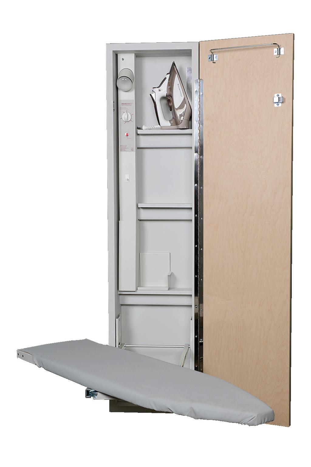
2 GET TO KNOW YOUR UNIT (BOTTOM OF RACEWAY) CROSS BRACES 2. ELECTRICAL RACEWAY 3. SIDE BRACKETS 4. ELECTRICAL CORD COVER 5. ELECTRICAL OUTLET 6. HOT IRON REST - Stud Finder Level - Tape Measure - Small Flathead Screwdriver Tools Needed: - Electric Drill (with 1/4 & 1/8 drill bit) - 1/4 Nut Driver (optional) - Safety Glasses - Utility Knife Supplied Parts: Recessed Mounting: - Two #10 x 1 1/2 wood screws for top portion of cabinet - Two #14 x 2 1/2 Phillips screws for top side brackets Surface Mounting: - Two #14 x 4 wood screws

3 PRE-INSTALLATION 1. DETERMINE MOUNTING HEIGHT Using the charts provided, determine the mounting height above floor (the distance between the floor and the bottom of the cabinet). First choose your desired ironing board height from the left column, then locate the corresponding mounting height in the right column. Desired Ironing Board Height Mounting Height Above Floor LOCATE STUDS & UTILITIES Using a stud finder, locate the wall studs to be used for mounting. Locate the existing wiring or other utilities in the wall to prevent drilling into/severing a wire and/or other utility during installation. Desired Ironing Board Height Mounting Height Above Floor

4 3. ENSURE ADEQUATE SPACE Refer to the chart provided below to ensure adequate clearance for ironing. The cabinet door opens at 180 degrees; allow 16 from side of cabinet for door to fully open. AE46 1. Distance needed on either side of unit to fully swivel the board 16 7/8 2. Distance from wall to tip of ironing board 50 7/8 3. Distance from wall to board when in full swivel position 32 7/8 4. Standing area clearance (not shown) The suggested distance from the side of the ironing where the user typically stands to ensure adequate space for ironing. 24


5 RECESSED INSTALLATION Note: Instructions based on installation between 16 on-center studs. 1. CUT WALL OPENING Cut an opening into the wall based on unit dimensions given below. 14 3/8 x 59 7/8 x 3 7/8 2. ATTACH CLEATS Attach a 2 x 4 cross support cleat between the studs so it is level with the bottom of the opening. This will give support to the drywall during installation and the cabinet once installed in the wall. 3. PRE-DRILL HOLES Your unit will be attached to the studs by screws in the upper and lower sides of the cabinet. Remove electrical raceway before proceeding by removing the top and bottom screws on the raceway. Using a 1/8 drill bit, pre-drill holes into the sides of the cabinet, 14 from the top and 2 1/2 from the back. 14 from top of cabinet 2 1/2 from back of cabinet Example shown with exposed studs & unit to illustrate mounting. CLEAT
6 Ensure that power is disconnected at service entrance before proceeding. 7. ATTACH CABINET TO STUDS Using the pre-drilled holes in top of cabinet, attach unit to studs with two #10 x 1 1/2 screws for top installation. 4. REMOVE ELECTRICAL KNOCKOUT Open the front cover of the raceway by removing the screw at the top and bottom of the raceway. Locate the electrical knockout, as specified on diagram provided. Install a 3/8 romex connector where the knockout was removed. 2 1/2 2 1/4 1 1/4 DIA. VENT HOLE FOR WIREWAY DOOR 5. INSTALL ELECTRICAL WIRING Verify that there is ample supply wire available to run from the top of the ironing center to the approximate location of electrical pigtails. Note: A free wire length of 48 is recommended. Begin to place the ironing center into its location while feeding the supply wire through electrical knockout, and the 3/8 romex connector through the back of the raceway. 6. INSTALL UNIT IN WALL Begin installation by carefully lifting unit into the wall opening. Make sure the cabinet is plumb and level. If needed, add shims to help unit fit snug in place. CABINET EXTERIOR Example shown with studs to illustrate mounting. 8. REMOVE BRACKET SCREW Locate side ironing board brackets that are secured to cabinet with three screws. Then remove the top screw from each bracket. This is where the bottom part of your cabinet will be secured to the studs.
7 9. PRE-DRILL HOLES IN SIDES Pre-drill holes into the cabinet using the holes in side brackets where screws were just removed. Finish installation by screwing the two #14 x 2 1/2 screws into the pre-drilled holes to secure bottom part of cabinet into the cabinet. 10. CONNECT WIRES Connect all power supply wires and ground wires in accordance with electrical codes. Trim supply wire as necessary. 11. REPLACE ELECTRICAL RACEWAY Place the raceway cover into position, ensuring that no wires are pinched. Reinstall the top and bottom screw to secure in place. Reconnect power supply. 12. INSTALLATION COMPLETE! Cabinet is now fully installed! If desired, decorative trim or molding may be added to cover any irregularities in the wall.
8 SURFACE MOUNT INSTALLATION 1. PREPARE CABINET Screws will be drilled through the upper and lower cross braces inside the cabinet. Determine location of screws, ensuring that the location of the mounting screw is as close to the center of the cabinet as possible. 2. PRE-DRILL PILOT HOLES Using a 1/4 drill bit, pre-drill holes in the upper and lower cross braces inside the cabinet as determined in previous step. Ensure that the holes in both braces are drilled to the same measurement. 3. LOCATE & MARK STUD Using a stud finder, locate stud in wall and mark the wall according to the pre-drilled holes in cabinet. Setting cabinet aside, pre-drill holes in wall using a 1/4 drill bit. Do not attempt to mount only through hard board of cabinet. 4. PARTIALLY INSERT SCREW Partially insert a #14 x 4 screw in the upper cross brace. 5. REMOVE ELECTRICAL KNOCKOUT Open the front cover of the raceway by removing the screw at the top and bottom of the raceway. Locate the electrical knockout, as specified on diagram provided. Install a 3/8 romex connector where the knockout was removed. Position of Electrical Knockout for SURFACE MOUNT ONLY 24 1/2 2 13/16 Example shown with studs & unit to illustrate mounting.
9 6. INSTALL ELECTRICAL WIRING Verify that there is ample supply wire available to run from the top of the ironing center to the approximate location of electrical pigtails. Note: A free wire length of 48 is recommended. Begin to place the ironing center into its location while feeding the supply wire through electrical knockout, and the 3/8 romex connector through the back of the raceway. 11. ADD TRIM Add Decorative trim or molding to make cabinet sides flush with the face frame. 12. REMOVE BRACKET SCREW Locate side ironing board brackets that are secured to cabinet with three screws. Then remove the top screw from each bracket. Replace with a #14 x 3/4 Phillips screw. This will add stability long-term. 7. INSTALL UNIT Begin installation by carefully lifting unit into position. Then, attach the cabinet to the wall by fully inserting the screw in the upper cross brace into the wall stud. Make sure the unit is plumb and level. Shim if necessary. Fully tighten installation screw. 8. INSERT SECOND SCREW Insert the second #14 x 4 screw into the pre-drilled hole in the bottom brace of the cabinet and attach to wall making sure cabinet remains square and level. 13. INSTALLATION COMPLETE Cabinet is now fully installed! 9. CONNECT WIRES Connect all power supply wires and ground wires in accordance with electrical codes. Trim supply wire as necessary. 10. REPLACE ELECTRICAL RACEWAY Place the raceway cover into position, ensuring that no wires are pinched. Reinstall the top and bottom screw to secure in place.
Installation Manual MODEL E-42
 Installation Manual MODEL E-42 GET TO KNOW YOUR UNIT 2 (BOTTOM OF RACEWAY) 1 3 1. CROSS BRACES 2. ELECTRICAL RACEWAY 3. ELECTRICAL OUTLET - Stud Finder - 12-14 Level - Tape Measure - Small Flathead Screwdriver
MODELS: AE46, AE42, E46, E42, ANE46, ANE42, NE46, NE42
 Installation Manual MODELS: AE46, AE42, E46, E42, ANE46, ANE42, NE46, NE42 TABLE OF CONTENTS SWIVEL UNITS (AE46, AE42, ANE46, ANE42)...pg.3 NON-SWIVEL UNITS (E46, E42, NE46, NE42)...pg.11 ELECTRICAL INSTRUCTIONS...pg.17
Installation Manual MODEL ANE-42
 Installation Manual MODEL ANE-42 GET TO KNOW YOUR UNIT 1 2 1. CROSS BRACES 2. SIDE BRACKETS - Stud Finder - 12-14 Level - Tape Measure - Small Flathead Screwdriver Tools Needed: - Electric Drill (with
Installation Manual MODEL NE-42
 Installation Manual MODEL NE-42 GET TO KNOW YOUR UNIT 1 1. CROSS BRACES - Stud Finder - 12-14 Level - Tape Measure - Small Flathead Screwdriver Tools Needed: - Electric Drill (with 1/4 & 1/8 drill bit)
Installation Manual Installation Manual
 Installation Manual Installation Manual TABLE OF CONTENTS Unpackaging Your Unit...Pg.3 Pre-Installation...Pg.5 Recessed Installation Instructions...Pg.7 Surface Mount Installation Instructions...Pg.10
INS T A L L A TIO N INS T R U C TIO N S. Ceiling Mount Track System
 Ceiling Mount Track System 10.26.2016 Specifications Ceiling Post: Unassembled 2-7/8 Assembled 1-11/16 7/8 7-9/16 5-7/8 3/8 2 Tubes 1/2 2-3/8 5 Parts and Tools Tools Needed Tape Measure Pencil Drill with
FRAMED CABINETRY INSTALLATION MANUAL
 FRAMED CABINETRY INSTALLATION MANUAL AN INDUSTRY GUIDE FOR PROFESSIONAL INSTALLATION RESULTS TO AVOID DAMAGE OR INJURY, READ IN ENTIRETY BEFORE STARTING MATERIAL & TOOL LIST FOR INSTALLATION Safety Glasses
Color Stories Studio Installation Instructions
 Tools Required 1 - Stud Finder 8 - Carpet Sliders 1 - Level 1 - Phillips Screwdriver 1 - Flathead Screwdriver 1 - Power Drill with 3/16 Bit 1 - Package of Shims 2-8 Ft. Step Ladder Components V (2) Wall
Inigo Sconce INSTALLATION INSTRUCTIONS P _2_A 1 of 5
 P31321 1 of 5 Thank You For Choosing Kallista We appreciate your commitment to Kallista quality products. Please take a moment to review this manual before you install your Kallista product. If you encounter
Box Track INSTALLATION INSTRUCTIONS
 Box Track INSTALLATION INSTRUCTIONS BOX TRACK Recommended Tools Level Tape Measure Pencil Drill with 1/8, and 1/4, Drill Bits, Phillips Bit and Slotted Bit Socket Wrench with 9/16 Socket 9/16 and 5/8 Wrench
Heavy Duty I-Beam Trolley
 Heavy Duty I-Beam Trolley ASSEMBLY INSTRUCTIONS I-BEAM TROLLEY Recommended Tools Level Tape Measure Pencil Drill with 1/8, 1/4, and 3/8, Drill Bits and Phillips Bit Socket Wrench with 9/16 Socket I-BEAM
INSTALLATION MANUAL. All Recessed Wall-Mount Modules Front-Loading, Rear-Loading, Parcel-Only, Collection Box, Trash/Recycling Bin
 INSTALLATION MANUAL All Recessed Wall-Mount Modules Front-Loading, Rear-Loading, Parcel-Only, Collection Box, Trash/Recycling Bin TABLE OF CONTENTS GENERAL INFORMATION AND ADVISORIES 3 USPS INSTALLATION
M10 x 75mm Sockethead Cap Screws. 5mm Fender Washer (12) Included - (8) Required. #10 x 2.5" PH Wood Screws. (30) Included - (24) Required
 Included - (8) Required. #10 x 2.5 PH Wood Screws. (30) Included - (24) Required") Door System Unit - Hardware Tools Included: (2) 2mm Allen Wrenches, (2) 3mm Allen Wrenches, (2) 4mm Allen Wrenches, (2) 6mm Allen Wrenches, and (1) 8mm T-Handle Allen Wrench Tools Required: Phillips Screwdriver,
Door System Unit - Hardware Tools Included: (2) 2mm Allen Wrenches, (2) 3mm Allen Wrenches, (2) 4mm Allen Wrenches, (2) 6mm Allen Wrenches, and (1) 8mm T-Handle Allen Wrench Tools Required: Phillips Screwdriver,
Yes 20 Charging Wall Cabinet for Tablets
 Built with Anthro-DNA Owner's Manual for Yes 20 Charging Wall Cabinet for Tablets Part # YESCABGMPW Components at a Glance 1 2 4 5 8 7 10 3 6 9 Front of Cabinet (closed) 1. Locking front door to User area.
Pet Door Panel Installation Manual
 Pet Door Panel Installation Manual 400-558-1 1 4/3/03, 3:26 PM Components: Pet Door Panel Panel Latch Assembly Foam Weather-stripping Glass Sweep (4) Binding Posts (6) #6 x 1/2 Sheet Metal Screws (4) 8-32
Closet System Installation Manual
 Closet System Manual Thank you For choosing our Custom Closet Collection to fit all your needs Closets come fully assembled to make your project an enjoyable and satisfying experience. With quality Custom
Mod e l A urora P l u s Walk-In Doo r
 Installation Instructions Mod e l A urora P l u s Walk-In Doo r Contractors Wardrobe DESIGNERS MANUFACTURERS TOLL FREE: (800) CW-DOORS (800) 29-66 www.cwdoor.com 26121 Avenue Hall Valencia, CA 9155 (661)
GE Monogram. Installation. Instructions. 36" Vent Hood. Model ZV750. Call anywhere in the US and Canada -
 at :: rangehoods. com GE Monogram Instructions Model ZV750 GE Monogram at:: rangehoods. com is a division of CAUTION WARNING Before you begin Read these instructions completely and carefully. IMPORTANT:
Signal Mirror Installation Instructions
 Signal Mirror Installation Instructions 2006 2007 Honda Ridgeline THE safety accessory of the 21 st Century. P/N 210 0142 0 Rev. A (9/5/07), BTV 2007 Muth Company, LLC Professional Installation Recommended:
Installation Instructions For TruLine 1.6A 24VDC
 2014 Pure Lighting. All Rights Reserved. Installation Instructions For TruLine 1.6A 24VDC INS# 902-TL1.6A-07 1718 W. Fullerton Ave Chicago, IL 60614 Tel: 773-770-1195 Fax: 773-935-5613 www.purelighting.com
Yes 20 Charging Wall Cabinet for Tablets
 Built with Anthro-DNA Owner's Manual for Yes 20 Charging Wall Cabinet for Tablets Part # YESCABGMPW Components at a Glance 1 2 4 5 8 7 10 Front of Cabinet (closed) 1. Locking front door to User area. 2.
x2 1/4 (6mm) Floor Anchor
 Floor Anchor") INSTALLATION GUIDE Main Components x1 Rail x5 Wall Spacer x2 Anti-jump Block x2 Straight Strap x1 Right Stopper x1 Left Stopper x5 5/16 (8mm x 60mm) Carriage Bolt x5 5/16 (8mm x25mm) Anchor x5 5/16 (8mm
INSTALLATION GUIDE Main Components x1 Rail x5 Wall Spacer x2 Anti-jump Block x2 Straight Strap x1 Right Stopper x1 Left Stopper x5 5/16 (8mm x 60mm) Carriage Bolt x5 5/16 (8mm x25mm) Anchor x5 5/16 (8mm
Top Mount Ultra Modern Hanger
 Top Mount Ultra Modern Hanger ASSEMBLY INSTRUCTIONS TOP MOUNT ULTRA MODERN HANGER Recommended Tools Level Tape Measure Pencil Drill with 1/8, and 1/4, Drill Bits and Phillips Bit Socket Wrench with 9/16
Signal Mirror Installation Instructions Honda Odyssey
 Signal Mirror Installation Instructions 2005-2009 Honda Odyssey THE safety accessory of the 21st Century. P/N 210-0122-0 Rev. A4 (6/9/09), BTV 2006 Muth Company, LLC PROFESSIONAL INSTALLATION RECOMMENDED
Cabinetry Installation
 Cabinetry Installation Easy to follow step-by-step kitchen cabinet installation Hammer Pry bar Screwdriver Phillips Flathead Level TOOL AND MATERIAL LIST Tape measure Pencil Straight edge Drill 3/16" drill
GE Monogram. Installation. Instructions. 27" Built-In Ovens. Models ZEK757WW ZEK757BW ZEK737WW ZEK737BW
 GE Monogram Installation Instructions 27" Models ZEK757WW ZEK757BW ZEK737WW ZEK737BW CAUTION WARNING Before you begin Read these instructions completely and carefully. IMPORTANT: Save these instructions
Panel & Shelf Identification
 4 to 8 Aromatic Cedar Closet Model # 801 1 PLEASE READ INSTALLATION INSTRUCTIONS BEFORE ASSEMBLING Rev. C IF YOU ARE MISSING PARTS OR HAVE QUESTIONS PLEASE CONTACT: customerservice@cedargreen.net Tools
Contour Hanger ASSEMBLY INSTRUCTIONS
 Contour Hanger ASSEMBLY INSTRUCTIONS CONTOUR HANGER Recommended Tools Drill with 1/8, 1/4, and 3/8 Drill Bits, 1-1/8 Forstner Bit or 1-1/8 Spade Bit, and Phillips Bit 9/16 and 5/8 Combination Wrench Socket
Industrial Hanger ASSEMBLY INSTRUCTIONS
 Industrial Hanger ASSEMBLY INSTRUCTIONS INDUSTRIAL HANGER Recommended Tools Drill with 1/8, 1/4, and 3/8 Drill Bits, 1-1/8 Forstner Bit or 1-1/8 Spade Bit, and Phillips Bit 9/16 and 5/8 Combination Wrench
Household Appliances. Over-the-Range Microwave. Installation Instructions. For Models: HMV9302, HMV9305, HMV9306, HMV9307
 Over-the-Range Microwave Household Appliances Installation Instructions For Models: HMV9302, HMV9305, HMV9306, HMV9307 PLEASE READ ENTIRE INSTRUCTIONS BEFORE PROCEEDING IMPORTANT: Save these instructions
SAFETY THIS PRODUCT IS FOR OFFROAD USE ONLY. ALL LIABILITY FOR INSTALLATION AND USE RESTS WITH THE OWNER.
 SAFETY Your safety and the safety of others is very important. In order to help you make informed decisions about safety, we have provided installation instructions and other information. These instructions
MISCELLANEOUS CABINET REPAIRS
 MISCELLANEOUS CABINET REPAIRS 167 168 NOTES MISCELLANEOUS CABINET REPAIRS Cabinet Panel Repairs 175 SIDE PANEL REPLACEMENT - GDM SERIES INSTALLATION INSTRUCTIONS Tools Required 1/8" drill Rivet Tool Silicone
G. H. I. N. J. O. 22"x 28" Poster Holder. P. Q. romotional wall displ
 Wall Display Assembly Instructions Tools necessary for assembly 1. Electric drill with Phillips head 2. Adjustable wrench or pliers 3. One or two step ladders or stools Due to the weight of the side panels
GE Monogram. Installation. Instructions. Microwave Oven. Under Cabinet Installation. and. JX827 Series Built-In Kit. Models.
 GE Monogram Installation Instructions Under Cabinet Installation and JX827 Series Built-In Kit Models ZEM200 Series CAUTION WARNING Before you begin Read these instructions completely and carefully. IMPORTANT:
Installation Instructions
 Installation Instructions READ BEFORE INSTALLING UNIT For Slider Casement Air Conditioners INSTALLATION WARNINGS AND CAUTION Carefully read the installation manual before beginning. Follow each step as
Installation Instructions
 by Plato Woodwork Installation Instructions Plato Woodwork, Inc. 200 Third Street SW P.O. Box 98 Plato, MN 55370 www.platowoodwork.com 800.328.5924 SECTION GUIDE GETTING STARTED PAGE # Installation Methods...
TWIG Hanger ASSEMBLY INSTRUCTIONS
 TWIG Hanger ASSEMBLY INSTRUCTIONS TWIG HANGER Recommended Tools Drill with 1/8, 1/4, and 3/8 Drill Bits, 1-1/8 Forstner Bit or 1-1/8 Spade Bit, and Phillips Bit 9/16 and 5/8 Combination Wrench Socket Wrench
Installation Instructions
 For Medium (15-18.5K) + Heavy duty (-8.5K) Air Conditioner READ BEFORE INSTALLING UNIT To avoid risk of personal injury, property damage, or product damage due to the weight of this device and sharp edges
Cellar Hanger ASSEMBLY INSTRUCTIONS
 Cellar Hanger ASSEMBLY INSTRUCTIONS CELLAR HANGER Recommended Tools Drill with 1/8 and 1/4 Drill Bits, 1-1/8 Forstner Bit or 1-1/8 Spade Bit, and Phillips Bit 9/16, 7/16, and 5/8 Combination Wrench Socket
EmagiKit. Privacy Pod Plus. Quiet. Easy. Affordable. INSTRUCTIONS ASSEMBLY
 EmagiKit Privacy Pod Plus Quiet. Easy. Affordable. INSTRUCTIONS ASSEMBLY DIMENSIONS AND COMPONENTS 47 47 Ceiling Unit 2-B 2-L 2-R Glass Door Corner Trim Door Handle 90 Adjustable Height Work Surface 1-B
Motorized or Crank Operated Fortress Zipper Track Shade with Housing and Side Track Installation Instructions
 Motorized or Crank Operated Fortress Zipper Track Shade with Housing and Side Track Installation Instructions Tools Needed Drill 3/8 Metal Drill Bit ¼ Masonry Drill Bit Measuring Tape Pencil 4 Level Phillips
C-Series & S-Series Classic Frame with Transom (Single or Pair)
") 1. TOOLS REQUIRED Tape measure 6' magnetic level 3' magnetic level Safety Glasses Screw gun #2 Screwdriver tip #3 Screwdriver tip Philips Head screwdriver (Used to move frame on wall using oval slots on
1. TOOLS REQUIRED Tape measure 6' magnetic level 3' magnetic level Safety Glasses Screw gun #2 Screwdriver tip #3 Screwdriver tip Philips Head screwdriver (Used to move frame on wall using oval slots on
Installation Instruction
 Tools Needed for Assembly Stud finder (for wood stud wall) Pencil Mark Electric drill Wood Stud Wall Installation Step 1. Locate the Wood Studs Installation Instruction Drill bit (for wood stud wall) Masonry
x2 1/4 (6mm) Floor Anchor
 Floor Anchor") Main Components x1 Rail x5 Wall Spacer x2 Anti-jump Block x2 Bent Strap x1 Right Stopper x1 Left Stopper x5 5/16 (8mm x 60mm) Carriage Bolt x5 5/16 (8mm x25mm) Anchor x5 5/16 (8mm x 90mm) Wall Screw x2
Main Components x1 Rail x5 Wall Spacer x2 Anti-jump Block x2 Bent Strap x1 Right Stopper x1 Left Stopper x5 5/16 (8mm x 60mm) Carriage Bolt x5 5/16 (8mm x25mm) Anchor x5 5/16 (8mm x 90mm) Wall Screw x2
INSTALLATION GUIDE MICROWAVE OVEN UPMC3084ST. MFL _00
 INSTALLATION GUIDE MICROWAVE OVEN UPMC3084ST MFL06208710_00 www.thesignaturekitchen.com YOUR SAFETY FIRST BEFORE YOU START Proper installation is the installer's responsibility! Proper installation by
Vir Stil Console Lavatory INSTALLATION INSTRUCTIONS
 THANK YOU FOR CHOOSING KALLISTA We appreciate your commitment to Kallista quality products. Please take a moment to review this manual before you install your Kallista product. If you encounter any installation
Media Storage Systems Fixed Media Cabinets
 Owner s Manual Media Storage Systems Fixed Media Cabinets Contents 1-Column Fixed Media Storage Cabinet Important User Information...........................2 Safety Precautions.................................3
Closet Carousel Installation Instructions. Models TKA 5 Through TKA 14 Equipped with Footswitch Controls
 Tools Required: Phillips Screwdriver (#2) Adjustable Wrench Level Tape Measure Utility Knife Electric Drill Drill Bits for Anchors Ladder (4 foot) Models TKA 5 Through TKA 14 Equipped with Footswitch Controls
DX-TVMLPTB03. Low-Profile TV Wall Mount ASSEMBLY GUIDE. For either wood-stud or concrete wall installations
 ASSEMBLY GUIDE DX-TVMLPTB03 Low-Profile TV Wall Mount For either wood-stud or concrete wall installations Safety information and specifications...2 Tools needed...........................3 Package contents......................3
VERDERA T01-A INSTALLATION INSTRUCTIONS MIRRORED CABINET K-99003T-R/K-99003T-L K-99005T-R/K-99005T-L K-99009T
 VERDERA INSTALLATION INSTRUCTIONS MIRRORED CABINET K-99003T-R/K-99003T-L K-99005T-R/K-99005T-L K-99009T BEFORE YOU BEGIN Please read these instructions carefully to familiarize yourself with the required
INSTALLATION MANUAL DASH. friant.com/dash
 INSTALLATION MANUAL DASH friant.com/dash 2 DASH INSTALLATION MANUAL General Information... 4 Safety & Support... 5 Installation Tools... 6 Staging & Installation... 7 Tabletops Freestanding Tabletops...
Pillar Hanger ASSEMBLY INSTRUCTIONS
 Pillar Hanger ASSEMBLY INSTRUCTIONS PILLAR HANGER Recommended Tools Drill with 1/8, 1/4, and 3/8 Drill Bits, 1-1/8 Forstner Bit or 1-1/8 Spade Bit, and Phillips Bit 9/16 and 5/8 Combination Wrench Socket
4 Column Standard Corner
 4 Column Standard Corner Page 1 IMPORTANT! If you purchased a 2 Column Standard Corner Kit, your package will contain the following parts: END LADDER ASSEMBLIES - x4 1 COLUMN SCREWLESS CONNECTORS - x4
Barn Door & Hardware Installation Guide
 Barn Door & Hardware Guide INTRODUCTION Thank you for purchasing our hardware. Our barn door and hardware will add a stunning accent to your living environment and maximize its space. This manual covers
INSTALLATION INSTRUCTIONS
 INSTALLATION INSTRUCTIONS For Wallbed models: Do-It-Yourself BOOKLET #C90 WARNING! ALL MURPY/WALLBED SYSTEMS CONTAIN STORED ENERGY. FAILURE TO USE AND FOLLOW THESE INSTRUCTIONS DURING THE INSTALLATION
Sliding Door Hardware Installation Instructions ROB ROY
 Sliding Door Hardware Installation Instructions ROB ROY Installation Instructions Structural Information For standard systems and most custom single door opening systems. General Overview All Krown Lab
ASSEMBLY INSTRUCTION FOR WYTHE BURLED WOOD BAR
 ASSEMBLY INSTRUCTION FOR WYTHE BURLED WOOD BAR IMPORTANT SAFETY INSTRUCTIONS: Please read all instructions carefully before assembling. For your safety, assembly by two or more adults is strongly recommended.
Installation Instructions
 READ BEFORE INSTALLING UNIT For Slider Casement Air Conditioners To avoid risk of personal injury, property damage, or product damage due to the weight of this device and sharp edges that may be exposed:
MINI Cooper Model 120SA Installation Instructions
 MINI Cooper Model 120SA Installation Instructions Please read these instructions completely before beginning the installation. Test fit all components (amplifier, etc.) before mounting. These instructions
CALLAS THERMOSTATIC SHOWER SET
 SKU(s): 925945 CALLAS THERMOSTATIC SHOWER SET BEFORE YOU BEGIN We recommend consulting a professional if you are unfamiliar with installing plumbing fixtures. Signature Hardware accepts no liability for
SECURITY DOORS - 2', 3', 4'
 INTRODUCTION: CAREFULLY READ THE CONTENTS OF THESE INSTRUCTIONS, AS THEY INDICATE THE CORRECT STEP BY STEP PROCEDURE TO ASSEMBLE THE PRODUCT. THE CARTON CONTENTS PAGE(S) WILL IDENTIFY THE ASSEMBLY PARTS.
Installation Instructions
 TS SERIES Traditional Square Accessories Installation Instructions " TOWEL BAR.0 " TOWEL BAR.0.90 DOUBLE ROBE HOOK.0.0 " HANDLE. " HANDLE.0 Thank you for selecting American-Standard...the benchmark To
Installation Instructions for Converting Hinging on Roll-In Refrigerators
 Installation Instructions for Converting Hinging on Roll-In Refrigerators Part number 161651 hinge conversion kit RH is for converting a right side hinged door and part number 161652 hinge conversion kit
OVER THE RANGE MICROWAVE OVEN INSTALLATION INSTRUCTIONS
 OVER THE RANGE MICROWAVE OVEN INSTALLATION INSTRUCTIONS Please read and save these installation instructions. MODEL NO.: DOTR12CWIV/DOTR12CBIV P/N: 3828W5U0202 YOUR SAFETY FIRST Read this entire manual
Inde-Pendants Family. 32L Ring Plaster Trim, Grid and Drywall Ceiling Types. Document No Installation instructions for 32L-Rxx-P
 Inde-Pendants Family 32L Ring Plaster Trim, Grid and Drywall Ceiling Types Installation instructions for 32L-Rxx-P Document No. Supplied by Litecontrol 32L Inde-Pendants: Ring (Plaster Trim, Grid and Drywall
LCD LIFT Flat Panel Display System Installation Manual. Table of Contents
 LCD LIFT Flat Panel Display System Installation Manual Table of Contents Page Installation Overview... 2 Trim Ring Installation... 3 LCD Lift Installation....4 Actuator Switch Installation.5 Top Plate
Mirage Installation Manual
 Mirage Installation Manual General Information This installation manual provides necessary information for the safe installation of the Mirage product. WARNING: Failure to follow the instructions in this
Required Tools: Suggested Additional Tools: 1 Cordless Drill with Robertson Bits 1 Ratchet Wrench 1 7/16 or 11mm socket 1 7/16 or 11mm Gear Wrench
 Thank you for your recent purchase of a Cabinets by Hayley garage cabinet system. You are about to experience the best made cabinets that you can purchase. Cabinets by Hayley are designed for beauty and
Installation Instructions For Heavy Duty (FAS Models) and Median (FAM Models) Air Conditioners
 and Median (FAM Models) Air Conditioners") Installation Instructions For Heavy Duty (FAS Models) and Median (FAM Models) Air Conditioners Please read ALL instructions before installing. Two people are recommended to install this product. If a new
Installation Instructions For Heavy Duty (FAS Models) and Median (FAM Models) Air Conditioners Please read ALL instructions before installing. Two people are recommended to install this product. If a new
YES 12 Charging Wall Cabinet for Mini-laptops
 Built with Anthro-DNA Owner's Manual for YES 12 Charging Wall Cabinet for Mini-laptops Part # YESMLCGMPW Components at a Glance 7 1 9 8 2 4 5 11 6 10 3 Front of Cabinet (closed) 1. Locking front door to
Inde-Pendants Family. 32L Surface Mount Cylinder with Ring Plaster Trim, Grid and Drywall Ceiling Types. Document No
 Inde-Pendants Family 32L Surface Mount Cylinder with Ring Plaster Trim, Grid and Drywall Ceiling Types Installation instructions for 32L-CRxx-S-D Document No. Supplied by Litecontrol 32L Inde-Pendants:
MODULAR LED UNDERCABINET LIGHTING SYSTEM Max 540watts IMPORTANT SAFETY INSTRUCTIONS
 MODULAR LED UNDERCABINET LIGHTING SYSTEM Max 540watts IMPORTANT SAFETY INSTRUCTIONS INSTRUCTIONS PERTAINING TO A RISK OF FIRE, ELECTRIC SHOCK OR INJURY TO PERSONS GENERAL 1. To insure the success of the
INSTALLATION INSTRUCTIONS FOR FRONT CASTING DECK RAIL Ranger
 INSTALLATION INSTRUCTIONS FOR FRONT CASTING DECK RAIL Ranger TOOLS REQUIRED FOR INSTALLATION: Drill motor, (1) 5/16 inch drill bit, (1) 13/64 drill bit, (1) 3/16 inch hex wrench (1) 3/32 inch hex wrench.
WILDING WALLBEDS INSTALLATION INSTRUCTION Side Mount
 WILDING WALLBEDS INSTALLATION INSTRUCTION Side Mount For Wallbed models: Do-It-Yourself Insturction booklet C92 WARNING! ALL MURPHY/WALLBED SYSTEMS CONTAIN STORED ENERGY. FAILURE TO USE AND FOLLOW THESE
19 to 39 TV WALL MOUNT - FULL MOTION
 19 to 39 TV WALL MOUNT - FULL MOTION RF-HTVMMAB For wood-stud and concrete wall installations Safety information and specifications...2 Tools needed...2 Package contents...3 Installation instructions...5
Stag Hanger ASSEMBLY INSTRUCTIONS
 Stag Hanger ASSEMBLY INSTRUCTIONS STAG HANGER Recommended Tools Drill with 1/8, 1/4, and 3/8 Drill Bits, 1-1/8 Forstner Bit or 1-1/8 Spade Bit, and Phillips Bit 9/16 and 5/8 Combination Wrench Socket Wrench
Installation Instructions
 READ BEFORE INSTALLING UNIT INSTALLATION WARNINGS AND CAUTION Carefully read the installation manual before beginning. Follow each step as shown. Observe all local, state, and national electrical codes
Chapter 22 - Cabinets & Vanities
 Chapter 22 - Cabinets & Vanities Contents Chapter 22 - Cabinets & Vanities... 22-1 Timing & Prerequisites... 22-2 Cabinets... 22-3 Cabinet Layout... 22-3 Wall Cabinets... 22-4 Assemble the Wall Units...
Video Wall Installation Instructions 2W X 3H, 3W X 3H
 Video Wall Installation Instructions 2W X 3H, 3W X 3H www.microndisplaysolutions.com Table of Contents Important Safety Instructions... 3 Configuration... 4 Package Contents, included and optional items...
compile system INSTALLATION GUIDE Updated January 2019
 INSTALLATION GUIDE Updated January 09 compile system Table of Contents Panels 0 Quick Connect Clips 0 Lock Clips 0 Panel Trims 0 Privacy Glass 0 Post Base Covers 04 Electrical 04 Power Distribution Harness
Installation. Instructions. Built-In Microwave/Convection and Microwave Ovens. Models ZMC1095 JEB1095 JEB1055
 Installation Instructions Built-In Microwave/Convection and Microwave Ovens Models ZMC1095 JEB1095 JEB1055 Before you begin Read these instructions completely and carefully. IMPORTANT: Save these instructions
Triple Bypass System
 Triple Bypass System ASSEMBLY INSTRUCTIONS TRIPLE BYPASS SYSTEM Recommended Tools Drill with 1/4 Drill Bit and Phillips Screw Bit 7/16 Combination Wrench Socket Wrench with 7/16 and 9/16 Socket Level Tape
Full Height Diamond bin. Package Contents
 Page 1 Package Contents *Please verify that you have the correct number of parts before proceeding. Depending on the model you purchased, your bundle should contain the following: tools for assembly Required
Joiner Kit Joiner bracket (x1) Biscuit aligners (x2) Trim Flange
 Biscuit aligners (x2) Trim Flange") - Trim System Overview These instructions review how to install TruGroove Perimeter fixtures. Modules can be installed as individual standalone units, or they can be joined together to create continuous
- Trim System Overview These instructions review how to install TruGroove Perimeter fixtures. Modules can be installed as individual standalone units, or they can be joined together to create continuous
BUILDERS ONE Framed Cabinet. Installation Manual
 BUILDERS ONE Framed Cabinet Installation Manual 1 BEFORE YOU BEGIN: Check your cabinetry against your design plan to ensure that you have all required cabinetry moldings, fillers and accessories to complete
Replacement Guide. For Handle Side Z-bar on Fullview Doors with Laminated Glass and Multi-Point Locking System RECOMMENDED TOOLS:
 Replacement Guide For Handle Side Z-bar on Fullview Doors with Laminated Glass and Multi-Point Locking System IMPORTANT: READ ENTIRE GUIDE BEFORE BEGINNING INSTALLATION. PLEASE NOTE: Proper assembly, installation
Installation Instructions
 For Medium (15-18.5K) + Heavy duty (22-28.5K) Air Conditioner READ BEFORE INSTALLING UNIT To avoid risk of personal injury, property damage, or product damage due to the weight of this device and sharp
Basic Spring Motor Roller Shades
 Basic Spring Motor Roller Shades ATTENTION!!! READ CAREFULLY! This shade has a reliable long-lasting Spring Motor. The Spring Motor must have proper tension in order to function as intended. Handling in
Safety First! Review the Safety Checklist before performing tasks in this chapter.
 Chapter 17. Cabinets 17.1 LAYING OUT KITCHEN CABINET UPPER UNITS 17.2 INSTALLING KITCHEN CABINET SUPPORT STRIPS 17.3 INSTALLING KITCHEN CABINET UPPER UNITS 17.4 INSTALLING RANGE HOOD 17.5 INSTALLING KITCHEN
BARN DOOR HARDWARE KIT
 INSTALLATION GUIDE Main Components x1 Rail x5 Wall Spacer x2 Anti-jump Block x2 Bent Strap x1 Right Stopper x1 Left Stopper x5 5/16 (8mm x 60mm) Carriage Bolt x5 5/16 (8mm x25mm) Anchor x5 5/16 (8mm x
INSTALLATION INSTRUCTIONS
 INSTALLATION INSTRUCTIONS SOLID PHENOLIC TOILET PARTITIONS 1080 DuraLine Series 1180 DuraLine Series Class-A Fire Rated IMPORTANT: Review these instructions thoroughly prior to installation. FLOOR ANCHORED
Whalen Furniture Mfg. Factory No. 5 Page # 1
 If you have any questions regarding assembly or if you are missing parts, do not return this item to Sam s Wholesale Club Please call our customer service number and have your instructions and parts list
" BASE CABINET
 INSTALLATION GUIDE INSTALLATION GUIDE Before You Begin Installing Your Kitchen Cabinets 1. Read through installation guide to understand all steps and gather tools needed. 2. Verify that all of the hardware,
Installation Instructions For Slider Casement Air Conditioners
 Installation Instructions For Slider Casement Air Conditioners NOTE: These instructions describe installation in a typical wood framed window with a wood SLIDE-BY sash, or installation in a metal CASEMENT
ZHONGSHAN KOHLER SHOWER CO., LTD. NO13-1, XINGYE ROAD, ZHONGSHAN TORCH DEVELOPMENT ZONE, ZHONGSHAN, GUANGDONG, CHINA POST CODE:
 NEW VERDERA INSTALLATION INSTRUCTIONS MIRRORED CABINET K-78202T-L/K-78202T-R/K-78282T BEFORE YOU BEGIN Please read these instructions carefully to familiarize yourself with the required tools, materials,
Ripple Hanger ASSEMBLY INSTRUCTIONS
 Ripple Hanger ASSEMBLY INSTRUCTIONS RIPPLE HANGER Recommended Tools Drill with 1/8, 1/4, and 1/2 Drill Bits, 1-1/8 Forstner Bit or 1-1/8 Spade Bit, and Phillips Bit 9/16 and 5/8 Combination Wrench Socket
Installation Instructions
 Installation Instructions Self-Cleaning Radiant Trivection Electric Slide-In Range JS998 Questions? Call 800.GE.CARES (800.432.2737) or Visit our Website at: www.geappliances.com BEFORE YOU BEGIN Read
INSTALLATION INSTRUCTIONS INS T A L L A TIO N INS T R U C TIO N S ROD IRON SCROLL HANGER R H
 INS T A L L A TIO N INS T R U C TIO N S ROD IRON SCROLL HANGER 10.5.2016 2-1- 3/16" 11/16" 8" 8 O 2-7/8 Ø2-7/8" 3-1/2 3-1/2" 12-9/16 12-9/16" PLEASE NOTE: These instructions are specific to a particular
SINGLE TRACK BYPASS (patent pending) barn door hardware
 barn door hardware") SINGLE TRACK BYPASS (patent pending) barn door hardware Installation Manual What is included in your kit: Part number Part name Quantity 1 Inner door hanger 2 2 Outer door hanger 2 3 5/16 x 1.5 lag bolts
SINGLE TRACK BYPASS (patent pending) barn door hardware Installation Manual What is included in your kit: Part number Part name Quantity 1 Inner door hanger 2 2 Outer door hanger 2 3 5/16 x 1.5 lag bolts
Installation Instructions for TruLine 1.6A 24VDC. Section One: Basic Configuration Options
 Doc # 902-TL1.6A_07 1718 W. Fullerton Chicago, IL 60614 Ph: 773.770.1195 Fax: 773.935.5613 www.pureedgelighting.com info@pureedgelighting.com 2016 PureEdge Lighting. All Rights Reserved. Installation Instructions