SEAT-SUPPORTED COAT HANGER FOR AUTOMOBILES [HANGING GARMENTS ON SEATS]
|
|
|
- Loren Henderson
- 6 years ago
- Views:
Transcription
1 SEAT-SUPPORTED COAT HANGER FOR AUTOMOBILES [HANGING GARMENTS ON SEATS] CROSS-REFERENCE TO RELATED APPLICATIONS [0001] Not applicable. 5 PRIORITY CLAIM [0002] Option 1: This application claims benefit of Provisional Appln. 60/NNN,YYY, filed MMMM XX, YYYY, the entire contents of which is hereby incorporated by reference as if fully set forth herein, under 35 U.S.C. 119(e).] [Option 2: This application claims benefit as a [select: Continuation / Continuation-in-part ] of Appln. Ser. No. 09/XXX,YYY, filed MMMM XX, YYYY the entire contents of which is hereby incorporated by reference as if fully set forth herein, under 35 U.S.C. 1. The applicant(s) hereby rescind any disclaimer of claim scope in the parent application(s) or the prosecution history thereof and advise the USPTO that the claims in this application may be broader than any claim in the parent application(s).] FEDERALLY SPONSORED RESEARCH OR DEVELOPMENT [0003] Not applicable. PARTIES TO JOINT RESEARCH AGREEMENT [0004] Not applicable. SEQUENCE LISTING [0005] Not applicable. BACKGROUND OF THE INVENTION [BACKGROUND?] 1. Field of the Invention [Disclosure?] [0006] This invention relates to garment hangers for use in automobiles, and particularly to a coat hanger adapted for detachable attachment on the back support portion of a cushioned automobile seat. -1-
2 Description of the Prior Art [0007] The approaches described in this section could be pursued, but are not necessarily approaches that have been previously conceived or pursued. Therefore, unless otherwise indicated herein, the approaches described in this section are not prior art to the claims in this application and are not admitted to be prior art by inclusion in this section. [The reference to any prior art in this specification is not, and should not be taken as an acknowledgment or any form of suggestion that the referenced prior art forms part of the common general knowledge.] [0008] A preliminary patentability and novelty search conducted in connection with my invention revealed the existence of four U.S. patents as follows: 2,557,537; 2,605,906; 3,007,617; 3,9,211. Referring to the patents noted above, U.S. Pat. Nos. 2,557,537 and 2,605,906 relate to garment hangers for use in an automobile, but the structures illustrated and described are completely different, being designed to engage the top edge of a car window. [0009] U.S. Pat. No. 3,007,617 also relates to a coat hanger for use in an automobile, but is designed to be mounted on an unoccupied seat, and by its design, prevents normal use of the seat on which it is mounted. [00] U.S. Pat. No. 3,9,211 relates to a lunch box holder mounted on a car seat. This device also prevents normal use of the seat on which it is mounted. [0011] There are few activities more destructive to fine suit coats and jackets than wearing such coats and jackets while sitting in an automobile, whether as the driver or a passenger. Because of the cramped quarters of modern-day cars, and the need to shift the body from time to time, severe stresses are imposed on seams, particularly in the shoulder area and on lining material. Accordingly, one of the objects of the present invention is the provision of a coat hanger that may easily be mounted on the back support portion of a cushioned seat structure to provide a convenient support on which a doffed suit coat or jacket may be hung. [0012] Apart from destructive stresses imposed on seams, wearing a suit coat or jacket while seated in an automobile almost always results in the formation of unsightly wrinkles in the material. It is therefore another object of the invention to provide a coat -2-
3 5 hanger that enables suspension of a coat or jacket at full length behind the driver's seat or behind the front passenger seat so as to preclude the formation of such wrinkles. [0013] Thus, the technical problem addressed in this disclosure is how to support a coat within the cabin of an automobile without causing wrinkles, imposing destructive stresses, or occupying excessive space within the cabin. [0014] The invention possesses other objects and features of advantage, some of which, with the foregoing, will be apparent from the following description and the drawings. It is to be understood however, that the invention is not limited to the embodiment illustrated and described, since it may be embodied in various forms within the scope of the appended claims. 30 SUMMARY OF THE INVENTION [00] In terms of broad inclusion, the coat hanger of the invention comprises a main body portion including a central coat collar supporting section and oppositely extending support sections projecting from the central section for supporting the shoulder portions of a suit coat or jacket. The main body portion may be formed from wood or plastic to provide an underside to which are attached a pair of spaced support straps, preferably formed from spring steel, and provided with lower end portions formed into resilient inverted U-shaped clamps adapted to resiliently grasp the upper end, front and back surfaces of the back support portion of a seat to which it is applied. The main body portion of the coat hanger thus projects above the upper end of the back support portion to provide a convenient support on which a coat or jacket may be hung. [0016] In an embodiment, the disclosure provides a coat hanger for use in an automobile having a cushioned seat including a back support portion having front, back and upper end surfaces for suspending a doffed coat in a wrinkle-free manner thereon, comprising (a) a main body portion having upper and lower surfaces and including a central coat collar supporting section and oppositely extending coat shoulder support sections; and (b) means mounted on the lower surface of said main body portion adapted to detachably engage the back support comprising a pair of spaced straps each attached at one end to the main body portion and terminating at its opposite end in an inverted U- shaped clamping portion adapted to engage the cushioned back support portion of the -3-
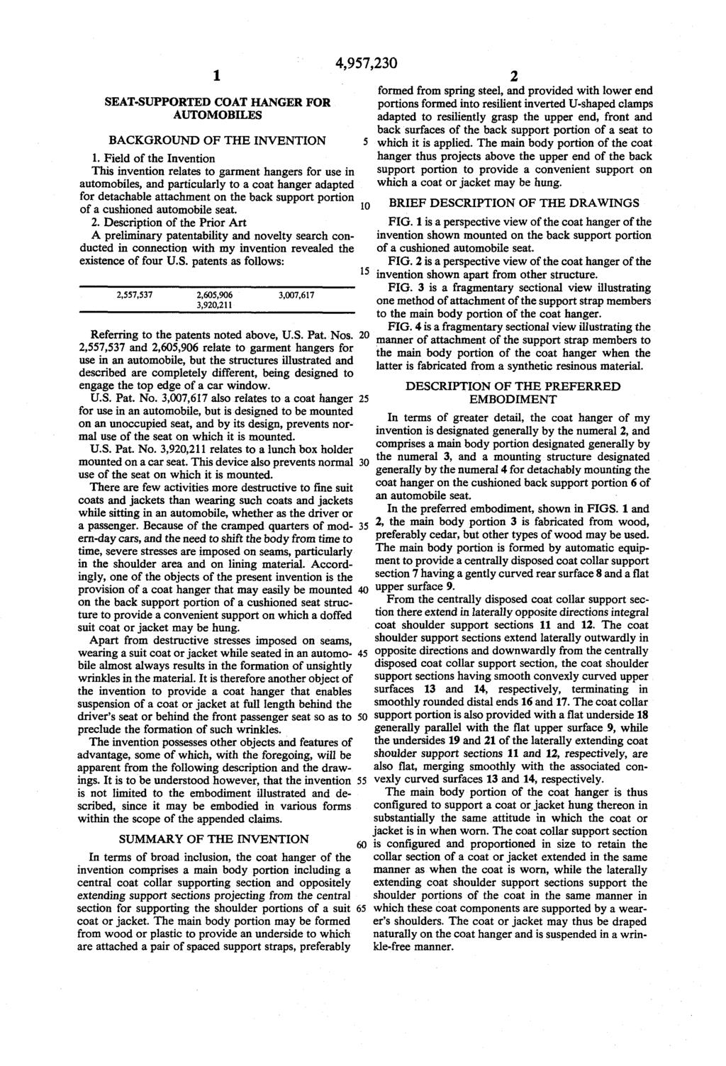
4 automobile seat BRIEF DESCRIPTION OF THE DRAWINGS [0017] In the drawings: [0018] FIG. 1 is a perspective view of the coat hanger of the invention shown mounted on the back support portion of a cushioned automobile seat. [0019] FIG. 2 is a perspective view of the coat hanger of the invention shown apart from other structure. [00] FIG. 3 is a fragmentary sectional view illustrating one method of attachment of the support strap members to the main body portion of the coat hanger. [0021] FIG. 4 is a fragmentary sectional view illustrating the manner of attachment of the support strap members to the main body portion of the coat hanger when the latter is fabricated from a synthetic resinous material. [0022] FIG. N is a perspective view of a coat hanger of the prior art. DESCRIPTION OF THE PREFERRED EMBODIMENT [0023] In the following description, for the purposes of explanation, numerous specific details are set forth in order to provide a thorough understanding of the present invention. It will be apparent, however, to one skilled in the art that the present invention may be practiced without these specific details. In other instances, well-known structures and devices are shown in block diagram form in order to avoid unnecessarily obscuring the present invention. [0024] [In this disclosure, the term comprising means including the elements or steps that are identified following that term, but any such elements or steps are not exhaustive, and an embodiment may include other elements or steps.] [00] In terms of greater detail, the coat hanger of my invention is designated generally by the numeral 2, and comprises a main body portion designated generally by the numeral 3, and a mounting structure designated generally by the numeral 4 for detachably mounting the coat hanger on the cushioned back support portion 6 of an automobile seat. -4-
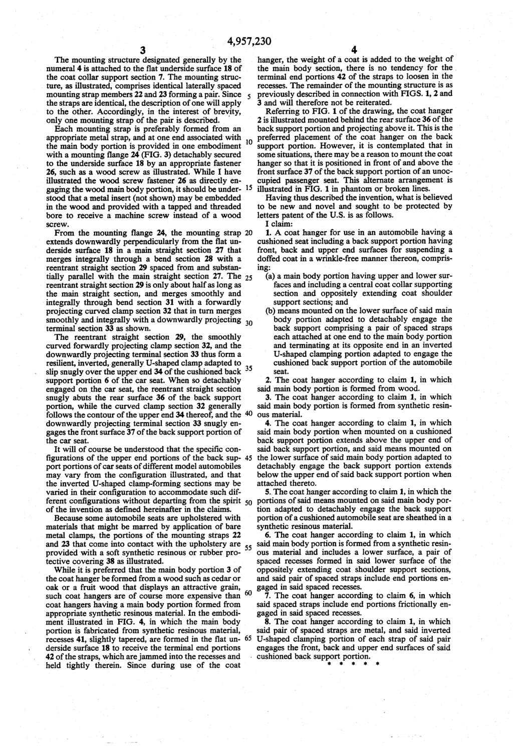
5 5 30 [0026] In the preferred embodiment, shown in FIGS. 1 and 2, the main body portion 3 is fabricated from wood, preferably cedar, but other types of wood may be used. The main body portion is formed by automatic equipment to provide a centrally disposed coat collar support section 7 having a gently curved rear surface 8 and a flat upper surface 9. [A skilled artisan will possess ample knowledge and skill in the use of such automatic equipment for forming the main body portion and therefore a precise description of the methods for doing so is considered unnecessary to this disclosure.] [0027] From the centrally disposed coat collar support section there extend in laterally opposite directions integral coat shoulder support sections 11 and 12. The coat shoulder support sections extend laterally outwardly in opposite directions and downwardly from the centrally disposed coat collar support section, the coat shoulder support sections having smooth convexly curved upper surfaces 13 and 14, respectively, terminating in smoothly rounded distal ends 16 and 17. The coat collar support portion is also provided with a flat underside 18 generally parallel with the flat upper surface 9, while the undersides 19 and 21 of the laterally extending coat shoulder support sections 11 and 12, respectively, are also flat, merging smoothly with the associated convexly curved surfaces 13 and 14, respectively. [0028] The main body portion of the coat hanger is thus configured to support a coat or jacket hung thereon in substantially the same attitude in which the coat or jacket is in when worn. The coat collar support section is configured and proportioned in size to retain the collar section of a coat or jacket extended in the same manner as when the coat is worn, while the laterally extending coat shoulder support sections support the shoulder portions of the coat in the same manner in which these coat components are supported by a wearer's shoulders. The coat or jacket may thus be draped naturally on the coat hanger and is suspended in a wrinkle-free manner. [0029] [What about alternatives for suspending pants, skirts, or other items?] [0030] The main body portion may be formed using the techniques described in U.S. Pat. No. 1,234,567, the entire contents of which is hereby incorporated by reference as if fully set forth herein. [0031] The mounting structure designated generally by the numeral 4 is attached to the flat underside surface 18 of the coat collar support section 7. The mounting structure, -5-
6 5 30 as illustrated, comprises identical laterally spaced mounting strap members 22 and 23 forming a pair. Since the straps are identical, the description of one will apply to the other. Accordingly, in the interest of brevity, only one mounting strap of the pair is described. [0032] Each mounting strap is preferably formed from an appropriate metal strap, and at one end associated with the main body portion is provided in one embodiment with a mounting flange 24 (FIG. 3) detachably secured to the underside surface 18 by an appropriate fastener 26, such as a wood screw as illustrated. While I have illustrated the wood screw fastener 26 as directly engaging the wood main body portion, it should be understood that a metal insert (not shown) may be embedded in the wood and provided with a tapped and threaded bore to receive a machine screw instead of a wood screw. [0033] From the mounting flange 24, the mounting strap extends downwardly perpendicularly from the flat underside surface 18 in a main straight section 27 that merges integrally through a bend section 28 with a reentrant straight section 29 spaced from and substantially parallel with the main straight section 27. The reentrant straight section 29 is only about half as long as the main straight section, and merges smoothly and integrally through bend section 31 with a forwardly projecting curved clamp section 32 that in turn merges smoothly and integrally with a downwardly projecting terminal section 33 as shown. [0034] The reentrant straight section 29, the smoothly curved forwardly projecting clamp section 32, and the downwardly projecting terminal section 33 thus form a resilient, inverted, generally U-shaped clamp adapted to slip snugly over the upper end 34 of the cushioned back support portion 6 of the car seat. When so detachably engaged on the car seat, the reentrant straight section snugly abuts the rear surface 36 of the back support portion, while the curved clamp section 32 generally follows the contour of the upper end 34 thereof, and the downwardly projecting terminal section 33 snugly engages the front surface 37 of the back support portion of the car seat. [0035] It will of course be understood that the specific configurations of the upper end portions of the back support portions of car seats of different model automobiles may vary from the configuration illustrated, and that the inverted U-shaped clamp-forming sections may be varied in their configuration to accommodate such different -6-
7 5 30 configurations without departing from the spirit of the invention as defined hereinafter in the claims. [0036] Because some automobile seats are upholstered with materials that might be marred by application of bare metal clamps, the portions of the mounting straps 22 and 23 that come into contact with the upholstery are provided with a soft synthetic resinous or rubber protective covering 38 as illustrated. [0037] While it is preferred that the main body portion 3 of the coat hanger be formed from a wood such as cedar or oak or a fruit wood that displays an attractive grain, such coat hangers are of course more expensive than coat hangers having a main body portion formed from appropriate synthetic resinous material. In the embodiment illustrated in FIG. 4, in which the main body portion is fabricated from synthetic resinous material, recesses 41, slightly tapered, are formed in the flat underside surface 18 to receive the terminal end portions 42 of the straps, which are jammed into the recesses and held tightly therein. Since during use of the coat hanger, the weight of a coat is added to the weight of the main body section, there is no tendency for the terminal end portions 42 of the straps to loosen in the recesses. The remainder of the mounting structure is as previously described in connection with FIGS. 1, 2 and 3 and will therefore not be reiterated. [0038] Referring to FIG. 1 of the drawing, the coat hanger 2 is illustrated mounted behind the rear surface 36 of the back support portion and projecting above it. This is the preferred placement of the coat hanger on the back support portion. However, it is contemplated that in some situations, there may be a reason to mount the coat hanger so that it is positioned in front of and above the front surface 37 of the back support portion of an unoccupied passenger seat. This alternate arrangement is illustrated in FIG. 1 in phantom or broken lines. [0039] The coat hanger apparatus described above has numerous [effects, benefits or advantages] with respect to prior approaches. For example, the apparatus enables hanging a coat in the cabin of an automobile without causing wrinkles in the garment and without occupying excessive space within the cabin. [0040] Having thus described the invention, what is believed to be new and novel and sought to be protected by letters patent of the U.S. is as follows. -7-
8 5 [0041] In the foregoing specification, the invention has been described with reference to specific embodiments thereof. It will, however, be evident that various modifications and changes may be made thereto without departing from the broader spirit and scope of the invention. The specification and drawings are, accordingly, to be regarded in an illustrative rather than a restrictive sense. CLAIMS I claim: 1. A coat hanger for use in an automobile having a cushioned seat including a back support portion having front, back and upper end surfaces for suspending a doffed coat in a wrinkle-free manner thereon, comprising: (a) a main body portion having upper and lower surfaces and including a central coat collar supporting section and oppositely extending coat shoulder support sections; and (b) means mounted on the lower surface of said main body portion adapted to detachably engage the back support comprising a pair of spaced straps each attached at one end to the main body portion and terminating at its opposite end in an inverted U-shaped clamping portion adapted to engage the cushioned back support portion of the automobile seat. 2. The coat hanger according to claim 1, in which said main body portion is formed from wood. 3. The coat hanger according to claim 1, in which said main body portion is formed from synthetic resinous material The coat hanger according to claim 1, in which said main body portion when mounted on a cushioned back support portion extends above the upper end of said back support portion, and said means mounted on the lower surface of said main body portion adapted to detachably engage the back support portion extends below the upper end of said back -8-
9 support portion when attached thereto The coat hanger according to claim 1, in which the portions of said means mounted on said main body portion adapted to detachably engage the back support portion of a cushioned automobile seat are sheathed in a synthetic resinous material. 6. The coat hanger according to claim 1, in which said main body portion is formed from a synthetic resinous material and includes a lower surface, a pair of spaced recesses formed in said lower surface of the oppositely extending coat shoulder support sections, and said pair of spaced straps include end portions engaged in said spaced recesses. 7. The coat hanger according to claim 6, in which said spaced straps include end portions frictionally engaged in said spaced recesses. 8. The coat hanger according to claim 1, in which said pair of spaced straps are metal, and said inverted U-shaped clamping portion of each strap of said pair engages the front, back and upper end surfaces of said cushioned back support portion. 9. A coat hanger, as shown and described.. A coat hanger substantially as hereinbefore described with reference to the accompanying drawings. Abstract Presented is a coat hanger providing a main body portion on which a coat may be draped in a wrinkle-free manner. The main body portion of the coat hanger is provided with a depending mounting structure that detachably clamps resiliently on the upper end portion of the back support portion of a cushioned automobile seat so that a coat hung on the coat hanger, hangs wrinkle-free behind the back support portion of the seat. -9-
10
11
12
13
14
United States Patent (19) Blanchard et al.
 Blanchard et al.") United States Patent (19) Blanchard et al. (54) (75) WISHBONE HANGER Inventors: Russell O. Blanchard; Robert A. Bredeweg, both of Zeeland, Mich. (73) Assignee: Batts, Inc., Zeeland, Mich. (21) Appl. No.:
United States Patent (19) Blanchard et al. (54) (75) WISHBONE HANGER Inventors: Russell O. Blanchard; Robert A. Bredeweg, both of Zeeland, Mich. (73) Assignee: Batts, Inc., Zeeland, Mich. (21) Appl. No.:
Universal mounting bracket for laser targeting and feedback system
 University of Northern Iowa UNI ScholarWorks Patents (University of Northern Iowa) 5-6-2003 Universal mounting bracket for laser targeting and feedback system Richard J. Kelin II Follow this and additional
Ay:44, 444-, INven TOR HARVEY R. PLUMMER. Jan. 3, 1967 H. R. PLUMMER 3,295,187. ArTws, Filed March l, Sheets-Sheet
 Jan. 3, 1967 H. R. PLUMMER Filed March l, 1965 2 Sheets-Sheet INven TOR HARVEY R. PLUMMER Ay:44, 444-, 14-42--- ArTws, Jan. 3, 1967 H. R. PUMMER Filed March 1, 1965 2. Sheets-Sheet 2 INVENTOR HARVEY R.
DISTRIBUTION STATEMENT A Approved for Public Release Distribution Unlimited
 Serial Number 09/152.477 Filing Date 11 September 1998 Inventor Anthony A. Ruffa NOTICE The above identified patent application is available for licensing. Requests for information should be addressed
NOTICE. The above identified patent application is available for licensing. Requests for information should be addressed to:
 Serial No.. Filing Date 1 July 1 Inventor Earl S. Nickerson Wayne C. Tucker NOTICE The above identified patent application is available for licensing. Requests for information should be addressed to: ÄBprovsa
United States Patent [19]
![United States Patent [19]](/thumbs/96/127589277.jpg "United States Patent [19]") United States Patent [19] Duffy [11] 3,740,846 [45] June 26, 1973 [54] SHEARS HAVING CLEARANCE ADJUSTING MEANS BETWEEN PIVOTAL COOPERATING MEMBERS [75] Inventor: William Duffy, Jamesburg, N.J. [73] Assignee:
United States Patent [19] Duffy [11] 3,740,846 [45] June 26, 1973 [54] SHEARS HAVING CLEARANCE ADJUSTING MEANS BETWEEN PIVOTAL COOPERATING MEMBERS [75] Inventor: William Duffy, Jamesburg, N.J. [73] Assignee:
(12) United States Patent (10) Patent No.: US 7.458,305 B1
 United States Patent (10) Patent No.: US 7.458,305 B1") US007458305B1 (12) United States Patent (10) Patent No.: US 7.458,305 B1 Horlander et al. (45) Date of Patent: Dec. 2, 2008 (54) MODULAR SAFE ROOM (58) Field of Classification Search... 89/36.01, 89/36.02,
US007458305B1 (12) United States Patent (10) Patent No.: US 7.458,305 B1 Horlander et al. (45) Date of Patent: Dec. 2, 2008 (54) MODULAR SAFE ROOM (58) Field of Classification Search... 89/36.01, 89/36.02,
Thursday, August 29, 2002 United States Patent: 6,065,504 Page: 1. United States Patent 6,065,504 Sidore May 23, Abstract
 Thursday, August 29, 2002 United States Patent: 6,065,504 Page: 1 ( 1 of 3 ) United States Patent 6,065,504 Sidore May 23, 2000 Portable loom Abstract A portable loom comprises a header, a spaced bottom
John J. Vaillancourt Steven L. Camara Daniel W. French NOTICE
 Serial Number Filing Date Inventor 09/152.475 11 September 1998 John J. Vaillancourt Steven L. Camara Daniel W. French NOTICE The above identified patent application is available for licensing. Requests
(12) United States Patent
 United States Patent") (12) United States Patent USOO698.6322B2 (10) Patent No.: US 6,986,322 B2 Lumpkin (45) Date of Patent: Jan. 17, 2006 (54) SQUIRREL PROOF BIRD FEEDER 4,188.913 A 2/1980 Earl et al. 4,327,669 A 5/1982 Blasbalg
(12) United States Patent USOO698.6322B2 (10) Patent No.: US 6,986,322 B2 Lumpkin (45) Date of Patent: Jan. 17, 2006 (54) SQUIRREL PROOF BIRD FEEDER 4,188.913 A 2/1980 Earl et al. 4,327,669 A 5/1982 Blasbalg
(12) United States Patent (10) Patent No.: US 8,187,032 B1
 United States Patent (10) Patent No.: US 8,187,032 B1") US008187032B1 (12) United States Patent (10) Patent No.: US 8,187,032 B1 Park et al. (45) Date of Patent: May 29, 2012 (54) GUIDED MISSILE/LAUNCHER TEST SET (58) Field of Classification Search... 439/76.1.
US008187032B1 (12) United States Patent (10) Patent No.: US 8,187,032 B1 Park et al. (45) Date of Patent: May 29, 2012 (54) GUIDED MISSILE/LAUNCHER TEST SET (58) Field of Classification Search... 439/76.1.
(12) Patent Application Publication (10) Pub. No.: US 2005/ A1
 Patent Application Publication (10) Pub. No.: US 2005/ A1") (19) United States US 20050O28668A1 (12) Patent Application Publication (10) Pub. No.: US 2005/0028668A1 Teel (43) Pub. Date: Feb. 10, 2005 (54) WRIST POSITION TRAINING ASSEMBLY (76) Inventor: Kenneth
(19) United States US 20050O28668A1 (12) Patent Application Publication (10) Pub. No.: US 2005/0028668A1 Teel (43) Pub. Date: Feb. 10, 2005 (54) WRIST POSITION TRAINING ASSEMBLY (76) Inventor: Kenneth
Triaxial fabric pattern
 United States Patent: 4,191,219 2/15/03 8:40 AM ( 1 of 1 ) United States Patent 4,191,219 Kaye March 4, 1980 Triaxial fabric pattern Abstract In the preferred embodiment, the triaxial fabric is adapted
 July 26, 1966 N. S. WATERMAN Filed July 29, 1963 2 Sheets-Sheet NNNN NaNYS3% SSSSSSSSSSSSN 33 A S4 22222222222222222222222 242S 4% as -a-mo as amo- aga 2 --------- ---------- 6 INVENTOR. Neil S. Waterman
(12) United States Patent
 United States Patent") US008133074B1 (12) United States Patent Park et al. (10) Patent No.: (45) Date of Patent: Mar. 13, 2012 (54) (75) (73) (*) (21) (22) (51) (52) GUIDED MISSILE/LAUNCHER TEST SET REPROGRAMMING INTERFACE ASSEMBLY
US008133074B1 (12) United States Patent Park et al. (10) Patent No.: (45) Date of Patent: Mar. 13, 2012 (54) (75) (73) (*) (21) (22) (51) (52) GUIDED MISSILE/LAUNCHER TEST SET REPROGRAMMING INTERFACE ASSEMBLY
(12) United States Patent (10) Patent No.: US 6,892,743 B2
 United States Patent (10) Patent No.: US 6,892,743 B2") USOO6892743B2 (12) United States Patent (10) Patent No.: US 6,892,743 B2 Armstrong et al. (45) Date of Patent: May 17, 2005 (54) MODULAR GREENHOUSE 5,010,909 A * 4/1991 Cleveland... 135/125 5,331,725 A
USOO6892743B2 (12) United States Patent (10) Patent No.: US 6,892,743 B2 Armstrong et al. (45) Date of Patent: May 17, 2005 (54) MODULAR GREENHOUSE 5,010,909 A * 4/1991 Cleveland... 135/125 5,331,725 A
United States Patent Office
 United States Patent Office 3,127,650 Patented Apr. 7, 1964 1 2 3,127,650 BUCKLES William Henry Seward, Havant, England, assignor to Kangol Helmets Limited, London, England, a British company Filed Mar.
Feb. 20, 1968 TOHCHUNG Wei 3,369,691 STACKED FOOD CONTAINERS. Filed Dec. 15, Sheets-Sheet INVENTOR. /o/7chung.
 Feb. 0, 1968 TOHCHUG Wei STACKED FOOD COTAIERS Filed Dec. 15, 1966 3. Sheets-Sheet BY /o/7chung IVETOR Wed face, 7TTIREX5 Feb. 0, 1968 Filed Dec. 15, 1966 TOHCHUG WEI STACKED FOOD COTAIERS 3. Sheets-Sheet
BEST AVAILABLE COPY. United States Patent (19) Boschetto, Jr. et al. COMBINATION TOOL INCLUDING
 Boschetto, Jr. et al. COMBINATION TOOL INCLUDING") United States Patent (19) Boschetto, Jr. et al. 54 76) 21 22 51) 52 58 COMBINATION TOOL INCLUDING SPANNER WRENCH AND SCREWDRVER Inventors: Benjamen J. Boschetto, Jr., 17685 Racoon Ct. Morgan Hill, Calif.
United States Patent (19) Boschetto, Jr. et al. 54 76) 21 22 51) 52 58 COMBINATION TOOL INCLUDING SPANNER WRENCH AND SCREWDRVER Inventors: Benjamen J. Boschetto, Jr., 17685 Racoon Ct. Morgan Hill, Calif.
(12) Patent Application Publication (10) Pub. No.: US 2017/ A1
 Patent Application Publication (10) Pub. No.: US 2017/ A1") (19) United States US 201701 01828A1 (12) Patent Application Publication (10) Pub. No.: US 2017/0101828A1 McGowan et al. (43) Pub. Date: (54) PRE-INSTALLED ANTI-ROTATION KEY (52) U.S. Cl. FOR THREADED
(19) United States US 201701 01828A1 (12) Patent Application Publication (10) Pub. No.: US 2017/0101828A1 McGowan et al. (43) Pub. Date: (54) PRE-INSTALLED ANTI-ROTATION KEY (52) U.S. Cl. FOR THREADED
(12) Patent Application Publication (10) Pub. No.: US 2005/ A1
 Patent Application Publication (10) Pub. No.: US 2005/ A1") (19) United States (12) Patent Application Publication (10) Pub. No.: US 2005/0064060 A1 Wagner et al. US 2005OO64060A1 (43) Pub. Date: Mar. 24, 2005 (54) (75) (73) (21) (22) (63) MOLDING APPARATUS FOR
(19) United States (12) Patent Application Publication (10) Pub. No.: US 2005/0064060 A1 Wagner et al. US 2005OO64060A1 (43) Pub. Date: Mar. 24, 2005 (54) (75) (73) (21) (22) (63) MOLDING APPARATUS FOR
USOO A United States Patent (19) 11 Patent Number: 5,931,325. Filipov (45) Date of Patent: Aug. 3, 1999
 11 Patent Number: 5,931,325. Filipov (45) Date of Patent: Aug. 3, 1999") USOO593 1325A United States Patent (19) 11 Patent Number: 5,931,325 Filipov (45) Date of Patent: Aug. 3, 1999 54 ADJUSTABLE MUDRING FOR Primary Examiner Steven Pollard CONVENTIONAL ELECTRICAL OUTLET BOX
USOO593 1325A United States Patent (19) 11 Patent Number: 5,931,325 Filipov (45) Date of Patent: Aug. 3, 1999 54 ADJUSTABLE MUDRING FOR Primary Examiner Steven Pollard CONVENTIONAL ELECTRICAL OUTLET BOX
United States Patent (19) Mori
 Mori") United States Patent (19) Mori 11 Patent Number: 45) Date of Patent: Dec. 3, 1991 54 PAPER-CUTTING MACHINE AND METHOD OF CUTTNG PAPER 75) Inventor: 73 Assignee: Chuzo Mori, Katsushika, Japan Carl Manufacturing
United States Patent (19) Mori 11 Patent Number: 45) Date of Patent: Dec. 3, 1991 54 PAPER-CUTTING MACHINE AND METHOD OF CUTTNG PAPER 75) Inventor: 73 Assignee: Chuzo Mori, Katsushika, Japan Carl Manufacturing
(12) United States Patent (10) Patent No.: US 6,385,876 B1
 United States Patent (10) Patent No.: US 6,385,876 B1") USOO6385876B1 (12) United States Patent (10) Patent No.: McKenzie () Date of Patent: May 14, 2002 (54) LOCKABLE LICENSE PLATE COVER 2,710,475 A 6/1955 Salzmann... /202 ASSEMBLY 3,304,642 A 2/1967 Dardis...
USOO6385876B1 (12) United States Patent (10) Patent No.: McKenzie () Date of Patent: May 14, 2002 (54) LOCKABLE LICENSE PLATE COVER 2,710,475 A 6/1955 Salzmann... /202 ASSEMBLY 3,304,642 A 2/1967 Dardis...
(12) Patent Application Publication (10) Pub. No.: US 2002/ A1
 Patent Application Publication (10) Pub. No.: US 2002/ A1") US 20020046661A1 (19) United States (12) Patent Application Publication (10) Pub. No.: US 2002/0046661 A1 Hawkins (43) Pub. Date: Apr. 25, 2002 (54) HYDRAULIC PRESS (52) U.S. Cl.... 100/269.17 (76) Inventor:
US 20020046661A1 (19) United States (12) Patent Application Publication (10) Pub. No.: US 2002/0046661 A1 Hawkins (43) Pub. Date: Apr. 25, 2002 (54) HYDRAULIC PRESS (52) U.S. Cl.... 100/269.17 (76) Inventor:
(12) Patent Application Publication (10) Pub. No.: US 2004/ A1
 Patent Application Publication (10) Pub. No.: US 2004/ A1") (19) United States US 2004O187408A1 (12) Patent Application Publication (10) Pub. No.: US 2004/0187408A1 Smith (43) Pub. Date: Sep. 30, 2004 (54) JAMB EXTENDER FOR WALL FINISHING (57) ABSTRACT SYSTEM A
(19) United States US 2004O187408A1 (12) Patent Application Publication (10) Pub. No.: US 2004/0187408A1 Smith (43) Pub. Date: Sep. 30, 2004 (54) JAMB EXTENDER FOR WALL FINISHING (57) ABSTRACT SYSTEM A
(12) United States Patent
 United States Patent") USOO7325359B2 (12) United States Patent Vetter (10) Patent No.: (45) Date of Patent: Feb. 5, 2008 (54) (75) (73) (*) (21) (22) (65) (51) (52) (58) (56) PROJECTION WINDOW OPERATOR Inventor: Gregory J. Vetter,
USOO7325359B2 (12) United States Patent Vetter (10) Patent No.: (45) Date of Patent: Feb. 5, 2008 (54) (75) (73) (*) (21) (22) (65) (51) (52) (58) (56) PROJECTION WINDOW OPERATOR Inventor: Gregory J. Vetter,
Oct. 25, ,280,665. Filed April 8, ATToRNEYs H. BLOCK. 2 Sheets-Sheet NVENTOR HAROLD BLOCK TWEEZERS
 Oct. 25, 1966 Filed April 8, 1966 H. BLOCK 2 Sheets-Sheet NVENTOR HAROLD BLOCK ATToRNEYs Oct. 25, 1966 Filed April 8, 1966 H, BLOCK 2. Sheets-Sheet 2 ZZZZZZ Taseo (7 INVENTOR HAROLD BLOCK ATTORNEYS United
(12) United States Patent (10) Patent No.: US 6,752,496 B2
 United States Patent (10) Patent No.: US 6,752,496 B2") USOO6752496 B2 (12) United States Patent (10) Patent No.: US 6,752,496 B2 Conner (45) Date of Patent: Jun. 22, 2004 (54) PLASTIC FOLDING AND TELESCOPING 5,929.966 A * 7/1999 Conner... 351/118 EYEGLASS
USOO6752496 B2 (12) United States Patent (10) Patent No.: US 6,752,496 B2 Conner (45) Date of Patent: Jun. 22, 2004 (54) PLASTIC FOLDING AND TELESCOPING 5,929.966 A * 7/1999 Conner... 351/118 EYEGLASS
HDL(M)6 Nut/Screw Assembly
6 Nut/Screw Assembly") HDL(M)6 Nut/Screw Assembly Remove, repair, and reassemble the nut and screw assembly in your HDL series double lock vise. In these instructions when we refer to the front of the vise or nut/screw assembly,
HDL(M)6 Nut/Screw Assembly Remove, repair, and reassemble the nut and screw assembly in your HDL series double lock vise. In these instructions when we refer to the front of the vise or nut/screw assembly,
PATENT AGENT EXAMINATION PAPER A. Tuesday - April 25, :00 am to 1:00 pm INSTRUCTIONS
 PATENT AGENT EXAMINATION PAPER A Tuesday - April 25, 2006-9:00 am to 1:00 pm INSTRUCTIONS You must place your assigned number on each examination paper, answer book(s) and envelope. No further identification
United States Patent 19 Clifton
 United States Patent 19 Clifton (54) TAPE MEASURING SQUARE AND ADJUSTABLE TOOL GUIDE 76 Inventor: Norman L. Clifton, 49 S. 875 West, Orem, Utah 84058-5267 21 Appl. No.: 594,082 22 Filed: Jan. 30, 1996
11 Patent Number: 5,584,458 Rando 45) Date of Patent: Dec. 17, (56) References Cited (54) SEAERS FOR U.S. PATENT DOCUMENTS
 Date of Patent: Dec. 17, (56) References Cited (54) SEAERS FOR U.S. PATENT DOCUMENTS") United States Patent (19) III IIHIIII USOO5584458A 11 Patent Number: 5,584,458 Rando 45) Date of Patent: Dec. 17, 1996 (56) References Cited (54) SEAERS FOR U.S. PATENT DOCUMENTS 4,926,722 5/1990 Sorensen
United States Patent (19) III IIHIIII USOO5584458A 11 Patent Number: 5,584,458 Rando 45) Date of Patent: Dec. 17, 1996 (56) References Cited (54) SEAERS FOR U.S. PATENT DOCUMENTS 4,926,722 5/1990 Sorensen
30 DAY PILL CUTTING DEVICE
 DN0311 30 DAY PILL CUTTING DEVICE Technical Field [001] The present invention relates to an improved pill or tablet cutting device and more particularly to a pill cutter for simultaneously cutting a plurality
(12) Patent Application Publication (10) Pub. No.: US 2012/ A1
 Patent Application Publication (10) Pub. No.: US 2012/ A1") US 20120047754A1 (19) United States (12) Patent Application Publication (10) Pub. No.: US 2012/0047754 A1 Schmitt (43) Pub. Date: Mar. 1, 2012 (54) ELECTRICSHAVER (52) U.S. Cl.... 30/527 (57) ABSTRACT
US 20120047754A1 (19) United States (12) Patent Application Publication (10) Pub. No.: US 2012/0047754 A1 Schmitt (43) Pub. Date: Mar. 1, 2012 (54) ELECTRICSHAVER (52) U.S. Cl.... 30/527 (57) ABSTRACT
United States Patent (19) 11) 3,711,874 Gajer (45) Jan. 23, 1973
 11) 3,711,874 Gajer (45) Jan. 23, 1973") United States Patent (19) 11) 3,711,874 Gajer (45) Jan. 23, 1973 54 BASKETSINK STRAINER 3,007, 179 1/1961 Bertulli... 4/287 3,096,527 7/1963 Eynon......41287 (75) Inventor: Israel Gajer, Wyandanch, N.Y.
United States Patent (19) 11) 3,711,874 Gajer (45) Jan. 23, 1973 54 BASKETSINK STRAINER 3,007, 179 1/1961 Bertulli... 4/287 3,096,527 7/1963 Eynon......41287 (75) Inventor: Israel Gajer, Wyandanch, N.Y.
(12) Patent Application Publication (10) Pub. No.: US 2013/ A1
 Patent Application Publication (10) Pub. No.: US 2013/ A1") US 2013 0334265A1 (19) United States (12) Patent Application Publication (10) Pub. No.: US 2013/0334265 A1 AVis0n et al. (43) Pub. Date: Dec. 19, 2013 (54) BRASTORAGE DEVICE Publication Classification
US 2013 0334265A1 (19) United States (12) Patent Application Publication (10) Pub. No.: US 2013/0334265 A1 AVis0n et al. (43) Pub. Date: Dec. 19, 2013 (54) BRASTORAGE DEVICE Publication Classification
(12) United States Patent (10) Patent No.: US 6,612,223 B2. Leonard et al. (45) Date of Patent: Sep. 2, 2003
 United States Patent (10) Patent No.: US 6,612,223 B2. Leonard et al. (45) Date of Patent: Sep. 2, 2003") USOO6612223B2 (12) United States Patent (10) Patent No.: US 6,612,223 B2 Leonard et al. (45) Date of Patent: Sep. 2, 2003 (54) PNEUMATIC ACTUATOR 5,178,367 A * 1/1993 Vaughen... 254/93 HP 5,461.207 A 10/1995
USOO6612223B2 (12) United States Patent (10) Patent No.: US 6,612,223 B2 Leonard et al. (45) Date of Patent: Sep. 2, 2003 (54) PNEUMATIC ACTUATOR 5,178,367 A * 1/1993 Vaughen... 254/93 HP 5,461.207 A 10/1995
United States Patent (19) Sun
 Sun") United States Patent (19) Sun 54 INFORMATION READINGAPPARATUS HAVING A CONTACT IMAGE SENSOR 75 Inventor: Chung-Yueh Sun, Tainan, Taiwan 73 Assignee: Mustek Systems, Inc., Hsinchu, Taiwan 21 Appl. No. 916,941
United States Patent (19) Sun 54 INFORMATION READINGAPPARATUS HAVING A CONTACT IMAGE SENSOR 75 Inventor: Chung-Yueh Sun, Tainan, Taiwan 73 Assignee: Mustek Systems, Inc., Hsinchu, Taiwan 21 Appl. No. 916,941
(12) United States Patent (10) Patent No.: US 6,347,876 B1
 United States Patent (10) Patent No.: US 6,347,876 B1") USOO6347876B1 (12) United States Patent (10) Patent No.: Burton (45) Date of Patent: Feb. 19, 2002 (54) LIGHTED MIRROR ASSEMBLY 1555,478 A * 9/1925 Miller... 362/141 1968,342 A 7/1934 Herbold... 362/141
USOO6347876B1 (12) United States Patent (10) Patent No.: Burton (45) Date of Patent: Feb. 19, 2002 (54) LIGHTED MIRROR ASSEMBLY 1555,478 A * 9/1925 Miller... 362/141 1968,342 A 7/1934 Herbold... 362/141
United States Patent (19) Prizzi
 Prizzi") United States Patent (19) Prizzi (54) TOWEL HOLDER 76 Inventor: Darin Prizzi, 8416 Mantanzas Rd., Fort Myers, Fla. 33912 (21) Appl. No.: 491,820 (22 Filed: Jun. 19, 1995 (51) Int. Cl.... A47H 13/00 (52)
United States Patent (19) Prizzi (54) TOWEL HOLDER 76 Inventor: Darin Prizzi, 8416 Mantanzas Rd., Fort Myers, Fla. 33912 (21) Appl. No.: 491,820 (22 Filed: Jun. 19, 1995 (51) Int. Cl.... A47H 13/00 (52)
(12) United States Patent (10) Patent No.: US 6,345,454 B1
 United States Patent (10) Patent No.: US 6,345,454 B1") USOO634.5454B1 (12) United States Patent (10) Patent No. Cotton (45) Date of Patent Feb. 12, 2002 (54) SHOE HAVING AREMOVABLE SOLE AND 5,661,915. A 9/1997 Smith... 36/15 METHOD OF USE * cited by examiner
USOO634.5454B1 (12) United States Patent (10) Patent No. Cotton (45) Date of Patent Feb. 12, 2002 (54) SHOE HAVING AREMOVABLE SOLE AND 5,661,915. A 9/1997 Smith... 36/15 METHOD OF USE * cited by examiner
William H. Nedderman, Jr. NOTICE. The above identified patent application is available for licensing. Requests for information should be addressed to:
 _ _ Serial Number Filing Date Inventor 09/332,407 14 June 1999 William H. Nedderman, Jr. NOTICE The above identified patent application is available for licensing. Requests for information should be addressed
(12) Patent Application Publication (10) Pub. No.: US 2005/ A1
 Patent Application Publication (10) Pub. No.: US 2005/ A1") (19) United States US 2005O268559A1 (12) Patent Application Publication (10) Pub. No.: US 2005/0268559 A1 Ellingson (43) Pub. Date: (54) ROLLABLE DOOR SEAL WITH INTEGRAL NTUMESCENT STRIPS (76) Inventor:
(19) United States US 2005O268559A1 (12) Patent Application Publication (10) Pub. No.: US 2005/0268559 A1 Ellingson (43) Pub. Date: (54) ROLLABLE DOOR SEAL WITH INTEGRAL NTUMESCENT STRIPS (76) Inventor:
(12) United States Patent (10) Patent No.: US 6,205,585 B1
 United States Patent (10) Patent No.: US 6,205,585 B1") USOO6205585B1 (12) United States Patent (10) Patent No.: Capparelli (45) Date of Patent: *Mar. 27, 2001 (54) ADJUSTABLE GARMENT 1,632,137 6/1927 Jackson... 450/32 1927,018 9/1933 Bloom... 450/32 (75) Inventor:
USOO6205585B1 (12) United States Patent (10) Patent No.: Capparelli (45) Date of Patent: *Mar. 27, 2001 (54) ADJUSTABLE GARMENT 1,632,137 6/1927 Jackson... 450/32 1927,018 9/1933 Bloom... 450/32 (75) Inventor:
(12) United States Patent
 United States Patent") (12) United States Patent Mack USOO686.0488B2 (10) Patent No.: (45) Date of Patent: Mar. 1, 2005 (54) DRILL CHUCK WITH FRONT-END SHIELD (75) Inventor: Hans-Dieter Mack, Sontheim (DE) (73) Assignee: Rohm
(12) United States Patent Mack USOO686.0488B2 (10) Patent No.: (45) Date of Patent: Mar. 1, 2005 (54) DRILL CHUCK WITH FRONT-END SHIELD (75) Inventor: Hans-Dieter Mack, Sontheim (DE) (73) Assignee: Rohm
United States Patent (19) Eve
 Eve") United States Patent (19) Eve 54. FOLDING BED AND CABINET 76 Inventor: Melvin E. Eve, 1711 Anchovy Ave., San Pedro, Calif. 90732 21 Appl. No.: 58,242 22 Filed: Jun. 4, 1987 51) Int. Cl'... A47C 19/06 52
United States Patent (19) Eve 54. FOLDING BED AND CABINET 76 Inventor: Melvin E. Eve, 1711 Anchovy Ave., San Pedro, Calif. 90732 21 Appl. No.: 58,242 22 Filed: Jun. 4, 1987 51) Int. Cl'... A47C 19/06 52
United States Patent (19) 11 Patent Number: 5,711,560 Gilbertson 45) Date of Patent: Jan. 27, 1998
 11 Patent Number: 5,711,560 Gilbertson 45) Date of Patent: Jan. 27, 1998") USOO571 1560A d United States Patent (19) 11 Patent Number: 5,711,560 Gilbertson 45) Date of Patent: Jan. 27, 1998 54) DOOR SECURITY WEDGE 5,056,836 10/1991 Wells... 292/288 5,217.269 6/1993 Wiltberger......
USOO571 1560A d United States Patent (19) 11 Patent Number: 5,711,560 Gilbertson 45) Date of Patent: Jan. 27, 1998 54) DOOR SECURITY WEDGE 5,056,836 10/1991 Wells... 292/288 5,217.269 6/1993 Wiltberger......
(12) Patent Application Publication (10) Pub. No.: US 2003/ A1
 Patent Application Publication (10) Pub. No.: US 2003/ A1") (19) United States US 2003OO66259A1 (12) Patent Application Publication (10) Pub. No.: US 2003/0066259 A1 Sudweeks (43) Pub. Date: Apr. 10, 2003 (54) FASTENER SYSTEMAND METHOD FOR ATTACHING MANUFACTURED
(19) United States US 2003OO66259A1 (12) Patent Application Publication (10) Pub. No.: US 2003/0066259 A1 Sudweeks (43) Pub. Date: Apr. 10, 2003 (54) FASTENER SYSTEMAND METHOD FOR ATTACHING MANUFACTURED
(12) United States Patent (10) Patent No.: US 6,663,057 B2
 United States Patent (10) Patent No.: US 6,663,057 B2") USOO6663057B2 (12) United States Patent (10) Patent No.: US 6,663,057 B2 Garelick et al. (45) Date of Patent: Dec. 16, 2003 (54) ADJUSTABLE PEDESTAL FOR BOAT 5,297.849 A * 3/1994 Chancellor... 297/344.
USOO6663057B2 (12) United States Patent (10) Patent No.: US 6,663,057 B2 Garelick et al. (45) Date of Patent: Dec. 16, 2003 (54) ADJUSTABLE PEDESTAL FOR BOAT 5,297.849 A * 3/1994 Chancellor... 297/344.
(12) Patent Application Publication (10) Pub. No.: US 2006/ A1
 Patent Application Publication (10) Pub. No.: US 2006/ A1") US 20060253959A1 (19) United States (12) Patent Application Publication (10) Pub. No.: US 2006/0253959 A1 Chang (43) Pub. Date: Nov. 16, 2006 (54) VERSATILESCARF (52) U.S. Cl.... 2/207 (76) Inventor: Lily
US 20060253959A1 (19) United States (12) Patent Application Publication (10) Pub. No.: US 2006/0253959 A1 Chang (43) Pub. Date: Nov. 16, 2006 (54) VERSATILESCARF (52) U.S. Cl.... 2/207 (76) Inventor: Lily
Y 6a W SES. (12) Patent Application Publication (10) Pub. No.: US 2005/ A1. (19) United States. Belinda et al. (43) Pub. Date: Nov.
 Patent Application Publication (10) Pub. No.: US 2005/ A1. (19) United States. Belinda et al. (43) Pub. Date: Nov.") (19) United States US 2005O2521.52A1 (12) Patent Application Publication (10) Pub. No.: Belinda et al. (43) Pub. Date: Nov. 17, 2005 (54) STEELTRUSS FASTENERS FOR MULTI-POSITIONAL INSTALLATION (76) Inventors:
(19) United States US 2005O2521.52A1 (12) Patent Application Publication (10) Pub. No.: Belinda et al. (43) Pub. Date: Nov. 17, 2005 (54) STEELTRUSS FASTENERS FOR MULTI-POSITIONAL INSTALLATION (76) Inventors:
"4-(2- Feb. 15, 1966 H. F. YOUNG 3,235,290 GLASS LINED FITTING AND PROCESS FOR. Filed Dec. 7, Sheets-Sheet 1 GLASS LINING OF PIPE FITTING
 Feb. 15, 1966 H. F. YOUNG GLASS LINED FITTING AND PROCESS FOR GLASS LINING OF PIPE FITTING Filed Dec. 7, 1960 2. Sheets-Sheet 1 INVENTOR. HERBERT F YOUWG "4-(2- A T TO RAVE YS Feb. 15, 1966 H. F. YOUNG
United States Patent (19) Lund
 Lund") United States Patent (19) Lund 54 BROACHING CUTTER 76 Inventor: David R. Lund, 1823 Cornish Ave., Charleston, S.C. 29412 21 Appl. No.: 903,157 22 Filed: Jul. 30, 1997 Related U.S. Application Data 62 Division
United States Patent (19) Lund 54 BROACHING CUTTER 76 Inventor: David R. Lund, 1823 Cornish Ave., Charleston, S.C. 29412 21 Appl. No.: 903,157 22 Filed: Jul. 30, 1997 Related U.S. Application Data 62 Division
III IIII. United States Patent (19) Hamilton et al. application of welds thereto for attaching the hub member to
 Hamilton et al. application of welds thereto for attaching the hub member to") United States Patent (19) Hamilton et al. 54) EARTH SCREW ANCHOR ASSEMBLY HAVING ENHANCED PENETRATING CAPABILITY (75) Inventors: Daniel V. Hamilton; Robert M. Hoyt, both of Centralia; Patricia J. Halferty,
United States Patent (19) Hamilton et al. 54) EARTH SCREW ANCHOR ASSEMBLY HAVING ENHANCED PENETRATING CAPABILITY (75) Inventors: Daniel V. Hamilton; Robert M. Hoyt, both of Centralia; Patricia J. Halferty,
(12) Patent Application Publication (10) Pub. No.: US 2006/ A1
 Patent Application Publication (10) Pub. No.: US 2006/ A1") US 2006004.4273A1 (19) United States (12) Patent Application Publication (10) Pub. No.: US 2006/0044273 A1 Numazawa et al. (43) Pub. Date: Mar. 2, 2006 (54) MOUSE-TYPE INPUT DEVICE (30) Foreign Application
US 2006004.4273A1 (19) United States (12) Patent Application Publication (10) Pub. No.: US 2006/0044273 A1 Numazawa et al. (43) Pub. Date: Mar. 2, 2006 (54) MOUSE-TYPE INPUT DEVICE (30) Foreign Application
Hsu (45) Date of Patent: Jul. 27, PICTURE FRAME Primary Examiner-Kenneth J. Dorner. Assistant Examiner-Brian K. Green
 Date of Patent: Jul. 27, PICTURE FRAME Primary Examiner-Kenneth J. Dorner. Assistant Examiner-Brian K. Green") III United States Patent (19) 11) US005230172A Patent Number: 5,230,172 Hsu (45) Date of Patent: Jul. 27, 1993 54 PICTURE FRAME Primary Examiner-Kenneth J. Dorner o Assistant Examiner-Brian K. Green 76)
III United States Patent (19) 11) US005230172A Patent Number: 5,230,172 Hsu (45) Date of Patent: Jul. 27, 1993 54 PICTURE FRAME Primary Examiner-Kenneth J. Dorner o Assistant Examiner-Brian K. Green 76)
(12) United States Patent (10) Patent No.: US 6,890,073 B2
 United States Patent (10) Patent No.: US 6,890,073 B2") USOO6890O73B2 (12) United States Patent (10) Patent No.: US 6,890,073 B2 DiChiara et al. (45) Date of Patent: May 10, 2005 (54) IMPACT RESISTANT EYE WEAR FRAME FR 592.096 4/1925 ASSEMBLY HAVING ASPLT FRAME
USOO6890O73B2 (12) United States Patent (10) Patent No.: US 6,890,073 B2 DiChiara et al. (45) Date of Patent: May 10, 2005 (54) IMPACT RESISTANT EYE WEAR FRAME FR 592.096 4/1925 ASSEMBLY HAVING ASPLT FRAME
A Practical Guide to Free Energy Devices
 A Practical Guide to Free Energy Devices Device Patent No 30: Last updated: 24th June 2007 Author: Patrick J. Kelly This patent shows a method of altering a standard electrical generator intended to be
EC How to Make Slipcovers
 University of Nebraska - Lincoln DigitalCommons@University of Nebraska - Lincoln Historical Materials from University of Nebraska- Lincoln Extension Extension 1984 EC84-410 How to Make Slipcovers Margaret
(12) United States Patent
 United States Patent") (12) United States Patent USOO900.4986B2 (10) Patent No.: US 9,004,986 B2 Byers (45) Date of Patent: Apr. 14, 2015 (54) SHARPENING TOOL (58) Field of Classification Search USPC... 451/557; 76/82, 86, 88
(12) United States Patent USOO900.4986B2 (10) Patent No.: US 9,004,986 B2 Byers (45) Date of Patent: Apr. 14, 2015 (54) SHARPENING TOOL (58) Field of Classification Search USPC... 451/557; 76/82, 86, 88
(12) Patent Application Publication (10) Pub. No.: US 2007/ A1
 Patent Application Publication (10) Pub. No.: US 2007/ A1") (19) United States US 2007025 1096A1 (12) Patent Application Publication (10) Pub. No.: US 2007/0251096 A1 Smith (43) Pub. Date: Nov. 1, 2007 (54) EGG BREAKING DEVICE INCORPORATING A DURABLE AND RUBBERIZED
(19) United States US 2007025 1096A1 (12) Patent Application Publication (10) Pub. No.: US 2007/0251096 A1 Smith (43) Pub. Date: Nov. 1, 2007 (54) EGG BREAKING DEVICE INCORPORATING A DURABLE AND RUBBERIZED
(12) United States Patent (10) Patent No.: US 6,848,291 B1
 United States Patent (10) Patent No.: US 6,848,291 B1") USOO684.8291B1 (12) United States Patent (10) Patent No.: US 6,848,291 B1 Johnson et al. (45) Date of Patent: Feb. 1, 2005 (54) PRESS BRAKE TOOL AND TOOL HOLDER FOREIGN PATENT DOCUMENTS (75) Inventors:
USOO684.8291B1 (12) United States Patent (10) Patent No.: US 6,848,291 B1 Johnson et al. (45) Date of Patent: Feb. 1, 2005 (54) PRESS BRAKE TOOL AND TOOL HOLDER FOREIGN PATENT DOCUMENTS (75) Inventors:
(12) Patent Application Publication (10) Pub. No.: US 2015/ A1
 Patent Application Publication (10) Pub. No.: US 2015/ A1") (19) United States US 2015 0311941A1 (12) Patent Application Publication (10) Pub. No.: US 2015/0311941 A1 Sorrentino (43) Pub. Date: Oct. 29, 2015 (54) MOBILE DEVICE CASE WITH MOVABLE Publication Classification
(19) United States US 2015 0311941A1 (12) Patent Application Publication (10) Pub. No.: US 2015/0311941 A1 Sorrentino (43) Pub. Date: Oct. 29, 2015 (54) MOBILE DEVICE CASE WITH MOVABLE Publication Classification
April 1, 1969 W. JONAs ET AL 3,435,988. PAPER Cup DISPENSER. Filed March 20, 1968 Sheet / of 2 N S. INVENTORs WALTER JONAS. ADOLF PFUND. ATTORNEY.
 April 1, 1969 W. JONAs ET AL. PAPER Cup DISPENSER Filed March 20, 1968 Sheet / of 2 N S. N ) INVENTORs WALTER JONAS. ADOLF PFUND. ATTORNEY. April 1, 1969 filed March 20, 1968 Sºzzzzzzzz!,, ~~~~ FIG 5.
IIIHIIII. United States Patent (19) Tannenbaum
 Tannenbaum") United States Patent (19) Tannenbaum (54) ROTARY SHAKER WITH FLEXIBLE STRAP SUSPENSION 75) Inventor: Myron Tannenbaum, Cranbury, N.J. 73) Assignee: New Brunswick Scientific Co., Inc., Edison, N.J. 21 Appl.
United States Patent (19) Tannenbaum (54) ROTARY SHAKER WITH FLEXIBLE STRAP SUSPENSION 75) Inventor: Myron Tannenbaum, Cranbury, N.J. 73) Assignee: New Brunswick Scientific Co., Inc., Edison, N.J. 21 Appl.
(12) Patent Application Publication (10) Pub. No.: US 2012/ A1
 Patent Application Publication (10) Pub. No.: US 2012/ A1") (19) United States US 20120202410A1 (12) Patent Application Publication (10) Pub. No.: US 2012/0202410 A1 Byers (43) Pub. Date: Aug. 9, 2012 54) SHARPENING TOOL Publication Classification (76) Inventor:
(19) United States US 20120202410A1 (12) Patent Application Publication (10) Pub. No.: US 2012/0202410 A1 Byers (43) Pub. Date: Aug. 9, 2012 54) SHARPENING TOOL Publication Classification (76) Inventor:
(12) United States Patent (10) Patent No.: US 7,654,911 B2
 United States Patent (10) Patent No.: US 7,654,911 B2") USOO7654911B2 (12) United States Patent (10) Patent o.: US 7,654,911 B2 Cartwright (45) Date of Patent: Feb. 2, 2010 (54) POOL TABLE LEVELIG SYSTEM 3,080,835 A * 3/1963 Guglielmi... 108,116 3,190.405 A
USOO7654911B2 (12) United States Patent (10) Patent o.: US 7,654,911 B2 Cartwright (45) Date of Patent: Feb. 2, 2010 (54) POOL TABLE LEVELIG SYSTEM 3,080,835 A * 3/1963 Guglielmi... 108,116 3,190.405 A
(12) United States Patent
 United States Patent") USOO6997795B2 (12) United States Patent Friel, Sr. (10) Patent No.: (45) Date of Patent: Feb. 14, 2006 (54) VERSATILE MANUAL SCISSOR SHARPENER (75) Inventor: Daniel D. Friel, Sr., Greenville, DE (US) (73)
USOO6997795B2 (12) United States Patent Friel, Sr. (10) Patent No.: (45) Date of Patent: Feb. 14, 2006 (54) VERSATILE MANUAL SCISSOR SHARPENER (75) Inventor: Daniel D. Friel, Sr., Greenville, DE (US) (73)
(12) United States Patent (10) Patent No.: US 6,224,230 B1
 United States Patent (10) Patent No.: US 6,224,230 B1") USOO622423OB1 (12) United States Patent (10) Patent No.: US 6,224,230 B1 Roegiers (45) Date of Patent: May 1, 2001 (54) ORNAMENT LIGHTING APPARATUS 3,655,495 4/1972 Carrell... 161/16 3,694,648 * 9/1972
USOO622423OB1 (12) United States Patent (10) Patent No.: US 6,224,230 B1 Roegiers (45) Date of Patent: May 1, 2001 (54) ORNAMENT LIGHTING APPARATUS 3,655,495 4/1972 Carrell... 161/16 3,694,648 * 9/1972
Warp length compensator for a triaxial weaving machine
 United States Patent: 4,170,249 2/15/03 8:18 AM ( 1 of 1 ) United States Patent 4,170,249 Trost October 9, 1979 Warp length compensator for a triaxial weaving machine Abstract A fixed cam located between
(12) Patent Application Publication (10) Pub. No.: US 2012/ A1
 Patent Application Publication (10) Pub. No.: US 2012/ A1") US 20120312936A1 (19) United States (12) Patent Application Publication (10) Pub. No.: US 2012/0312936A1 HUANG (43) Pub. Date: Dec. 13, 2012 (54) HOLDING DEVICE OF TABLET ELECTRONIC DEVICE (52) U.S. Cl....
US 20120312936A1 (19) United States (12) Patent Application Publication (10) Pub. No.: US 2012/0312936A1 HUANG (43) Pub. Date: Dec. 13, 2012 (54) HOLDING DEVICE OF TABLET ELECTRONIC DEVICE (52) U.S. Cl....
United States Patent (19)
") United States Patent (19) Strandberg 54 SUCKER ROD FITTING 75 Inventor: Donald G. Strandberg, Park Forest, Ill. 73) Assignee: Park-Ohio Industries, Inc., Cleveland, Ohio (21) Appl. No.: 482,800 22 Filed:
United States Patent (19) Strandberg 54 SUCKER ROD FITTING 75 Inventor: Donald G. Strandberg, Park Forest, Ill. 73) Assignee: Park-Ohio Industries, Inc., Cleveland, Ohio (21) Appl. No.: 482,800 22 Filed:
United States Patent (19)
") United States Patent (19) US00564117OA 11 Patent Number: 5,641,170 Helm 45 Date of Patent: Jun. 24, 1997 54 76) 21 22 51 52 58 PORTABLE TOOL CARRER AND DISPLAY BOX Inventor: Paul E. Helm, 2028 Ridge Rd.,
United States Patent (19) US00564117OA 11 Patent Number: 5,641,170 Helm 45 Date of Patent: Jun. 24, 1997 54 76) 21 22 51 52 58 PORTABLE TOOL CARRER AND DISPLAY BOX Inventor: Paul E. Helm, 2028 Ridge Rd.,
(12) United States Patent (10) Patent No.: US 6,729,834 B1
 United States Patent (10) Patent No.: US 6,729,834 B1") USOO6729834B1 (12) United States Patent (10) Patent No.: US 6,729,834 B1 McKinley (45) Date of Patent: May 4, 2004 (54) WAFER MANIPULATING AND CENTERING 5,788,453 A * 8/1998 Donde et al.... 414/751 APPARATUS
USOO6729834B1 (12) United States Patent (10) Patent No.: US 6,729,834 B1 McKinley (45) Date of Patent: May 4, 2004 (54) WAFER MANIPULATING AND CENTERING 5,788,453 A * 8/1998 Donde et al.... 414/751 APPARATUS
United States Patent 19
 United States Patent 19 Swayney et al. USOO5743074A 11 Patent Number: 45 Date of Patent: Apr. 28, 1998 54) 76) 21) 22 51 (52) 58 LAWN MOWER DECK PROTECTING DEVICE Inventors: Ernest Edward Swayney; Norman
(12) Patent Application Publication (10) Pub. No.: US 2006/ A1
 Patent Application Publication (10) Pub. No.: US 2006/ A1") US 20060289577A1 (19) United States (12) Patent Application Publication (10) Pub. No.: US 2006/0289577 A1 Malone (43) Pub. Date: Dec. 28, 2006 (54) UNIVERSAL ATTACHMENT SYSTEM (52) U.S. Cl.... 224/323;
US 20060289577A1 (19) United States (12) Patent Application Publication (10) Pub. No.: US 2006/0289577 A1 Malone (43) Pub. Date: Dec. 28, 2006 (54) UNIVERSAL ATTACHMENT SYSTEM (52) U.S. Cl.... 224/323;
United States Patent (19) Cobb
 Cobb") United States Patent (19) Cobb 54 RAM-SHEAR AND SLIP DEVICE FOR WELL PIPE 75 Inventor: 73) Assignee: A. Tom Cobb, Seabrook, Tex. Continental Oil Company, Ponca City, Okla. 21 Appl. No.: 671,464 22 Filed:
United States Patent (19) Cobb 54 RAM-SHEAR AND SLIP DEVICE FOR WELL PIPE 75 Inventor: 73) Assignee: A. Tom Cobb, Seabrook, Tex. Continental Oil Company, Ponca City, Okla. 21 Appl. No.: 671,464 22 Filed:
Feb. 7, R. DOPYERA 1896,484
 Feb. 7, 1933. R. DPYERA 1896,484 MUSICAL ISTRUMET Filed Feb. 1, 1932 2 Sheets-Sheet l Z2ZZZZZZZZZz7 SAVera S as - SSA; S S. S s IVETR. Rudolph Dopyera. 5 ATTREY. Feb. 7, 1933. R. DPYERA MUSICAL ISTRUMET
(12) United States Patent
 United States Patent") (12) United States Patent US007124695B2 (10) Patent No.: US 7,124.695 B2 Buechler (45) Date of Patent: Oct. 24, 2006 (54) MODULAR SHELVING SYSTEM 4,635,564 A 1/1987 Baxter 4,685,576 A 8, 1987 Hobson (76)
(12) United States Patent US007124695B2 (10) Patent No.: US 7,124.695 B2 Buechler (45) Date of Patent: Oct. 24, 2006 (54) MODULAR SHELVING SYSTEM 4,635,564 A 1/1987 Baxter 4,685,576 A 8, 1987 Hobson (76)
(12) United States Patent (10) Patent No.: US 7,673,879 B2
 United States Patent (10) Patent No.: US 7,673,879 B2") USOO7673879B2 (12) United States Patent (10) Patent No.: US 7,673,879 B2 Collings (45) Date of Patent: Mar. 9, 2010 (54) ARMSUPPORT FORA GAMING MACHINE 5,756,184 A * 5/1998 Yates... 428,188 6,347,796 B1*
USOO7673879B2 (12) United States Patent (10) Patent No.: US 7,673,879 B2 Collings (45) Date of Patent: Mar. 9, 2010 (54) ARMSUPPORT FORA GAMING MACHINE 5,756,184 A * 5/1998 Yates... 428,188 6,347,796 B1*
1,502, Boaz, only 22, MARIONETTE M. M. DONDO 27 A/ %- - IA WEATOR
 only 22, 1924. t M. M. DONDO MARIONETTE Filed July 1, 1922 3. Sheets-Sheet l - IA WEATOR s alfull-.. 27 Boaz, 27 A/ %- Y.f iii).* d July 22, 1924 e M. M. DONDO MARIONETTE Filled July l, 1922 3 Sheets-Sheet
(12) United States Patent (10) Patent No.: US 9.282,841 B1
 United States Patent (10) Patent No.: US 9.282,841 B1") USOO9282841B1 (12) United States Patent (10) Patent No.: US 9.282,841 B1 Blair (45) Date of Patent: Mar. 15, 2016 (54) ELECTRONICTABLET MOUNT 4,184.725 A * 1/1980 Spangler... 312/233 4,269,381 A * 5/1981
USOO9282841B1 (12) United States Patent (10) Patent No.: US 9.282,841 B1 Blair (45) Date of Patent: Mar. 15, 2016 (54) ELECTRONICTABLET MOUNT 4,184.725 A * 1/1980 Spangler... 312/233 4,269,381 A * 5/1981
Hinged locking mechanism
 of 8 ( 2 of 3 ) 11/6/2014 6:50 PM United States Patent 5,444,998 James August 29, 1995 Hinged locking mechanism **Please see images for: ( Certificate of Correction ) ** Abstract A hinged locking mechanism
52 U.S. Cl /587, 206/592: 229/87.02 planar Surfaces on which imprinting can appear. The molded
 USOO5806683A United States Patent (19) 11 Patent Number: Gale (45) Date of Patent: Sep. 15, 1998 54 WRAPPED PACKAGE AND METHOD USING Primary Examiner Paul T. Sewell MOLDED FIBER INNER STRUCTURE ASSistant
(12) Patent Application Publication (10) Pub. No.: US 2003/ A1
 Patent Application Publication (10) Pub. No.: US 2003/ A1") (19) United States US 2003OO3OO63A1 (12) Patent Application Publication (10) Pub. No.: US 2003/0030063 A1 Sosniak et al. (43) Pub. Date: Feb. 13, 2003 (54) MIXED COLOR LEDS FOR AUTO VANITY MIRRORS AND
(19) United States US 2003OO3OO63A1 (12) Patent Application Publication (10) Pub. No.: US 2003/0030063 A1 Sosniak et al. (43) Pub. Date: Feb. 13, 2003 (54) MIXED COLOR LEDS FOR AUTO VANITY MIRRORS AND
(12) Patent Application Publication (10) Pub. No.: US 2015/ A1
 Patent Application Publication (10) Pub. No.: US 2015/ A1") (19) United States US 2015031.6791A1 (12) Patent Application Publication (10) Pub. No.: US 2015/0316791 A1 LACHAMBRE et al. (43) Pub. Date: (54) EYEWEAR WITH INTERCHANGEABLE ORNAMENT MOUNTING SYSTEM, ORNAMENT
(19) United States US 2015031.6791A1 (12) Patent Application Publication (10) Pub. No.: US 2015/0316791 A1 LACHAMBRE et al. (43) Pub. Date: (54) EYEWEAR WITH INTERCHANGEABLE ORNAMENT MOUNTING SYSTEM, ORNAMENT
(12) Patent Application Publication (10) Pub. No.: US 2004/ A1
 Patent Application Publication (10) Pub. No.: US 2004/ A1") (19) United States US 2004.0002408A1 (12) Patent Application Publication (10) Pub. No.: US 2004/0002408 A1 Rigas (43) Pub. Date: Jan. 1, 2004 (54) VIRTUAL JUMPROPE DEVICE (76) Inventor: Peter E. Rigas,
(19) United States US 2004.0002408A1 (12) Patent Application Publication (10) Pub. No.: US 2004/0002408 A1 Rigas (43) Pub. Date: Jan. 1, 2004 (54) VIRTUAL JUMPROPE DEVICE (76) Inventor: Peter E. Rigas,
(12) Patent Application Publication (10) Pub. No.: US 2013/ A1
 Patent Application Publication (10) Pub. No.: US 2013/ A1") (19) United States (12) Patent Application Publication (10) Pub. No.: US 2013/0081252 A1 Markgraf et al. US 2013 0081252A1 (43) Pub. Date: Apr. 4, 2013 (54) ARRANGEMENT FOR FIXINGA COMPONENT INSIDE OF
(19) United States (12) Patent Application Publication (10) Pub. No.: US 2013/0081252 A1 Markgraf et al. US 2013 0081252A1 (43) Pub. Date: Apr. 4, 2013 (54) ARRANGEMENT FOR FIXINGA COMPONENT INSIDE OF
(12) United States Patent (10) Patent No.: US 6,884,014 B2. Stone et al. (45) Date of Patent: Apr. 26, 2005
 United States Patent (10) Patent No.: US 6,884,014 B2. Stone et al. (45) Date of Patent: Apr. 26, 2005") USOO6884O14B2 (12) United States Patent (10) Patent No.: Stone et al. (45) Date of Patent: Apr. 26, 2005 (54) TOLERANCE COMPENSATING MOUNTING 4,682,906. A 7/1987 Ruckert et al.... 403/409.1 DEVICE 4,846,614
USOO6884O14B2 (12) United States Patent (10) Patent No.: Stone et al. (45) Date of Patent: Apr. 26, 2005 (54) TOLERANCE COMPENSATING MOUNTING 4,682,906. A 7/1987 Ruckert et al.... 403/409.1 DEVICE 4,846,614
(12) United States Patent (10) Patent No.: US 7,805,823 B2. Sembritzky et al. (45) Date of Patent: Oct. 5, 2010
 United States Patent (10) Patent No.: US 7,805,823 B2. Sembritzky et al. (45) Date of Patent: Oct. 5, 2010") US007805823B2 (12) United States Patent (10) Patent No.: US 7,805,823 B2 Sembritzky et al. (45) Date of Patent: Oct. 5, 2010 (54) AXIAL SWAGE ALIGNMENT TOOL (56) References Cited (75) Inventors: David
US007805823B2 (12) United States Patent (10) Patent No.: US 7,805,823 B2 Sembritzky et al. (45) Date of Patent: Oct. 5, 2010 (54) AXIAL SWAGE ALIGNMENT TOOL (56) References Cited (75) Inventors: David
CHAIR COVER AND PILLOW A. 1 Front. 2 Side. 3 Arm Front. 4 Skirt Front. 5 Back. 6 Pillow CUTTING LAYOUTS CHAIR COVER AND PILLOW A
 ## PATTERN PIECES 4069 McCALL'S CRAFTS CHAIR COVER AND PILLOW A 1 Front 2 Side CHAIR COVER C,D 7 Guide PAGE 1 of 6 3 Arm Front 4 Skirt Front 5 Back 6 Pillow CUTTING LAYOUTS Cut other pieces first, allowing
United States Patent (19) Bowman
 Bowman") United States Patent (19) Bowman 54) 76) 22 21 (52) 51 (58 (56) FIRE HYDRANT LOCKING DEVICE Inventor: Harold M. Bowman, 29355 Ranney Parkway, Cleveland, Ohio 44145 Filed: June 16, 1976 Appl. No.: 696,757
United States Patent (19) Bowman 54) 76) 22 21 (52) 51 (58 (56) FIRE HYDRANT LOCKING DEVICE Inventor: Harold M. Bowman, 29355 Ranney Parkway, Cleveland, Ohio 44145 Filed: June 16, 1976 Appl. No.: 696,757
J. H. BOURGON WINDOW REGULATOR INVENTOR. VO5AA/ AyasoA6GO/y
 Feb. 8, 1927. J. H. BOURGON WINDOW REGULATOR Filed June 28, 1923 Sheets-Sheet l INVENTOR VO5AA/ AyasoA6GO/y BY Ed Feb. 8, 1927.... J. H. BOURGON WINDOW REGULATOR Filed June 28, 1923 2 Sheets-Sheet 2 N
(12) United States Patent (10) Patent No.: US 6,705,355 B1
 United States Patent (10) Patent No.: US 6,705,355 B1") USOO670.5355B1 (12) United States Patent (10) Patent No.: US 6,705,355 B1 Wiesenfeld (45) Date of Patent: Mar. 16, 2004 (54) WIRE STRAIGHTENING AND CUT-OFF (56) References Cited MACHINE AND PROCESS NEAN
USOO670.5355B1 (12) United States Patent (10) Patent No.: US 6,705,355 B1 Wiesenfeld (45) Date of Patent: Mar. 16, 2004 (54) WIRE STRAIGHTENING AND CUT-OFF (56) References Cited MACHINE AND PROCESS NEAN
ADJUSTABLE CUTTING TOOL HOLDER INVENTORS WILLIAM LEE STEINHOUR Goneaway Lane Glenarm, Illinois DREW WEST
 Patent Application ADJUSTABLE CUTTING TOOL HOLDER INVENTORS WILLIAM LEE STEINHOUR 111 11946 Goneaway Lane Glenarm, Illinois 62536 DREW WEST 5201 South Hutchinson Ct. Battlefield, Missouri 69619 STEVE HONEYCUTT
Spring connection device and assembly in a jacquard harness
 Thursday, December 27, 2001 United States Patent: 6,302,154 Page: 1 ( 6 of 266 ) United States Patent 6,302,154 Bassi, et al. October 16, 2001 Spring connection device and assembly in a jacquard harness
EP A1 (19) (11) EP A1 (12) EUROPEAN PATENT APPLICATION. (43) Date of publication: Bulletin 2010/50
 (11) EP A1 (12) EUROPEAN PATENT APPLICATION. (43) Date of publication: Bulletin 2010/50") (19) (12) EUROPEAN PATENT APPLICATION (11) EP 2 261 890 A1 (43) Date of publication: 15.12.20 Bulletin 20/50 (51) Int Cl.: GD 13/02 (2006.01) GH 3/14 (2006.01) (21) Application number: 160308.2 (22) Date
(19) (12) EUROPEAN PATENT APPLICATION (11) EP 2 261 890 A1 (43) Date of publication: 15.12.20 Bulletin 20/50 (51) Int Cl.: GD 13/02 (2006.01) GH 3/14 (2006.01) (21) Application number: 160308.2 (22) Date
United States Patent (19) Shahan
 Shahan") United States Patent (19) Shahan 54, HEAVY DUTY SHACKLE 75 Inventor: James B. Shahan, Tulsa, Okla. (73) Assignee: American Hoist & Derrick Company, Tulsa, Okla. (21) Appl. No.: 739,056 22 Filed: Nov. 5,
United States Patent (19) Shahan 54, HEAVY DUTY SHACKLE 75 Inventor: James B. Shahan, Tulsa, Okla. (73) Assignee: American Hoist & Derrick Company, Tulsa, Okla. (21) Appl. No.: 739,056 22 Filed: Nov. 5,
TEPZZ _ 59 _A_T EP A1 (19) (11) EP A1 (12) EUROPEAN PATENT APPLICATION. (43) Date of publication: Bulletin 2017/09
 (11) EP A1 (12) EUROPEAN PATENT APPLICATION. (43) Date of publication: Bulletin 2017/09") (19) TEPZZ _ 59 _A_T (11) EP 3 135 931 A1 (12) EUROPEAN PATENT APPLICATION (43) Date of publication: 01.03.2017 Bulletin 2017/09 (51) Int Cl.: F16C 29/06 (2006.01) (21) Application number: 16190648.2 (22)
(19) TEPZZ _ 59 _A_T (11) EP 3 135 931 A1 (12) EUROPEAN PATENT APPLICATION (43) Date of publication: 01.03.2017 Bulletin 2017/09 (51) Int Cl.: F16C 29/06 (2006.01) (21) Application number: 16190648.2 (22)