BLEACHER ASSEMBLY INSTRUCTIONS
|
|
|
- Felicity Johnston
- 5 years ago
- Views:
Transcription
1 CROWDPLEASER BLEACHER ASSEMBLY INSTRUCTIONS NOTE: These instructions are generic to all 2 row through 10 row bleachers. The drawings in this instruction sheet generally show assembly for a 21 foot, six tier bleacher with step aisles and safety rails. Your specific bleacher may not require all assembly steps as provided for in these instructions. If you are unsure as to the assembly of your beacher design you may call First Team Sports direct ( ) during normal working hours for assistance. SUGGESTED TOOLS FOR ASSEMBLY: Utility Knife Tape measure 1/2" combination wrenches 9/16 combination wrenches 3/4 combination wrenches (bleachers with extension frames) 1/4" or 3/8" socket drive with deep 1/2" & 9/16 socket 1/2 or 3/8 electric drill (bleachers with safety rails) 5/16 & 3/8 drill bits (bleachers with safety rails) IMPORTANT: Bleachers are normally shipped by commercial truck. Damage can result and is often hidden until product is removed from packaging. Look closely for damage before the delivery truck leaves the site and then make note of any damage at once. It may be necessary to remove planks and framing by hand from the truck. Have plenty of persons available to assist during the unloading process. Before assembly make certain all parts and hardware are accounted for. Use the attached packing list for your bleacher order to detect missing or damaged parts. Parts for multipe bleacher orders may be packaged together for improved shipping. If you detect missing parts call direct to First Team Sports. PRE-ASSEMBLY: Secure a location that is large enough for the assembly process. The assemby area must be LEVEL! STEP 1: ATTACH GROUND RUNNERS (6-tier frame shown) Bleachers frames are normally packaged together and attached to shipping boards. A cordless drill with a screw driver tip will aid in unpacking these items. Discard the packaging materials. Proper hardware is located in labeled packages. Attach the treated wood runners as indicated using the provided hardware. All wood runners should be attached to all frames at this time.
2 STEP 2: ATTACH CROSS BRACES All bleachers use cross bracing. Determine the what cross bracing configuration is required by reviewing the CROSS BRACING suppliment instructions for your specific bleacher configuration. Your bleacher may use a combination of the following cross braces: 73 ¼ - Horizonal spacers (places frames on 6 feet centers) 74 ½ - Diagonal braces ( used on 2 nd, 3 rd, 4 th, & 5 th tier seat risers where indicated) 79 ¼ - Diagonal braces (used on 6 th, & 10 th tier seat risers where indicated) 86 5/8 - Diagonal braces (used on 8 th tier seat riser where indicated) Insert 3/8 x 1 ½ G5 hex bolts through the frames as indicated in Fig. 2a. Stand each frame up with aproximately 6 feet of spacing between each frame. CAUTION: Do not leave frames in a free standing positition. Hold on to each frame until cross braces are in place. Start by placing the 73 ¼ horzonal spacers on to bottom of each rear most seat riser. Over lap the braces from one frame to the next. Next, place diagonal braces over the tops of the the horizontal braces and the toward the top end of the adjacent seat riser on the next frame. Again over lap the diagonal braces from frame to frame. Secure each bolt with a flat washer, lock washer and hex nut as indicated in Fig. 2a. Do not tighten these fasteners until all bracing is in place. NOTE: Some diagonal braces are configured in a X and will have a center pivot bolt conecting them. Other will be a single depending on your bleacher system. STEP 3: ATTACH EXTENSION FRAMES Standard rise 6 tier bleachers can be extended to include a 7-8 tier frame and 9-10 tier frame extensions. After the 6 tier frame sections have been properly cross braced, attach the 7-8 tier frames using the required hardware indicated in Fig. 3a and 3b. As each extension frame is added, cross brace as shown in Fig 3. Over lap the braces and use the same hardware in the same manner as in STEP 2. When all of the cross bracing is in place and the bleachers are checked for level, tighten all of the bolts that secure the cross bracing and extension frames. IMPORTANT: Double check to make sure all bolts are tight. STEP 4: ATTACH SAFETY RAIL SUPPORTS As required per you local building codes, safety railing may be required. The provided safety rails meet the IBC 2002 recommendations for bleacher safety. Check with your local safety inspectors for additional information on these and other codes that may apply in your area. Back safety rail support posts should be attached at this time. Refer to Fig. 4a. Attach each safety rail support post to just below each seat support bracket as indicated with the preattached hardware. Adjust each support so that attachment hardware is in the center of the slot so as to provide for future adjustements as necessary and is true to the existing bleacher frame. Side rail support posts come as lefts and rights. The side rail support post must be positioned as indicated in Fig 4. Support posts will be attached starting with the rear most seat riser at each end of the bleacher frame assembly. The lowest support post will normally be attached to the 4 th seat riser. Refer to Fig. 4b. IMPORTANT: Each support post must be positioned such that the TOP of the lower horiziontal support bracket is 2 ½ above the top of the horizontal walk plank support.
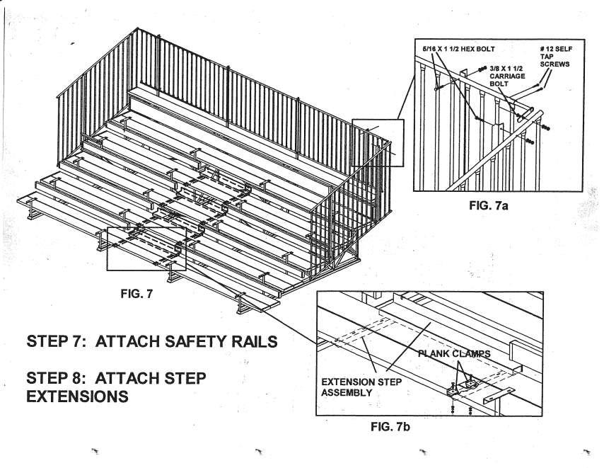
3 Temporarily, clamp or hold each support post in place. Mark each hole location in the seat riser using the support post as a templet. Remove the support post and drill a 3/8 hole at each bolt location. Next, attach the side rail support post as required. Adjust the post so it is it is true to the existing bleacher frames. Tighten all of the attachment hardware. STEP 5: PLACEMENT OF TOP SEAT AND SECOND TIER WALK PLANK(s) IMPORTANT: All seat planks are anodized aluminum. Walk planks and split planks are mill finished aluminum. Anodized planks are duller in apperance and have a cleaner finish. Mill finished aluminum is brighter in appearance. Note the difference and separate accordingly. Before proceeding, make sure the frames are properly spaced on 6 feet centers at the front of the bleacher frame assembly and are square to each other (Fig 5). Position the top seat plank so that it is centered between the the top two side safety rail supports. There should be approximately ½ gap at each end of the plank. Attach the plank to the top of each seat support bracket as indicated in Fig 5a. Make sure the plank clamp is saddled over the ribs on the bottom of the plank on both sides of each clamp. Do not tighten the plank clamps until all clamps on each plank are in place. Position the lowest walk plank(s) as shown in Fig. 5. The walk plank(s) should be offset from the vertical seat risers the same distance as the top seat plank. (DOUBLE WALK PLANKS) Use a 1 space between the rear walk plank and the seat support riser as indicated in Fig 5a. The gap between double walk planks should be 3/16 to ¼. Attach walk planks the same as seat planks. STEP 6: ATTACH WALK PLANKS AND SPLIT PLANKS All walk planks are full length. Depending on whether your bleacher is configured with a step aisle or not, split plank (kick boards) may or may not be full length. See Fig 6. Split planks are held in place by one plank clamp per seat riser. Adjust and position as shown in Fig. 6a. Note: (Fig. 6b) Split planks form the openings for the step aisle when steps are incorporated into the bleacher system. Make sure to use the same length split planks on each side of the bleacher so steps are properly configured in line from one tier to the next. STEP 7: ATTACH SAFETY RAILS Refer to Fig. 7a for attaching back and side safety rails. First attach the back safety rail to the back support post. Carefully lift and carry the safety rail assembly up the front of the bleacher. Center the safety railing with the top seat plank. Mark and drill 5/16 dia. holes in the top of the railing to match the spacing on the top of the support post. HINT: Hole spacing should be on 6 0 centers. Attach the railing at the top of each support post using the 5/16 bolts / hardware. Recheck the safety rail position and then drill and bolt the lower back safety rail into place. If using side safety rails, first insert the corner attachement bracket into the top tube of the back safety rail. Then positon the side safety rail in place and drill 5/16 holes through the top tube to bolt the top of the safety railing in place. Adjust the bottom of the side safety rail and drill and bolt it into place.
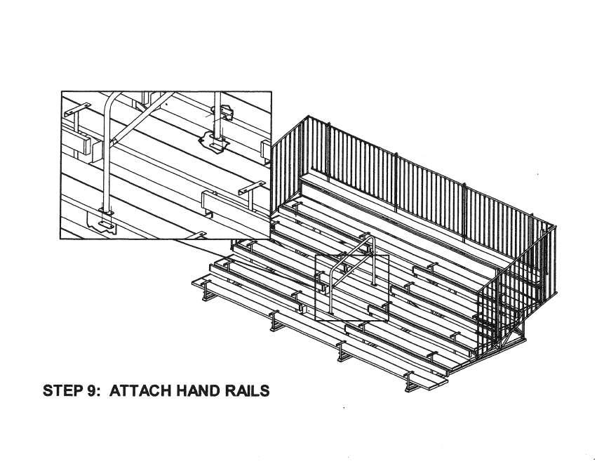
4 Next, position the corner attachment bracket into place against the side safety rail and and drill a 3/8 hole though the square hole and attach the bracket using a 3/8 carriage bolt. Adjust the bracket in or out of the top tube of the back safety rail and secure with two (2) # 12 self tapping screws. STEP 8: ATTACH STEP EXTENSIONS Step extensions are preassembled. Position each assembly on the back of each double walk plank tier and attach to the bottom of the walk planks using 8 each plank clamps as shown in Fig. 7b. Make sure not to leave more then ¼ spacing between plank and extension. STEP 9: HAND RAILS Hand rails can be added to aisle either before or after seat planks are installed. Hand rails are attached using the provided hardware ( 5/16 x 1 Grade 5 carraiage bolts, flat washer, washer and hex nut). Position each hand rail in the center of each step aisle (side to side from where the end of the seat planks will extend), so the post is up against the front walk plank on the next higher walk plank tier. Drill two 5/16 holes through each bolt down plate and fasten with the provided hardware. In all cases, the round head of the carraige bolt should be visible on top side of bleacher. Back up plates on the bottom of each leg are placed up inside the bottom side of the plank for added strength. A back up plate should also be used on the inside leading edge of the next step up. If using multiple hand rails on a single aisle, leave gaps between each hand rails to provide passage from one side of the aisle to the other side. In accordance with IBC recommendations, the gaps between these hand rails should be no less than 22 and no greater than 36.
5
6
7
8
9
10
11
12
π H-4408 ALUMINUM BLEACHERS 5-ROW x 15' PARTS uline.com TOOLS NEEDED
 π H-4408 1-800-295-5510 uline.com ALUMINUM BLEACHERS 5-ROW x 15' TOOLS NEEDED Square Tape Measure Rivet Gun 3/16" Drill Bit 1/2" Wrench Socket Wrench 1/2" Deep Well Socket #2 Phillips Bit Rubber Mallet
ASSEMBLY INSTRUCTIONS FOR T-10, T-11 & T-12 SERIES RACKS
 ASSEMBLY INSTRUCTIONS FOR T-10, T-11 & T-12 SERIES RACKS T12SHD-1 with 26 Legs shown above. Package Contents: HARDWARE KIT PARTS (8) 3/8-16 x 3 CARRAIGE BOLTS (1) RAIL DRIVER S SIDE ASSEMBLIES (20) 3/8-16
ASSEMBLY INSTRUCTIONS FOR HAULER II UNIVERSAL CAMPER SERIES RACKS
 ASSEMBLY INSTRUCTIONS FOR HAULER II UNIVERSAL CAMPER SERIES RACKS C11U2873-1 shown above Package Contents: HARDWARE KIT PARTS (4) 3/8-16 x 3 CARRAIGE BOLTS (1) RAIL DRIVER S SIDE ASSEMBLY (20) 3/8-16 x
GlideRite Retractable Cover System For Hot Spot Spas (SE & SLX only)
") List of Contents Quantity Description 12 #10 x 1 ½ Flat Head Phillips Screw (see pg. 2) 2 #10 x ½ Pan Head Phillips Screw (see pg. 2) 8 ¼ x 2 ½ Lag Bolt (see pg. 2) 7 ¼ 20 x 5 / 8 Hex Head Bolt (see pg.
List of Contents Quantity Description 12 #10 x 1 ½ Flat Head Phillips Screw (see pg. 2) 2 #10 x ½ Pan Head Phillips Screw (see pg. 2) 8 ¼ x 2 ½ Lag Bolt (see pg. 2) 7 ¼ 20 x 5 / 8 Hex Head Bolt (see pg.
Gared Pro-S Portable Backstop
 Models: 9616 & 9618 Installation, Operation and Maintenance Instructions Please read all instructions before attempting installation or operation of these units SAVE THESE INSTRUCTIONS FOR FUTURE USE PUBLICATION
Multi-Stage ASSEMBLY INSTRUCTIONS ST-8100 SERIES. 125 TAYLOR PARKWAY ARCHBOLD, OH PHONE: (419) FAX: (419)
 FAX: (419)") 125 TAYLOR PARKWAY ARCHBOLD, OH 43502 PHONE: (419) 445-8915 FAX: (419) 445-0367 www.biljax.com Multi-Stage ST-8100 SERIES ASSEMBLY INSTRUCTIONS ALL DRAWINGS ARE FOR ILLUSTRATION ONLY. PRINTED IN U.S.A.
125 TAYLOR PARKWAY ARCHBOLD, OH 43502 PHONE: (419) 445-8915 FAX: (419) 445-0367 www.biljax.com Multi-Stage ST-8100 SERIES ASSEMBLY INSTRUCTIONS ALL DRAWINGS ARE FOR ILLUSTRATION ONLY. PRINTED IN U.S.A.
ASSEMBLY INSTRUCTIONS FOR SERVICE BODY A MOUNT RACKS
 ASSEMBLY INSTRUCTIONS FOR SERVICE BODY A MOUNT RACKS T12 Service Body A shown with optional middle crossbar Package Contents: HARDWARE KIT PARTS (8) 3/8-16 x 3 CARRAIGE BOLTS (1) RAIL DRIVER S SIDE ASSEMBLIES
Installation Instructions - Model V4JSD 1
 Installation Instructions - Model V4JSD 1 Support Assemblies: Parts list: (Note see enclosed cut sheet for quantities and dimensional information) A vertical structural member (1 ½ x 1 ½ modular frame)
Assembly Instructions 10 X 10 Aluminum Roof Support
 Assembly Instructions 10 X 10 Aluminum Roof Support Aluminum Roof Support Bolt Package 16-5/16 X 2 ¼ SS Bolt 24-5/16 X 1 SS Bolt 40-5/16 SS Nylon Lock Nuts 16-5/16 SS Flat Washers 28-4 ½ Wood Screws 36-1
ASSEMBLY INSTRUCTIONS FOR HAULER II SERVICE BODY A RACK
 ASSEMBLY INSTRUCTIONS FOR HAULER II SERVICE BODY A RACK T12USBA-1 shown above Package Contents: HARDWARE KIT PARTS (4) 3/8-16 x 3 CARRAIGE BOLTS (1) RAIL DRIVER S SIDE ASSEMBLY (20) 3/8-16 x 2 CARRAIGE
INSTALLATION GUIDE N5-DS48-4
 INSTALLATION GUIDE N5-DS48-4 Shelving ( steel ) Transit High Roof & Medium Roof Promaster Standard Roof & High Roof Nissan NV High Roof Sprinter Low Roof & High Roof Box Truck / Trailer QUICK START GUIDE
SINCE 1922 P UBLICATION N O
 SINCE 1922 GARED SPORTS MICRO-Z SET-UP INSTRUCTIONS VERY IMPORTANT! READ INSTRUCTIONS CAREFULLY AND FOLLOW STEP BY STEP SET-UP PROCEDURE P UBLICATION N O. 5 5 1 7 5 2 9 1 6 Recommended tools and accessories.
GlideRite Retractable Cover System For HotSpring & Tiger River Spas (except Classic & pre-2000 Landmark Spas)
") List of Contents Quantity Description 12 #10 x 1 ½ Flat Head Phillips Screw (see pg. 2) 2 #10 x ½ Pan Head Phillips Screw (see pg. 2) 8 ¼ x 2 ½ Lag Bolt (see pg. 2) 7 ¼ 20 x 5 / 8 Hex Head Bolt (see pg.
List of Contents Quantity Description 12 #10 x 1 ½ Flat Head Phillips Screw (see pg. 2) 2 #10 x ½ Pan Head Phillips Screw (see pg. 2) 8 ¼ x 2 ½ Lag Bolt (see pg. 2) 7 ¼ 20 x 5 / 8 Hex Head Bolt (see pg.
INSTALLATION GUIDE NS Double Clamp Ladder Rack NV200 / City Express ( Aluminum )
") INSTALLATION GUIDE 1530-NS Double Clamp Ladder Rack NV200 / City Express ( Aluminum ) QUICK START GUIDE Phase 1 - Assembly q 1.1 Setup... q 1.2 Ladder Rack Assembly... 3-5 5-13 Phase 2 - Installation q
INSTALLATION GUIDE 1530-NS Double Clamp Ladder Rack NV200 / City Express ( Aluminum ) QUICK START GUIDE Phase 1 - Assembly q 1.1 Setup... q 1.2 Ladder Rack Assembly... 3-5 5-13 Phase 2 - Installation q
Austin Standing Seam Awning with Overhead Braces Assembly and Installation Instructions. Assembly Instructions
 Austin Standing Seam Awning with Overhead Braces Assembly and Installation Instructions Be sure to use safety glasses when assembling and installing the awning. Some metal parts may have sharp edges. Use
CONTENTS TOOL LIST U P S I D E I N N O V A T I O N S, L L C RAMP AND STEP SYSTEM ASSEMBLY INSTRUCTIONS. Revised: June 2013
 U P S I D E I N N O V A T I O N S, L L C RAMP AND STEP SYSTEM ASSEMBLY INSTRUCTIONS TOOL LIST Required Tools: - Reciprocating Saw with Metal Cutting Blade - Drill - 7/16 Drill Bit for Metal Drilling -
General Features. Low Profile. The SMART BOXX stands only 1.5 off of the bed of your truck so cargo space is maximized
 General Features Low Profile. The SMART BOXX stands only 1.5 off of the bed of your truck so cargo space is maximized Two Sizes Short Box :74 L X 47 W X 7 T and Long Box 92 L X 47 W X 7 T All Aluminium
TechBench Installation Manual
 Manual Table of Contents TechBench Overview....2 Bench Assembly Linear,36 (914,4mm) Wide 96 (2438,4mm) Wide 3,4,5,6,7 Bench Assembly Linear,24 (609,6mm) Wide 30 (762mm) Wide..8,9 Bench Assembly Corner
PLAYLAND 72 SPIRAL SLIDE 3.5 Posts, 3.5 Posts / 48 Grid and 5 Posts
 PLAYLAND 72 SPIRAL SLIDE 3.5 Posts, 3.5 Posts / 48 Grid and 5 Posts USER GROUP: 2-12 RECOMMENDED CREW: 2 people TOOLS REQUIRED: T-30 TORX tool (supplied by manufacturer) T-45 TORX tool (supplied by manufacturer)
Instruction Guide 4A90L
 Instruction Guide 4A90L Kargo Master Rancho Cordova, CA 95742 800-343-7486 CustomerService@KargoMaster.com DATE: *PLEASE READ ALL INSTRUCTIONS AND WARNINGS PRIOR TO ASSEMBLING, INSTALLING, AND USING THIS
EZ-Grow Professional Greenhouse Bench
 EZ-Grow Professional Greenhouse Bench Photo may be of a different but similar model. (Bench shown includes the expanded metal top; additional purchase is required for some models.) 2010 ClearSpan All Rights
Assembly Instructions 10 X 10 Aluminum Frame Building
 Assembly Instructions 10 X 10 Aluminum Frame Building 27 97 9 8 47 36 74 52 10 10 X 10 Square Building W/ Dome Includes: The Steel Entry Door with a Dead Bolt Lock assembly and Aluminum Door Frame. Metal
INSTALLATION INSTRUCTIONS FOR FRONT CASTING DECK RAIL Ranger
 INSTALLATION INSTRUCTIONS FOR FRONT CASTING DECK RAIL Ranger TOOLS REQUIRED FOR INSTALLATION: Drill motor, (1) 5/16 inch drill bit, (1) 13/64 drill bit, (1) 3/16 inch hex wrench (1) 3/32 inch hex wrench.
Sliding Door Kit
 YOU MUST READ THIS DOCUMENT BEFORE YOU BEGIN TO ASSEMBLE THE DOOR KIT. Thank you for purchasing this GrowSpan door kit. When properly assembled and maintained, this product will provide years of reliable
SwingSafe Swing-Away Mailbox Support Diagram
 SwingSafe Swing-Away Mailbox Support Diagram Wood Mounting Plates Top Arm (B) Muffler Clamps (A) Carriage Bolts and Nuts Bottom Arm 4-Foot U-Channel Post USPS Recommended 42-44 Height Ground Slope Hex
Showpiece Cabinet Integrated Stand For 32" - 52" LCD HDTV
 Showpiece Cabinet Integrated Stand For 32" - 52" LCD HDTV Installation and Assembly Instructions 2009 Incredible Technologies Inc. Version 0109 Showpiece Cabinet Integrated Stand for 32" - 52" LCD HDTV
PRORAC CONTRACTOR SERIES UNIVERSIAL STEEL TRUCK / CAP RACK INSTALLATION INSTRUCTIONS
 PRORAC CONTRACTOR SERIES UNIVERSIAL STEEL TRUCK / CAP RACK INSTALLATION INSTRUCTIONS 1000 Lb. Capacity Bed Mount 750 Lb. Capacity Cap Mount Package Contents: Parts Hardware (4) Legs (12) 3/8-16 x 1-1/4
Assembly Instructions
 10' and 12' Octagon Cedar Gazebo Assembly Instructions Toll Free: 866.768.8465 Hours: 9-5 Monday-Friday EST www.homeplacestructures.com Package ships as shown revised 06/20/09 Cedar Gazebo Assembly Instructions
MK52 Series ULTRA-LOW FREQUENCY VIBRATION ISOLATION WORKSTATION ASSEMBLY AND OPERATION INSTRUCTIONS
 MK52 Series ULTRA-LOW FREQUENCY VIBRATION ISOLATION WORKSTATION ASSEMBLY AND OPERATION INSTRUCTIONS i Information contained in this document is subject to change without notice and does not represent a
CTTR Tire Rack Required tools
 CTTR Tire Rack Required tools Torque wrench, ratchet, 9/16 socket, tape measure, and square edge. ASSEMBLY REQUIREMENTS *Torque all T-bolt nuts to 35-40 foot pounds. Failure to follow the assembly instructions
4099T Parts List. Front Bow Assy. (1) Rear Bow Assy. (1) Long Mounting Rail (2) Short Mounting Rail (2)
 Rear Bow Assy. (1) Long Mounting Rail (2) Short Mounting Rail (2)") 4099T Parts List Ver.2 Front Bow Assy. (1) Rear Bow Assy. (1) Small Mnt Foot (2) Large Mount Foot (2) Ladder Hook (2) Ladder Stop (2) Handle Extension (1) Long Mounting Rail (2) Short Mounting Rail (2)
4099T Parts List Ver.2 Front Bow Assy. (1) Rear Bow Assy. (1) Small Mnt Foot (2) Large Mount Foot (2) Ladder Hook (2) Ladder Stop (2) Handle Extension (1) Long Mounting Rail (2) Short Mounting Rail (2)
Austin Standing Seam Awning Assembly and Installation Instructions. Assembly Instructions
 Austin Standing Seam Awning Assembly and Installation Instructions Be sure to use safety glasses when assembling and installing the awning. Some metal parts may have sharp edges. Use work gloves to handle
Side Mount INSTRUCTION BOOKLET #C122 BED STYLE: PARK CITY
 Side Mount BED STYLE: PARK CITY INSTRUCTION BOOKLET #C1 WARNING! ALL MURPHY/WALLBED SYSTEMS CONTAIN STORED ENERGY. FAILURE TO USE AND FOLLOW THESE INSTRUCTIONS DURING THE INSTALLATION PROCESS COULD RESULT
Gared Pro Portable Backstop
 Models: 5016, 5017, & 5018 Installation, Operation and Maintenance Instructions Please read all instructions before attempting installation or operation of these units PUBLICATION NO. 551754436 SAVE THESE
Modular XP Ramp Assembly Manual
 Modular XP Manual 1 Contents Overview... 2-5 1.1 Tools required...6 1.2 Hardware list...6 Ramp & Platform Standard Parts 2.1 Ramp Parts...7 2.2 Platform Parts...8 2.3 Standard Platform Configurations...
WILDING WALLBEDS INSTALLATION INSTRUCTION Side Mount
 WILDING WALLBEDS INSTALLATION INSTRUCTION Side Mount For Wallbed models: Do-It-Yourself Insturction booklet C92 WARNING! ALL MURPHY/WALLBED SYSTEMS CONTAIN STORED ENERGY. FAILURE TO USE AND FOLLOW THESE
Video Wall Installation Instructions 2W X 3H, 3W X 3H
 Video Wall Installation Instructions 2W X 3H, 3W X 3H www.microndisplaysolutions.com Table of Contents Important Safety Instructions... 3 Configuration... 4 Package Contents, included and optional items...
40993 Parts List. Front Bow Assy.(1) Rear Bow Assy.(1)
 Rear Bow Assy.(1)") 40993 Parts List Front Bow Assy.(1) Rear Bow Assy.(1) Rail Mnt Foot(4) Ladder Hook (2) Ladder Stop (2) Mounting Clip-ProMaster Only (6) Mounting Bracket(6) Long Mounting Rail(2) Short Mounting Rail(2)
40993 Parts List Front Bow Assy.(1) Rear Bow Assy.(1) Rail Mnt Foot(4) Ladder Hook (2) Ladder Stop (2) Mounting Clip-ProMaster Only (6) Mounting Bracket(6) Long Mounting Rail(2) Short Mounting Rail(2)
Installing the CACS Ceiling with Aisle Ducts
 Installing the CACS Ceiling with Aisle Ducts Complete these instructions to install the Cold Aisle Containment System (CACS) Ceiling with Aisle Ducts. The CACS Ceiling and Aisle Ducts are designed to work
Installation Instructions
 Installation Instructions Follow these simple instructions to install your OneDayCab! IMPORTANT: Unpack and check shipment for damage. Verify color, size and parts before demolition. Installation of interiors
Locker Pedestal Installation Instructions
 Locker Pedestal Installation Instructions LK-PED-INST-0314r1 Parts List Single Pedestal Back to Back Pedestal Horizontal Support Tube TS-169 Post Flange TS-190 Post Cap Fasteners Provided: #8 x ¾ round
BISON GOOSENECK FOOTBALL 1 PAIR OF GOAL POSTS
 Instruction Manual BISON GOOSENECK FOOTBALL 1 PAIR OF GOAL POSTS Customer Service (800) 247-7668 P A R T S L I S T Item Qty Description Item Qty Description A 2 GOOSENECK POLE I 4 UPRIGHTS B 2 BAND CLAMP
Strata. urniture. Adriana Instructions. Parts in the Arm Box: Parts in the Body Box: Watch our assembly videos at
 1A Watch our assembly videos at www.strataf.com/videos Parts in the Arm Box: Arm - Outside View Arm - Inside View 1B Parts in the Body Box: Back Deck x 1 Seat Deck x 1 with the Feet attached Back Panel
2-PIECE STAIRWAY ASSEMBLY
 REVISED 2/12/15 2-PIECE STAIRWAY ASSEMBLY STEP 1: LAY OUT THE RIGHT AND LEFT SIDE TOP AND BOTTOM RISER PANELS AS SHOWN IN FIGURE 1. BOLT THE SPLICE PLATE (#15114C for OSHA F SERIES; #15412C for BOCA U
General Guidelines:
 ASSEMBLY INSTRUCTIONS Congratulations on your new Patriot Dock purchase. This manual contains instructions to assemble basic dock configurations for use at typical residential shoreline application. Please
Breathable Wall Light Traps & Blackout Fan & Shutter Kits
 Breathable Wall Light Traps & Blackout Fan & Shutter Kits 2017 Growers Supply All Rights Reserved. Reproduction is prohibited without permission. Maintain controlled airflow without sacrificing blackout
55000/55010 Installation Instructions
 A. Install 55015 B. Bolt roof rails, 55020/55025, to front hoop. C. Assemble 55026 D. To install without drilling into bumper. E. If mounting directly to bumper. A. 55015 Installation Instructions 55000/55010
INSTALLATION INSTRUCTIONS
 INSTALLATION INSTRUCTIONS For Wallbed models: Do-It-Yourself BOOKLET #C90 WARNING! ALL MURPY/WALLBED SYSTEMS CONTAIN STORED ENERGY. FAILURE TO USE AND FOLLOW THESE INSTRUCTIONS DURING THE INSTALLATION
POWER PEAK TM ASSEMBLY INSTRUCTIONS. step-by-step assembly and installation. Version 1, Rev D P/N
 POWER PEAK TM ASSEMBLY ISTRUCTIOS step-by-step assembly and installation Version 1, Rev D P/ 5803028 The Power Peak TM A few words about this product The Power Peak is designed to mount on standard I-Beams
Modular XP Ramp Assembly Manual
 Modular XP Manual 1 Contents Overview... 2-5 Section 1: 1.1 Tools required...6 1.2 Hardware list...6 Ramp & Platform Standard Parts 2.1 Ramp Parts...7 2.2 Platform Parts...8 2.3 Standard Platform Configurations...
MANUAL DE MONTAJE ASSEMBLY MANUAL AIREADOR DE PLUG AERATOR MODEL # AE-48T. Hardware & Parts Listing Assembly Instructions Maintenance Notes for
 ASSEMBLY MANUAL Hardware & Parts Listing Assembly Instructions Maintenance Notes for 48 PLUG AERATOR MANUAL DE MONTAJE Lista de piezas y tornillería Instrucciones de armado Notas de mantenimiento para
HONDA RIDGELINE (KIT #601) Installation Instructions (to be used in addition to owners manual)
 Installation Instructions (to be used in addition to owners manual)") HONDA RIDGELINE (KIT #601) Installation Instructions (to be used in addition to owners manual) IMPORTANT NOTE: Read before beginning installation. These instructions replace all of Step 1 of the instructions
HONDA RIDGELINE (KIT #601) Installation Instructions (to be used in addition to owners manual) IMPORTANT NOTE: Read before beginning installation. These instructions replace all of Step 1 of the instructions
Mighty Mo GX Series Cabinet Installation Guide. OR Rev /11
 Mighty Mo GX Series Cabinet Installation Guide OR-71601787 Safety and Warning ATTENTION The exclamation point within an equilateral triangle is intended to alert the user to the presence of important operating
Pickup Box Utility Rack Package Installation (Instruction ID: )
") 017 Chevrolet Colorado Pickup - WD (VIN S) Canyon, Colorado Accessory Installation Manual N America Document ID: 3966961 Pickup Box Utility Rack Package Installation (Instruction ID:3144879) Installation
017 Chevrolet Colorado Pickup - WD (VIN S) Canyon, Colorado Accessory Installation Manual N America Document ID: 3966961 Pickup Box Utility Rack Package Installation (Instruction ID:3144879) Installation
Qwik-Fence Installation Instructions
 Qwik-Fence Installation Instructions 1 Tools Required The following installation instructions should be used as a guide for installing Folding Guard Qwik-Fence Partitions. Good common sense and appropriate
Leveling Foot RB210. Leg Extender RLT66
 Landing for Right & Left Turn R342 ITEMS # 0254049, 0254061, 0254072, 0254076, 0016567, 0254099, 0254110, 0054116, 0254117, 0254126, 0254140, 0254150, 0254156 CUSTOM ACCESS RAMP SYSTEM MODELS # R100, R242,
Rockwell 4-in-1 Sliding Door
 Rockwell 4-in-1 Sliding Door ASSEMBLY INSTRUCTIONS ROCKWELL 4-IN-1 SLIDING DOOR Recommended Tools Drill with Phillips Bit Socket Wrench with 7/16 Socket Rubber Mallet Adjustable Square ROCKWELL 4-IN-1
 INSTRUCTION BOOKLET #C0 Watch step by step installation instructions at: https://www.wallbedsbywilding.com/wallbed-installation-studio-series/ WARNING! ALL MURPHY/WALLBED SYSTEMS CONTAIN STORED ENERGY.
FLOE DOCK FURNITURE WARNING ASSEMBLY INSTRUCTIONS
 FLOE DOCK FURNITURE ASSEMBLY INSTRUCTIONS KIT P/N 510-00400-02 KIT P/N 510-00405-02 KIT P/N 510-00406-02 KIT P/N 510-00410-02 WARNING IT IS THE INSTALLER S RESPONSIBILITY TO PROPERLY INSTALL this chair
Contractors Rack Assembly and Installation Instructions
 Part # 18601 & 16601 Contractors Rack Assembly and Installation Instructions 4751 Littlejohn St. Unit A, Baldwin Park, CA 91706 Page 1 of 12 11/13/08 Thank you for purchasing the Paramount Restyling Contractors
Grade 8 Enriched Math Catapult Project 2012 Step by Step Instructions to building a catapult
 Grade 8 Enriched Math Catapult Project 2012 Step by Step Instructions to building a catapult Grade 8 Enriched Math Project INSTRUCTION SHEET FOR CATAPULT Procedures, materials and tools: below is a step-bystep
Installation Instructions Kit, Base Rail Bracket Part # 31413
 Installation Instructions Kit, Base Rail Bracket Part # 31413 Dealer / Installer: Provide a copy of these Instructions to the end user of this product. These Instructions provide important operating and
INSTRUCTION BOOKLET #C20
 INSTRUCTION BOOKLET #C0 WARNING! ALL MURPHY/WALLBED SYSTEMS CONTAIN STORED ENERGY. FAILURE TO USE AND FOLLOW THESE INSTRUCTIONS DURING THE INSTALLATION PROCESS COULD RESULT IN SEVERE PERSONAL INJURY TO
INSTALLATION GUIDE 3020-FTH CONTOURED PARTITION
 INSTALLATION GUIDE 3020-FTH CONTOURED PARTITION Transit Partition ( Tempered Glass Window, Aluminum ) QUICK START GUIDE Phase 1 - Assembly q 1.1 Setup... q 1.1.1 Unpack components; compare with the bill
Modern Gatherings 60" TV Console Assembly Instructions
 Parts List Page 1 of 6 No. Description Sketch Quantity A Console 1 B Door 1 Thank you for purchasing this quality product. Be sure to check all packing material carefully for small parts that may have
Installing the Profile Privacy Panel. Assemble top mounting bracket. Prerequisites. Tools
 Installing the Profile Privacy Panel Complete these instructions to install the Profile Privacy Panel. Privacy panels are available in various heights to match tiers and include mounting hardware for slat
11 6 Round Building Assembly Instructions
 11 6 Round Building Assembly Instructions 11 6 Round Building Hardware List 1. Pro Rib Brite White 36 Wide X 68 Long (Siding Steel) 11 2. Top Wall Wheel Ring 3 3. Base Ring 3 4. 1 ½ X 68 Aluminum Tubes
ASSEMBLY OF THE KNOCKED-DOWN LADDERS: 8 to 12 STEPS STANDARD TOP AND SAFELOCK REQUIRED TOOLS
 ASSEMBLY OF THE KNOCKED-DOWN LADDERS: 8 to 12 STEPS STANDARD TOP AND SAFELOCK REQUIRED TOOLS SAFETY GLASSES 7/16" WRENCH OR SOCKET STEP LADDER OF APPROPRIATE HEIGHT (2) 9/16" WRENCHES OR SOCKETS RUBBER
Blackout Fan Kits with Breathable Wall Light Traps
 Blackout Fan Kits with Breathable Wall Light Traps 2018 Growers Supply All Rights Reserved. Reproduction is prohibited without permission. Maintain controlled airflow without sacrificing blackout environments.
Blackout Fan Kits with Breathable Wall Light Traps
 Blackout Fan Kits with Breathable Wall Light Traps 2018 Growers Supply All Rights Reserved. Reproduction is prohibited without permission. Maintain controlled airflow without sacrificing blackout environments.
Your order will be shipped with the supports and rail components packaged inside the ramp package. Each accessory package is labeled.
 instructions About Your Order. Your order will be shipped with the supports and rail components packaged inside the ramp package. Each accessory package is labeled. Check the Order Before the Carrier leaves!
INSTRUCTION BOOKLET #C21. For Wallbed models: KING SIZE
 For Wallbed models: KING SIZE INSTRUCTION BOOKLET #C1 WARNING! ALL MURPHY/WALLBED SYSTEMS CONTAIN STORED ENERGY. FAILURE TO USE AND FOLLOW THESE INSTRUCTIONS DURING THE INSTALLATION PROCESS COULD RESULT
M10 x 75mm Sockethead Cap Screws. 5mm Fender Washer (12) Included - (8) Required. #10 x 2.5" PH Wood Screws. (30) Included - (24) Required
 Included - (8) Required. #10 x 2.5 PH Wood Screws. (30) Included - (24) Required") Door System Unit - Hardware Tools Included: (2) 2mm Allen Wrenches, (2) 3mm Allen Wrenches, (2) 4mm Allen Wrenches, (2) 6mm Allen Wrenches, and (1) 8mm T-Handle Allen Wrench Tools Required: Phillips Screwdriver,
Door System Unit - Hardware Tools Included: (2) 2mm Allen Wrenches, (2) 3mm Allen Wrenches, (2) 4mm Allen Wrenches, (2) 6mm Allen Wrenches, and (1) 8mm T-Handle Allen Wrench Tools Required: Phillips Screwdriver,
HILGARD Part Number Spectrum Lane ~ Missoula MT ~
 HILGARD Part Number 20121 7100 Spectrum Lane ~ Missoula MT 59808 800.791.8056 ~ www.spectrumproducts.com 20121 Rev A You have purchased a Spectrum Products Hilgard Guard Chair. Providing the unit is installed
Elements Pole Mounting System
 Elements Pole Mounting System Installation Manual www.peavey.com Elements Pole Mounting System Installation Manual The Elements Pole Mounting System is a simple and straightforward pole mounting solution
Assembly Instructions
 Unite Panel System Hinge Door July 2016 #12 x / slotted hex washer head bolt Figure 1 threshold bracket frame Detail F threshold bracket threshold bracket (installed) #12 x / slotted hex washer head bolt
CHEVY SuperBracket Mounting Kit #0826
 CHEVY SuperBracket Mounting Kit #0826 #1200 SuperGlide (16K) #0800 SuperGlide (20.5K) Gross Trailer Weight (Maximum) Vertical Load Weight (Max. Pin Weight) 16,000 lbs. 4,000 lbs. Gross Trailer Weight (Maximum)
Assembly Instructions
 18' W x 10' H or 12' H Peak Style Frame Assembly Assembly Instructions Before you start: 2+ individuals recommended for assembly, approximate time 3 hours. Recommended tools: Power Drill, Safety Glasses,
6' Wide Premium Greenhouse Benches
 6' Wide Premium Greenhouse Benches Premium Greenhouse Bench with Stationary Top 2015 FarmTek All Rights Reserved. Reproduction is prohibited without permission. STK# DIMENSIONS 112416S6X08 6' W x 3' H
Warnings. Description. Prior to Installation Tools Needed
 Warnings Failure to act in accordance with the following may result in death or personal injury. The JT Strong Arm Stabilizer System is intended to eliminate chassis movement in travel trailers and fifth
ALUMINUM POLE VAULT STANDARDS SPECIFICATIONS
 SPECIFICATIONS Specifications: All aluminum construction for superior corrosion resistance. Dual height scales provide English and Metric measurements ranging from 7' to 8'. Wide stance base for improved
INSTRUCTION BOOKLET #34. For Wallbed models: KING SIZE SIERRA WITH STORAGE HEADBOARD
 For Wallbed models: KING SIZE SIERRA WITH STORAGE HEADBOARD INSTRUCTION BOOKLET #34 WARNING! ALL MURPHY/WALLBED SYSTEMS CONTAIN STORED ENERGY. FAILURE TO USE AND FOLLOW THESE INSTRUCTIONS DURING THE INSTALLATION
RBP-1215B-RX DODGE RAM QUAD CAB RX3
 RBP-1215B-RX3 2002-2017 DODGE RAM 15-3500 QUAD CAB RX3 Passenger side RX-3 Side Step Drill Template Passenger side rear Modular Bracket (6) L Support Brackets Driver side rear Modular Bracket Driver side
INSTALLATION GUIDE. C20-FTM STRAIGHT PARTITION Transit Partition ( Perforated Window, No Access, Steel )
") INSTALLATION GUIDE C20-FTM STRAIGHT PARTITION Transit Partition ( Perforated Window, No Access, Steel ) QUICK START GUIDE Phase 1 - Assembly q 1.1 Setup... q 1.1.1 Unpack components; compare with the bill
INSTALLATION GUIDE C20-FTM STRAIGHT PARTITION Transit Partition ( Perforated Window, No Access, Steel ) QUICK START GUIDE Phase 1 - Assembly q 1.1 Setup... q 1.1.1 Unpack components; compare with the bill
INSTALLATION MANUAL WEEKENDER STEEL LADDER RACK
 TRUCK STORAGE SOLUTIONS SECURING YOUR REPUTATION INSTALLATION MANUAL WEEKENDER STEEL LADDER RACK STEEL & ALUMINUM SIDE BOX WITH PACK RAT DRAWER UNITS MODELS ATTENTION: PLEASE READ AND UNDERSTAND ALL INSTRUCTIONS
INVENT3D Printer Kit Disassembly Instructions
 INVENT3D Printer Kit Disassembly Instructions Version 6 AST2 10/26/16 1 I. General Disassembly Instructions Use the case layer drawings to ensure that components are stored in the appropriate location
TOOLS REQUIRED FOR ASSEMBLY. Rubber Mallet or Plastic Tip Hammer PARTS REQUIRED FOR ASSEMBLY OF SINGLE ENTRY STARTER.
 TOOLS REQUIRED FOR ASSEMBLY Rubber Mallet or Plastic Tip Hammer Top Cover Support PARTS REQUIRED FOR ASSEMBLY OF SINGLE ENTRY STARTER Back Stop Divider Closed 'L' Upright Slotted Reinforcement Support
Roll In W/L Dock PAGE 1
 Roll In W/L Dock PAGE 1 1 2 3/8 X 1 CARRIAGE BOLT SS 3/8 FLANGE NUT BRASS 3 4 1/2-13 X 1.25 SQ BOLT SS 1/2 SQ NUT BRASS 5 3/8-16 X 2.5" BOLT SS PAGE 2 6 7 BRACE BRKT SINGLE AXLE TUBE 8 9 3" AXLE WASHER
SENC 150. Cross Feed Installation... Mounting Information... Center reading head... First Steps...
 Cross Feed Y Axis on Right Hand Side Cross Feed Installation... * Supplied with encoder hardware M4 x 8mm SHSS Mounting block 1/4-20 x 1/2 SHSS (2) per block *1/4-20 x 1 BHCS (2) or 1/4-20 x 1-1/4 BHCS
 For Wallbed models: KING SIZE INSTRUCTION BOOKLET #C1 Watch step by step installation instructions at: https://www.wallbedsbywilding.com/wallbed-installation-studio-series/ WARNING! ALL MURPHY/WALLBED
Real Life Ninja Complete Starter Pack (14ft. Warped Wall) Assembly Instructions
 Assembly Instructions") MATERIALS: 3 - Main Sections (Only 2 Sections for 10 ) 8 3 deck screws for joining sections inside of 2 Rock Wall Panels (with pre-installed t-nuts. Top panel comes with ladder mounting block preinstalled.)
MATERIALS: 3 - Main Sections (Only 2 Sections for 10 ) 8 3 deck screws for joining sections inside of 2 Rock Wall Panels (with pre-installed t-nuts. Top panel comes with ladder mounting block preinstalled.)
Required Tools: Suggested Additional Tools: 1 Cordless Drill with Robertson Bits 1 Ratchet Wrench 1 7/16 or 11mm socket 1 7/16 or 11mm Gear Wrench
 Thank you for your recent purchase of a Cabinets by Hayley garage cabinet system. You are about to experience the best made cabinets that you can purchase. Cabinets by Hayley are designed for beauty and
Next Level Security. This 2-tier locker ships flat to save on freight, comes in galvanized and powder coat finish options, and has a modular design.
 T WO - T I E R B IK E LO C K E R Next Level Security We take long-term bicycle storage to new heights with the new Dero Two-Tier Bike Locker. It is easy to load and provides a space-saving solution to
May 14, Installation Manual
 May 14, 2012 Installation Manual Contents MAG TRACKER Components...1 Mount Installation...7 Module Installation & Grounding...11 Maintenance...14 Warranty......14 Contact Information......14 May 14, 2012
Before Assembling the Storage Wall
 Chapter 1 Assembling the Lista Storage Wall Lista provides two types of standard Storage Walls: B251 and B255. The design, construction, assembly, and quality are identical for both types, however, B251
M2 Assembly. M2 Sub-Assemblies mm Belt Sub-Assembly mm Belt Sub-Assembly Spider Sub-Assembly... 4
 M2 Assembly Table of Contents M2 Sub-Assemblies... 3 630mm Belt Sub-Assembly... 3 702mm Belt Sub-Assembly... 3 Spider Sub-Assembly... 4 Idler Bolt Sub-Assembly... 8 Y Motor Sub-Assembly... 9 X Motor Sub-Assembly...
INSTALLATION INSTRUCTIONS
 INSTALLATION INSTRUCTIONS Furniture Solutions: 68 Shipstation with Storage Shelf Model Numbers: PB001 (D9001, D9010N, D9021, D9030, D9032/D9033, D9098, RC4054) Introduction This document provides the Pitney
CNC Router Parts PRO Machine Kit Cable Track Installation Instructions
 1 1 X CABLE TRACK TRAYS & BRACKETS The cable track on the side of the system is supported by a metal tray (or multiple trays for longer systems such as a PRO4896). These trays hang from brackets on the
 INSTRUCTION BOOKLET #C10 Watch step by step installation instructions at: https://www.wallbedsbywilding.com/wallbed-installation-studio-series/ WARNING! ALL MURPHY/WALLBED SYSTEMS CONTAIN STORED ENERGY.
ASSEMBLY INSTRUCTIONS FOR 2B3001 DELUXE EUROPEAN CLUB GOAL
 Most Kwik Goal products carry a Lifetime Guarantee. For details or claims, visit kwikgoal.com or contact customer service at 1-800-531-4252. ASSEMBLY INSTRUCTIONS FOR 2B3001 DELUXE EUROPEAN CLUB GOAL 1.