OWNER S MANUAL CT058 8 JOINTER
|
|
|
- Evelyn Anderson
- 5 years ago
- Views:
Transcription


1 OWNER S MANUAL CT058 8 JOINTER
2 Index General Safety Instructions Page 3 Specific Safety Instructions Page 4 CT058 Jointer Features Page 5 Illustrated Features Page 6 Unpacking Page 7 Assembly Assembling Jointer to Cabinet base Page 8 Installing Drive Belts Page 8 Installing Drive Belts, Continued Page 9 Cutter Head Guard Page 9 Knife Assembly Page 10 Replacing Knives Page 10 Adjusting the Fence Page 11 Adjusting Infeed Table Page 11 Adjusting Outfeed Table Page 12 Installing Magnetic Switch Page 13 Electrical Page 14 Operation Jointing Page 15 Planing Safely Page 16 Rabbeting Page 17 Honing Knives Page 18 Cutter Head Removal Page 19 Schematic & Parts Listing Schematic Body Page 20 Parts List Body Page 21 Schematic Base Page 22 Parts List Base Page 23 Warranty Information Page 24 2
3 GENERAL SAFETY INSTRUCTIONS EXTREME CAUTION SHOULD BE USED IN OPERATING ALL POWER TOOLS. KNOW YOUR POWER TOOL, BE FAMILIAR WITH ITS OPERATION. READ THE OWNER S MANUAL AND PRACTICE SAFE USAGE PROCEDURES AT ALL TIMES. CONNECT your machine ONLY to the matched and specified power source. WEAR SAFETY GLASSES, RESPIRATORS, HEARING PROTECTION and SAFETY SHOES when operating heavy machinery. Always wear safety glasses. DO NOT wear loose clothing or jewellery when operating machinery. A Safe Environment is important. Keep the area free of dust, dirt and other debris in the immediate vicinity of the machine. BE ALERT! Do Not Use prescription or other drugs that may affect your ability or judgement to safely use this machine. NEVER leave an operating tool unattended. NEVER reach over the table when the tool is in operation. ALWAYS keep blades, knives or bits sharp and properly aligned. ALWAYS keep all safety guards in place and ensure their proper function. ALWAYS use push sticks and featherboards to safely feed your work through the machine. ALWAYS make sure that any tools used for adjustments are removed before operating the machine. ALWAYS keep bystanders safely away while operating machinery. THINK SAFETY. WORK SAFELY. Never attempt a procedure if it does not feel safe or comfortable. 3
4 CT058 JOINTER SPECIFIC SAFETY INSTRUCTIONS Always keep the cutter head knives sharp and free of rust, tar and pitch Always use push blocks when jointing stock that does not provide a reasonable distance of safety for your hands. Never allow your hands to pass directly over the cutter head. Always make sure that the exposed cutter head behind the fence is guarded particularly when jointing near the leading edge such as in rabbetting. Never perform jointing operations on wood materials shorter than 8, narrower than 3/4" or less than 1/4" in thickness. Do not perform planing operations on wood material shorter than 4, narrower than 3/4", wider than 8 or thinner than 1/2". Maintain the proper relationship of the infeed and outfeed table surfaces and the cutter head knife path. Never back your workpiece into the spinning cutter head. Never make cuts deeper than 1/16 in a single pass to prevent overloading the machine and to prevent dangerous kickback. 4
5 Features As part of the growing line of Craftex woodworking equipment, we are proud to offer the CT058. The Craftex name guarantees Craft Excellence. By following the instructions and procedures laid out in this owner s manual, you will receive years of excellent service and satisfaction. The CT058 is a professional tool and like all power tools, proper care and safety procedures should be adhered to. Motor 1 1/2 HP, Single Phase, Ball Bearing Mounted. Dual Belt Drive. Magnetic Switch. Extra Long Bed, 65 x 9. Heavy-Duty, Cast-Iron, Precision Ground Tables Mounted on Inclined Dovetail Ways. Precise Gib Adjustments. Quick-Adjust Levers for infeed and outfeed tables. Positive Fence stops at 90 and 45 degrees. Totally Enclosed Cabinet with built-in chip chute. Three-knife Balanced Ball Bearing Cutter Head. Maximum Cutting Depth 1/2". Cutter Head Speed 5,000 RPM. Dual Belt Drive. Weight 220 kg. 2 Push Pads Included. 2 Year Warranty. 5
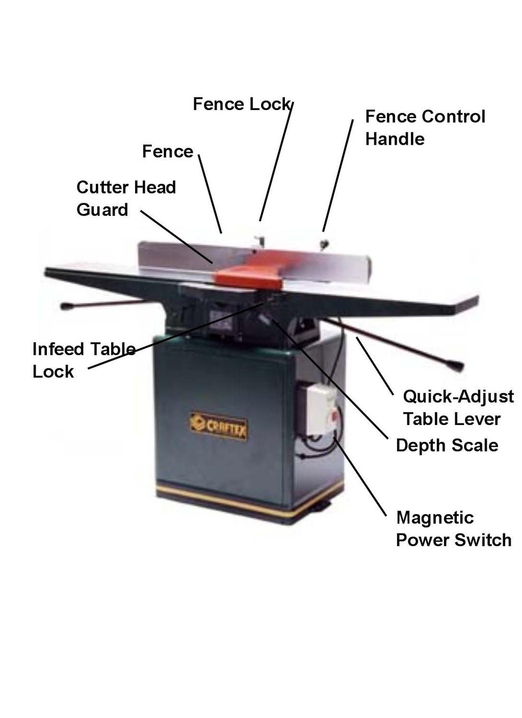
6 Illustrated Features 6


7 Unpacking The Craftex CT058, 8 Jointer is shipped in two cartons, one containing the sheet metal cabinet base and motor and the other containing the jointer and other small components. Carefully remove all of the packing material and recycle where available. Safety glasses and work gloves should be worn when un-packing as there may be sharp corners, nails or other sharp objects that could cause personal injury. Open all of the cartons or packages and remove the contents. Set the contents aside and see that the packages are empty before discarding them. The CT058 Jointer is shipped with a protective coating on the cast-iron parts to protect them from corrosion. This coating should be removed prior to assembly using a cloth and mineral spirits. Wipe all surfaces clean and dry them thoroughly. When the parts are dry, apply a generous coat of paste wax and buff dry. This will help prevent future corrosion. (Base Components) 7


8 Assembly Assembling the Jointer to the Cabinet Base Place the sheet metal Cabinet Base in close proximity to where you plan to finally place the CT058 Jointer. Place the Jointer on the Cabinet Base being sure that the cabinet top cutter head opening is on the same side as the motor pulley. CAUTION: The CT058 Jointer is heavy and should be lifted by more than one person or with a mechanical aid. There are 3 hex-head screws with lock washers in the parts package and these should be used to secure the Jointer to the Cabinet Base. These should be fastened from below and up through the cabinet. Installing/Adjusting the Drive Belts Remove the Upper Drive Belt Pulley Cover to gain access to the Drive Pulleys. Fit the two Drive belts on the Motor Drive Pulley and then feed the belts up through the Base Cabinet and over the Cutter Head drive Pulleys. 8

9 Assembly, Continued Installing/Adjusting Drive Belts, Continued Should the drive belts be too tight, loosen the adjustment screws on the motor-mount base Cutter Head Guard The shaft of the Cutter Head Guard fits into the socket on the side edge of the infeed table. Loosen the locking screw, insert the shaft and tighten the screw. 9

10 Assembly, Continued Replacing Knives Disconnect the CT058 Jointer from its power source. Loosen the 5 Allen knife setting screws starting with the centre one followed by the two end screws and the remaining ones. Carefully remove the knife and the locking bar being careful not to lose any of the five-knife pressure springs. Repeat this procedure for the remaining two knives. Reassemble the knives in reverse order but be certain to replace the knives with their sharp edges facing the infeed table. Do not tighten the Allen screws until you have placed the knife-setting gauge on the cutter head with the protrusion on the knife s edge. Tighten the Allen Screws in the reverse order to the above being certain that all are tight. 10


11 Assembly, Continued Adjusting the Fence With the fence in the 90-degree position, use a combination square to determine if the fence is square to the tables. Should this not be so, loosen the Fence Locking Levers and adjust the 90- degree Adjusting Screw. Tighten the Locking Levers. To adjust the fence in the 45- degree position, repeat the above steps but with the fence set in the 45-degree position. Use the 45- degree Adjusting Screw to make any corrections. Tighten the Locking Levers. Moving the fence angle or to move it forwards or backwards, use the Fence Handle. Adjusting the Infeed Table Adjusting the Infeed Table is a simple process. Simply loosen the Infeed Table Lock, grasp the Quick-Adjust Lever and raise or lower the Infeed Table to the desired position. There is a Depth Scale to indicate the depth of the cut. Caution: Never attempt to remove more than 1/16 of material in a single pass. 11

12 Assembly, Continued Adjusting the Outfeed Table For accurate results from your Craftex CT058 Jointer, the Outfeed Table must be perfectly level with the Cutter Head Knives at their highest point. The knives must be parallel to the table and project equally from the Cutter Head. To achieve this, loosen the Outfeed Table Lock and remove the Upper Pulley Cover on the rear of the Jointer. Using a straight edge, lay it across the Outfeed Table where the Cutter Head opening is located. Rotate the Cutter Head slowly by hand by turning the Upper Drive Belt Pulley. The knife-edges must just touch the straight edge. If one knife appears to high, it must be re-set. Loosen the five lock screws on the cutter head for that particular knife. Start with the centre screw, followed by the end screws and then the remaining two. Set your straight edge on the centre of the knife, snug that screw, move the straight edge to the back and repeat. Bring the straight edge to the front and repeat. When it is determined that the knife is parallel on its full length, secure the set screws. If all of the knives appear to be too high or low, loosen the Outfeed Table Lock and raise or lower the table with the Quick-Adjust Outfeed Table Lever and adjust accordingly. Tighten the Outfeed Table Lock securely. 12

13 Assembly, Continued Installing the Magnetic Power Switch The Magnetic Power Switch carton contains the wiring Schematic for the motor supplied with the CT058 Jointer. Feed the wires to the motor through the hole provided in the lower side of the Cabinet Base. Mount the Magnetic Power Switch on the lower side of the Cabinet Base as indicated. 13
14 Electrical A qualified electrician should be employed to make the electrical connections for the CT058 Jointer. Make sure that the electrical characteristics match the motor nameplate and the power source. Also make sure that the jointer is used on a properly fused circuit and that the correct wire size is employed. 14


15 Operation Jointing For the best results from your CT058 Jointer it is important to feed your workpiece with the grain of the wood. Proper adjustment of both the Infeed and the Outfeed Tables will provide the best results. If the Outfeed Table is too high the finished surface will be curved. If the Outfeed Table is too low, the finished surface will be gouged. Correctly setting the Tables will result in perfect jointing. 15


16 Operation, Continued Planing Safely For edge planing, hold the workpiece as illustrated being sure to keep your fingers well above the table surface. Should the workpiece be too small to safely use your hands, use push pads or push sticks as illustrated. 16


17 Operation, Continued Rabbeting To make a rabbet on a workpiece, bring the fence forward to the required distance from the outer edge of the infeed table and the required distance from the edge of the cutter head. Lower the infeed table for the first pass. Remove the knife guard. Do Not attempt to make a full rabbet in one pass, several small passes will result in better work. Replace the blade guard when your rabbeting work is complete. 17

 may be removed by moving one of the knives slightly to the left or right.")
18 Operation, Honing Honing Knives The Craftex CT058 Jointer must be maintained on a regular basis and one of these maintenance operations is keeping the planer knives sharp. Dull, dirty or nicked knives will produce poor jointing results. The knives should be routinely checked. If the knives are simply dull, you can restore the edge by honing the knives in place. Knives can be honed a number of times before they must be removed for re-grinding. Should a small nick appear in the knife edges, the effect of this (a small ridge on the workpiece) may be removed by moving one of the knives slightly to the left or right. Honing is best achieved with the Busy Bee B1659 Jointer Knife Honing Tool. A simple and effective tool. Disconnect the power supply Remove the fence or slide it back fully to expose all of the knifeedges. Remove the blade guard. Clean the knife and cutter head with mineral spirits to remove pitch, gum and tar. Wipe the parts dry. Wedge a small piece of wood between the cutter head and the frame to keep the cutter head from moving while you are honing the knives. Place a couple of drops of honing oil on the honing stone and draw it across the full length of the knife being certain the stone makes full contact with the blade. Start the process with the coarse stone and finish with the finer stone. Remove any traces of honing oil when completed. Replace the cutter head guard and then make a few test cuts. 18
19 Operation, Continued Cutter Head Removal When it is necessary to remove the cutter head assembly for maintenance, the following procedures should be followed. Disconnect the CT058 from the power source. Remove the fence. Remove the drive belts. Set both the infeed and outfeed tables to their lowermost positions, being sure to loosen the butterfly lock screws first. Remove the two bearing cap screws. From the drive belt end, carefully slide the cutter head assembly out. Reverse the above procedures to reinstall the assembly. 19


20 Schematic - Body 20


21 21
22 Schematic - Base 22


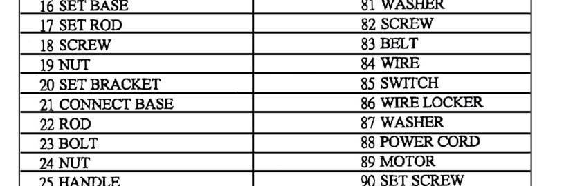
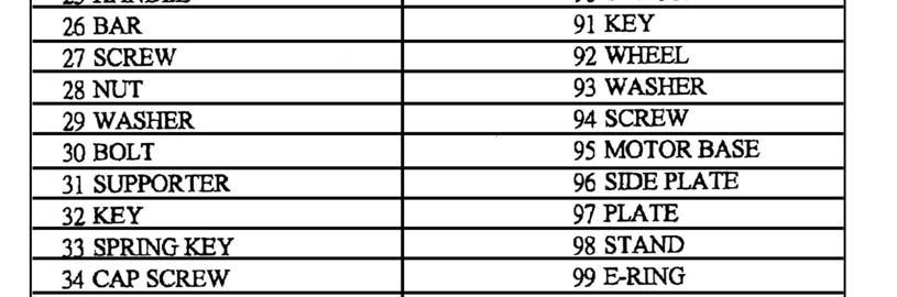
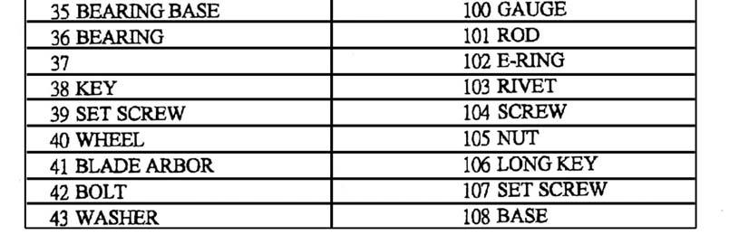
23 Parts List - Base 23
24 CRAFTEX 2 YEAR LIMITED WARRANTY Craftex warrants every product to be free from defects in materials and agrees to correct such defects where applicable. This warranty covers two years for parts and 90 days for labour (unless specified otherwise), to the original purchaser from the date of purchase but does not apply to malfunctions arising directly or indirectly from misuse, abuse, improper installation or assembly, negligence, accidents, repairs or alterations or lack of maintenance. Proof of purchase is necessary. All warranty claims are subject to inspection of such products or part thereof and Craftex reserves the right to inspect any returned item before a refund or replacement may be issued. This warranty shall not apply to consumable products such as blades, bits, belts, cutters, chisels, punches etceteras. Craftex shall in no event be liable for injuries, accidental or otherwise, death to persons or damage to property or for incidental contingent, special or consequential damages arising from the use of our products. RETURNS, REPAIRS AND REPLACEMENTS To return, repair, or replace a Craftex product, you must visit the appropriate Busy Bee Tools showroom. Craftex is a brand of equipment that is exclusive to Busy Bee Tools. For replacement parts directly from Busy Bee Tools, for this machine, please call BUSY(2879), and have your credit card and part number handy. All returned merchandise will be subject to a minimum charge of 15% for re-stocking and handling with the following qualifications. Returns must be pre-authorized by us in writing. We do not accept collect shipments. Items returned for warranty purposes must be insured and shipped pre-paid to the nearest warehouse (see locations on inside back cover of this manual). Returns must be accompanied with a copy of your original invoice as proof of purchase. Returns must be in an un-used condition and shipped in their original packaging a letter explaining your reason for the return. Incurred shipping and handling charges are not refundable. Busy Bee will repair or replace the item at our discretion and subject to our inspection. Repaired or replaced items will be returned to you pre-paid by our choice of carriers. Busy Bee reserves the right to refuse reimbursement or repairs or replacement if a third party without our prior authorization has carried out repairs to the item. Repairs made by Busy Bee are warranted for 30 days on parts and labour. Any unforeseen repair charges will be reported to you for acceptance prior to making the repairs. The Busy Bee Parts & Service Departments are fully equipped to do repairs on all products purchased from us with the exception of some products that require the return to their authorized repair depots. A Busy Bee representative will provide you with the necessary information to have this done. For faster service it is advisable to contact the nearest Busy Bee location for parts availability prior to bringing your product in for repairs. 24
25 25
26 26
27 27
CT Box and Pan Brake User Manual
 CT153 12 Box and Pan Brake User Manual Important Safety Precautions Plead read all the instructions before using this tool. 1) Always keep your work area clean. Cluttered areas invite injuries. 2) Do not
CX HEAVY DUTY BENCHTOP GRINDER User Manual
 CX900 10 HEAVY DUTY BENCHTOP GRINDER User Manual TABLE OF CONTENTS General Safety Instructions for Machines... 3 Specific Safety Instructions... 4 CX900 Features... 5 Physical Features... 6 Proper Grounding...
CX301 5-HP HEAVY DUTY SHAPER with DIGITAL READOUT User Manual
 CX301 5-HP HEAVY DUTY SHAPER with DIGITAL READOUT User Manual TABLE OF CONTENTS General Safety Instructions...3 Specific Safety Instructions...4 CX301Features...5 Physical Features...6 Set Up...7 Un-Packing...7
CX303 1-HP WOOD SHAPER USER MANUAL
 CX303 1-HP WOOD SHAPER USER MANUAL TABLE OF CONTENTS General Safety Instructions...3 Specific Safety Instructions...4 CX303 Features...5 Physical Features...6 Un-Packing...7 Set Up...7 Proper Grounding...8
MODEL T " SPIRAL CUTTERHEAD INSTRUCTIONS
 MODEL T10125 6" SPIRAL CUTTERHEAD INSTRUCTIONS The Model T10125 spiral cutterhead is designed to replace the straight knife cutterhead on the Model G0452 6" jointer. The total procedure of changing the
OPERATORS MANUAL. JOINTER by INVICTA. Model DI-42. (877) East (800) West
 East (800) West") OPERATORS MANUAL JOINTER by INVICTA Model DI-42 INVICTA USA (877) 308-6423 - East (800) 499-4682 - West English Version Model DI-42 General Instructions As with all equipment, safety is to be a priority.
OPERATORS MANUAL JOINTER by INVICTA Model DI-42 INVICTA USA (877) 308-6423 - East (800) 499-4682 - West English Version Model DI-42 General Instructions As with all equipment, safety is to be a priority.
MODEL T27697 & T " & 8" HELICAL CUTTERHEADS INSTALLATION INSTRUCTIONS
 MODEL T27697 & T27699 6" & 8" HELICAL CUTTERHEADS INSTALLATION INSTRUCTIONS For questions or help with this product contact Tech Support at (570) 546-9663 or techsupport@grizzly.com These indexable insert
Inventory (Figure 2)
") MODEL T10130/T10126 6" & 8" SPIRAL CUTTERHEAD INSTRUCTIONS The Model T10126/T10130 indexable insert spiral cutterheads are designed to replace straightknife cutterheads from the Grizzly jointer Models
MODEL T10130/T10126 6" & 8" SPIRAL CUTTERHEAD INSTRUCTIONS The Model T10126/T10130 indexable insert spiral cutterheads are designed to replace straightknife cutterheads from the Grizzly jointer Models
MODEL NO.: MI OPERATING MANUAL
 MODEL NO.: MI-81200 OPERATING MANUAL RULES for SAFE OPERATION Before you operate this machine, take a moment to read this manual. Learn how to use this jointer safely, and understand this machine s applications,
MODEL T " HELICAL CUTTERHEAD INSTALLATION INSTRUCTIONS
 MODEL T27696 12" HELICAL CUTTERHEAD INSTALLATION INSTRUCTIONS For questions or help with this product contact Tech Support at (570) 546-9663 or techsupport@grizzly.com Introduction The Model T27696 indexable
MODEL T " SPIRAL CUTTERHEAD INSTALLATION INSTRUCTIONS
 MODEL T27449 8" SPIRAL CUTTERHEAD INSTALLATION INSTRUCTIONS The Model T27449 indexable insert spiral cutterhead is designed to replace the straightknife cutterhead on the Grizzly jointer Model G0490W/G0490XW
Inventory (Figure 2)
") MODEL T10127 12" SPIRAL CUTTERHEAD INSTRUCTIONS The Model T10127 indexable insert spiral cutterhead is designed to replace the straightknife cutterhead from the Grizzly jointer Model G0609. The total procedure
MODEL T10127 12" SPIRAL CUTTERHEAD INSTRUCTIONS The Model T10127 indexable insert spiral cutterhead is designed to replace the straightknife cutterhead from the Grizzly jointer Model G0609. The total procedure
MODEL H " BYRD SHELIX CUTTERHEAD INSTRUCTIONS
 MODEL H9291 12" BYRD SHELIX CUTTERHEAD INSTRUCTIONS The Model H9291 12" Byrd Shelix cutterhead is designed to replace the straight-knife cutterhead on the Grizzly jointer Model G0609. The total procedure
INSTRUCTION MANUAL 6 & 8 JOINTERS WITH SPIRAL CUTTERHEAD. MODEL: KC-75FX (6 Jointer) MODEL: KC-85FX (8 Jointer)
 MODEL: KC-85FX (8 Jointer)") 6 & 8 JOINTERS WITH SPIRAL CUTTERHEAD MODEL: KC-75FX (6 Jointer) MODEL: KC-85FX (8 Jointer) INSTRUCTION MANUAL COPYRIGHT 2007 ALL RIGHTS RESERVED BY KING CANADA TOOLS INC. WARRANTY INFORMATION 2-YEAR LIMITED
6 & 8 JOINTERS WITH SPIRAL CUTTERHEAD MODEL: KC-75FX (6 Jointer) MODEL: KC-85FX (8 Jointer) INSTRUCTION MANUAL COPYRIGHT 2007 ALL RIGHTS RESERVED BY KING CANADA TOOLS INC. WARRANTY INFORMATION 2-YEAR LIMITED
Assembly Instructions and Parts Manual JPSF-1 Fence and JPSR Rail Set
 Assembly Instructions and Parts Manual JPSF-1 Fence and JPSR Rail Set WALTER MEIER (Manufacturing) Inc. 427 New Sanford Road LaVergne, Tennessee 37086 Part No. M-708482 Ph.: 800-274-6848 Revision C2 02/2013
3-1/4 HP VARIABLE SPEED PLUNGE ROUTER
 IMPORTANT INFORMATION 2-YEAR LIMITED WARRANTY FOR THIS PLUNGE ROUTER KING CANADA TOOLS OFFERS A 2-YEAR LIMITED WARANTY FOR NON-COMMERCIAL USE. 3-1/4 HP VARIABLE SPEED PLUNGE ROUTER PROOF OF PURCHASE Please
planer/thicknesser 200 x 120mm
 instructions for planer/thicknesser 200 x 120mm model no: sm1311 Thank you for purchasing a Sealey product. Manufactured to a high standard, this product will, if used according to these instructions,
Mortising Attachment
 Mortising Attachment Owner s Manual WARNING: Read carefully and understand all ASSEMBLY AND OPERATION INSTRUCTIONS before operating. Failure to follow the safety rules and other basic safety precautions
Assembly Instructions and Parts Manual JPSF-1 Fence and JPSR Rail Set #
 Assembly Instructions and Parts Manual JPSF-1 Fence and JPSR Rail Set #1002493 JET 427 New Sanford Road LaVergne, Tennessee 37086 Part No. M-708482 Ph.: 800-274-6848 Revision C3 02/2014 www.jettools.com
Record the serial number and date of purchase on your parts list for future reference.
 Jointer Model: 0-0 Parts List Record the serial number and date of purchase on your parts list for future reference. Serial number: Date of purchase: Part # 0-0PL For more information: www.rikontools.com
Model Assembly & Operating Instructions
 30 SHEAR BRAKE ROLL Model 05907 Assembly & Operating Instructions Diagrams within this manual may not be drawn proportionally. Due to continuing improvements, actual product may differ slightly from the
9 QUICK RELEASE WOODWORKING VISE
 9 QUICK RELEASE WOODWORKING VISE 94386 OPERATING INSTRUCTIONS Due to continuing improvements, actual product may differ slightly from the product described herein. 349 Mission Oaks Blvd., Camarillo, CA
MODEL SETUP & OPERATION MANUAL DOVETAIL JIG FEATURES SPECIFICATIONS
 SETUP & OPERATION MANUAL FEATURES Male and female dovetail joints are cut simultaneously, to ensure perfectly matched dovetail joints. Side stops provided, allow repeated precise dovetail joint cutting
HOLE CUTTER SHARPENER ASSEMBLY & SERVICE MANUAL
 HOLE CUTTER SHARPENER ASSEMBLY & SERVICE MANUAL WARNING You must thoroughly read and understand this manual before operating the equipment, paying particular attention to the Warning & Safety instructions.
OWNER S MANUAL - ShopStrop
 OWNER S MANUAL - ShopStrop Precision Sharpening System Part Number SS-S (28289) CAUTION: Before using your ShopStrop Precision Sharpening System, read this manual and follow all its Safety and Operating
SECTION 9: PARTS Fence & Cutterhead
 (G0855 Only) (G0856 Only) SECTION 9: PARTS Fence & Cutterhead 1 2 3 4 65 6 5 23 111 111 7 27 130 131 132 133 136 134 135 117 12 40 8 9 13 10 9 14 15 8 11 18 25 29 63 19 20 21 17 22 28 26 26 24 40-3 40-2
ALL RIGHTS RESERVED BY KING CANADA TOOLS INC.
 INDUSTRIAL RIP FENCE SYSTEM MODELS KRF-10/30L12-30 CONTRACTOR SAWS KRF-10/52L12-52 CONTRACTOR SAWS KRF-100/T50L12-50 CABINET SAWS INSTRUCTION MANUAL COPYRIGHT C 2000 ALL RIGHTS RESERVED BY KING CANADA
BUY PARTS ONLINE AT GRIZZLY.COM!
 SECTION 9: PARTS Tables, Fence & Cutterhead 28 29 26 27 25 23 23 22 24 22 35 37 36 38 16 15 17 18 39 11 14 19 20 21 13 12 6 7 8 9 10 1 2 5 49 3 4 3 31 30 6 7 94 93 95 40 96 43 42 44 45 46 47 48 55 55-4
Assembly Instructions and Parts Manual 5C Collet Closer for GHW Lathes Model CC-GHW
 Assembly Instructions and Parts Manual 5C Collet Closer for GHW Lathes Model CC-GHW JET 427 New Sanford Road LaVergne, Tennessee 37086 Part No. M-321519 Ph.: 800-274-6848 Revision G1 03/2014 www.jettools.com
Power Planer 1900B/N1900B/1902
 Power Planer 1900B N1900B 1902 SPECIFICATIONS Model 1900B/N1900B/1902 Planing width... 82 mm Planing depth... 1 mm Shiplapping depth... 9 mm No load speed (min -1 )...16,000 Overall length... 290 mm Net
INSTRUCTION MANUAL TAPER ATTACHMENT MODEL M1022. Phone: (360) On-Line Technical Support: FOR USE WITH MODEL M1019
 On-Line Technical Support: FOR USE WITH MODEL M1019") MODEL M1022 TAPER ATTACHMENT FOR USE WITH MODEL M1019 INSTRUCTION MANUAL Phone: (360) 734-3482 On-Line Technical Support: tech-support@shopfox.biz #6809BL COPYRIGHT DECEMBER, 2004 BY WOODSTOCK INTERNATIONAL,
MODEL M1022 TAPER ATTACHMENT FOR USE WITH MODEL M1019 INSTRUCTION MANUAL Phone: (360) 734-3482 On-Line Technical Support: tech-support@shopfox.biz #6809BL COPYRIGHT DECEMBER, 2004 BY WOODSTOCK INTERNATIONAL,
SawStop. Contractor Fence Assembly OWNER S MANUAL. Model CNS-SFA
 Contractor Fence Assembly OWNER S MANUAL Model CNS-SFA Warranty warrants to the original retail purchaser of the Contractor Fence Assembly accompanying this manual that the fence assembly will be free
Model D4500/D4501 6" & 8" Indexable Insert Spiral Cutterheads Instruction Sheet
 Model D4500/D4501 6" & 8" Indexable Insert Spiral Cutterheads Instruction Sheet Phone #: (360) 734-3482 Online Tech Support: tech-support@shopfox.biz Web: www.shopfox.biz Introduction These indexable-insert
Jointer. Given a properly adjusted jointer, instruction and demonstration of use, each student will be able to:
 Jointer I. Competencies Given a properly adjusted jointer, instruction and demonstration of use, each student will be able to: A. Identify the major parts of the jointer. B. Complete a written test on
VARIABLE SPEED WOOD LATHE. Model DB900 INSTRUCTION MANUAL
 VARIABLE SPEED WOOD LATHE Model DB900 INSTRUCTION MANUAL 1007 TABLE OF CONTENTS SECTION...PAGE Technical data.. 1 General safety rules....1-3 Specific safety rules for wood lathe.....3 Electrical information.4
VARIABLE SPEED WOOD LATHE
 MODEL MC1100B VARIABLE SPEED WOOD LATHE INSTRUCTION MANUAL Please read and fully understand the instructions in this manual before operation. Keep this manual safe for future reference. Version: 2015.02.02
MODEL M1023 QUICK CHANGE COLLET ATTACHMENT INSTRUCTION MANUAL. Phone: On-Line Technical Support:
 MODEL M1023 QUICK CHANGE COLLET ATTACHMENT INSTRUCTION MANUAL Phone: 1-360-734-3482 On-Line Technical Support: tech-support@shopfox.biz #6727BL COPYRIGHT JANUARY, 2005 BY WOODSTOCK INTERNATIONAL, INC.
MODEL T " HELICAL CUTTERHEAD INSTALLATION INSTRUCTIONS
 MODEL T27698 6" HELICAL CUTTERHEAD INSTALLATION INSTRUCTIONS For questions or help with this product contact Tech Support at (570) 546-9663 or techsupport@grizzly.com The Model T27698 indexable insert
Guild of Oregon Woodworkers Shop Safety Test
 Guild of Oregon Woodworkers Shop Safety Test You must pass the Test with an 80% or better and self-correct it to 100% Make sure you put the answers under the correct portion of the answer sheet for the
Agricultural Mechanics and Technology Power Tool Safety Rules
 Agricultural Mechanics and Technology Power Tool Safety Rules Name: BAND SAW Use: Cutting curves, circles and irregular shapes. 1. Use clean SHARP blades. 2. The teeth should always point DOWN. 3. Adjust
Assembly Instructions and Parts Manual 5C Collet Closer for ZX Series Lathes Model CC-ZX
 Assembly Instructions and Parts Manual 5C Collet Closer for ZX Series Lathes Model CC-ZX JET 427 New Sanford Road LaVergne, Tennessee 37086 Part No. M-321292 Ph.: 800-274-6848 Revision B 03/2014 www.jettools.com
EllisSaw.com. EllisSaw.com P.O. Box Verona, WI
 P.O. Box 9019 Verona, WI 9-019 GENERAL OPERATING & SAFETY INSTRUCTIONS * READ INSTRUCTIONS BEFORE USE * CAUTION: Disconnect power supply cord from power source when doing repair work or changing belt.
Inventory (Figure 2)
") MODEL T24631 8" SPIRAL CUTTERHEAD Installation INSTRUCTIONS For questions or help with this product contact Tech Support at (570) 546-9663 or techsupport@grizzly.com Introduction The Model T24631 spiral
MODEL T24631 8" SPIRAL CUTTERHEAD Installation INSTRUCTIONS For questions or help with this product contact Tech Support at (570) 546-9663 or techsupport@grizzly.com Introduction The Model T24631 spiral
INSTRUCTION BOOKLET AND WARRANTY INFORMATION 6 BENCH GRINDER
 INSTRUCTION BOOKLET AND WARRANTY INFORMATION 6 BENCH GRINDER Part No.: SW1250 PLEASE READ CARE AND SAFETY INSTRUCTIONS BEFORE USE SPECIFICATIONS Part No.: SW1250 Input Voltage: 240V Frequency: 50Hz Rated
GENERAL OPERATIONAL PRECAUTIONS
 GENERAL OPERATIONAL PRECAUTIONS WARNING! When using electric tools, basic safety precautions should always be followed to reduce the risk of fire, electric shock and personal injury, including the following.
10 x 6 Planer/Thicknesser
 01550 10 x 6 Planer/Thicknesser Please read and fully understand the instructions in this manual before operation. Keep this manual safe for future reference. 1 Specifications 2 Safety Rules.3-4 Unpacking.5
x 43 Wood Lathe
 Please dispose of packaging for the product in a responsible manner. It is suitable for recycling. Help to protect the environment, take the packaging to the local amenity tip and place into the appropriate
Shrinker and stretcher
 Shrinker and stretcher Model 96465 Assembly And Operation Instructions Due to continuing improvements, actual product may differ slightly from the product described herein 3491 Mission Oaks Blvd, Camarillo,
12mm (Max) 6mm (Max) 82mm (Max) 12mm (Max) 6mm (Max)
 6mm (Max) 82mm (Max) 12mm (Max) 6mm (Max)") 1 1 2 2 3 3 82mm (Max) 12mm (Max) 12mm (Max) 6mm (Max) 4 4 5 6 8 6mm (Max) 0.5 0mm 1 5 6 7 7 8 9 9 A = B 10 11 12 D B 1 13 14 15 0 C A D E 16 17 18 F G D B N H J G I K 19 A 20 G L 21 C K 1mm L M 1mm 22
1 1 2 2 3 3 82mm (Max) 12mm (Max) 12mm (Max) 6mm (Max) 4 4 5 6 8 6mm (Max) 0.5 0mm 1 5 6 7 7 8 9 9 A = B 10 11 12 D B 1 13 14 15 0 C A D E 16 17 18 F G D B N H J G I K 19 A 20 G L 21 C K 1mm L M 1mm 22
CX ULTIMATE BAND SAW User Manual
 CX100 14 ULTIMATE BAND SAW User Manual Table of Contents General Safety Instructions------------------------------------------------------------------- 3 Specific Safety Instructions-------------------------------------------------------------------
OPERATOR'S MANUAL RULES FOR SAFE OPERATION
 OPERATOR'S MANUAL #4950300 ROUTER AND JIG SAW MOUNTING KIT (FOR USE WITH THE BT3000 TABLE SAW) CONGRATULATIONS AND THANK YOU FOR BUYING THIS RYOBI ROUTER AND JIG SAW MOUNTING KIT. Your new #4950300 Router
MODEL H7655/H " & 20" INDEXABLE INSERT SPIRAL CUTTERHEADS
 MODEL H7655/H7656 15" & 20" INDEXABLE INSERT SPIRAL CUTTERHEADS INSTRUCTION SHEET These indexable insert spiral cutterheads are designed to replace both straight-knife and spiral-knife cutterheads from
Quick Set Dovetail Jig
 Quick Set Dovetail Jig FOR HELP OR ADVISE ON THIS PRODUCT PLEASE CALL OUR CUSTOMER SERVICE HELP LINE : 01509 500359 THE MANUFACTURER RESERVES THE RIGHT TO ALTER THE DESIGN OR SPECIFICATION TO THIS PRODUCT
MODEL SETUP & OPERATION MANUAL DOVETAIL JIG FEATURES
 SETUP & OPERATION MANUAL FEATURES New clamping system for greater accuracy. Lockable template height for a stable platform for the router. Cuts precision matching dovetails with the same accuracy found
13 INDUSTRIAL PLANER
 13 INDUSTRIAL PLANER Model 39860 ASSEMBLY and Operating Instructions Visit our website at: http://www.harborfreight.com Read this material before using this product. Failure to do so can result in serious
x 36 Wood Lathe
 Please dispose of packaging for the product in a responsible manner. It is suitable for recycling. Help to protect the environment, take the packaging to the local amenity tip and place into the appropriate
15 Dovetail Jig. Instruction Manual. Part # 3452
 15 Dovetail Jig Instruction Manual Part # 3452 CAUTION: Please read, understand, and follow all manufacturers instructions, guidelines and owners manuals that come with your power tools. Peachtree Woodworking
Extendable Large Dovetail Jig
 Extendable Large Dovetail Jig Instruction Manual Part # 3458 CAUTION: Please read, understand, and follow all manufacturers instructions, guidelines and owners manuals that come with your power tools.
MODEL T28000 HEAVY-DUTY MOBILE BASE INSTRUCTIONS
 MODEL T28000 HEAVY-DUTY MOBILE BASE INSTRUCTIONS For questions or help with this product contact Tech Support at (570) 546-9663 or techsupport@grizzly.com Introduction Your new Model T28000 Heavy-Duty
Models 2230 and 2240
 Models 2230 and 2240 Overview... 2 Tools Needed... 2 Hardware...3 Assembly... 4-13 Installation... 14 Drawer Removal... 15 Operation... 15 Maintenance... 15 Accessories... 16 Limited Warranty... 16 Perform
UNIVERSAL STAND. Owner s Manual. Visit us on the web at QUESTION Model No. UT1002
 Owner s Manual Model No. UT1002 UNIVERSAL STAND QUESTION... 1 877 393 7121 Visit us on the web at www.southerntechllc.com You will need this manual for safety instructions, operating procedures, and warranty.
Circular Saw MODEL MT581. WARNING: For your personal safety, READ and UNDERSTAND before using. SAVE THESE INSTRUCTIONS FOR FUTURE REFERENCE.
 ENGLISH Circular Saw MODEL MT58 005337 DOUBLE INSULATION I N S T R U C T I O N M A N U A L WARNING: For your personal safety, READ and UNDERSTAND before using. SAVE THESE INSTRUCTIONS FOR FUTURE REFERENCE.
accidents which arise due to nonobservance and the safety information herein. SPECIFICATIONS
 7 TON ELECTRIC LOG SPLITTER Model: 05620 CALIFORNIA PROPOSITION 65 WARNING: You can create dust when you cut, sand, drill or grind materials such as wood, paint, metal, concrete, cement, or other masonry.
PEXTO NO. 137 & NO. 152 FOOT SQUARING SHEAR INSTRUCTIONS AND PARTS IDENTIFICATION
 PEXTO NO. 137 & NO. 152 FOOT SQUARING SHEAR INSTRUCTIONS AND PARTS IDENTIFICATION INSTRUCTIONS FOR ADJUSTING PEXTO FOOT SHEARS -- BEFORE OPERATING -- Remove Shears From Skids and Log in Place 1. This shear
 Surface planer or buzzer. Performs the tasks of dressing, squaring and straightening timber Machining short lengths of timber. Without the bridge guard. Without the appropriate training. Without PPE. Set
Owner s Manual & Safety Instructions
 Owner s Manual & Safety Instructions Save This Manual Keep this manual for the safety warnings and precautions, assembly, operating, inspection, maintenance and cleaning procedures. Write the product s
Jointer Quick Start Guide
 Jointer Quick Start Guide This jointer runs on 220V (208V really because, 3 phase power). Don t joint anything that might have metal in it, like nails or screws. Any metal that hits the blades ruins them.
INSTRUCTION MANUAL. Lathe Duplicator MODEL North Glenn Road, Casper, Wyoming woodworker.com
 140-069LatheDuplictr(1/12) 10/30/06 8:20 AM Page 1 INSTRUCTION MANUAL Lathe Duplicator MODEL 140-069 1108 North Glenn Road, Casper, Wyoming 82601 1-800-645-9292 woodworker.com 140-069LatheDuplictr(1/12)
OPERATOR'S MANUAL ROUTER MOUNTING KIT
 OPERATOR'S MANUAL MOUNTING KIT 4950301 (FOR USE WITH BT3000 AND BT3100 TABLE SAWS) Your new router mounting kit has been engineered and manufactured to Ryobi's high standard for dependability, ease of
MANUAL METAL SHRINKER/STRETCHER
 MANUAL METAL SHRINKER/STRETCHER Model 95062 ASSEMBLY AND OPERATING INSTRUCTIONS Due to continuing improvements, actual product may differ slightly from the product described herein. 3491 Mission Oaks Blvd.,
Specifications. Important Safety Information
 Specifications Tire Rim Capacity 4 to 12 Rim Height 16 (2) Bead Breaker Handles 21 Long Includes Aluminum Centering Cone (2) Nylon Spacers Important Safety Information 1. Do not exceed max. tire capacity.
Assembly Instructions and Parts Manual Taper Attachment for Bench Lathes Model TAK-13GH/BD
 Assembly Instructions and Parts Manual Taper Attachment for Bench Lathes Model TAK-13GH/BD JET 427 New Sanford Road LaVergne, Tennessee 37086 Part No. M-321442 Ph.: 800-274-6848 Revision B 03/2014 www.jettools.com
SawStop. T-GlideTM. Fence System- Professional Series II OWNER S MANUAL
 SawStop T-GlideTM Fence System- Professional Series II OWNER S MANUAL Warranty SawStop warrants to the original retail purchaser of a new T-Glide Fence System - Professional Series II from an authorized
OPERATOR S MANUAL Model 58B Prefeed / Dereeler
 110 Fairgrounds Drive P.O. Box 188 Manlius, NY 13104-0188 USA 315.682.9176 FAX: 315.682.9160 OPERATOR S MANUAL Model 58B Prefeed / Dereeler PRODUCTION WIRE PROCESSING EQUIPMENT Website: www.carpentermfg.com
9 PIECE TUNGSTEN CARBIDE HOLE SAW KIT. Model 90721
 9 PIECE TUNGSTEN CARBIDE HOLE SAW KIT Model 90721 Set up And Operating Instructions Diagrams within this manual may not be drawn proportionally. Due to continuing improvements, actual product may differ
30 Bending Brake. Model Assembly and Operating Instructions. Distributed exclusively by Harbor Freight Tools.
 30 Bending Brake Model 41311 Assembly and Operating Instructions Distributed exclusively by Harbor Freight Tools. 3491 Mission Oaks Blvd., Camarillo, CA 93011 Copyright 1999 by Harbor Freight Tools. All
6 BLADE CUTTER MODEL # PCC-6 OPERATION MANUAL
 4511 WAYNE AVENUE PHILADELPHIA PA 19144 TEL: 888-800-2663 FAX: 800-582-9643 6 BLADE CUTTER MODEL # PCC-6 OPERATION MANUAL CONTENTS I. INTRODUCTION TO BOND PCC-6 / MACHINE SPECIFICATIONS II. SAFETY PRECAUTIONS
Owner s Manual ODYSSEY BENCH MODEL. O4100B shown REV E. Southern Avenue, Phoenix, AZ USA Workhorseproducts.
 Owner s Manual ODYSSEY BENCH MODEL O4100B shown 67-1375 REV 218 3730 E. Southern Avenue, Phoenix, AZ 85040 USA 800-778-8779 Workhorseproducts.com 1 Table of Contents I. Introduction & Safety Information.
OWNER S MANUAL CONTENTS. The only table saw fence with Automatic Positioning Control TM
 The only table saw fence with Automatic Positioning Control TM OWNER S MANUAL Please read this owner s manual before use and keep it at hand for reference. Note: The INCRA TS II system consists of three
Owner s Manual & Safety Instructions
 Owner s Manual & Safety Instructions Save This Manual Keep this manual for the safety warnings and precautions, assembly, operating, inspection, maintenance and cleaning procedures. Write the product s
INSTALLATION & OPERATING INSTRUCTIONS. REDCO LETTUCE KING I and LETTUCE KING IV
 INSTALLATION & OPERATING INSTRUCTIONS for REDCO LETTUCE KING I and LETTUCE KING IV Lettuce King I Shown with optional Drum Ring Lettuce King IV TO BE SERVICED ONLY BY AUTHORIZED PERSONS P/N: 2802381 REV:
Sander. Finishing INSTRUCTION MANUAL. MODEL BO4550 MODEL BO45502 Without dust bag and punch plate DOUBLE INSULATION SPEC IF1 CAT1 ONS.
 Finishing INSTRUCTION MANUAL Sander MODEL BO4550 MODEL BO4550 Without dust bag and punch plate DOUBLE INSULATION SPEC IF CAT ONS Pad size No load speed lopml Dimensions (L x W x H) Net weight mmxloomm
Operating Instructions and Parts Manual 6-inch Woodworking Jointer Models JJ-6CSX, JJ-6CSDX, JJ-6HHDX
 Operating Instructions and Parts Manual 6-inch Woodworking Jointer Models JJ-6CSX, JJ-6CSDX, JJ-6HHDX WALTER MEIER (Manufacturing) Inc. 427 New Sanford Road LaVergne, Tennesseee 37086 Part No. M-708457DX
User Manual. Where Imagination Meets Innovation. FRESH AERO Easy Seat Tool For Grumman AA1 & AA5 Series Aircraft
 FRESH AERO Easy Seat Tool For Grumman AA1 & AA5 Series Aircraft Alpha Model For Grumman AA-1 & AA-5 Series Aircraft with Access Holes in Front Seat Buckets User Manual The Steelebrook Group Where Imagination
ITEM Pipe Thread Kit (10 Piece Set - 7 Dies) Assembly and Operating Instructions
 Assembly and Operating Instructions") ITEM 94098 Pipe Thread Kit (10 Piece Set - 7 Dies) Assembly and Operating Instructions 3491 Mission Oaks Blvd., Camarillo, CA 93011 Copyright 2006 by Harbor Freight Tools. All rights reserved. No portion
ITEM 94098 Pipe Thread Kit (10 Piece Set - 7 Dies) Assembly and Operating Instructions 3491 Mission Oaks Blvd., Camarillo, CA 93011 Copyright 2006 by Harbor Freight Tools. All rights reserved. No portion
GENERAL OPERATIONAL PRECAUTIONS PRECAUTIONS ON USING DISC GRINDER
 GENERAL OPERATIONAL PRECAUTIONS WARNING! When using electric tools, basic safety precautions should always be followed to reduce the risk of fire, electric shock and personal injury, including the following.
TUCANA-02 P PORTABLE END MILLING MACHINE USER S MANUAL
 TUCANA-02 P PORTABLE END MILLING MACHINE USER S MANUAL 1 CONTENTS Page 1. General Information 3 1.1. Introduction 3 1.2. Manufacturer 3 2. Machine s Description and Purpose of Use 3 2.1. Machine s description
ET-110 EXTREMA MACHINERY COMPANY, INC. P.O. BOX 1450, ALBANY, LOUISIANA (877) FAX (225)
 FAX (225)") ET-0 EXTREMA MACHINERY COMPANY, INC. P.O. BOX 450, ALBANY, LOUISIANA 707 (877) 398-7362 FAX (225) 567-2966 PREFACE The XT-0 is precision built and manufactured to satisfy the highest standards. For maximum
ET-0 EXTREMA MACHINERY COMPANY, INC. P.O. BOX 450, ALBANY, LOUISIANA 707 (877) 398-7362 FAX (225) 567-2966 PREFACE The XT-0 is precision built and manufactured to satisfy the highest standards. For maximum
Dowelling Jig. Instruction Manual
 FAI DOWJIG2 Dowelling Jig Instruction Manual Before using this product, read this manual entirely and follow all safety rules and operating instructions. Keep this manual for future reference. 5 Year Warranty
Model 72D Twin Blade Rotary Wire Stripper
 110 Fairgrounds Drive P.O. Box 188 Manlius, NY 13104-0188 USA 315.682.9176 FAX: 315.682.9160 OPERATOR S MANUAL Model 72D Twin Blade Rotary Wire Stripper PRODUCTION WIRE PROCESSING EQUIPMENT Website: www.carpentermfg.com
18 GAUGE ELECTRIC METAL SHEAR
 241-9895 18 GAUGE ELECTRIC METAL SHEAR Operator s Manual SAVE THIS MANUAL You will need this manual for safety instructions, operating procedures and warranty. Put it and the original sales receipt in
SHRINKER/STRETCHER SET Create radius bends and contours in sheet metal
 Owner s Manual & Safety Instructions Save This Manual Keep this manual for the safety warnings and precautions, assembly, operating, inspection, maintenance and cleaning procedures. Write the product s
Models 2130 and 2140
 Models 2130 and 2140 Overview... 2 Tools Needed... 2 Hardware... 2 Assembly... 3-10 Installation...11 Operation... 11 Maintenance... 12 Accessories...12 Limited Warranty... 12 Perform the following sequence
Sunset Swings By Health in Motion, LLC
 Sunset Swings By Health in Motion, LLC Model 421 Lounge Swing Assembly and Operation Manual Record Serial Number Here www.sunsetswings.com by Health In Motion, LLC. 11/6/2009 421 Owners Assembly and Operation
D R I L L - G R I N D E R S BL 13D-2
 D R I L L - G R I N D E R S BL 13D-2 2 Table of contents 1. General safety rules for all machines 3 2. Additional safety rules 4 3. Features 4 4. Specification 4 5. Operation 4 5.1 Assemble the fixture
PARTS. Base Cabinet & Motor PARTS. Model W1745W (For Machines Mfd. Since 9/16) V2 22V2-3 22V2-4 22V2-1 22V2-2
 V2 22V2-3 22V2-4 22V2-1 22V2-2") Model W1745W (For Machines Mfd. Since 9/16) Base Cabinet & Motor 22V2-1 22V2-2 22V2-5 22V2-9 22V2-8 22V2-7 22V2-6 22V2-3 22V2-4 22V2 23 24 26 25 46 47 48 49 44 45 15 14 16 17 50 18 13 12 11 7 20 9 8 9
Model W1745W (For Machines Mfd. Since 9/16) Base Cabinet & Motor 22V2-1 22V2-2 22V2-5 22V2-9 22V2-8 22V2-7 22V2-6 22V2-3 22V2-4 22V2 23 24 26 25 46 47 48 49 44 45 15 14 16 17 50 18 13 12 11 7 20 9 8 9
Models 2030 and 2040
 Models 2030 and 2040 Overview... 2 Tools Needed... 2 Hardware... 2 Assembly... 3-8 Installation... 9 Operation... 9 Maintenance... 10 Accessories... 10 Limited Warranty... 10 Document # 101290 0607 Printed
MODEL 7000 BEVEL-MILL
 MODEL 7000 BEVEL-MILL HECK INDUSTRIES P.O. BOX 425 HARTLAND, MI 48353 TOLL FREE: 800-886-5418 PHONE: 810-632-5400 FAX: 810-632-6640 WWW.HECKIND.NET INSTRUCTION MANUAL Save This Manual You will need the
SAVE THIS MANUAL FOR FUTURE REFERENCE. WARNING: To reduce the risk of. Part No. SP6442
 -3 23(5$725 60$18$/ PP-2,17(5 3/$1(5 WARNING: To reduce the risk of injury, the user must read and understand the operator s manual before using this product. Part No. SP6442 SAVE THIS MANUAL FOR FUTURE
20 TON HyDRAULIC SHOP PRESS with GRID GUARD 06/2015 INSTRUCTION MANUAL MODEL: KHP-20T-GG COPYRIGHT 2015 ALL RIGHTS RESERVED BY KING CANADA TOOLS INC.
 06/2015 20 TON HyDRAULIC SHOP PRESS with GRID GUARD MODEL: KHP-20T-GG INSTRUCTION MANUAL COPYRIGHT 2015 ALL RIGHTS RESERVED BY KING CANADA TOOLS INC. warranty INFORMATION 2-yEAR LIMITED WARRANTY FOR THIS