European Technical Assessment. ETA-12/0373 of Member of. General part
|
|
|
- Anissa McBride
- 5 years ago
- Views:
Transcription

1 INSTITU Schenkenstrasse 4 T Vienna Ι Austria F Ι mail@oib.or.at Designated according to Article 29 of Regulation (EU) No 305/2011 Member of European Technical Assessment General part ETA-12/0373 of Technical Assessment Body issuing the European Technical Assessment Österreichisches Institut für Bautechnik (OIB) Austrian Institute of Construction Engineering Trade name of the construction product Product family to which the construction product belongs Screws for use in timber constructions Manufacturer Schmid Schrauben Hainfeld GmbH Landstal Hainfeld Austria Manufacturing plants Schmid Schrauben Hainfeld GmbH Landstal Hainfeld Austria This European Technical Assessment contains 47 pages including 10 Annexes, which form an integral part of this assessment. This European Technical Assessment is issued in accordance with Regulation (EU) No 305/2011, on the basis of European Assessment Document EAD Screws for use in timber constructions. This European Technical Assessment replaces European technical approval ETA-12/0373 with validity from to
2 Page 2, Remarks Translations of the European Technical Assessment in other languages shall fully correspond to the original issued document and should be identified as such. Communication of this European Technical Assessment, including transmission by electronic means, shall be in full. However, partial reproduction may be made with the written consent of Österreichisches Institut für Bautechnik. Any partial reproduction has to be identified as such. Specific parts 1 Technical description of the product This European Technical Assessment 1 (ETA) applies to the screws for use in timber constructions. are self-tapping screws divided into a drill tip, optionally a compressor and/or cutting groove, thread, optionally a friction part, shank, and head of the screw. The screws are made from special carbon or stainless steel. The screws from special carbon steel are hardened. They are anti-friction coated and are electrogalvanized and passivated (yellow or blue), provided with a zinc-nickel coating or hotdip galvanised. The washers are made from carbon steel. Possible outer thread diameters as well as overall lengths for the are given in Table 1. The screws and washers correspond to the specifications given from Annex 0 to Annex 6. The material characteristics, dimensions and tolerances of the product not indicated in these Annexes, are given in the technical file 2 of the European Technical Assessment. Table 1: Possible outer thread diameter and overall length of screws Type of Schmid screws Outer thread diameter Overall length min. max. min. max. mm mm mm mm RAPID STARDRIVE SP Specification of the intended use(s) in accordance with the applicable European Assessment Document 2.1 Intended use The screws are used for connections in load bearing timber structures between wood-based members or between those members and steel members: - Solid timber of softwood of strength class C14 or better and solid timber of hardwood of strength class D18 or better according to EN and EN , - Glued laminated timber and glued solid timber of softwood of strength class GL20 or better according to EN or glued laminated timber of hardwood according to European Technical Assessments or national provisions that apply on the installation site, - Laminated veneer lumber LVL according to EN 14374, 1 The ETA-12/0373 was firstly issued in 2012 as European technical approval with validity from and amended and converted in 2017 to the European Technical Assessment. 2 The technical file of the European Technical Assessment is deposited at Österreichisches Institut für Bautechnik. 3 Reference documents are listed in Annex 10.
3 Page 3, - Cross laminated timber according to European Technical Assessments or national provisions that apply on the installation site. The screws may be used for connecting the following wood-based panels to the timber members mentioned above: - Laminated veneer lumber LVL according to EN 14374, - Solid wood panels according to EN and EN 13986, - Plywood according to EN 636 and EN 13986, - Oriented strand boards, OSB, according to EN 300 and EN 13986, - Particleboards according to EN 312 and EN 13986, - Fibreboards according to EN 622-2, EN and EN 13986, - Cement-bonded particle boards according EN and EN or European Technical Assessments or national provisions that apply on the installation site. Compression and tension reinforcement perpendicular to the grain with fully threaded screws as well as shear reinforcement with fully threaded screws with a diameter d 8 mm is allowed. In addition, screws with 6 mm d 12 mm may be used for fixing of thermal insulation on rafters and walls. The product shall be subjected to static and quasi static actions only. The product is intended to be used in service classes 1, 2 and 3 according to EN The scope of the screws regarding resistance to corrosion shall be defined according to national provisions that apply at the installation site considering environmental conditions. Hot-dip galvanised screws with a minimum thickness of the zinc coating of 55 μm as well as screws made of stainless steel may be used in conditions defined by service class 3. The field of application of the screws made of stainless steel shall be defined according to EN or national provisions that apply at the installation site. 2.2 General assumptions The screws for use in timber constructions are manufactured in accordance with the provisions of the European Technical Assessment using the manufacturing process as identified in the inspection of the manufacturing plant by Österreichisches Institut für Bautechnik and laid down in the technical file. The manufacturer shall ensure that the requirements in accordance with the Clauses 1, 2 and 3 as well as with the Annexes of the European Technical Assessment are made known to those who are concerned with design and execution of the works. Design The European Technical Assessment only applies to the manufacture and use of the screws for use in timber constructions. Verification of stability of the works including application of loads on the products is not subject to the European Technical Assessment. The following conditions shall be observed: Design of Schmid screws RAPID, STARDRIVE or SP is carried under the responsibility of an engineer experienced in such products. Design of the works shall account for the protection of Schmid screws RAPID, STARDRIVE and SP to maintain service classes 1 and 2 according to EN or national provisions that apply on the installation site. Schmid screws RAPID, STARDRIVE or SP are installed correctly.
4 Page 4, Design of the screws for use in timber constructions may be according to EN , taking into account of Annex 6 to Annex 9 of the European Technical Assessment. Hereby, the outer thread diameter d is used as nominal diameter d or rather effective diameter d ef and l ef is the threaded part in the timber member including point. Standards and regulations in force at the place of use shall be considered. Packaging, transport, storage, maintenance, replacement and repair Concerning product packaging, transport, storage, maintenance, replacement and repair it is the responsibility of the manufacturer to undertake the appropriate measures and to advise his clients on the transport, storage, maintenance, replacement and repair of the product as he considers necessary. Installation It is assumed that the product will be installed according to the manufacturer s instructions or (in absence of such instructions) according to the usual practice of the building professionals. The screws are either driven into the wood-based member without pre-drilling or in predrilled holes with a diameter not exceeding the inner thread diameter. The screw holes in steel members shall be pre-drilled with an adequate diameter greater than the outer thread diameter. Screws made of carbon steel with an outer thread diameter 5 mm d 12 mm may be driven into laminated veneer lumber LVL of beech or related products of hardwood with predrilling; screws with an outer thread diameter d = 8 mm (see Table A6.9) may be driven into laminated veneer lumber LVL of beech or related products of hardwood without predrilling. At least four screws shall be used in a connection with screws inserted in the timber member with an angle between screw axis and grain direction of less than 15. The penetration length of the threaded part of the screw shall be at least 20 d. To ensure a proper installation for screws with lengths of more than 800 mm a guiding hole of 5 d is recommended. For mounting of steel plates and wood-based panels the screw head must be placed on top of these members. The structural members which are connected with Schmid screws RAPID, STARDRIVE or SP shall - be in accordance with Clause 2.1; - ensure minimum spacing and edge distances in accordance with EN and Annex Working life/durability The provisions made in the European Technical Assessment (ETA) are based on an assumed intended working life of of 50 years, when installed in the works, provided that the screws are subject to appropriate installation, use and maintenance (see Clause 2.2). These provisions are based upon the current state of the art and the available knowledge and experience 4. The indications given as to the working life of the construction product cannot be interpreted as a guarantee neither given by the product manufacturer or his representative nor by EOTA nor by the Technical Assessment Body, but are regarded only as a means for choosing the appropriate products in relation to the expected economically reasonable working life of the works. 4 The real working life of a product incorporated in a specific works depends on the environmental conditions to which that works is subject, as well as on the particular conditions of the design, execution, use and maintenance of that works. Therefore, it cannot be excluded that in certain cases the real working life of the product can also be shorter than the assumed working life.
5 Page 5, 3 Performance of the product and reference to the methods used for its assessment 3.1 Essential characteristics of the product Table 2: Essential characteristics of the product and product performance Essential characteristic Product performance Basic requirement for construction works 1: Mechanical resistance and stability 1) 1 Dimensions Annex 0 to Annex 5 2 Characteristic yield moment Annex 6 3 Bending angle Annex 6 4 Characteristic withdrawal parameter Annex 6 5 Characteristic head pull-trough parameter Annex 6 6 Characteristic tensile strength Annex 6 7 Characteristic yield strength Annex 6 8 Characteristic torsional strength Annex 6 9 Insertion moment Annex 6 10 Spacing, end and edge distances of the screws and Annex 7, if relevant minimum thickness of the wood based material 11 Slip modulus for mainly axially loaded screws Annex 6 12 Durability against corrosion Basic requirement for construction works 2: Safety in case of fire 13 Reaction to fire Basic requirement for construction works 4: Safety and accessibility in use 14 Same as BWR 1 1) These characteristics also relate to basic requirement 4 for construction works Durability against corrosion The product is intended to be used in service classes 1, 2 and 3 according to EN The screws and washers made from carbon steel are electrogalvanized and yellow or blue passivated, coated with a zinc-nickel coating or hot-dip galvanised. The minimum thickness of the zinc coating of the screws is 5 μm and the minimum thickness of the zinc-nickel coating is 4 μm. The minimum thickness of the zinc coating of hot-dip galvanised screws is 55 μm. Steel no or or equivalent according to EN is used for screws made from stainless steel. Durability of is in accordance with EN or national provisions that apply on the installation site Reaction to fire are made from steel classified as Euroclass A1 in accordance with Commission Decision 96/603/EC, as amended by Commission Decision 2000/605/EC.
6 Page 6, 3.2 Assessment methods General The assessment of the essential characteristics in Clause 3.1 of the screws for use in timber constructions for the intended use, and in relation to the requirements for mechanical resistance and stability, for safety in case of fire and for safety and accessibility in use in use in the sense of the basic requirements for construction works 1, 2 and 4 of Regulation (EU) 305/2011 has been made in accordance with the European Assessment Document EAD , Screws for use in timber constructions Identification The European Technical Assessment for the screws for use in timber constructions is issued on the basis of agreed data that identify the assessed product. Changes to materials, to composition, to characteristics of the product, or to the production process could result in these deposited data being incorrect. Österreichisches Institut für Bautechnik should be notified before the changes are implemented, as an amendment of the European Technical Assessment is possibly necessary. 4 Assessment and verification of constancy of performance (thereinafter AVCP) system applied, with reference to its legal base 4.1 System of assessment and verification of constancy of performance According to Commission Decision 97/176/EC the system of assessment and verification of constancy of performance to be applied to is System 3. System 3 is detailed in Commission Delegated Regulation (EU) 568/2014 of 18 February 2014, Annex, 1.4., and provides for the following items (a) The manufacturer shall carry out factory production control. (b) The notified laboratory shall assess the performance on the basis of testing (based on sampling carried out by the manufacturer), calculation, tabulated values or descriptive documentation of the construction product. 4.2 AVCP for construction products for which a European Technical Assessment has been issued Notified bodies undertaking tasks under System 3 shall consider the European Technical Assessment issued for the construction product in question as the assessment of the performance of that product. Notified bodies shall therefore not undertake the tasks referred to in point 4.1 (b). 5 Technical details necessary for the implementation of the AVCP system, as provided for in the applicable European Assessment Document 5.1 Tasks for the manufacturer Factory production control In the manufacturing plant the manufacturer shall establish and continuously maintain a factory production control. All procedures and specifications adopted by the manufacturer shall be documented in a systematic manner. The factory production control shall ensure the constancy of performances of with regard to the essential characteristics. The manufacturer shall only use raw materials supplied with the relevant inspection documents as laid down in the control plan. The incoming raw materials shall be subject to controls by the manufacturer before acceptance. Check of incoming materials shall include control of inspection documents presented by the manufacturer of the raw materials.
7 Page 7, The frequencies of controls conducted during manufacturing and on the finalised product are defined by taking account of the manufacturing process of the product and are laid down in the control plan. The results of factory production control are recorded and evaluated. The records include at least the following data: Designation of the product, basic materials and components Type of control or test Date of manufacture of the product and date of testing of the product or basic materials or components Results of controls and tests and, if appropriate, comparison with requirements Name and signature of person responsible for factory production control The records shall be kept at least for ten years time after the construction product has been placed on the market. On request they shall be presented to Österreichisches Institut für Bautechnik Declaration of performance The manufacturer is responsible for preparing the declaration of performance. When all the criteria of the assessment and verification of constancy of performance are met, the manufacturer shall issue a declaration of performance. Issued in Vienna on by Österreichisches Institut für Bautechnik The original document is signed by: Rainer Mikulits Managing Director
8 Page 8, Table A0.1 Code system for Code Parameter Code Annex I Screw diameter Dimension in 0.1 mm DDD 0 to 6 II Length Dimension in mm LLL 6 III Thread length Dimension in mm bbb - IV Head Letters A to T 1 V Shank Number 0 to 2 2 VI Under head Unterkopf Letters A to T 1 VII Compressor Number 0 to 3 2 VIII Thread Letters A to E 3 IX Cutting groove Number 0 or 1 3 X Point Letters A to F 4 XI Characteristic head pullthrough parameter Number 0-90 head Number 1 6, Table A head and washer Number 2 6, Table A6.2 XII Other product characteristics Letters A to F 6, Table A6.3 to A6.9 Example: RAPID x70/37 Code 050x070/037 A1B 0C1 A1C Screw diameter 5 mm Length 70 mm Thread length 37 mm Head Countersunk head d k =10 mm, according to Annex 1, Table for head A Shank Shank with friction part Under head Cutter ribs according to head B Compressor without compressor Thread Double thread Cutting groove Thread with cutting groove Point Regular point Char. head pull-through parameter according to Annex 6, Table A6.1 (for 90 heads) Other product characteristics according to Annex 6, Table A6.6 (group C) Code system and screw assembly Annex 0
9 Page 9, Code system and screw assembly Annex 0
10 Page 10, head A countersunk head head B countersunk head with raise head C small countersunk head 0-30 UKR (e.g. 6) 0-30 UKR (e.g. 6) 0-30 UKR (e.g. 6) head D pan head head E pear head head F washer head head G small washer head UKR cutter ribs Screw head geometry Annex 1
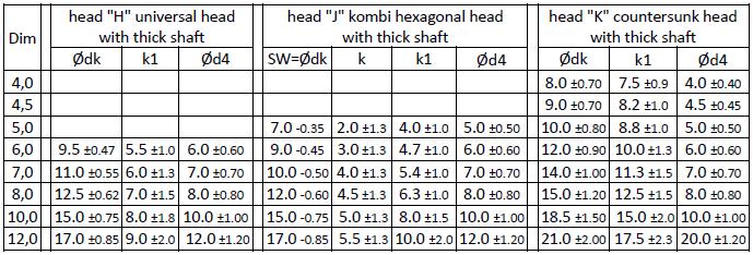
11 Page 11, head H universal head with thick shaft head J kombi hexagonal head with thick shaft head K countersunk head with thick shaft 0-30 UKR (e.g. 6) drive types see Annex UKR (e.g. 6) head L cylinder head head M countersunk washer head N SuperSenkFix head Screw head geometry Annex 1
12 Page 12, head P hexagonal head with washer alternative with T-drive head R hexagonal head with large washer alternative with T-drive drive types see Annex 5 drive types see Annex 5 head S round pan head with thick shaft head T 60 countersunk head Screw head geometry Annex 1


13 Page 13, Screw head geometry Annex 1

14 Page 14, Screw head geometry Annex 1

15 Page 15, shank without friction part 0 shank with friction part 1 shank with alternative friction part 1 Number of flanks: screw assembly: screw head, support thread, shank with friction part see Annex 0 for screws with 2 threads b1 = 0 for thread E with d = 8 mm: see Annex 3 Øds = 6.4 ± 0.29 mm Shank and compressor geometry Annex 2
 thread types according to Annex 3 lsp (lp) according to Annex 4 Shank and compressor geometry Annex")
16 Page 16, with compressor 1 with alternative compressor 2 with alternative compressor 3 without compressor 0 number of flanks: 4-8 lv = 2P to 4P (1P for l 100) thread types according to Annex 3 lsp (lp) according to Annex 4 Shank and compressor geometry Annex 2
17 Page 17, thread A single thread thread B coarse thread thread C double thread thread D HiLo thread thread E hardwood thread thread E alternative with rounded thread ground Thread and cutting groove geometry Annex 3


18 Page 18, thread with cutting groove 1 (without cutting groove 0 ) Ød similar for all threads Thread and cutting groove geometry Annex 3
19 Page 19, point A regular point point B milling thread point C half cut point D scraping point E drill point (alternative with thread) point F drill point Point geometry Annex 4

20 Page 20, lsp (lp) = similar for all points P and di according to Annex 3 Point geometry Annex 4

21 Page 21, KS-Drive T-Drive T-Drive alternative with Pin head labelling optional alternative UKR e.g.: supplier code, label e.g.: length Drive types and head labeling Annex 5
22 Page 22, Table A6.1: Characteristic head pull-through capacities of Schmid screws RAPID, STARDRIVE and SP in solid softwood or glued laminated timber for 90 heads; head diameter 8 to 21 mm Group 1 Head diameter (90 heads) 1) Product characteristic Characteristic head pullthrough parameter (ρk = 350 kg/m³) fhead,k N/mm² ) Linear interpolation is possible for head diameters in between the stated values Table A6.2: Characteristic head pull-through capacities of Schmid screws RAPID, STARDRIVE and SP in solid softwood or glued laminated timber for washers and 180 heads; washer diameter 14 to 42 mm Group 2 Head diameter (180 heads) 1) Product characteristic Characteristic head pullthrough parameter (ρk = 350 kg/m³) fhead,k fhead,k head N N/mm² ) Linear interpolation is possible for head diameters in between the stated values Table A6.3: Characteristic load bearing capacities of Schmid screws RAPID, STARDRIVE and SP for product characteristic group A; screw diameter 4 to 6 mm Product characteristic group A Screw diameter Product characteristic Max. length lmax mm Characteristic tensile strength ftens,k kn Characteristic yield moment My,k Nm Characteristic withdrawal parameter angle screw-axis to grain: 90 (ρk = 350 kg/m³) fax,k,90 N/mm² Characteristic yield strength fy,k N/mm² 900 Characteristic torsional strength ftor,k Nm Insertion moment (ρk = 450 kg/m³) Rtor,m Nm Characteristic data of the screws Annex 6
23 Page 23, Table A6.4: Characteristic load bearing capacities of Schmid screws RAPID, STARDRIVE and SP for product characteristic group A; screw diameter 7 to 12 mm Product characteristic group A Screw diameter Product characteristic Max. length lmax mm Characteristic tensile strength ftens,k kn Characteristic yield moment My,k Nm Characteristic withdrawal parameter angle screw-axis to grain: 90 (ρk = 350 kg/m³) fax,k,90 N/mm² Characteristic yield strength fy,k N/mm² 900 Characteristic torsional strength ftor,k Nm Insertion moment (ρk = 450 kg/m³) Rtor,m Nm Characteristic data of the screws Annex 6
24 Page 24, Table A6.5: Characteristic load bearing capacities of Schmid screws RAPID, STARDRIVE and SP for product characteristic group B; screw diameter 4 to 10 mm Product characteristic group B Screw diameter Product characteristic Max. length Characteristic tensile strength Characteristic yield moment carbon steel lmax mm stainless steel carbon steel ftens,k kn stainless steel carbon steel My,k Nm stainless steel Characteristic withdrawal parameter angle screw-axis to grain: 90 (ρk = 350 kg/m³) fax,k,90 N/mm² Characteristic yield strength fy,k N/mm² 900 (carbon steel) 735 (stainless steel) Characteristic torsional strength carbon steel ftor,k Nm stainless steel Insertion moment carbon steel ρk = 450kg/m³ stainless steel ρk = 480kg/m³ Rtor,m Nm Characteristic data of the screws Annex 6
25 Page 25, Table A6.6: Characteristic load bearing capacities of Schmid screws RAPID, STARDRIVE and SP for product characteristic group C; screw diameter 4 to 10 mm Product characteristic group C Screw diameter Product characteristic Max. length lmax mm Characteristic tensile strength ftens.k kn Characteristic yield moment My.k Nm Characteristic withdrawal parameter angle screw-axis to grain: 90 (ρk = 350 kg/m³) fax.k.90 N/mm² Characteristic yield strength fy.k N/mm² 900 Characteristic torsional strength ftor.k Nm Insertion moment (ρk = 450 kg/m³) Rtor.m Nm Characteristic data of the screws Annex 6
26 Page 26, Table A6.7: Characteristic load bearing capacities of Schmid screws RAPID, STARDRIVE and SP for product characteristic group D; screw diameter 6 to 10 mm Product characteristic group D Screw diameter Product characteristic Max. length lmax mm Characteristic tensile strength ftens.k kn Characteristic yield moment My.k Nm Characteristic withdrawal parameter angle screw-axis to grain: 90 (ρk = 350 kg/m³) fax.k.90 N/mm² Characteristic yield strength fy.k N/mm² 950 Characteristic torsional strength ftor.k Nm Insertion moment (ρk = 450 kg/m³) Rtor.m Nm Half cut Rtor.m. HT Nm Slip modulus Kser N/mm see A.6.4 Characteristic data of the screws Annex 6
27 Page 27, Table A6.8: Characteristic load bearing capacities of Schmid screws RAPID, STARDRIVE and SP for product characteristic group E; screw diameter 8 to 12 mm Product characteristic group E Screw diameter Product characteristic Max. length Characteristic tensile strength Characteristic yield moment carbon steel lmax mm stainless steel carbon steel ftens.k kn stainless steel carbon steel My.k Nm stainless steel Characteristic withdrawal parameter angle screw-axis to grain: 90 (ρk = 350 kg/m³) fax.k.90 N/mm² Characteristic yield strength fy.k N/mm² 950 (carbon steel) 657 (stainless steel) Characteristic torsional strength carbon steel ftor.k Nm stainless steel Insertion moment carbon steel ρk = 450kg/m³ stainless steel ρk = 480kg/m³ Rtor.m.HT Nm Slip modulus Kser N/mm see A.6.4 Characteristic data of the screws Annex 6
28 Page 28, Table A6.9: Characteristic load bearing capacities of Schmid screws RAPID for product characteristic group F; screw diameter 8 mm Product characteristic group F Screw diameter Product characteristic 8 Max. length lmax mm 240 Characteristic tensile strength ftens,k kn 32.8 Characteristic yield moment My,k Nm 42.8 Characteristic withdrawal parameter angle screw-axis to grain: 90 and 0 (ρk,bu = 625 kg/m³ and ρk,fsh-bu = 740 kg/m³) fax,k,bu,90 N/mm² 38.7 fax,k,bu, fax,k,fsh-bu, fax,k,fsh-bu, Characteristic yield strength fy,k N/mm² 950 Characteristic torsional strength ftor,k Nm 39.5 Insertion moment (ρk = 740 kg/m³) Rtor,m,HT Nm ftor,k > 1.5 * Rtor,m,HT Slip modulus angle screw-axis to grain: 90 and 0 (ρk,bu = 625 kg/m³ and ρk,fsh-bu = 740 kg/m³) Kser,ax,Bu, Kser,ax,Bu, N/mm Kser,ax,FSH-Bu, Kser,ax,FSH-Bu, Characteristic data of the screws Annex 6
29 Page 29, A.6.1 General The characteristic load bearing capacities in Tables A6.1 to A6.8 are given for timber of strength class C24 according to EN 338 ( k = 350 kg/m³). For timber with a deviating density the characteristic withdrawal parameter as well as the characteristic head pull-through parameter shall be corrected by the factor k dens k Where ρ k Characteristic density of timber in kg/m 3 The minimum penetration length of screws in the load-bearing wood-based members shall be 4 d. A bending angle of 45 must be reached for all screws. A.6.2 Characteristic withdrawal parameter For angles 0 45 between screw-axis and direction of wood-fibre, f ax,k,α is obtained by k f f ax, k, ax ax, k, 90 with k ax 0.7 0,3 45 For angles between screw-axis and direction of wood-fibre, f ax,k,α remains constant. A.6.3 Characteristic head pull-through capacity for wood based panels The characteristic value of the head pull-through parameter for a characteristic density of 380 kg/m³ of the timber and for the following wood based panels - Plywood according to EN 636 and EN 13986, - Oriented strand boards, OSB, according to EN 300 and EN 13986, - Solid wood panels according to EN and EN 13986, - Particleboard according to EN 312 and EN 13986, - Fibreboards according to EN 622-2, EN and EN 13986, - Cement-bonded particle boards according to EN and EN with thicknesses of more than 20 mm is f head,k = 10 N/mm² Characteristic data of the screws Annex 6
30 Page 30, For wood based panels with a thickness between 12 mm and 20 mm the characteristic value of the head pull-through parameter is f head,k = 8 N/mm² For plywood with a minimum of 7 layers and a minimum thickness of 18 mm, the characteristic value of the head pull-through parameter for a characteristic density of 490 kg/m³ is (d k 18.8 mm) f head,k = 16 N/mm² For wood based panels with a thickness of less than 12 mm the characteristic head pullthrough capacity shall be based on a characteristic value of the head pull-through parameter of 8 N/mm², and limited to 400 N complying with the minimum thicknesses of the wood based panels of 1.2 d, with d as outer thread diameter. In addition the minimum thicknesses of Table A6.10 apply. Table A6.10 Minimum thicknesses of wood based panels Wood based panel Minimum thickness in mm Plywood 6 Oriented strand board, OSB 8 Solid wood panels 12 Particleboard 8 Fibreboards 6 Cement-bonded particle boards 8 A.6.4 Slip modulus for mainly axially loaded screws The axial slip modulus K ser for the serviceability limit state used for connection of individual members in bending beams under flexible jointing shall be taken for screws independent of angle to the grain as K 25 d ser l ef in N/mm for softwood K 30 d ser l ef in N/mm for hardwood with d = outer thread diameter of the screw in mm l ef = penetration length of the threaded part of the screw in the timber member in mm Characteristic data of the screws Annex 6
31 Page 31, A.6.5 Compressive loading for fully threaded screws (unsupported buckling, e.g. soft insulating materials) The design load carrying capacity for with a full thread for an angle between screw-axis and direction of wood-fibre for compressive loading is given as F c,, Rd min F ax,, d ; F ki, d in N with F f ax,, d ax, d, d l ef f ax,d, = design value of the axial withdrawal capacity of the threaded part of the screw calculated from the characteristic values given in Table A6.3 to A6.8 in N/mm² d = outer thread diameter of the screw in mm l ef = penetration length of the threaded part of the screw in the timber member in mm N pl, k Fki, d Fki, k / M M 1 1 for 0. 2 or for N N pl, k ki, k 2 d i N pl, k f y, k in N 4 d i = inner thread diameter for fully threaded screw, shank diameter d s for screws with 2 threads f, = characteristic yield strength of the screw according to Table A6.3 to A6.8 y k N, = characteristic ideal elastic buckling load N ki k c E I ki, k h s s in N c h = elastic foundation of the screw Characteristic data of the screws Annex 6
32 Page 32, 90 c h ( d) k in N/mm² 180 k = characteristic density of the wood-based member in kg/m³ = angle between screw axis and grain direction, E s I s d 64 4 i = bending stiffness in N/mm² A.6.6 Compression reinforcement (screws in timber) The compression force shall evenly be distributed to the screws used as compression reinforcement. The screws are driven into the timber member perpendicular to the contact surface under an angle between the screw axis and the grain direction of 45 to 90. The screw heads must be flush with the timber surface. Reinforcing screws for wood-based panels are not covered by this European Technical Assessment. For the design of reinforced contact areas the following conditions shall be met independently of the angle between the screw axis and the grain direction. The design resistance of a reinforced contact area is: R 90, d where: k min c,90 B l ef,1 f c,90, d B l ef,2 f n min F c,90, d ax,, d ; F ki, d k c,90 = parameter according to EN , B = bearing width in mm l ef,1 = effective contact length according to EN , in mm f c 90, d, = design compressive strength perpendicular to the grain (EN 338/EN ) in N/mm² n n 0 n 90 n = number of reinforcing screws n 0 = number of reinforcing screws arranged in a row parallel to the grain n 90 = number of reinforcing screws arranged in a row perpendicular to the grain l ef,2 = effective contact length in the plane of the screw tips in mm Characteristic data of the screws Annex 6
33 Page 33, l n 1 a minl a l ef, 2 ef 0 1 ef ; 1, c l ef, 2 lef n a 1 end supports intermediate supports l ef = penetration length of the threaded part of the screw in the timber member in mm a 1,c = end distance of the centre of gravity of the threaded part in the timber member in mm Characteristic data of the screws Annex 6
34 Page 34, A.6.7 Tensile reinforcement perpendicular to the grain Fully threaded screws may be used as tensile reinforcement perpendicular to the grain of the timber members. The screws are driven into the timber member under an angle between the screw axis and the grain direction of 90. A minimum of two screws shall be used for tensile reinforcement perpendicular to the grain. Only one screw may be used when the minimum penetration depth of the screws below and above the potential crack is 20 d where d is the outer thread diameter of the screw. Tension reinforcement for transverse connections and notches may be designed according to F 90 F ax, Rd for transverse connections with (1 ) 2 (1 ) Rd 1.3 for notches with where F ax V d F ax, h e h f ax, d d l2, Rd min axial capacity of the reinforcement in N Ft, Rd a h F 90 = design value of the force acting in the connection perpendicular to the grain of the timber members in N V d = design value of the shear force in N f ax, d = design value of the withdrawal capacity of the threaded part of the screw in N/mm² l 2 = smaller value of the penetration depth below or above the potential crack (l 2,a or l 2,t ) in mm F, = design value of the tensile resistance of the screw in N t Rd Characteristic data of the screws Annex 6
35 Page 35, Tension reinforcement of openings may be designed according to F t, V, d Ft, M, d Fax, d where F V d hd h 4 h h t, V, d 3 F t V, d F 2 d 2, = design value of tension force perpendicular to the grain due to lateral force in N t, M, d F t M, d V d h h d M d h r M h r d, = design value of tension force perpendicular to the grain due to bending moment in N = design value of the lateral force in the edge of the opening in N = height of the timber member in mm = height of the opening for rectangular openings or 70 % of opening diameter for circular openings in mm = design value of bending moment in the edge of the opening in Nmm = min (h ro ; h ru ) for rectangular openings or min (h ro h d ; h ru h d ) for circular openings in mm d ax F, = design load bearing capacity for the screws perpendicular to the grain with l ef as the smaller length above or below the potential crack in N Characteristic data of the screws Annex 6
36 Page 36, area of crack building area of crack building Characteristic data of the screws Annex 6

37 Page 37, A.6.8 Shear reinforcement Fully threaded screws may be used as shear reinforcement of solid timber, glued laminated timber and glued solid timber of softwood. The provisions are valid for straight beams with constant rectangular cross-section. The screws are driven into the timber member under an angle between the screw axis and the grain direction of 45. A minimum of four screws shall be used for shear reinforcement in a line parallel to the grain whereas the spacing between the screws shall not exceed the depth h of the timber member. If the screws are arranged in one line parallel to the grain, it shall be done centrically in relation to the beam width. The effect of the reinforcement is limited to the shaded part of the timber member. Outside this area sufficient shear strength of the cross section must be verified. Shear reinforcement may be designed according to d f v, d k where H d = design value of shear stress in N/mm² f v, d = design value of shear strength in N/mm² k , d , d F ax, d 90, d design value of stress perpendicular to the grain in N/mm² 2 b a b a 1 F V d ax, d 1 = with of the timber member in mm = spacing of screws parallel to the grain in mm 2 1 H Vd a h = design shear force in N 1 Characteristic data of the screws Annex 6
38 Page 38, h G d H G b = height of the timber member in mm 2 G b d h k ax a1 EA S = mean value of shear modulus of the timber member in N/mm² = outer thread diameter of the screw in mm k ax = connection stiffness between screw and timber member in N/mm³, k ax = 12.5 N/mm³ for RAPID fully threaded screw with d = 8 mm E EA S 4 d 1 2 d 1 axial stiffness of one screw in N = inner thread diameter of the screw in mm The axial capacity of the screw shall fulfill Fax, d 1 F ax, Rd where F ax f, Rd min ax, d f d l tens, d ef f ax, d = design value of the withdrawal parameter of the threaded part of the screw in N/mm² l ef = effective penetration length with 50 % of the threaded part length of the screw in the timber member in mm f, = design tensile strength of the screw in N tens d Characteristic data of the screws Annex 6
39 Page 39, A.7.1 General For screws with d 8 mm the minimum width/thickness for structural members shall be in accordance with Table A7.1. Minimum thickness for structural members is t = 24 mm for screws with d < 8 mm. Table A7.1 Minimum width/thickness for structural members Screw diameter Minimum thickness t for structural members mm A.7.2 Laterally and/or axially loaded screws For in predrilled and non-predrilled holes, the minimum spacing, end and edge distances shall be specified according to EN Here, the outer thread diameter d shall be considered. For screws in non-predrilled holes, the minimum distances for loaded and unloaded ends shall be 15 d for screws with outer thread diameter d 8 mm and timber thickness t < 5 d. Minimum distances from the unloaded edge perpendicular to the grain may be reduced to 3 d also for timber thickness t < 5 d, if the spacing parallel to the grain and the end distance is at least 25 d. A.7.3 Only axially loaded screws For with d 8 mm or provided with a half cut or drill point which are loaded only axially, the following minimum spacing, end and edge distances apply alternatively for a minimum timber thickness of t = 12 d in non-predrilled holes: Spacing a 1 in a plane parallel to the grain: a 1 = 5 d Spacing a 2 perpendicular to a plane parallel to the grain: a 2 = 5 d End distance of the centre of gravity of the threaded part in the timber member: a 1,c = 5 d Edge distance of the centre of gravity of the threaded part in the timber member: a 2,c = 4 d Spacing a 2 can be reduced till 2.5 d (3 d) if the product of spacing a 1 times a 2 = 25 d² (21 d²) can be kept for every screw. Annex 7 Spacing, end and edge distances of the screws and minimum thickness of the wood based material
40 Page 40, A.8.1 Fastening of thermal insulation material (on top of rafters and facades) RAPID, STARDRIVE and SP with an outer thread diameter of at least 6 mm and lengths between 120 mm and 600 mm may be used for fixing of thermal insulation material on rafters or on wood-based members in vertical facades. Screw head E and L according to Annex 1 are excluded from fixing wood-based panels on rafters with thermal insulation material as interlayer. The angle between grain direction and screw axis shall be 30 α 90. The thickness of the thermal insulation material is max. 400 mm. The thermal insulation material shall be applicable as insulation on top of rafters according to national provisions that apply at the installation site. The battens are made from solid timber strength class C24 according to EN 338 and EN The minimum thickness and width of the battens is: Table A8.1 Minimum thickness and width of the battens Screw diameter d in mm b min mm t min mm Instead of battens the following wood-based panels may be used to cover the thermal insulation material if they are suitable for that use: Plywood according to EN 636 and EN 13986, Oriented Strand Board, OSB according to EN 300 and EN 13986, Particleboard according to EN 312 and EN Fibreboards according to EN 622-2, EN and EN The minimum thickness of the wood-based panels shall be 22 mm. The word batten in the following includes the meaning of the above mentioned wood-based panels. The substructure is made from solid timber strength class C24 according to EN 338 and EN , cross laminated timber according to European Technical Assessments or laminated veneer lumber according to EN The minimum width is b min = 60 mm, for screws with an outer thread diameter of 12 mm the minimum width b min = 80 mm. The spacing between screws e s shall be not more than 1.75 m. Fastening of thermal insulation material Annex 8
41 Page 41, Friction forces shall not be considered for the design of the characteristic axial capacity of the screws. The anchorage of wind suction forces as well as the bending stresses of the battens or the boards, respectively, shall be considered for design. Screws perpendicular to the grain of the rafter (angle α = 90 ) may be arranged if necessary. Design may follow EN if nothing different is specified below. The two following systems are possible for 0 β 90 : - System 1: Alternately inclined screws (only screws with full thread, double thread) A according to structural analysis, B 50 mm - System 2: Parallel inclined screws (all screws, in case of compression resistant insulation material 0.05 N/mm²) A according to structural analysis Fastening of thermal insulation material Annex 8
42 Page 42, Fastening of thermal insulation material Annex 8
43 Page 43, A.8.2 Alternately inclined screws (only screws with full thread) The screws are predominantly loaded in withdrawal or compression, respectively. Only systems with battens are allowed. Design For design of thermal insulation systems in terms of number and spacing of the screws the following characteristic values of tensile or compressive load bearing capacity may be taken into account: R ax f, k min f where: ax, k, ax, k, d l d l ef, L ef, UK in N f ax,k, = characteristic value of the axial withdrawal parameter of the threaded part of the screw in the batten, f ax,k, does not apply for wood-based panels = angle between screw axis and grain direction of batten or substructure d = outer thread diameter of the screw in mm l, = penetration length of the threaded part of the screw in the batten in mm; ef L ef UK the screw head length k may be taken into account for tension load (not for compressive loading) l, = penetration length of the threaded part of the screw in the substructure in mm; 60 mm For compressive loading the design compressive load bearing capacity shall not exceed the buckling capacity of the screws according to A.6.5. N pl, d A.8.3 Parallel inclined screws The screws are predominantly loaded in tension whereas corresponding thermal insulation material is loaded in compression. The minimum compression stress of the thermal insulation material at 10 % deformation, measured according to EN 826, shall be σ (10%) 0.05 N/mm². Hereby systems with battens or wood-based panels may be used. Design For design of thermal insulation systems in terms of number and spacing of the screws the following characteristic withdrawal parameter may be taken into account: Fastening of thermal insulation material Annex 8
44 Page 44, f ax, k, d lef R f ax, k min max f ax, k, where:, UK head, k l k d ef, L 1 2 k k d 2 in N f ax,k, = characteristic value of the axial withdrawal parameter of the threaded part of the screw in the batten, f does not apply for wood-based head k panels ax,k, f, = characteristic head pull-through parameter according to Tables A6.1 k k min 220 d Dä. 1 min 10% 0.12 and A6.2 d Dä. = thickness of thermal insulation material in mm = compressive stress of thermal insulation material at 10 % strain in N/mm² 10 % Fastening of thermal insulation material Annex 8


45 Page 45, A.9.1 Connections between timber and a steel member The screws may be used in connections between timber and a steel member, e.g. wind bracing or tensile splice in solid timber, glued laminated timber and glued solid timber of softwood. The screws are driven into the timber member under an angle between the screw axis and the grain direction of 30 α 90. Sufficient contact of the screw head must be ensured. This is fulfilled for countersunk heads with countersunk washer as well as heads with a flat bottom side (e.g. pan head, washer head, SuperSenkFix, ) for 90 drillings. Alternatively, countersunk head screws may be used in 90 countersunk drillings where d Fase d 1.5 in mm d = diameter of the drilling in mm d Fase = diameter of the chamfer in mm The diameter d of the drilling must be greater than the diameter of the screw. Connections between timber and steel Annex 9
46 Page 46, For countersunk head screws with a diameter 8 mm d 12 mm used in countersunk drillings under an angle 30 α < 90 the diameter d k must be greater than the head diameter. Hereby, the following minimum thickness s of the steel member underneath the screw head is required: α 45 s 3mm 30 α 45 s 2 mm Design for equally tightened screws (torque controlled) in a steel member under an angle 30 α 45 may follow: F F where: ax, (cos * sin) F = load bearing capacity of inclined screws in N F = axial load bearing capacity of the screw in N with 0. 9 n ax, = angle between screw axis and grain direction = friction coefficient between steel member and timber surface, 0. 3 For symmetrically arranged steel members on both sides of the timber member, tension in transverse direction must be verified if the overlapping of the crossed screws in the middle of the axis is lower than 4 d. n ef Connections between timber and steel Annex 9
47 Page 47, European Assessment Document EAD Screws for use in timber constructions EN 300 ( ), Oriented Strand Boards (OSB) Definitions, classification and specifications EN 312 ( ), Particleboards Specifications EN 338 ( ), Structural timber Strength classes EN ( ) +AC ( ), Fibreboards Specifications Part 2: Requirements for hardboards EN ( ), Fibreboards Specifications Part 3: Requirements for medium boards EN ( ), Cement-bonded particleboards Specifications Part 1: General requirements EN 636 ( ), Plywood Specifications EN 826 ( ), Thermal insulating products for building applications Determination of compression behaviour EN ( ) +A1 ( ), Eurocode 3 Design of steel structures Part 1-4: General rules Supplementary rules for stainless steels EN ( ), +AC (6.2006), +A1 ( ), +A2 ( ), Eurocode 5 Design of timber structures Part 1-1: General Common rules and rules for buildings EN ( ), Stainless steels Part 1: List of stainless steels EN 13353:2008+A1 ( ), Solid wood panels (SWP) Requirements EN 13986:2004+A1 ( ), Wood-based panels for use in construction - Characteristics, evaluation of conformity and marking EN ( ), Timber structures Glued laminated timber and glued solid timber Requirements EN ( ), Timber structures Strength graded structural timber with rectangular cross section Part 1: General requirements EN ( ), Timber structures Structural laminated veneer lumber Requirements Reference documents Annex 10
Verbindungselemente Engel GmbH Weltestraße Weingarten DEUTSCHLAND. Manufacturing plant 74437, , ,
 European Technical Assessment ETA-13/0536 of 20 February 2018 - Original version in German language General Part Technical Assessment Body issuing the European Technical Assessment: Trade name of the construction
European Technical Assessment ETA-17/1005 of
 ETA-Danmark A/S Göteborg Plads 1 DK-2150 Nordhavn Tel. +45 72 24 59 00 Fax +45 72 24 59 04 Internet www.etadanmark.dk Authorised and notified according to Article 29 of the Regulation (EU) No 305/2011
European Technical Assessment. ETA-16/0902 of 17 March English translation prepared by DIBt - Original version in German language.
 European Technical Assessment ETA-16/0902 of 17 March 2017 - Original version in German language General Part Technical Assessment Body issuing the European Technical Assessment: Trade name of the construction
European Technical Assessment ETA-12/0197 of 12/07/2017
 ETA-Danmark A/S Göteborg Plads 1 DK-2150 Nordhavn Tel. +45 72 24 59 00 Fax +45 72 24 59 04 Internet www.etadanmark.dk Authorised and notified according to Article 29 of the Regulation (EU) No 305/2011
European Technical Assessment. ETA-15/0667 of Member of. General part
 INSTITU Schenkenstrasse 4 T +43 1 533 65 50 1010 Vienna Ι Austria F +43 1 533 64 23 www.oib.or.at Ι mail@oib.or.at Designated according to Article 29 of Regulation (EU) No 305/2011 Member of www.eota.eu
Österreichisches Institut für Bautechnik Schenkenstrasse Vienna Austria T F
 Authorised and notified according to Article 10 of the Council Directive 89/106/EEC of 21 December 1988 on the approximation of laws, regulations and administrative provisions of Member States relating
European Technical Assessment ETA-13/0029 of 11/07/2017
 ETA-Danmark A/S Göteborg Plads 1 DK-2150 Nordhavn Tel. +45 72 24 59 00 Fax +45 72 24 59 04 Internet www.etadanmark.dk Authorised and notified according to Article 29 of the Regulation (EU) No 305/2011
European Technical Assessment ETA-11/0024 of 08/07/2016
 ETA-Danmark A/S Göteborg Plads 1 DK-2150 Nordhavn Tel. +45 72 24 59 00 Fax +45 72 24 59 04 Internet www.etadanmark.dk Authorised and notified according to Article 29 of the Regulation (EU) No 305/2011
REISSER-Schraubentechnik GmbH Fritz-Müller-Straße Ingelfingen-Criesbach DEUTSCHLAND
 European Technical Assessment ETA-11/0106 of 20 June 2016 - Original version in German language General Part Technical Assessment Body issuing the European Technical Assessment: Trade name of the construction
European Technical Approval ETA-12/0114
 ETA-Danmark A/S Kollegievej 6 DK-2920 Charlottenlund Tel. +45 72 24 59 00 Fax +45 72 24 59 04 Internet www.etadanmark.dk Authorised and notified according to Article 10 of the Council Directive 89/106/EEC
European Technical Assessment ETA-11/0024 of 02/03/2017
 ETA-Danmark A/S Göteborg Plads 1 DK-2150 Nordhavn Tel. +45 72 24 59 00 Fax +45 72 24 59 04 Internet www.etadanmark.dk Authorised and notified according to Article 29 of the Regulation (EU) No 305/2011
European Technical Approval ETA-11/0024
 ETA-Danmark A/S Kollegievej 6 DK-2920 Charlottenlund Tel. +45 72 24 59 00 Fax +45 72 24 59 04 Internet www.etadanmark.dk Authorised and notified according to Article 10 of the Council Directive 89/106/EEC
European Technical Approval ETA-11/0283
 European Technical Approval ETA-11/0283 - Original version in German language Handelsbezeichnung Trade name Zulassungsinhaber Holder of approval Zulassungsgegenstand und Verwendungszweck Generic type and
European Technical Assessment ETA-04/0038 English translation prepared by DIBt. Page 2 of July 2016
 European Technical Assessment ETA-04/0038 Page 2 of 15 29 July 2016 The European Technical Assessment is issued by the Technical Assessment Body in its official language. Translations of this European
European Technical Assessment. ETA-14/0426 of 21 December English translation prepared by DIBt - Original version in German language
 European Technical Assessment ETA-14/0426 of 21 December 2016 - Original version in German language General Part Technical Assessment Body issuing the European Technical Assessment: Trade name of the construction
European Technical Approval ETA-07/0212
 ETA-Danmark A/S Kollegievej 6 DK-2920 Charlottenlund Tel. +45 45 76 20 20 Fax +45 45 76 33 20 Internet www.etadanmark.dk Authorised and notified according to Article 10 of the Council Directive 89/106/EEC
European Technical Approval ETA-08/0165
 ETA-Danmark A/S Kollegievej 6 DK-2920 Charlottenlund Tel. +45 72 24 59 00 Fax +45 72 24 59 04 Internet www.etadanmark.dk Authorised and notified according to Article 10 of the Council Directive 89/106/EEC
European Technical Assessment. ETA-14/0426 of 15 December English translation prepared by DIBt - Original version in German language
 European Technical Assessment ETA-14/0426 of 15 December 2014 - Original version in German language General Part Technical Assessment Body issuing the European Technical Assessment: Trade name of the construction
Powers Trak-It XH and HD nails for gas actuated tools C4 and C5
 European Technical Assessment ETA-12/0188 of 7 October 2016 - Original version in German language General Part Technical Assessment Body issuing the European Technical Assessment: Trade name of the construction
European Technical Assessment ETA 15/0029 of 12/06/2017
 RISE Research Institutes of Sweden AB RISE Certifiering Box 553 SE-371 23 Karlskrona Sweden Member of www.eota.eu Tel: +46 10 516 63 00 Web: www.ri.se Mail: certifiering@ri.se European of 12/06/2017 General
European Technical Approval ETA-08/0183
 ETA-Danmark A/S Kollegievej 6 DK-2920 Charlottenlund Tel. +45 72 24 59 00 Fax +45 72 24 59 04 Internet www.etadanmark.dk Authorised and notified according to Article 10 of the Council Directive 89/106/EEC
European Technical Approval ETA-13/0630
 ETA-Danmark A/S Kollegievej 6 DK-2920 Charlottenlund Tel. +45 72 24 59 00 Fax +45 72 24 59 04 Internet www.etadanmark.dk Authorised and notified according to Article 10 of the Council Directive 89/106/EEC
European Technical Approval ETA-10/0413
 ETA-Danmark A/S Kollegievej 6 DK-2920 Charlottenlund Tel. +45 72 24 59 00 Fax +45 72 24 59 04 Internet www.etadanmark.dk Authorised and notified according to Article 10 of the Council Directive 89/106/EEC
European Technical Assessment. ETA-13/0183 of 29 June English translation prepared by DIBt - Original version in German language.
 European Technical Assessment ETA-13/0183 of 29 June 2017 - Original version in German language General Part Technical Assessment Body issuing the European Technical Assessment: Trade name of the construction
Klaus-Fischer-Straße Waldachtal DEUTSCHLAND EAD This version replaces ETA-15/0352 issued on 12 April 2016
 European Technical Assessment ETA-15/0352 of 30 October 2018 - Original version in German language General Part Technical Assessment Body issuing the European Technical Assessment: Trade name of the construction
European Technical Assessment. ETA-12/0056 of General Part. Technical Assessment Body issuing the ETA:
 Member of SINTEF Building and Infrastructure P.O.Box 124 Blindern NO-0314 Oslo, Norway Phone +47 40 00 51 00 e-mail: certification@sintef.no www.eota.eu European Technical Assessment ETA-12/0056 of 2018-12-15
European Technical Approval ETA-10/0038
 ETA-Danmark A/S Kollegievej 6 DK-2920 Charlottenlund Tel. +45 72 24 59 00 Fax +45 72 24 59 04 Internet www.etadanmark.dk Authorised and notified according to Article 10 of the Council Directive 89/106/EEC
English translation authorized by DIBt Original version in German language
 Date: Reference: 12/02/2014 I 36-1.14.4-104/13 English translation authorized by DIBt Original version in German language Approval number: Validity Z-14.4-407 from: 1 February 2014 Applicant: IFBS Europark
Klaus-Fischer-Straße Waldachtal DEUTSCHLAND EAD This version replaces ETA-07/0025 issued on 14 May 2018
 European Technical Assessment ETA-07/0025 of 28 August 2018 - Original version in German language General Part Technical Assessment Body issuing the European Technical Assessment: Trade name of the construction
Timber fasteners for structural use
 TECHNICAL INFORMATION TIMBER FASTENERS FOR STRUCTURAL USE TESTING AND CERTIFICATION TI-17 V1 Timber fasteners for structural use Testing and certification 01 INTRODUCTION Timber fasteners for structural
LOAD CARRYING CAPACITY OF METAL DOWEL TYPE CONNECTIONS OF TIMBER STRUCTURES
 Vol. 10, Issue /014, 51-60 DOI: 10.478/cee-014-0011 LOAD CARRYING CAPACITY OF METAL DOWEL TYPE CONNECTIONS OF TIMBER STRUCTURES Jozef GOCÁL 1,* 1 Department of Structures and Bridges, Faculty of Civil
European Technical Assessment ETA-04/0101 English translation prepared by DIBt. Page 2 of 12 1 March 2018
 European Technical Assessment ETA-04/0101 Page 2 of 12 1 March 2018 The European Technical Assessment is issued by the Technical Assessment Body in its official language. Translations of this European
STRUCTURAL TIMBER DESIGN
 STRUCTURAL TIMBER DESIGN to Eurocode 5 2nd Edition Jack Porteous BSc, MSc, DIC, PhD, CEng, MIStructE, FICE Director lack Porteous Consultancy and Abdy Kernlani BSc, MSc, PhD, CEng, FIStructE, FIWSc Professor
European Technical ETA-13/1038 Assessment of 26 January 2018 General Part
 European Technical Assessment ETA-13/1038 of 26 January 2018 - Original version in German language General Part Technical Assessment Body issuing the European Technical Assessment: Trade name of the construction
Tensile strength of ASSY plus VG screws wood-wood (softwood)
") Tensile strength of ASSY plus VG screws wood-wood (softwood) STRENGTHENS THE WOOD - INSTEAD OF SPLITTING IT 23.05.2017 Table of contents for tensile strength Determining the tensile strength - Table values
Tensile strength of ASSY plus VG screws wood-wood (softwood) STRENGTHENS THE WOOD - INSTEAD OF SPLITTING IT 23.05.2017 Table of contents for tensile strength Determining the tensile strength - Table values
Statement for nail plate LL13 Combi
 STATEMENT NO VTT-S-0369-17 1 (5) Request by Order Contact person Ristek Oy Askonkatu 11 FI-15110 Lahti 15.3.017 Kimmo Köntti VTT Expert Services Ltd Ari Kevarinmäki P.O. Box 1001, FI-0044 VTT Tel. +358
Glued laminated timber beams repair.
 Glued laminated timber beams repair. Master s Degree Extended Abstract Ricardo Cardoso Henriques da Silva Keywords: glulam, delamination, self-tapping screw, plywood, repair November 2014 1. INTRODUCTION
European Technical ETA-17/0513 Assessment of 27 October 2017 General Part
 European Technical Assessment ETA-17/0513 of 27 October 2017 - Original version in German language General Part Technical Assessment Body issuing the European Technical Assessment: Trade name of the construction
concrete Apolo MEA Befestigungssysteme GmbH Industriestraße Aichach DEUTSCHLAND Apolo MEA Befestigungssysteme GmbH, Plant2 Germany
 European Technical Assessment ETA-09/0373 of 1 June 2018 - Original version in German language General Part Technical Assessment Body issuing the European Technical Assessment: Trade name of the construction
ANCHORING TECHNOLOGY CAST-IN CHANNELS PEC-TA
 ANCHORING TECHNOLOGY CAST-IN CHANNELS PEC-TA European Technical Assessment ETA-16/0929 European Technical Assessment ETA-16/0929 of 9 August 2018 - Original version in German language General Part Technical
European Technical Assessment. ETA-18/0045 of 22 February English translation prepared by DIBt - Original version in German language
 European Technical Assessment ETA-18/0045 of 22 February 2018 - Original version in German language General Part Technical Assessment Body issuing the European Technical Assessment: Deutsches Institut
European Technical Assessment. ETA-18/0861 of 12 November English translation prepared by DIBt - Original version in German language
 European Technical Assessment ETA-18/0861 of 12 November 2018 - Original version in German language General Part Technical Assessment Body issuing the European Technical Assessment: Trade name of the construction
Eurocode EN Eurocode 3: 3 Design of steel structures. Part 1-1: General rules and rules for buildings
 Eurocode EN 1993-1-1 Eurocode 3: 3 Design of steel structures Part 1-1: General rules and rules for buildings Eurocode EN 1993-1-1 Eurocode 3 applies to the design of buildings and civil engineering works
Dowel-type fasteners. Timber Connections. Academic resources. Introduction. Deferent types of dowel-type fasteners. Version 1
 Academic resources Timber Connections Dowel-type fasteners Version 1 This unit covers the following topics: Deferent types of dowel-type fasteners Introduction There are four criteria designers should
Fosroc International Limited Drayton Manor Business Park Coles Road TAMWORTH STAFFORDSHIRE; B78 3XN GROSSBRITANNIEN EAD
 European Technical Assessment ETA-18/0586 of 12 July 2018 - Original version in German language General Part Technical Assessment Body issuing the European Technical Assessment: Trade name of the construction
European Technical Assessment. ETA-09/0338 of 18 June English translation prepared by DIBt - Original version in German language.
 European Technical Assessment ETA-09/0338 of 18 June 2018 - Original version in German language General Part Technical Assessment Body issuing the European Technical Assessment: Trade name of the construction
ICC-ES Evaluation Report
 ICC-ES Evaluation Report ESR-6 Reissued April, 009 This report is subject to re-examination in two years. www.icc-es.org (800) 4-6587 (56) 699-054 A Subsidiary of the International Code Council DIVISION:
Subject of approval: fischer concrete screw ULTRACUT FBS II for the temporary fastening of building site equipment
 Date: Reference: 13 July 2016 I 25-1.21.8-49/15 Approval number: Validity Z-21.8-2049 from: 13 July 2016 Applicant: fischerwerke GmbH & Co. KG Klaus-Fischer-Straße 1 72178 Waldachtal to: 13 July 2021 Subject
European Technical Approval ETA-10/0182
 European Technical Approval English translation prepared by DIBt - Original version in German language Handelsbezeichnung Trade name Zulassungsinhaber Holder of approval Zulassungsgegenstand und Verwendungszweck
European Technical Assessment. ETA-16/0929 of 3 July English translation prepared by DIBt - Original version in German language.
 European Technical Assessment ETA-16/0929 of 3 July 2017 - Original version in German language General Part Technical Assessment Body issuing the European Technical Assessment: Trade name of the construction
European Technical ETA-17/0130 Assessment of 4 December 2017 General Part
 European Technical Assessment ETA-17/0130 of 4 December 2017 - Original version in German language General Part Technical Assessment Body issuing the European Technical Assessment: Trade name of the construction
English translation authorized by DIBt Original version in German language
 Date: Reference: 29/04/2016 I 36-1.14.1-106/15 English translation authorized by DIBt Original version in German language Approval number: Validity Z-14.1-4 from: 1 February 2016 Applicant: IFBS Europark
American Institute of Timber Construction 7012 South Revere Parkway Suite 140 Centennial, CO Phone: 303/ Fax: 303/
 American Institute of Timber Construction 7012 South Revere Parkway Suite 140 Centennial, CO 80112 Phone: 303/792-9559 Fax: 303/792-0669 404.1. SCOPE STANDARD FOR RADIALLY REINFORCING CURVED GLUED LAMINATED
Z January 2017
 Certified True Translation 11 January 2017 I 36-1.14.4-100/16 Z-14.4-776 11 January 2017 30 September 2021 SFS intec GmbH In den Schwarzwiesen 2 61440 Oberursel, Germany Zulassungsnummer = Approval Number
European Technical Approval ETA-08/0007
 ETA-Danmark A/S Kollegievej 6 DK-2920 Charlottenlund Tel. +45 72 24 59 00 Fax +45 72 24 59 04 Internet www.etadanmark.dk Authorised and notified according to Article 10 of the Council Directive 89/106/EEC
European Technical Assessment. ETA-12/0198 of 19 June English translation prepared by DIBt - Original version in German language.
 European Technical Assessment ETA-12/0198 of 19 June 2017 - Original version in German language General Part Technical Assessment Boy issuing the European Technical Assessment: Trae name of the construction
HUS 6 Screw anchor, Redundant fastening
 HUS 6 Screw anchor, Anchor version HUS-A 6 Carbon steel Concrete Screw with hex head HUS-H 6 Carbon steel Concrete Screw with hex head HUS-I 6 Carbon steel Concrete Screw with hex head Benefits - Quick
Hanger bolts and solar fasteners in sandwich panels
 Hanger bolts and solar fasteners in sandwich panels Helmut Krüger 1, Thomas Ummenhofer 2, Daniel C. Ruff 3 Abstract For the energetic use of sunlit roofs, photovoltaic and solar thermal elements are mounted
DIVISION: WOOD, PLASTICS AND COMPOSITES SECTION: WOOD, PLASTIC, AND COMPOSITE FASTENINGS REPORT HOLDER:
 0 Most Widely Accepted and Trusted ICC ES Evaluation Report ICC ES 000 (800) 423 6587 (562) 699 0543 www.icc es.org ESR 2761 Reissued 10/2017 This report is subject to renewal 10/2019. DIVISION: 06 00
TEST SERIES TO EVALUATE THE STRUCTURAL BEHAVIOUR OF ISOBOARD OVER RAFTER SYSTEM
 TEST SERIES TO EVALUATE THE STRUCTURAL BEHAVIOUR OF ISOBOARD OVER RAFTER SYSTEM J A Wium Institute of Structural Engineering 19 November 2007 ISI2007-3 TEST SERIES TO EVALUATE THE STRUCTURAL BEHAVIOUR
BauBuche Fasteners and connections
 BauBuche Fasteners and connections Beech laminated veneer lumber Chapter under revision 05 BauBuche Fasteners and connections 05 04-18 - EN Sheet 1 / 10 Fasteners and connections Sheet CONTENTS 2 3 4 9
SCREWS WITH CONTINUOUS THREADS IN TIMBER CONNECTIONS
 SCREWS WITH CONTINUOUS THREADS IN TIMBER CONNECTIONS Prof. Dr.-Ing. H. J. Blaß, Dipl.-Ing. I. Bejtka Universität Karlsruhe (TH), Germany Abstract Screws, bolts and dowels loaded perpendicular to the fastener
Instruction Manual for installing
 Instruction Manual for installing Preloaded (HSFG) Bolting with TurnaSure DIRECT TENSION INDICATORS CE Marked EN 14399-9 TurnaSure LLC TABLE OF CONTENTS Introduction... 1 Theory of Preloaded Bolting Assemblies...
ALUMIDI. Concealed beam hanger with and without holes Aluminum alloy tridimensional perforated plate ALUMIDI - 01 CERTIFIED STEEL-ALUMINUM
 ALUMIDI Concealed beam hanger with and without holes Aluminum alloy tridimensional perforated plate CERTIFIED Available with and without holes. The 2200 mm model is also certified FIELD OF USE Timber-to-Timber
ESR-2648 Reissued May 1, 2012 This report is subject to renewal June 1, 2013.
 ICC-ES Evaluation Report ESR-2648 Reissued May 1, 2012 This report is subject to renewal June 1, 2013. www.icc-es.org (800) 423-6587 (562) 699-0543 A Subsidiary of the International Code Council DIVISION:
DIVISION: WOOD, PLASTICS AND COMPOSITES SECTION: WOOD, PLASTIC AND COMPOSITE FASTENINGS REPORT HOLDER: EVALUATION SUBJECT:
 0 Most Widely Accepted and Trusted ICC-ES Evaluation Report ICC-ES 000 (800) 423-6587 (562) 699-0543 www.icc-es.org ESR-3201 Reissued 07/2018 This report is subject to renewal 07/2019. DIVISION: 06 00
Load-carrying capacity of timber frame diaphragms with unidirectional support
 Load-carrying capacity of timber frame diaphragms with unidirectional support Jørgen Munch-Andersen, Danish Timber Information, 2012-06-26 Introduction The rules for determining the load-carrying capacity
Attach Trusses and Rafters Faster
 Attach Trusses and Rafters Faster SDWC TRUSS Screw Truss-to-Plate Connections For Truss-to-Plate Connections The Strong-Drive SDWC TRUSS screw provides a truss- and rafter-to-top-plate connection. The
CLT Cross Laminated Timber
 CLT Cross Laminated Timber Connections Date: 21.08.2014 Disclaimer The below presented structural analysis is an exemplified calculation. This calculation is solely a proposal for a design approach. This
TECHNICAL MANUAL. HPM Rebar Anchor Bolt Easy and Fast Bolted Connections
 TECHNICAL MANUAL HPM Rebar Anchor Bolt Easy and Fast Bolted Connections Version: PEIKKO GROUP 01/2015 HPM Anchor Bolt For bolted connections System benefits Standardized and approved rebar anchor bolt
GURANTEED TECHNICAL PARTICULARS OF BACK CLAMP FOR LT CROSS ARM
 Technical Specification of Back Clamp for LT Cross Arm (MS) Back clamp for LT Cross Arm made out of 50 x 6mm MS Flat suitable for 8m X 300 Kg PSC poles. After fabrication the cross arm shall be painted
ICC-ES Evaluation Report Reissued June 1, 2010 This report is subject to re-examination in one year.
 ICC-ES Evaluation Report ESR-2648 Reissued June 1, 2010 This report is subject to re-examination in one year. www.icc-es.org (800) 423-6587 (562) 699-0543 A Subsidiary of the International Code Council
Instruction Manual for installing
 Instruction Manual for installing Preloaded (HSFG) Bolting with TurnaSure DIRECT TENSION INDICATORS TurnaSure LLC TABLE OF CONTENTS Introduction... 1 Theory of Preloaded Bolting Assemblies... 2 Tightening
DIBt. General building supervision. authority permit. Z of: March 20, /20/ /17. Weinleite Ansbach
 Approval body for construction products and types of construction Building inspection General building supervision authority General building supervision authority permit authority Public institution commonly
Bolt Material Types and Grades 1- Bolts made of carbon steel and alloy steel: 4.6, 4.8, 5.6, 5.8, 6.8, 8.8, 10.9 Nuts made of carbon steel and alloy
 Bolt Material Types and Grades 1- Bolts made of carbon steel and alloy steel: 4.6, 4.8, 5.6, 5.8, 6.8, 8.8, 10.9 Nuts made of carbon steel and alloy steel: 4, 5, 6, 8, 10, 12 2- Bolts made of stainless
Load tables for a transport anchor system with Würth ASSY 3.0 combi self-tapping screws = 10 mm as defined under ETA-11/0190 (6/27/2013)
") prof. dr.-ing. erner hartmut Load tables for a transport anchor system d with Würth ASSY 3.0 combi self-tapping screws = 10 mm as defined under ETA-11/0190 (6/27/2013) Threaded length lg = 60 mm Transport
prof. dr.-ing. erner hartmut Load tables for a transport anchor system d with Würth ASSY 3.0 combi self-tapping screws = 10 mm as defined under ETA-11/0190 (6/27/2013) Threaded length lg = 60 mm Transport
Load tables for a transport anchor system with Würth ASSY 3.0 combi self-tapping screws = 12 mm as defined under ETA-11/0190 (6/27/2013)
") erner hartmut Load tables for a transport anchor system d with Würth ASSY 3.0 combi self-tapping screws = 12 mm as defined under ETA-11/0190 (6/27/2013) Threaded length lg = 120 mm Transport anchor system
erner hartmut Load tables for a transport anchor system d with Würth ASSY 3.0 combi self-tapping screws = 12 mm as defined under ETA-11/0190 (6/27/2013) Threaded length lg = 120 mm Transport anchor system
Load tables for a transport anchor system with Würth ASSY 3.0 combi self-tapping screws = 12 mm as defined under ETA-11/0190 (6/27/2013)
") prof. dr.-ing. erner hartmut Load tables for a transport anchor system d with Würth ASSY 3.0 combi self-tapping screws = 12 mm as defined under ETA-11/0190 (6/27/2013) Threaded length lg = 80 mm Transport
prof. dr.-ing. erner hartmut Load tables for a transport anchor system d with Würth ASSY 3.0 combi self-tapping screws = 12 mm as defined under ETA-11/0190 (6/27/2013) Threaded length lg = 80 mm Transport
HK I. Anchor size (carbon steel) HK6 HK6L HK8 Resistance F Rk [kn] 2,0 5,0 5,0
![HK I. Anchor size (carbon steel) HK6 HK6L HK8 Resistance F Rk [kn] 2,0 5,0 5,0](/thumbs/74/70577497.jpg "HK I. Anchor size (carbon steel) HK6 HK6L HK8 Resistance F Rk [kn] 2,0 5,0 5,0") HK HK I Anchor version Benefits - well proven - small drill bit diameter - for fixing in cracked concrete, redundant fastening only, e.g. suspended ceilings a ) Redundant fastening only Approvals / certificates
HK HK I Anchor version Benefits - well proven - small drill bit diameter - for fixing in cracked concrete, redundant fastening only, e.g. suspended ceilings a ) Redundant fastening only Approvals / certificates
THE ENGINEERED WOOD ASSOCIATION
 D A T A F I L E APA Performance Rated Rim Boards A rim board is the wood component that fills the space between the sill plate and bottom plate of a wall or, in second floor construction, between the top
1. Enumerate the most commonly used engineering materials and state some important properties and their engineering applications.
 Code No: R05310305 Set No. 1 III B.Tech I Semester Regular Examinations, November 2008 DESIGN OF MACHINE MEMBERS-I ( Common to Mechanical Engineering and Production Engineering) Time: 3 hours Max Marks:
Joint Evaluation Report
 0 Joint Evaluation Report ICC-ES (800) 423-6587 (562) 699-0543 www.icc-es.org 000 ESR-2909 Reissued 09/2017 This report is subject to renewal 09/2019. DIVISION: 06 00 00 WOOD, PLASTICS AND COMPOSITES SECTION:
European Technical Assessment. ETA-08/0285 of General Part. Technical Assessment Body issuing the ETA:
 Member of SINTEF Building and Infrastructure P.O.Box 124 Blindern N-0314 Oslo Tel. 47 22 96 55 55 Fax 47 22 69 54 38TAB www.eota.eu European Technical Assessment ETA-08/0285 of 07.03.2014 General Part
The predictive model for strength of inclined screws as shear connection in timber-concrete composite floor
 The predictive model for strength of inclined screws as shear connection in timber-concrete composite floor F. Moshiri, C. Gerber, H.R. Valipour, R. Shrestha & K.I. Crews Centre for built infrastructure,
European Technical Assessment. ETA-11/0219 of Member of. General part. Technical Assessment Body issuing the
 INSTITU Schenkenstrasse 4 T +43 1 533 65 50 1010 Vienna Ι Austria F +43 1 533 64 23 www.oib.or.at Ι mail@oib.or.at Designated according to Article 29 of Regulation (EU) No 305/2011 Member of www.eota.eu
European Technical Approval ETA-10/0198
 Deutsches Institut für Bautechnik Anstalt des öffentlichen Rechts Kolonnenstr. 30 B 10829 Berlin Germany Tel.: +49(0)30 787 30 0 Fax: +49(0)30 787 30 320 E-mail: dibt@dibt.de Internet: www.dibt.de Mitglied
DIVISION: WOOD, PLASTICS AND COMPOSITES SECTION: WOOD, PLASTIC, AND COMPOSITE FASTENINGS REPORT HOLDER: SCREW PRODUCTS, INC.
 0 Most Widely Accepted and Trusted ICC ES Evaluation Report ICC ES 000 (800) 423 6587 (562) 699 0543 www.icc es.org ESR 3654 Reissued 09/2017 This report is subject to renewal 09/2018. DIVISION: 06 00
metal anchors fixed on the profile back in combination with special nib bolts Product size covered
 DECLARATION OF PERFORMANCE HALFEN Anchor channel HTA 40/22P and HTA 50/30P CONF-DOP_HTA-P 01/17-E No. H01-16/0453 1. 2. 3. 4. 5. 6. Unique identification code of the HALFEN Anchor channel HTA 40/22P and
Structural Bolting. Notice the Grade 5 has a much smaller head configuration and a shorter shank then the grade A325 structural bolt.
 Structural Bolting ASTM F3125/F3125M is a structural bolt specification covering inch and metric bolt grades. This specification contains 4 inch series bolting grades: A325, F1852, A490, and F2280. These
Joining timber rafters
 EN 1995-1-1 Joining timber rafters WT WT Convincing advantages: Data sheet No. 03 3.03 n easy design n high performance n rapid assembly n not visible fasteners n no predrill n no retightening n ETA-12/0063
WELDA FASTENING PLATES
 FASTENING PLATES Author: Markus Junes, M. Sc. Civ. Eng. R&D Manager, Peikko Group 1. INTRODUCTION Peikko Group has launched a new family of Fastening Plate products with resistances calculated on the basis
Pull-compression tests on glued-in metric thread rods parallel to grain in different timber species and laminated veneer lumber
 COST FP1004 15-17 April 2015 Lisbon, Portugal Pull-compression tests on glued-in metric thread rods parallel to grain in different timber species and laminated veneer lumber Frank Hunger 1, Mislav Stepinac
Fasteners. Fastener. Chapter 18
 Fasteners Chapter 18 Material taken from Mott, 2003, Machine Elements in Mechanical Design Fastener A fastener is any device used to connect or join two or more components. The most common are threaded
Cone. Bolt. Rubber Washer. Rubber Washer. compressed / increased clamping force
 Type HB - Hollo-Bolt Cavity Fixings 2 Type HB - Hollo-Bolt Steel, bright zinc plated plus JS 500 Steel, hot dip galvanised Stainless Steel Grade 316 Collar Sleeve Cone Bolt Suitable for hollow sections,
(English language translation, the original version is in French language) fischer Anchor bolt EXA
 fischer Anchor bolt EXA") Centre Scientifique et Technique du Bâtiment 84, avenue Jean Jaurès CHAMPS SUR MARNE F-77447 Marne-la-Vallée Cedex 2 Tél. : (33) 01 64 68 82 82 Fax : (33) 01 60 05 70 37 Autorisé et notifié conformément
Centre Scientifique et Technique du Bâtiment 84, avenue Jean Jaurès CHAMPS SUR MARNE F-77447 Marne-la-Vallée Cedex 2 Tél. : (33) 01 64 68 82 82 Fax : (33) 01 60 05 70 37 Autorisé et notifié conformément
DIVISION: WOOD, PLASTICS AND COMPOSITES SECTION: WOOD, PLASTIC, AND COMPOSITE FASTENINGS REPORT HOLDER:
 0 Most Widely Accepted and Trusted ICC ES Evaluation Report ICC ES 000 (800) 42 687 (62) 699 04 www.icc es.org ESR 2442 Reissued 0/208 This report is subject to renewal 0/209. DIVISION: 06 00 00 WOOD,
DIVISION: WOOD, PLASTICS AND COMPOSITES SECTION: WOOD, PLASTIC AND COMPOSITE FASTENINGS REPORT HOLDER: DEWALT
 0 Most Widely Accepted and Trusted ICC-ES Evaluation Report ICC-ES 000 (800) 423-6587 (562) 699-0543 www.icc-es.org ESR-3164 Reissued 09/2017 This report is subject to renewal 09/2018. DIVISION: 06 00
Österreichisches Institut für Bautechnik Schenkenstrasse Vienna Austria T F
 Authorised and notified according to Article 10 of the Council Directive 89/106/EEC of 21 December 1988 on the approximation of laws, regulations and administrative provisions of Member States relating
VERSA-LAM. An Introduction to VERSA-LAM Products
 44 VERSA-LAM An Introduction to VERSA-LAM Products VERSA-LAM is one of the strongest and stiffest engineered wood products approved in the UK. 241 302 356 406 VERSA-LAM products are excellent as floor
GOLDENEDGE MDF PANELBRACE WALL BRACING SYSTEMS. Product. Scope. Building Regulations. Appraisal No. 779 [2018] Logo
![GOLDENEDGE MDF PANELBRACE WALL BRACING SYSTEMS. Product. Scope. Building Regulations. Appraisal No. 779 [2018] Logo](/thumbs/88/117431647.jpg "GOLDENEDGE MDF PANELBRACE WALL BRACING SYSTEMS. Product. Scope. Building Regulations. Appraisal No. 779 [2018] Logo") PANELBRACE WALL BRACING This Appraisal replaces Appraisal No. 779 (2013). s Technical Assessments of products for building and construction. Logo Nelson Pine Industries Limited PO Box 3049 Richmond Nelson
PANELBRACE WALL BRACING This Appraisal replaces Appraisal No. 779 (2013). s Technical Assessments of products for building and construction. Logo Nelson Pine Industries Limited PO Box 3049 Richmond Nelson