Residential 2000, 700, 600 Series
|
|
|
- Rudolf Jefferson
- 5 years ago
- Views:
Transcription


1 open the door to endless possibilities Residential 2000, 700, 600 Series Operation & Maintenance Manual


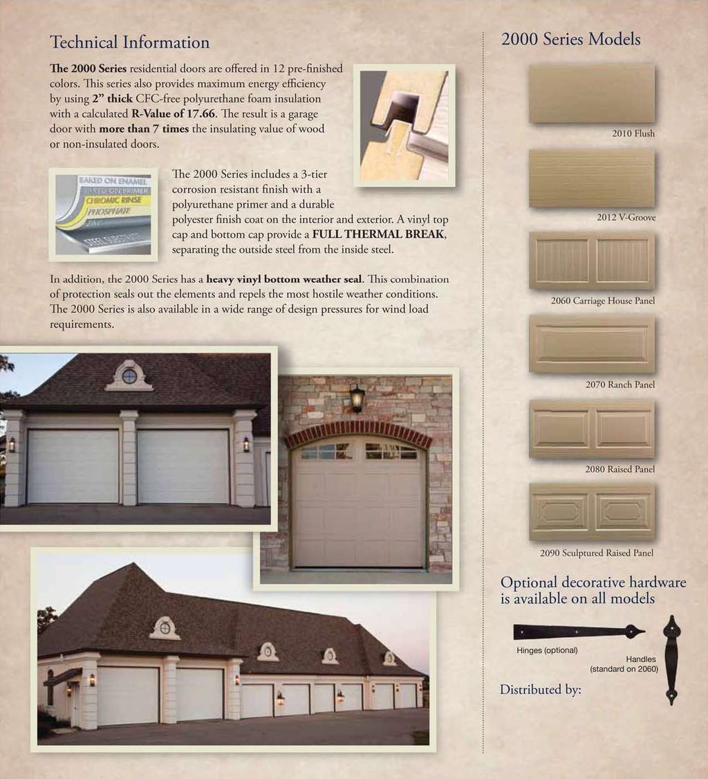
2
3


4 700 series The 700 Series I 710 I 712 I 760 I 770 I 780I 790 The 700 Series is our premier line of garage doors. The 700 Series offers the look of deep embossed wood grain with the strength and durability of heavy gauge galvanized steel. The 700 Series boasts one of the highest energy ratings of any garage door in the industry, insulated for maximum energy efficiency and engineered for years of use. Backed by a Limited Lifetime Warranty, the 700 Series is ideal in all climates and offers a full range of color and window options. Adding beauty and value to your home has never been so easy! R Value 16.18


5 Technical Information The 700 Series is offered in 12 pre-finished colors. This series provides maximum energy efficiency with 1 3 /4" thick, CFC FREE, polyurethane insulation with a calculated R-Value of 16.18, resulting in doors that provide more than six times the insulating value of wood or non-insulated doors. The 700 series includes a three-tier, corrosion-resistant protective finish with a polyurethane primer and a durable polyester finish coat on the interior and exterior. A vinyl top cap and bottom cap provide a full-thermal break, separating the outside steel from the inside steel. Included is a heavy vinyl bottom weather seal. This combination of protection seals out the elements and repels the most hostile weather conditions. See our Window Option literature for all the window and glass options. The 700 Series is also available in a wide range of design pressures for wind load requirements. 700 Series Models 710 Flush 712 V-Groove 760 Carriage House 770 Ranch Panel 780 Raised Panel Optional decorative hardware is available on all models 790 Sculptured Raised Panel Distributed by: Hinges (optional) Handles (standard on 760)


6 600 series The 600 Series I 610 I 612 I 660 I 670 I 680I 690 The 600 Series offers the look of deep embossed wood grain with the strength and durability of heavy gauge galvanized steel. The 600 Series is urethane insulated for energy efficiency and engineered for years of virtually maintenance free use without the worry of warping, cracking, or rotting. Backed by a Limited Lifetime Warranty, the 600 Series is ideal in all climates and offers a full range of color and window options. Adding beauty and value to your home has never been so easy! R Value 13.45


7 Technical Information The 600 Series is offered in 12 pre-finished colors. This series provides maximum energy efficiency with 1 3 /8" thick, CFC FREE, polyurethane insulation with a calculated R-Value of 13.45, resulting in doors that provide more than five times the insulating value of wood or non-insulated doors. The 600 Series includes a three-tier, corrosion-resistant protective finish with a polyurethane primer and a durable polyester finish coat on the interior and exterior. A vinyl top cap and bottom cap provide a full-thermal break, separating the outside steel from the inside steel. Included is a heavy vinyl bottom weather seal. This combination of protection seals out the elements and repels the most hostile weather conditions. See our Window Option literature for all window and glass options. The 600 Series is available in a wide range of design pressures for wind load requirements. 600 Series Models 610 Flush 612 V-Groove 660 Carriage House 670 Ranch Panel 680 Raised Panel Optional decorative hardware is available on all models 690 Sculptured Raised Panel Distributed by: Hinges (optional) Handles (standard on 660)


8 INSTALLATION MANUAL and OWNERS MANUAL RESIDENTIAL STEEL DOORS 6-6, 7-0, 7-6 & and 5-Section High Doors Read Instructions Thoroughly Before Starting Installation Thank you for your purchase of a Haas Sectional door system. This system is designed to provide years of trouble free service with very little maintenance required. It is important that you thoroughly read these instructions before proceeding with the installation of the door system. Throughout the instructions you will see a stop sign next to instructions in bold type. It is important that you follow these important installation points before continuing. Once you have completed the installation of your door please keep the instructions for future reference. Thank you -IMPORTANT- Installation of the Sectional door and spring counterbalance system is to be performed by qualified sectional overhead garage door technician. The following instructions are intended for use by installers familiar with all aspects of sectional overhead garage doors who have a general understanding of garage door industry terminology. Thoroughly read the entire sectional door and counterbalance system instructions, BEFORE beginning the installation. Strict compliance to these instructions will insure an effective, safe, and efficient installation that provides years of trouble-free customer satisfaction. -IMPORTANT- WARNING TORSION AND EXTENSION SPRING ASSEMBLIES ARE UNDER EXTREME TENSION AT ALL TIMES AND CAN BE DANGEROUS.INSTALLATION, REMOVAL AND/OR ADJUSTMENTS TO A TORSION SPRING OR WEIGHT COUNTERBALANCE ASSEMBLY (INCLUDING ALL BEARING BRA CKETS, CABLES, DRUMS AND BOTTOM FIXTURES) SHOULD BE PERFORMED BY QUALIFIED GARAGE DOOR TECHNICIAN.
9 WARNING - IMPORTANT To protect yourself from injury, carefully read the following safety information and warnings before you install your new garage door or attempt to remove your old door. This symbol means WARNING / CAUTION. Personal injury and/or property damage may occur if instructions are not followed carefully. Please pay close attention to instructions following this symbol. - SAFETY INFORMATION You can install your new garage door yourself, if: 1. You have help (your garage door can weigh up 600 pounds.) 2. You have the right tools and reasonable mechanical aptitude or experience 3. You follow these instructions very carefully. This symbol means STOP! Unsatisfactory installation results and/or poor product performance may occur if instructions are not followed carefully. Please pay close attention to instructions following this symbol. -Torsion spring installations require center spring mounting pad(s). The mounting pads may be wood (2 x 6 x 12 minimum) that must be of good quality and firmly attached to a supporting structure using four (4) 3/8 X 3 lag screws. The wood used for the mounting pad should be made of Grade 2 or better Southern Yellow Pine (Southern Pine or Yellow Pine.) -Garage doors use springs to counterbalance them. There are two types of springs used extension springs and torsion springs. If your old door uses torsion springs, do not attempt to remove the door or the springs yourself. Have a qualified door repair service person remove them. Attempting to remove a torsion spring assembly without proper training or tools may result in an uncontrolled release of spring forces, which can cause serious or fatal injury. -When installing a door with torsion springs, always use solid steel winding bars. Winding bars are available from professional door installers. The use of screwdrivers or any substitutes for winding bars will risk severe injury. -The brackets at the bottom corners of your garage door are under great tension. Do not attempt to loosen any bracket fasteners. Otherwise, the bracket could fly out with dangerous force. -Keep hands and fingers clear of section joints, track, and other door parts when the door is opening and closing to avoid injury. The lift handle and/or pull rope should be used when opening or closing a non-powered door. -Extension spring doors must never be operated without properly installed spring containment cables. -Horizontal track installations must use sway braces on the rear of the track to prevent sideways movement. If the tracks are not properly anchored they might spread, allowing the door to fall and cause severe injury and damage. 2 Do not use wood labeled Spruce-Pine- Fir (SPF). If the pad is to be anchored to concrete use four 3/8 masonry anchors. If the wood mounting pad(s) splits during or after the torsion spring(s) are wound, it should be replaced by a professional installer. Do not attempt to remove or repair the mounting pad(s) once a spring is wound. - It is not recommended to install spring mounting pad(s), track, or sway braces through drywall. The drywall reduces the engagement area of the lag screws and reduces the strength of the door assembly. -Torsion springs, extension springs, cables, and bottom fixtures are under strong spring tension. Do not attempt to loosen any fasteners on these components. You could suddenly release the spring forces and risk severe injury. -Do not permit children to play beneath or around any garage door or electric operating controls. Tools Needed -(2) C-Clamps or Vise Grip Style Pliers -Hammer -Flat Head Screwdriver -Tape Measure -Carpenters Level -Ratchet Wrench and Socket Set including 7/16, 5/16, and 3/8 -Open End Wrench Set including 3/8 -Pliers -6 Step Ladder -Electric Drill with a good quality Drill Bit Set -Power Screw Gun/Driver Copyright 2005, Haas Door Company Rev.5/05
10 -Winding Bars Clear away all household items to make room. It is -Impact important to have adequate space to maneuver the door -6 extension sections and parts. Take time to see that all household items are cleared away and that nothing will hinder you when installing the new door. Before you begin the installation of your Haas Sectional Door, verification of proper materials and clearances required will insure a trouble-free installation. While performing this inspection: Hanger Kit -Check all materials with the packing slip found in the You may need to build track hangers, as these are not hardware carton. Any report of shortages must include a supplied with your standard door kit. You will need at least: copy of the packing slip. (6) six, 18 to 30 pieces of 1/8 x 1-1/2 punched angle. (4) four 5/16 x 1-1/2 lag screws to anchor them to the -Check the opening to ensure that it is plumb and square. trusses. This is essential for a good fit and proper installation. (8) eight of each: -Check the opening width (see Figure1) and verify that the 5/16 x ¾ hex-head bolts door is the proper size for the opening. Wood jambs require 5/16 lock washers the door size to be the same size as the framed opening with 5/16 nuts stop moldings nailed to the inside of the opening to seal the door. Haas Door Painting Instructions Any garage door surface to be repainted must be properly prepared to assure the continued performance of the coating system. The following instructions must be followed to ensure proper repainting results. 1. Dirt, loose chalk and mildew must be removed prior to repainting. Heavier dirt accumulations must be addressed prior to repainting by the use of a dilute solution of Spic and Span (1cup into 5 gallons of warm water). Always rinse the surface thoroughly to remove any of the cleaning agents. 2. Minor scratches, which have not left the metal substrate exposed, can be lightly sanded or buffed to create a smoother surface. Care must be taken, however, not to expose the substrate. Once this exposed metal condition exists, the likelihood of rusting is greatly increased. Should the metal substrate be observed during this operation, see the following paragraph (Do not use Steel Wool) 3. Exposed metal must be treated to prevent rust from forming. To do so, sand the general area lightly and use a primer specifically designed to protect any exposed galvanized steel metal from corrosion. Allow sufficient time for the primer to dry before applying the topcoat. If either red or white rust is evident, scrape or brush away as much rust as possible and then sand lightly, removing ALL rust before priming, care must be taken, however to, not to destroy the galvanized surface. 4. After the door has been properly prepared, it must be coated within 24 hours using high quality latex exterior house paint. The surface must be completely dry prior to paining. Painting should not be done in the early morning. Avoid painting at temperatures below 50F. Follow the paint manufacturer s recommendations to apply a uniform coat at the proper thickness. CAUTION: Use of paints containing linseed oil, lacquer or alkyd base solvents voids the warranty of this door. Preparation If door being installed is a designated Load garage door a 1 overlap is required. (Figure1) Rev. 5/05 Copyright 2005, Haas Door Company 3 Wind (Figure 2) - Check for adequate side room available (see Figure 1). The door system requires 3 ¾ (95.25mm) for 2 track. - Check for adequate headroom available (see Figure 1). The door system requires: Headroom Required* 12 Radius Torsion 11.5 (280mm) 15 Radius Torsion 15.5 (356mm) 12 Radius Extension 6 (254mm) 15 Radius Extension 6 (356mm) Low Head room Rear Torsion 3 (102mm) Low Headroom Front Torsion 10 (204mm) Low Headroom Extension 6 (102mm)
11 *Electric operators require additional headroom. See Once you have verified all of the basic installation instructions provided with operator for exact amount. requirements, you can start the installation. 4 Copyright 2005, Haas Door Company Rev.5/05
12 STEP 1 First find the bottom section. (The bottom section has a rubber weather seal attached to its bottom edge with small screws.) Place the bottom section onto a clean smooth nonabrasive work surface. If using saw horses as a work surface, with sections over 10ft long you must use at least four saw horses to support the section. Cover the sawhorses with cloth or cardboard to protect the door from scratching. Attach the bottom corner brackets using ¼ x ¾ long self-drilling screws (see Figure 3) to both ends of the door section. (For rear mount low headroom see Figure 3R). Then attach #1 hinges, also using ¼ x ¾ long self-drilling screws, to each stile location on the top of the section (see Figure 4, for hinge identification). INSTALLING THE NEW DOOR STEP 2 If door being installed is a designated Wind Load garage door refer to the included Wind Load Supplemental Instruction booklet for special instructions. First look at Table 1 to see if your door is requires struts. If no U-Bars are required then go one to Step 3. If your door requires U-Bar(s) they are to be fastened using (2) ¼ x ¾ long self-drilling screws per stile location. -If your door requires one U-Bar it will be installed on the top section just above the top corner bracket on STEP 10 -If your door requires three U-bars the first U-Bar should be installed now on the bottom section just below the top hinges on the section as shown (see Figure 5). It should be located just below the top hinges on the section as shown (see Figure 5). The second U-Bar will be installed on the second section for a four section high door and the third section for a five section high door. The third U-Bar will be installed on the top section just above the top corner bracket on the last section. For ease of installment it is best to attach the struts right before placing the section in the opening. (Figure 3) (Figure 3R) (Figure 4) *Hinges also stamped with number (Figure 5) Residential Garage Door Strut Schedule Model Color 14'-0" 15'-0" 16'-0" 17'-0" 18'-0" All RHT White, Gray, No 1, 2" 1, 2" 3, 2" 3, 2" & RMT Almond, Strut per per per per All RHT & RMT 248, 248L 258, 258L Sandstone Door Door Door Door Brown, 3, 2" 3, 2" 3, 2" 3, 2" 3, 2" Hunter per per per per per Green Door Door Door Door Door White, No 1, 2" 1, 2" 3, 2" 3, 2" Brown, Strut per per per per Almond, Door Door Door Door Sandstone White, No 1, 2" 1, 2" 3, 2" 3, 2" Brown, Strut per per per per Almond, Door Door Door Door Sandstone (Table 1) Rev. 5/05 Copyright 2005, Haas Door Company 5
13 STEP 3 Position the bottom section by centering the section in the opening. Level the door section in the opening, using shims if necessary (see Figure 6). Once the section is level, insert the rollers into the bottom brackets and the #1 hinges on each end of the section. STEP 4 (Figure 6) (Figure 7) STEP 5 Position the right hand track over the rollers as shown (see Figure 8). Space the vertical track ½ from door as shown. Before attaching the vertical track/angle or brackets to the doorjambs, be sure that the vertical track/angle or brackets are plumb and parallel to the door section. If door being installed is a designated Wind Load garage door refer to the included Wind Load Supplemental Instruction booklet for special instructions. If jamb brackets are already attached to track continue on to Step 5 if not continue. Begin by laying out the parts for each vertical track. Attach the two jamb brackets to the vertical track (see Figure 7) using ¼ slotted track bolts and ¼ flange nuts. Compare each mounting bracket for size, as one is slightly longer than the other. They are stamped with a number 4 or number 5 (#1 & #3 for 1-3/8 door and #4  for a 1-3/4 door). The number 4 bracket is shorter and it is mounted towards the bottom end of the vertical track about 5 from the end. Next attach the number 5 bracket to the track at approximately the center of the track. (For 8 high doors you will also attach a number 6 bracket to the track above the number 5 bracket) Attach the upper flag brackets to the upper end of the vertical track using two ¼ slotted track bolts and two ¼ flange nuts. Repeat this process again for the right hand vertical track assembly. (Figure 8) Attach the vertical track brackets to the doorjambs by using 5/16 x 1-1/2 hex head lag screws on wood jambs. It is not recommended to install lag screws through drywall into wood jamb. If mounting directly to masonry, concrete anchors must be used (supplied by installer). Repeat process for the left hand track. Both tracks must be plumb and parallel each other for proper operation of door! STEP 6 Locate the #2 section and attach # 1 hinges to each intermediate stile location using two (2) ¼ x ¾ long selfdrilling screws. Attach a U-Bar if instructed to do so in to 6 Copyright 2005, Haas Door Company Rev.5/05
14 STEP 2. Place the section into the opening on top of the bottom section. Attach the # 2 hinges and rollers onto both ends of the section. Do this by first inserting the roller into the end hinge. Then hook rollers into vertical track and swing end hinge into door section. Then fasten hinges from section below using two (2) ¼ x ¾ long self-drilling screws (see F igure 9). (Figure 9) If door being installed is a designated Wind Load garage door make sure there is at least a 1 overlap on each side between the end of the door and the jamb. Locate the #3 section and attach # 1 hinges to each intermediate stile location using two (2) ¼ x ¾ long selfdrilling screws. Attach a U-Bar if instructed to do so in STEP 2. Place the section into the opening on top of the #2 section. Attach the #3 hinges and rollers onto both ends of the section. Do this the same way the #2 hinges were installed (see F igure 9). Fasten hinges from section below using two (2) ¼ x ¾ long self-drilling screws. If installing a five section high door, you will attach a #4 hinge to the top of the fourth section. STEP 7 The inside slide lock or cylinder lock is installed in the #2 (second) section. The slide lock can be installed at either end of the section. The slide bar of the lock should rest against the top of one of the rectangular slots in the vertical track (for slide lock, see Figure 10) (for cylinder lock, see Figure 11) (for snap latch lock, see instructions enclosed with lock kit). (Figure 11) (Figure 10) (Figure 12) STEP 8 If installing a torsion spring door, attach the end bearing brackets to the horizontal angles using 5/16 x ¾ bolts & nuts. If installing an extension spring door or rear mount double track installation of the end bearings is not required at this time. Form rope loops and attach them to a convenient overhead structural member. Insert the rear of the tracks through the loops to support the tracks during installation. Attach the bottom of the track radius to the flag brackets and fasten them using ¼ x 5/8 truss head track bolts. The heads of the track bolts should be on the inside of the track (see Figure 12). Attach the horizontal angle to the vertical track angle using a 5/16 x ¾ bolt & nut. Attach the end-bearing bracket to the Rev. 5/05 Copyright 2005, Haas Door Company 7
15 side jamb using 5/16 x 1-1/2 hex head lag screws on wood jambs. It is not recommended to install lag screws through drywall into wood jamb. If mounting directly to masonry, concrete anchors must be used (supplied by installer). Repeat process for the right hand track. STEP 9 Replace the temporary rope support hangers with steel support angles (supplied by installer) (see Figure 13). Install sway braces after checking the horizontal track with a tape measure to verify that they are parallel to each other and square to the door sections. The support hangers for rear mount torsion installations must be a minimum of 2"x2 x1/8 black iron angle. The steel supports must be strong enough to (Figure 13) support the full door weight, and must be attached to a structurally sound member! At this point your sectional door should be in the opening. The next step will be installing the counterbalance assembly. You will first have to locate your springs and determine what kind of springs were provided with your sectional door. For torsion springs installation proceed to STEP 10-T on page 8, For extension spring installation proceed to STEP 10-E on page 11 For rear torsion mo unt double track installati on proceed to STEP 10-R on page 13 WARNING TORSION AND EXTENSION SPRING ASSEMBL IES WILL BE UNDER EXTREME TENSION AND CAN BE DANGEROUS. INSTALLATION AND/OR ADJUSTMENTS TO A TORSION SPRING OR WEIGHT COUNTERBALANCE ASSEMBLY (INCLUDING ALL BEARING BRACKETS, CABLES, DRUMS AND BOTTOM FIXTURES) SHOULD BE PERFORMED BY QUALIFIED GARAGE DOOR TECHNICIAN. WARNING 8 Copyright 2005, Haas Door Company Rev.5/05

16 STEP 10-T TORSION SPRING INSTALLATION Place the top section into position. Insert rollers into the adjustable slide on the top corner brackets. Measure down 3-1/4 from the top of the section and mark the position. Attach the brackets onto the top section with the top of the brackets at the 3-1/4 mark using two (2) ¼ x ¾ long self-drilling screw, one at the top and one at the bottom of the bracket. (See Figure 14T) (Figure 16T) See Figure 17T for spring orientation. The components should be laid out as shown while facing the door from the inside of the opening (inside-facing-out). (Figure 14T) Adjust the bracket slide so the top section is perfectly vertical and tighten adjusting bolts securely. Attach the top leaves of the hinges from the preceding section using two (2) ¼ x ¾ long self-drilling screws. Attach a U-Bar if instructed to do so in STEP 2. STEP 11-T Locate the cable drums, torsion spring(s), center bearing bracket, center bearing and tubular shaft. (The spring(s) should be pre-mounted over the tubular shaft). Lay all of the parts out on the floor for double wide doors, see Figure 15T, for single wide doors, see Figure 16T. (Figure 17T) Slide the center shaft support bearing/bracket, torsion spring(s) and cable pickup drums onto the shaft prior to lifting the shaft in place (see Figure 15T). The right hand (black) cable drum is to be placed on the right hand side of the opening (inside looking out) and the left hand (red) cable drum is mounted on the opposite side. The cable drum set screws should be facing towards the center of the opening. Hand tighten all the set screws on the springs and drums to prevent them from sliding off when you lift the shaft assembly into place. Do not fully tighten the setscrews at this time. Next lift the shaft assembly into place and slide the shaft through the bearing on the left end-bearing bracket and then over to the right and through the right end bearing bracket. (see Figure 18T) Support the shaft assembly while lifting into place: failure to do so my result in bending due to the weight of the springs and bearing plate. (Figure 15T) (Figure 18T) Rev. 5/05 Copyright 2005, Haas Door Company 9
17 (Figure 21T) Ensure that the shaft assembly is level at all points before continuing. After inserting the shaft assembly, securely anchor the center shaft support bracket(s) to the mounting pad (see Figure 19T) using two (2) 5/6 X 1-3/4 lag screws. STEP 12-T (Figure 19T) Attach the lift cables to the bottom brackets (see Figure 20T). Attach the cable loop end to the cable button on the left hand bottom bracket. Ensure that the cables are wrapped correctly onto the first cable groove of the drums. Rotate the cable drum so that the slack is pulled out of the cable; position the end of the shaft to allow for the correct amount of shaft extension beyond the end-bearing bracket. Slide the cable drum over to the left so that it is snug against the bearing on the end-bearing bracket. Tighten down the setscrews on the left hand cable drum. While holding tension on the left hand cable, attach a pair of vise grips onto the torsion shaft and against the header to hold tension (see Figure 22T). Repeat the process attaching the right hand cable to the right hand bottom corner bracket and to the right hand cable drum. Using the vise grips on the shaft, rotate lightly counterclockwise to tension the cables. While holding this position, attach another pair of vise grips to the shaft with the end against the wall in a manner that will prevent the shaft from rotating clock-wise. Light, even tension is adequate. (Figure 20T) Lead the cable up along side the door (between the door and the vertical track) up to the left hand cable drum. Wrap the cable up from behind the drum and over and insert the end through the cable entry s lot on the drum (see Figure 21T). (Figure 22T) Ensure that the cables are equally tensioned before continuing. Note: Leave the vise grips in place on the torsion shaft after you have finished installing both cables. Do not remove them until after you have wound the torsion spring(s). STEP 13-T You are now ready to wind the torsion springs. You will need a pair of winding bars. The winding bars must be made from ½ diameter cold rolled steel and must be at least 18 long. These are not furnished with your door but are available at most hardware stores. WARNING: NO OTHER SUBSTITUTE TOOL CAN BE USED. 10 Copyright 2005, Haas Door Company Rev.5/05
18 The vise grips should still be on the torsion shaft and wedged Locate the tag attached to each spring, noting the number of against the header to prevent the shaft from turning. If you turns that the spring requires. You will need to wind the have removed the vise grips from the shaft and the cables have spring according to this tag information. Next insert the become loose YOU MUST RE-TIGHTEN AND SET second bar in the hole of the winding cone and while holding BOTH CABLES PROPERLY ON THE DRUMS it firmly with a little back pressure (see Figure 24T), remove BEFORE PROCEEDING! the upper winding bar and turn (wind) the spring up another ¼ turn. Repeat this step-by-step procedure until the spring has been wound the proper number of turns. WARNING: NEVER STAND DIRECTLY While holding the winding bar, carefully tighten the two IN FRONT OF THE WINDING BARS OR setscrews on the torsion spring winding cone. The setscrews ALLOW ANYONE TOSTAND INLINE WITH THE should be tightened four (4) full additional turns after they WINDING BARS WHILE WINDING OR ADJUSTING have made initial contact with the torsion shaft. SPRINGS. If your door has two springs, repeat the same procedure using Start winding the spring by drawing a chalk line horizontally the same extreme caution. across th e spring(s). This will help you to keep track of the number of turns you have wound the spring(s). A turn means one complete revolution of the winding cone. Now place the first winding bar in place, and hold firmly, CAREF ULLY start to wind the spring in an UPWARD direction (see Figure 23T). (Figure 24T) After the spring(s) have been wound and the setscrews have been securely tightened r emove the vise grips. (Figure 23T) DANGER: ALWAYS MAINTAIN CONTROL OF THE WINDING BARS BY KEEPING STEADY PRESSURE ON THE WINDING CONE AT ALL TIMES. DANGER: As you lift the door for the first time, make sure that the top track rollers do not slip out of the horizontal tracks. (The track may spread if it has not been properly aligned). Do not stand beneath or under the door. Try opening and closing the door. The effort to open and close the door should be the same. If the door seems heavy when you open it, but easy to close, you need to wind the spring an additional ¼ turn. If the door is very easy to open (will not stay on the floor) and is hard to close, you will need to unwind the springs ¼ turn. Do this following the same instructions in this step (step 12-T). Rev. 5/05 Copyright 2005, Haas Door Company 11
19 EXTENSION SPRING INSTALLATION STEP 10-E Place the top section into position. Insert rollers into the adjustable slide on the top corner brackets. Measure down 3-1/4 from the top of the section and mark the position. Attach the brackets onto the top section with the top of the brackets at the 3-1/4 mark using two (2) ¼ x ¾ long self-drilling screw, one at the top and one at the bottom of the bracket. ( See Figure 14E) Attach the two- (2) sheave straps to the two (2) cable sheaves using 3/8 x 1-1/2 hex head bolts and nuts (see Figure 16E). (Figure 16E) Loop the end of extension spring through the sheave strap. Then attach the other end of the spring to the rear track hanger about 4 to 6 above the horizontal track using 2 eyebolts (see Figure 16E). Make sure that the eyebolt hook is pointed up to prevent the spring from slipping off. Place the loop ends of the lifting cables over the cable stud on the bottom corner brackets as shown (see Figure 17E). (Figure 14E) Adjust the bracket slide so the top section is perfectly vertical and tighten adjusting bolts securely. Attach the top leaves of the hinges from the preceding section using two (2) ¼ x ¾ long self-drilling screws. Attach a U-Bar if instructed to do so in STEP 2. STEP 11-E Carefully lift the door up to the full open position, clamp the door in place using large C-clamps or large vise-grips attached to the curved portion of the horizontal tracks. You should have one or more helpers to assist you when lifting the door! Attach the cable sheaves to both of the horizontal angles as shown, approximately 4 from the doorjamb, using the 3/8 x 1-1/2 long hex head bolts and nuts (see Figure 15E). (Figure 16E) 12 (Figure 17E) Lead the cable up along side the door (between the door and the vertical track) up to cable sheave. Thread the cable back to, and around the spring cable sheave and back towards the door. (See Figure 89E and 19E). Tie the cable to the cable-anchor clip exactly as shown and then place an s -hook in the end of the clip (see Figure 20E). Pull the (Figure 15E) cable taut so it stretches the spring(s) about 1 and attach the cable to the horizontal angle with the s -hook. Copyright 2005, Haas Door Company Rev.5/05
20 DANGER: Spring containment cables Must be installed for safe operation of the door. Thread the containment cable through the entire length of the extension spring. First fasten the cable to the door jamb, using the 3-hole clip and the ¾ lag bolts that mount the flag bracket to the door jamb (see Figure 21E). (Figure 18E) (Figure 19E) (Figure 21E) Thread the cable through the center hole of the clip and then back through the top hole of the clip. Complete the threading by inserting the end between the clip and the cable on the backside. Attach the other end of the cable to the track hanger (see Figure 22E). Do not pull the cable taut; allow enough slack in the cable to allow the spring to slid easily over the cable without pinching the cable when the door is raised. (Figure 20E) DANGER: The cable must be tied to the cable clip exactly as shown to prevent the cable from slipping. Weave any excess cable throug h the holes in the horizontal angle. Repeat this process for the other side cable and spring. Make sure that both springs are equally tensioned before continuing. Unequal spring tension will cause the door to bind during operation. STEP 12-E When the door is down, the extension springs are under extreme tension and could cause damage or severe injury should any fasteners or components fail. For this reason a spring containment cable is required for each spring. (Figure 22E) Repeat the process for the opposite spring. Double check that all fasteners are tight before releasing the C-clamps (or vise grips) and testing the door movement. Lower and raise the door and check for smooth operation. If the door comes down too fast or hits hard, you will need to increase the spring tension. Do this by raising the door and clamping it into place as before. Then pull the spring tighter by moving the s -hook one or two holes (on the horizontal angle) closer to the doorjambs. If the door comes down slowly or not all the way down, you will need to decrease the spring tension, do this by raising the door and clamping it into place as before. Then loosen the springs by moving the s -hook one or two holes (on the horizontal angle) further away from the doorjambs. You can fine-tune the door by adjusting the eye-bolt in or out on the track hanger. Rev. 5/05 Copyright 2005, Haas Door Company 13
21 drum set screws should be facing out from the center of the Rotate the cable drum so that the slack is pulled out of the opening. Adjust the cable drums so they are against the cable. Position the end of the shaft to allow for the correct bearings in the bearing brackets. Lightly tighten the drums to amount of shaft extension beyond the end-bearing bracket. hold them in place. Do not fully tighten the setscrews at this Slide the cable drum so that it is snug against the bearing on time. the end-bearing bracket. Tighten down the setscrews on the left hand cable drum. While holding tension on the left hand cable, attach a pair of vise grips onto the torsion shaft and against the end of the horizontal track to hold tension. Repeat the process attaching the right hand cable to the right hand bottom corner bracket and to the right hand cable drum. Using the vise grips on the shaft, rotate lightly counterclockwise to tension the cables. While holding this position, attach another pair of vise grips to the shaft with the end against the track in a manner that will prevent the shaft from rotating clock-wise. Light, even tension is adequate. STEP 13-R (Figure 19R) Attach the lift cables to the bottom brackets (see Figure 20R). Insert the cable pin through the bottom bracket and cable loop end and insert the cotter pin through the cable pin end. Crimp over the cotter pin and repeat process for other cable assembly. Ensure that the cables are equally tensioned and are wrapped correctly onto the first cable groove of the drums before continuing. Note: Leave the vise grips in place on the torsion shaft after you have finished installing both cables. Do not remove them until after you have wound the torsion spring(s). STEP 15-R You are now ready to wind the torsion springs. You will need a pair of winding bars. The winding bars must be made from ½ diameter cold rolled steel and must be at least 18 long. These are not furnished with your door but are available at most hardware stores. (Figure 20R) STEP 14-R Lead the cable up along side the door (outside of the door) up to the left hand cable drum. Wrap the cable up from behind and over the sheave and back to the drum. Wrap the cable from underneath the drum and insert the end through the cable entry slot on the drum (see Figure21R). WARNING: NO OTHER SUBSTITUTE TOOL CAN BE USED. The vise grips should still be on the torsion shaft and wedged against the track to prevent the shaft from turning. If you have removed the vise grips from the shaft and the cables have become loose, YOU MUST RE-TIGHTEN AND SET BOTH CABLES PROPERLY ON THE DRUMS BEFORE PROCEEDING! WARNING: NEVER STAND DIRECTLY IN FRONT OF THE WINDING BARS OR ALLOW ANYONE TO STAND INLINE WITH THE WINDING BARS WHILE WINDING OR ADJUSTING SPRINGS. Start winding the spring by drawing a chalk line horizontally across the spring(s). This will help you keep track of the number of turns you have wound the spring(s). Now place the first winding bar in place, and hold firmly, CAREFULLY start to wind the spring in a DOWNWARD direction (see Figure 22R). (Figure 21R) Rev. 5/05 Copyright 2005, Haas Door Company 15
22 REAR TORSION MOUNT DOUBLE FRONT MOUNT TRACK INSTALLATION STEP 10-R Insert a roller into the top corner bracket and attach to each end of the top section as shown, using two (2) ¼ x ¾ self drilling screws (see Figure 14R). The track roller should be inserted into the upper horizontal track as shown. Attach a cable sheave to each horizontal track angle (see Figure 15R) using 3/8 x 1-1/2 hex head bolt, 3/8 washer and nut. (Figure 16R) (Figure 14R) (Figure 17R) STEP 11-R (Figure 15R) Locate the cable drums, torsion spring(s), center bearing bracket, center bearing and torsion shaft. The spring(s) should be pre-mounted over the shaft). Lay all of the parts out on the floor (for double wide doors, see Figure 16R) (for single wide doors, see Figure 17R) exactly as shown. See Figure 18R for spring orientation. The components should be laid out as shown while facing the door from the inside of the opening (inside-facing-out). (Figure 18R) Slide the center shaft support bearing/bracket and torsion spring(s) onto the shaft. Tighten the setscrews on the spring fitting just enough to hold them in place while lifting the assembly. (Leave cable pickup drums off for now). STEP 12-R Install the rear mounted bearing plates. Next lift the shaft assembly into place and slide the shaft through the bearing on the left end-bearing bracket and then over to the right and through the right end bearing bracket (see Figure 19R). Support the shaft assembly while lifting into place. The shaft can be damaged by bending due to the weight of the springs and center bearing plate. The right hand (black) cable drum is to be placed on the right hand side of the opening (inside looking out) and the left hand (red) cable drum is mounted on the opposite side. The cable 14 Copyright 2005, Haas Door Company Rev.5/05
23 (Figure 22R) DANGER: ALWAYS MAINTAIN CONTROL OF THE WINDING BARS BY KEEPING STEADY PRESSURE ON THE WINDING CONE AT ALL TIMES. Locate the tag attached to each spring, noting the number of turns that the spring requires. You will need to wind the spring according to this tag information. Next insert the second bar in the hole of the winding cone and while holding it firmly with a little back pressure (see Figure 23R), remove the upper winding bar and turn (wind) the spring up another ¼ turn. Repeat this step-by-step procedure until the spring has been wound the proper number of turns. While holding the winding bar, carefully tighten the two setscrews on the torsion spring winding cone. The setscrews should be tightened four (4) full additional turns after they have made initial contact with the torsion shaft. (Figure 23R) After the spring(s) have been wound and the setscrews have been securely tightened remove the vise grips. DANGER: As you lift the door for the first time, make sure that the top track rollers do not slip out of the horizontal tracks. (The track may spread if it has not been properly aligned). Do not stand beneath or under the door. Try opening and closing the door. The effort to open and close the door should be the same. If the door seems heavy when you open it, but easy to close, you need to wind the spring an additional ¼ turn. If the door is very easy to open (will not stay on the floor) and is hard to close, you will need to unwind the springs ¼ turn. Do this following the same instructions in this step (Step 15-R). 16 Copyright 2005, Haas Door Company Rev.5/05
24 Maintenance Routine maintenance one annually will help assure long lasting, quiet, trouble free operations of your Haas Sectional Door. Visual Inspection Look at the garage door springs, cables, rollers, pulleys and other door hardware. If you suspect problems, have a qualified person make repairs. WARNING: Springs are under high tension. Only qualified persons should adjust them. Cleaning Dirt and mildew must be removed to maintain desired appearance. Use mild houses hold cleaner and wipe down surface of the door. Rinse surface thoroughly to remove any cleaning agent. Lubricate Lubrication should be done with silicone grease. Lubricate all moving parts of the door including hinges, springs, steel rollers and lift cables. However, do not lubricate plastic parts such as plastic rollers. Rev. 5/05 Copyright 2005, Haas Door Company 17


25 600, 700 & 2000 Series STEEL RESIDENTIAL GARAGE DOORS Haas Door Company warrants its residential RMT-600, RHT-700, & RHT-2000 series steel garage door sections to be free from delamination or rust-through for so long as the original residential purchaser owns the building where the door sections are installed. All other components are warranted to be free from defects in workmanship and material for a period of one (1) year from date of installation. This Limited Lifetime Warranty applies only to steel garage door sections manufactured by Haas Door Company and components manufactured or supplied by Haas Door Company. The warranty excludes: (1) Sections and/or component parts which have been damaged due to misuse; (2) Sections and/or components which have been improperly installed, maintained or operated; (3) Sections and/or components that have been damaged due to accident; (4) Sections and/or components that have been damaged due to exposure to corrosive fumes/chemicals, alkaline cleaning agents, condensation or fire; (5) Performance of coatings used to finish the garage door sections; (6) Repair and/or replacement labor charges, including travel cost; (7) Damages resulting from other causes beyond the manufacturers control. In the event any defect is claimed during the warranty periods, a claim in writing must be submitted to Haas Door Company, directed through an authorized Haas Door Company dealer or installer. This claim must be submitted within fifteen (15) days of the discovery of the suspected defect. The door and all components must be available for inspection by an authorized Haas Door Company representative. Upon verification of a manufacturing defect, Haas Door Company will provide repair or replacement part(s) at its option. THE MANUFACTURER SHALL NOT BE RESPONSIBLE FOR ANY INCIDENTAL OR CONSEQUENTIAL DAMAGES ARISING OUT OF ANY BREACH OF THIS EXPRESS LIMITED WARRANTY, including but not limited to any damage to buildings, other property or for any injuries or damages sustained by any person whomsoever, or the recovery of any direct or indirect costs such as shipping, travel, lost time, installation labor charges, paint or painting, cleaning, repair, or other building materials. This warranty gives you specific legal rights and you may also have other rights that may vary from state to state. Haas Door Company does not authorize anyone to change or modify the above warranties in any respect. ANY IMPLIED WARRANTY OR MERCHANTABILITY OR FITNESS FOR A PARTICULAR PURPOSE APPLICABLE TO THE RESIDENTIAL MODEL(S) OF INSULATED STEEL OVERHEAD GARAGE DOORS IS LIMITED IN DURATION TO THE DURATION OF THE HAAS DOOR COMPANY WRITTEN WARRANTY SET FORTH ABOVE AND NEITHER HAAS DOOR COMPANY NOR ANY AUTHORIZED SELLING DEALER SHALL BE LIABLE FOR LOSS OF TIME, INCONVENIENCE, COMMERCIAL LOSS, OR OTHER CONSEQUENTIAL OR INCIDENTAL DAMAGES. Some states do not allow limitations on how long an implied warranty will last or the exclusion or limitation of incidental or consequential damages, particularly in consumer transactions, so the above limitations, or exclusions may not apply to you THIS WARRANTY IS NOT TRANSFERABLE Haas Door Company Effective: March 1, 2005 Revised: February 16, 2011
FOR PROFESSIONAL GARAGE DOOR INSTALLERS
 Composite Garage Doors Installation Instructions FOR PROFESSIONAL GARAGE DOOR INSTALLERS Tools required Screwdriver Claw Hammer Locking Pliers Power Drill Level with a 3/32" Drill Bit Utility Knife 9/16",
RESIDENTIAL GARAGE DOOR INSTALLATION INSTRUCTIONS UNITED
 RESIDENTIAL GARAGE DOOR INSTALLATION INSTRUCTIONS UNITED THIS GENERAL INSTRUCTION MANUAL IS INTENDED FOR THE INSTALLATION OF RESIDENTIAL GARAGE DOORS AND GENERAL INFORMATION FOR COMMERCIAL DOORS. DOORS
INSTALLATION TORSION SPRING FRONT OR REAR MOUNT LOW HEADROOM. 1 Cutting Vertical Track. 2 Fully Adjustable Jamb Brackets
 TORSION SPRING FRONT OR REAR MOUNT LOW HEADROOM Wayne Dalton, a division of Overhead Door Corporation P.O. Box 67, Mt. Hope, OH., 44660 Supplemental insert Copyright 2015 Wayne Dalton, a division of Part
Model Series T o r s i o n
 Model Series 7100 T o r s i o n Residential and Light Commercial Rear Mount Low Headroom Outside Hookup Table Of Contents Pre-Installation 2 Important Safety Instructions 2 Removing an Existing Door and
Rolling Curtain door Manual
 Rolling Curtain door Manual Installation Maintenance parts Model 944 PHONE 800 448 8979 FAX 800 236 8722 website www.tracrite.com EMAIL tr@tracrite.com ADDRESS 216 Wilburn Road Sun Prairie, WI 53590 This
GARAGE DOOR WITH TORSION SPRING
 GARAGE DOOR WITH TORSION SPRING DIMENSIONS 9 WIDTH X 7 HEIGHT (2.74m x 2.13m) IMPORTANT SAFETY INSTRUCTIONS WARNING: Read all instructions and warnings before use. Failure to follow all instructions may
Low Headroom Rear Mount TorqueMaster
 Low Headroom Rear Mount Supplemental Instruction Insert This supplemental installation instruction is to be used as a supplement to the main Installation Instruction and Owner s Manual provided with the
Models 9100 / 9405 / 9600
 Models 9100 / 9405 / 9600 T o r s i o n, S t a n d a r d L i f t Residential and Light Commercial Installation Instructions And Owner s Manual DEFINITION OF LIGHT COMMERCIAL: 1. Door heights less than
Models 105, 110, 106, 116, 310, 311, 314 and 316
 Models 105, 110, 106, 116, 310, 311, 314 and 316 T o r s i o n Residential and Light Commercial Standard Lift Installation Instructions And Owner s Manual DEFINITION OF LIGHT COMMERCIAL: 1. Door Heights
7100 Series. Standard Lift IMPORTANT NOTICES!
 GARAGE DOORS & OPENERS 7100 Series T o r s i o n Standard Lift PO installation instructions and owner s manual T a b l e O f C o n t e n t s Parts Breakdown 2 Pre-Installation 3 Important Safety Instructions
Models 42 and 45, Flush
 Models 42 and 45, Flush E x t e n s i o n Residential Standard Lift Installation Instructions And Owner s Manual Table Of Contents Pre-Installation 2 Important Safety Instructions 2 Removing an Existing
Models 8000 / 8100 / 8200
 Models 8000 / 8100 / 8200 T o r s i o n, C u t D o w n Residential and Light Commercial Installation Instructions And Owner s Manual Table Of Contents Pre-Installation 2 Important Safety Instructions 2
Model 44, Double Flush
 Model 44, Double Flush T o r s i o n, R e a r M o u n t L o w H e a d r o o m Residential and Light Commercial Quick Start Guide Table Of Contents Pre-Installation 2 Important Safety Instructions 2 Door
Standard Lift IMPORTANT NOTICES!
 GARAGE DOORS & OPENERS 6100 T o r s i o n Standard Lift MH installation instructions and owner s manual T a b l e O f C o n t e n t s Parts Breakdown 2 Pre-Installation 3 Important Safety Instructions
Model 7100 Series. T o r s i o n, R e a r M o u n t L o w H e a d r o o m
 Model 7100 Series T o r s i o n, R e a r M o u n t L o w H e a d r o o m Residential and Light Commercial Quick Start Guide Table Of Contents Pre-Installation 2 Important Safety Instructions 2 Door Section
Double Flush, Model 44
 Double Flush, Model 44 T o r s i o n Rear Mount Low Headroom MH Installation Instructions And Owner s Manual PLEASE DO NOT RETURN THIS PRODUCT TO THE STORE Please Do Not Return This Product To The Store.
Models 42 and 45. T o r s i o n, R e a r M o u n t L o w H e a d r o o m
 Models 42 and 45 T o r s i o n, R e a r M o u n t L o w H e a d r o o m Residential and Light Commercial Installation Instructions And Owner s Manual DEFINITION OF LIGHT COMMERCIAL: 1. Door Heights less
Important Notice. caution: Use proper lifting equipment and correct procedures to avoid injury.
 Integrity. Partnership. Quality. COMMERCIAL DOOR INSTALLATION INSTRUCTIONS SERIES 1900, 1950, 2000, 2250, 2500, 2750 Important Notice In the following text, the word: Warning: Indicates that serious injury
Model 7100 Series. T o r s i o n, R e a r M o u n t L o w H e a d r o o m
 Model 7100 Series T o r s i o n, R e a r M o u n t L o w H e a d r o o m Residential and Light Commercial Installation Instructions And Owner s Manual DEFINITION OF LIGHT COMMERCIAL: 1. Door Heights less
Spring Loaded All Season Roll-Up Doors
 Spring Loaded All Season Roll-Up Doors STAND-OFF MOUNTING METHOD INSTALLATION INSTRUCTIONS READ THIS FIRST Carefully examine the crate(s) for damage before opening. If the carton is damaged, immediately
Ultimate Products, Inc.? 2319 Laurelbrook Street? Raleigh, NC 27604? USA Toll-Free: (800) ? Fax: (919)
 ? Fax: (919)") Illuminator Door Installation & Maintenance Guide Ultimate Products, Inc.? 2319 Laurelbrook Street? Raleigh, NC 27604? USA Toll-Free: (800) 542-7221? Fax: (919) 834-4526 www.ultimate-product.com Table
Illuminator Door Installation & Maintenance Guide Ultimate Products, Inc.? 2319 Laurelbrook Street? Raleigh, NC 27604? USA Toll-Free: (800) 542-7221? Fax: (919) 834-4526 www.ultimate-product.com Table
Models 8300 / T o r s i o n. Windload
 Models 8300 / 8500 T o r s i o n Residential and Light Commercial Standard Lift Windload Table Of Contents Pre-Installation 2 Important Safety Instructions 2 Removing an Existing Door and Preparing the
Stop! Read This Important Information.
 Stop! Read This Important Information. Stop, Do Not Proceed, Read This This door replacement kit is designed for the replacement of doors on a Supertop ONLY! This door will not work on any other style
Model 44, Double Flush
 Model 44, Double Flush T o r s i o n, S t a n d a r d L i f t Residential and Light Commercial Installation Instructions And Owner s Manual DEFINITION OF LIGHT COMMERCIAL: 1. Door Heights less than or
Spring Loaded SCREEN-PRO. All Season Roll-Up Doors IN-JAMB MOUNTING METHOD INSTALLATION INSTRUCTIONS READ THIS FIRST
 Spring Loaded SCREEN-PRO All Season Roll-Up Doors IN-JAMB MOUNTING METHOD INSTALLATION INSTRUCTIONS READ THIS FIRST Carefully examine the crate(s) for damage before opening. If the carton is damaged, immediately
INSTALL INSTRUCTIONS WELCOME TO THE NEWAGE PERFORMANCE CABINETRY SERIES NEWAGE STEEL WELDED CABINETRY
 NEWAGE STEEL WELDED CABINETRY WELCOME TO THE NEWAGE PERFORMANCE CABINETRY SERIES ALL CABINETS MUST BE MOUNTED TO STUDS ON A SECURE WALL, AS PER THESE INSTRUCTIONS. FAILURE TO DO SO MAY RESULT IN SERIOUS
HD installation guide
 JANUS INTERNATIONAL 1 866 562 2580 www.janusintl.c o m 1950 1950HD installation guide RIGHT DRIVE END SHOWN LH OPPOSITE LEFT TENSION END SHOWN RH OPPOSITE PUSH-UP OPERATION 1950 1950HD SHOWN A rolling
installation guide
 JANUS INTERNATIONAL 1 866 562 2580 w w w. j a n u s i n t l. c o m 2000 2500 3000 installation guide RIGHT DRIVE END SHOWN LH OPPOSITE LEFT TENSION END SHOWN RH OPPOSITE PUSH-UP OPERATION 2000 2500 3000
Installation and Assembly: Articulating Swivel Arm for 37" - 60" Flat Panel Displays
 Installation and Assembly: Articulating Swivel Arm for 37" - 60" Flat Panel Displays Models: PLA60, PLA60-S, PLAV60, PLAV60-S Max UL Load Capacity: 175 lb (79 kg) 2300 White Oak Circle Aurora, Il 60502
Flush, Models: 42, 45 and 48
 Flush, Models: 42, 45 and 48 T o r s i o n Front Mount Low Headroom MH Installation Instructions And Owner s Manual PLEASE DO NOT RETURN THIS PRODUCT TO THE STORE Please Do Not Return This Product To The
TorqueMaster Replacement Spring
 TorqueMaster Replacement Spring Installation Instructions NOTE: Use these installation instructions in conjunction with the TorqueMaster Repair / Replacement Spring Program literature. Copyright 999 Wayne-Dalton
Models 42 and 45. T o r s i o n, F r o n t M o u n t L o w H e a d r o o m, O u t s i d e H o o k - U p
 Models 42 and 45 T o r s i o n, F r o n t M o u n t L o w H e a d r o o m, O u t s i d e H o o k - U p Residential and Light Commercial Installation Instructions And Owner s Manual DEFINITION OF LIGHT
T o r s i o n. Table Of Contents IMPORTANT NOTICES!
 9700 T o r s i o n Rear Mount Low Headroom MH Installation Instructions And Owner s Manual Table Of Contents Pre-Installation 2 Important Safety Instructions 2 Tools Required 2 Package Contents 2 Door
340 & 350 SERIES BATH ENCLOSURES
 INSTALLATION INSTRUCTIONS 340 & 350 SERIES BATH ENCLOSURES 800-643-1514 www.alumaxbath.com Copyright Alumax Bath Enclosures 2010. All rights reserved. LIMITED WARRANTY AND REMEDY ALUMAX BATH ENCLOSURES
Aluminum Full View Models 464, 451, 452
 Aluminum Full View Models 464, 451, 452 T o r s i o n, S t a n d a r d L i f t Residential and Commercial Table Of Contents Pre-Installation 2 Important Safety Instructions 2 Removing an Existing Door
Frameless Inline Door With Return QCI5263
 INSTALLATION INSTRUCTIONS Frameless Inline Door With Return QCI5263 WALL MOUNT HINGES FRAMELESS DOOR / PANEL / RETURN PANEL QCI5263 REV. 0 Page 1 Certified 06/17/2016 Parts List with wall mount hinges
Model T o r s i o n, S t a n d a r d L i f t
 Model 6600 T o r s i o n, S t a n d a r d L i f t Residential and Light Commercial Table Of Contents Pre-Installation 2 Important Safety Instructions 2 Removing an Existing Door 2 Preparing the Opening
Converting. T o r q u e M a s t e r O n e
 Converting T o r q u e M a s t e r O n e Over To Plus Table Of Contents Pre-Installation 2 Important Safety Instructions 2 Preparing the Opening 2 Parts Breakdown 3 Installation 4 Removing Old One Counterbalance
INSTALLATION AND CARE INSTRUCTIONS
 INSTALLATION AND CARE INSTRUCTIONS Vertical Applications Honeycomb Shades 52 C8-10-3401 Rev 2/14 CONTENTS Introduction...2 Before You Begin...3 Vertical Application Parts Overview...4 Materials Required...5
Frameless Fixed Panel Slider
 INSTALLATION INSTRUCTIONS Frameless Fixed Panel Slider QCI-5279 SINGLE ROLLER WITH ANTI-JUMP DOUBLE ROLLERS QCI5279 Rev Page Certified 08/09/6 Tools: To install your New Shower Enclosure, you may need
Important Notice. CAUTION: Use proper lifting equipment and correct procedures to avoid injury.
 Integrity. Partnership. Quality. SELF-STORAGE DOOR INSTALLATION INSTRUCTIONS SERIES 690 Important Notice In the following text, the word: Warning: Indicates that serious injury or death can result from
SECTIONAL DOORS INSTALLATION GUIDE. (incl. Inspiration Doors) THIS GUIDE IS FOR USE BY EXPERIENCED INSTALLERS OF GARAGE DOORS
 THIS GUIDE IS FOR USE BY EXPERIENCED INSTALLERS OF GARAGE DOORS") SECTIONAL DOORS INSTALLATION GUIDE (incl. Inspiration Doors) THIS GUIDE IS FOR USE BY EXPERIENCED INSTALLERS OF GARAGE DOORS By undertaking the installation of this door, the installer understands the
SECTIONAL DOORS INSTALLATION GUIDE (incl. Inspiration Doors) THIS GUIDE IS FOR USE BY EXPERIENCED INSTALLERS OF GARAGE DOORS By undertaking the installation of this door, the installer understands the
340D & 350D SERIES FRAMELESS BYPASS BATH ENCLOSURES
 INSTALLATION INSTRUCTIONS 340D & 350D SERIES FRAMELESS BYPASS BATH ENCLOSURES 800-643-1514 www.alumaxshowerdoor.com Copyright Alumax Bath Enclosures 2014. All rights reserved. !WARNINGS! INSTALLATION WARNINGS
Taurean Sectional Garage Door INSTALLATION INSTRUCTIONS
 BEFORE YOU BEGIN MAKE SURE THESE INSTRUCTIONS ARE READ AND UNDERSTOOD COMPLETELY. THESE INSTRUCTIONS ARE INTENDED FOR PROFESSIONAL GARAGE DOOR INSTALLERS. ALL REFERENCES ARE TAKEN FROM THE INSIDE LOOKING
Sectional Door Installation Instructions
 Sectional Door Installation Instructions 1. Check opening height and door size. a. 25-30mm overlap on each side and >10mm at top. b. At least 150mm side room required 2. Check headroom clearance, standard
Model ThermoMark 530. T o r s i o n
 Model ThermoMark 530 T o r s i o n Commercial Standard Lift Table Of Contents Pre-Installation 2 Important Safety Instructions 2 Removing an Existing Door and Preparing the Opening 2 Breakdown Of Parts
Phone # La Jolla Doors. Block Frame Installation Manual Aluminum Frame with either Vinyl or Aluminum Panels
 Phone # 800-440-8785 www.lajolladoors.com La Jolla Doors Block Frame Installation Manual Aluminum Frame with either Vinyl or Aluminum Panels Thank you for choosing La Jolla Doors In this manual you will
Models ThermoMark 5150 / 5155 / 5200 / 5255
 Models ThermoMark 5150 / 5155 / 5200 / 5255 T o r s i o n Commercial Standard Lift Table Of Contents Pre-Installation 2 Important Safety Instructions 2 Removing an Existing Door and Preparing the Opening
340 & 350 SERIES DELUXE FRAMELESS BYPASS
 BATH ENCLOSURES An Alcoa Company Tel: 800-643-1514 Fax: 870-234-3181 www.alumaxbath.com INSTALLATION INSTRUCTIONS 340 & 350 SERIES DELUXE FRAMELESS BYPASS BATH ENCLOSURES Copyright Alumax Bath Enclosures
INSTALLATION INSTRUCTIONS
 INSTALLATION INSTRUCTIONS INSTALLATION INSTRUCTIONS THESE INSTRUCTIONS COVER THE INSTALLATION OF THE FOLLOWING REAR DOORS WITH OUTSIDE CABLES AND MAXIMUM SECURITY LOCK: 3/4" DryFreight 1-1/8" PolarGuard
MM750 Installation Instructions
 MM750 Installation Instructions IMPORTANT SAFETY INSTRUCTIONS - SAVE THESE INSTRUCTIONS Please read this entire manual before you begin. Do not unpack any contents until you verify all requirements on
INSTALLATION AND CARE INSTRUCTIONS
 INSTALLATION AND CARE INSTRUCTIONS Vertical Applications Honeycomb Shades CONTENTS Introduction...2 Before You Begin...3 Vertical Application Parts Overview...4 Materials Required...5 Tools Required...6
Frameless Inline Door QCI5254
 INSTALLATION INSTRUCTIONS Frameless Inline Door QCI5254 FRAMELESS DOOR / PANEL QCI5254 REV. 0 Page 1 Cer fied 06/16/2016 Parts List with wall mount hinges *Quanes may vary QCI5254 REV. 0 Page 2 Cer fied
Half Door Installation Instructions
 Half Door Installation Instructions For: CJ5 (1955-1975), CJ6 (All), M38-A1 (1955-1971) Part Number: 53025 Congratulations on your purchasing decision. Bestop designed these Doors to give you years of
Vertical Honeycomb Shades
 Step by Step Installation Instructions Vertical Honeycomb Shades Customer Service 800.248.8888 or visit us online at smithandnoble.com Thank you for purchasing from Smith+Noble. Your new shades have been
INSTALLATION & OWNER S MANUAL
 Rev. O p. 1 of 16 INSTALLATION & OWNER S MANUAL V4213 BALL CAGE KIT INSTALLATION & OWNER S MANUAL The contents of this envelope are the property of the owner. Be sure to leave with the owner when installation
Installation and Assembly - Universal Articulating Swivel Double-Arm for 42" - 60" Plasma Screens
 Installation and Assembly - Universal Articulating Swivel Double-Arm for 42" - 60" Plasma Screens Models: PLAV 70-UNL, PLAV 70-UNL-S PLAV 70-UNLP, PLAV 70-UNLP-S R This product is UL Listed. It must be
8000/8100/8200. T o r q u e M a s t e r P l u s
 8000/8100/8200 T o r q u e M a s t e r P l u s Standard Lift Table Of Contents Pre-Installation 2 Important Safety Instructions 2 Removing an Existing Door 2 Preparing the Opening 2 Parts Breakdown 3 Installation
3DLQWLQJ \RXU 'RRU 6QDS,Q 'HFRUDWLYH,QVHUW 5HPRYDO $QG &ORSD\ 3UR 6HULHV /LPLWHG :DUUDQW\
 Register your product online at http://warranty.clopaydoor.com C01-R02-0506 Table of Contents Introduction and Opening Preparation STEP 1 Things to Know Before You Begin...3 STEP 2 Read Safety Information...4
GENERAL INSTALLATION GUIDE: WARRANTY: PRODUCT INFORMATION T F
 GENERAL INSTALLATION GUIDE: Unless otherwise indicated, all Seven Oaks M.U. Architectural Products materials are to be used for decorative purposes only. All products must be installed using ample amount
MM540 Installation Instructions IMPORTANT SAFETY INSTRUCTIONS - SAVE THESE INSTRUCTIONS
 MM50 Installation Instructions IMPORTANT SAFETY INSTRUCTIONS - SAVE THESE INSTRUCTIONS Please read this entire manual before you begin. Do not unpack any contents until you verify all requirements on PAGE.
Installation And Care Instructions. Vertical Honeycomb Shades
 Installation And Care Instructions Vertical Honeycomb Shades Rev 5/2013 Table Of Contents Getting Started... 3 Parts Overview... 4 Materials Required... 5 Tools Required... 6 Outside Mount Installation...
Please Do Not Return This Product To The Store!
 MODEL NO. T8176 QUICK SERVE 3000 TABLE TENNIS TABLE OWNER'S MANUAL 1. Read this manual carefully before starting assembly. Read each step completely before beginning each step. 2. Some smaller parts may
INSTALLATION INSTRUCTIONS Scout II - Fast Trac PART #
 INSTALLATION INSTRUCTIONS Scout II - Fast Trac PART #442-210 Thank you for purchasing Specialty s Convertible Top for your Scout vehicle. It has been designed for great fit and long wear. Please read and
Assembly Instructions Music Library System
 Assembly Instructions Music Library System 7-Shelf Unit is shown. 6-Shelf Unit assembly is the same except where noted. Contents Important User Information...........................2 General...2 Manufacturer...2
In-Tube Motorized SCREEN-PRO. All Season Roll-Up Doors IN-JAMB MOUNTING METHOD INSTALLATION INSTRUCTIONS READ THIS FIRST
 In-Tube Motorized SCREEN-PRO All Season Roll-Up Doors IN-JAMB MOUNTING METHOD INSTALLATION INSTRUCTIONS READ THIS FIRST Carefully examine the crate(s) for damage before opening. If the carton is damaged,
MPA-9000 Universal Ceiling Projector Mount Kit
 I N S T R U C T I O N M A N U A L Universal Ceiling Projector Mount Kit The Universal Ceiling Projector Mount provides a unique, simplified method of ceiling mounting your inverted projector. This low
ELEGANCE SHOWER DOOR/ENCLOSURE INSTALLATION INSTRUCTIONS. Style A Style B Style C Style D
 ELEGANCE SHOWER DOOR/ENCLOSURE INSTALLATION INSTRUCTIONS IMPORTANT DreamLine reserves the right to alter, modify or redesign products at any time without prior notice. For the latest up-to-date technical
INSTALLATION INSTRUCTIONS CJ-5 M38A PART # With Doors
 INSTALLATION INSTRUCTIONS CJ-5 M38A1 1955-1975 PART #109-011 With Doors Thank you for purchasing Specialty s Convertible Top for your Jeep vehicle. It has been designed for great fit and long wear. Please
RESIDENTIAL MOTORIZED STORAGE UNIT
 BY V-BRO PRODUCTS RESIDENTIAL MOTORIZED STORAGE UNIT Model: GGR220 INSTALLATION AND OPERATING INSTRUCTIONS Distributed Exclusively by V-BRO PRODUCTS For technical questions and replacement parts, please
340D / 350D SERIES FRAMELESS BYPASS BATH ENCLOSURES
 INSTALLATION INSTRUCTIONS 340D / 350D SERIES FRAMELESS BYPASS BATH ENCLOSURES 800-643-1514 www.alumaxshowerdoor.com Copyright Alumax Bath Enclosures 2016. All rights reserved. !WARNINGS! INSTALLATION WARNINGS
3 BRACKET TO GUIDE ATTACHMENT. RIGHT END Figure 1. EXTENDED BRACKET (for doors taller than 8-8 ) SERIES 650. RIGHT END COTTER PIN Figure 6
 SERIES 650. RIGHT END COTTER PIN Figure 6") 2 DOOR ARRANGEMENT. A Lay door on a clean floor inside of building and in front of opening (see Figure 1). NOTE: Door can be damaged if laid on unclean surface. B Distribute parts bags, guides, stops and
2 DOOR ARRANGEMENT. A Lay door on a clean floor inside of building and in front of opening (see Figure 1). NOTE: Door can be damaged if laid on unclean surface. B Distribute parts bags, guides, stops and
Installation Operation Care. Sonnette Cellular Roller Shades. LiteRise Operating System
 Installation Operation Care Sonnette Cellular Roller Shades LiteRise Operating System CONTENTS GETTING STARTED: Product View...1 Tools and Fasteners Needed...2 INSTALLATION: Installation Overview...3 Mount
Install Instructions. NewAge Steel Welded Tall Locker
 Kit Contains Full Width Adjustable Steel Shelves (4) Height-Adjustable Steel Leveling Legs (4) Aluminum Door Trim (2) 2.5 x ¼ Cabinet Mounting Lag Bolts (4) Large Zinc Plated Mounting Washers (4) 5/8 x
InstallatIon manual. 8500, 25 th Avenue, St-Georges, Qc, Canada G6A 1K5 Tel.: Dealer : Telephone number :
 InstallatIon manual 95847 / 05-2012 / Printed in Canada Pour consulter la version française de ce guide, consultez le www.garaga.com / portes résidentielles. (Choisissez un modèle de porte et téléchargez
Windload Post 9100/9600/9900 Installation Instructions
 Windload Post 9100/9600/9900 Installation Instructions Wayne Dalton, a division of Overhead Door Corporation P.O. Box 67, Mt. Hope, OH 44660 www.wayne-dalton.com Wayne-Dalton Corp. P.O. Box 67 Mt. Hope,
INSTALLATION INSTRUCTIONS JEEP SCRAMBLER FAST TRAC TOP PART #108-21X
 INSTALLATION INSTRUCTIONS JEEP SCRAMBLER FAST TRAC TOP PART #108-21X Thank you for purchasing Specialty s Convertible Top for your Jeep vehicle. It has been designed for great fit and long wear. Please
tile redi redi DOOR Redi Redi Swing Slide g TM TM...Opening Doors to Stunning Showers! TM TM SERIES: CONFIGURATION: MOUNTING PACKAGE:
 redi DOOR INSTALLATION INSTRUCTIONS tile redi Redi Redi Swing Slide g TM TM...Opening Doors to Stunning Showers! TM TM SERIES: CONFIGURATION: MOUNTING PACKAGE: 1100 Door-Door Framed sliding doors RDQCI5023
By SP Partners, LLC. INSTALLATION GUIDE. ProTech-12
 By SP Partners, LLC www.rainbowatticstair.com INSTALLATION GUIDE ProTech-12 IMPORTANT READ THIS FIRST Inspect stair for any damage prior to installation. Stair is NOT to be installed while home is under
By SP Partners, LLC. INSTALLATION GUIDE. ProTech
 By SP Partners, LLC www.rainbowatticstair.com INSTALLATION GUIDE ProTech By SP Partners, LLC www.rainbowatticstair.com INSTALLATION GUIDE ProTech IMPORTANT - READ THIS FIRST Inspect stair for any damage
Models ThermoMark 5150 / 5155 / 5200 / 5255
 Models ThermoMark 5150 / 5155 / 5200 / 5255 T o r s i o n Commercial Standard Lift Windload Table Of Contents Pre-Installation 2 Important Safety Instructions 2 Removing an Existing Door and Preparing
Installation Operation Care. Duette Honeycomb Shades EasyRise Lifting System
 Installation Operation Care Duette Honeycomb Shades EasyRise Lifting System CONTENTS Getting Started: Product View... 1 Tools and Fasteners Needed... 2 Installation: Installation Overview... 3 Mount the
SERIES: CONFIGURATION: MOUNTING PACKAGE: 1200 Door-Door Frameless, sliding door
 SERIES: CONFIGURATION: MOUNTING PACKAGE: 1200 Door-Door Frameless, sliding door RDQCI5022 Rev.0 Page 1 Certified 06/01/2016 Tools: To install your New Shower Enclosure, you may need the following: Pencil
Please Do Not Return This Product To The Store!
 MODEL NOS. T81 TABLE TENNIS TABLE OWNER'S MANUAL 1. Read this manual carefully before starting assembly. Read each step completely before beginning each step.. Some smaller parts may be shipped inside
WINDLOAD POST WayneMark 8000, 8100 INSTALLATION INSTRUCTIONS
 WINDLOAD POST WayneMark 8000, 8100 INSTALLATION INSTRUCTIONS Wayne Dalton, a division of Overhead Door Corporation P.O. Box 67, Mt. Hope, OH 44660 www.wayne-dalton.com See garage door owner s manual for
HR175 Sash Replacement Kit Installation Instructions
 HR175 Sash Replacement Kit Installation Instructions IMPORTANT: Please read before you begin. Weather Shield HR175 Sash Replacement Kits Important: Thoroughly read and follow these instructions, failure
Installation Operation Care
 Installation Operation Care Applause Honeycomb Shades LiteRise Operating System Contents GETTING STARTED Product View...1 Tools and Fasteners Needed...2 INSTALLATION Installation Overview...3 Mount the
IMPORTANT: One Corner Entry Shower Door requires two cartons.
 IMPORTANT: You should check with your local plumbing or building code agency about this product for compliance before it is installed. IMPORTANT: One Entry Shower Door requires two cartons. 95302-2-AB
1040 & 1050 SERIES HEAVY FRAMELESS BYPASS BATH ENCLOSURE
 INSTALLATION INSTRUCTIONS 1040 & 1050 SERIES HEAVY FRAMELESS BYPASS BATH ENCLOSURE www.alumaxshowerdoor.com Copyright Alumax Bath Enclosures 2014. All rights reserved. !WARNINGS! INSTALLATION WARNINGS
Installation Operation Care
 Installation Operation Care Designer Roller and Designer Screen Shades Standard and Cassette Cordless Lifting System CONTENTS Getting Started: Product Views... 1 Tools and Fasteners Needed... 3 Installation
Tilting, Swiveling & Rotating Flat Panel Wall Mount
 Tilting, Swiveling & Rotating Flat Panel Wall Mount Model: VXA980TC +5 to -5 +5 to -5 Supports most 0-80 Flat Panel TVs Maximum Weight Capacity: 32 lbs. Supports VESA Sizes up to 600x500 For technical
INSTALLATION INSTRUCTIONS
 INSTALLATION INSTRUCTIONS BRONCO FAST TRAC TOP PART #331-210 BRONCO 1966-1977 Thank you for purchasing Specialty s Convertible Top for your Bronco. It has been designed for great fit and long wear. Please
MM340 Installation Instructions IMPORTANT SAFETY INSTRUCTIONS - SAVE THESE INSTRUCTIONS
 MM30 Installation Instructions IMPORTANT SAFETY INSTRUCTIONS - SAVE THESE INSTRUCTIONS Please read this entire manual before you begin. Do not unpack any contents until you verify all requirements on PAGE.
Maintenance and other important non-personal injury and non-material damage instructions or statements that should be observed.
 VIGO INDUSTRIES INSTALLATION GUIDE FOR SHOWER ENCLOSURE ()! SAFETY PRECAUTIONS This Installation Guide uses the following symbols to indicate important information. Always observe the instructions indicated
Installation and Assembly - Universal Articulating Swivel Double-Arm for 42" - 60" Plasma Screens
 Installation and Assembly - Universal Articulating Swivel Double-Arm for 42" - 60" Plasma Screens Models: PLAV 70-UNL, PLAV 70-UNL-S PLAV 70-UNLP, PLAV 70-UNLP-S R This product is UL Listed. It must be
INSTALLATION AND CARE INSTRUCTIONS
 INSTALLATION AND CARE INSTRUCTIONS Skylight Manually Operated Honeycomb Shades 20 C8-10-1806 2/15 1 INTRODUCTION Thank you for purchasing our product. Your new shade has been custom built for you from
Models 5120 / T o r q u e M a s t e r P l u s. Manual
 Models 5120 / 5145 T o r q u e M a s t e r P l u s Residential Standard Lift Installation Instructions And Owner s Manual Table Of Contents Pre-Installation 2 Important Safety Instructions 2 Removing an
Frameless Inline Door QCI5248
 INSTALLATION INSTRUCTIONS Frameless Inline Door QCI5248 FRAMELESS PANEL / DOOR / PANEL QCI5248 REV. 0 Page 1 Certified 06/16/2016 Parts List with glass to glass hinges *Quantities may vary. **Support Bar
Installation Operation Care
 Installation Operation Care Provenance Woven Wood Shades Standard Cordlock CONTENTS Getting Started: Product View...1 Tools and Fasteners Needed...2 Installation: Installation Overview...3 Mount the Standard
1/4 FRAMELESS DOOR WITH INLINE PANEL 1413A-1713A-1813A
 1/4 FRAMELESS DOOR WITH INLINE PANEL 1413A-1713A-1813A F AB GLASS AND MIRROR www.fabglassandmirror.com Call: +1 888-474-2221 Fax: (614)-334-4919 Office Timing: 8:30-18:00 EST info@fabglassandmirror.com