(12) United States Patent
|
|
|
- Evelyn Paul
- 5 years ago
- Views:
Transcription
1 US B1 (12) United States Patent Park et al. (10) Patent No.: (45) Date of Patent: Mar. 13, 2012 (54) (75) (73) (*) (21) (22) (51) (52) GUIDED MISSILE/LAUNCHER TEST SET REPROGRAMMING INTERFACE ASSEMBLY J2 CONNECTOR CLAMP Inventors: Assignee: Notice: Bruce J. Park, Camarillo, CA (US); Michael A. Torres, Newbury Park, CA (US); Mark A. Doty, Port Hueneme, CA (US) The United States of America as represented by the Secretary of the Navy, Washington, DC (US) Subject to any disclaimer, the term of this patent is extended or adjusted under 35 U.S.C. 154(b) by 44 days. Appl. No.: 12/824,839 Filed: Jun. 28, 2010 Int. Cl. H{}IR 13/66 ( ) U.S. Cl /574; 439/76.1 (58) Field of Classification Search / /83, See application file for complete search history. (56) References Cited U.S. PATENT DOCUMENTS 6,099,325 A * 8/2000 Parkhill /76.1 6,511,328 B2 * 1/2003 Molus et al /76.1 6,581,791 B2 * 6/2003 Flint et al /1.3 * cited by examiner Primary Examiner Khiem Nguyen (74) Attorney, Agent, or Firm James M. Saunders (57) ABSTRACT A assembly J2 connector clamp includes a frame having an upper side, a lower side, and at least one aperture with a threaded portion that extends through the frame and is adapted to threadingly associate with threads on a connector. Rotational torque is transferred away from the frame and connector when a securing mechanism is actuated. 13 Claims, 4 Drawing Sheets
2 U.S. Patent Mar. 13, 2012 Sheet 1 of 4
3 U.S. Patent Mar. 13, 2012 Sheet 2 of 4
4 U.S. Patent Mar. 13, 2012 Sheet 3 of 4
5 U.S. Patent Mar. 13, 2012 Sheet 4 of 4

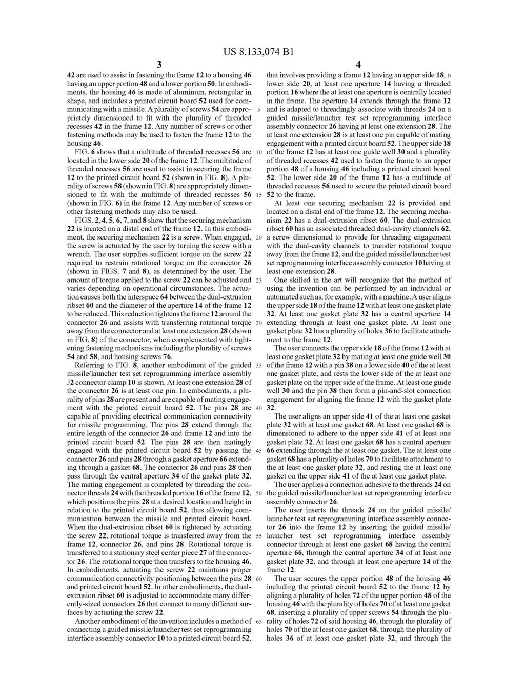
6 1 GUIDED MISSILE/LAUNCHER TEST SET REPROGRAMMING INTERFACE ASSEMBLY J2 CONNECTOR CLAMP STATEMENT REGARDING FEDERALLY SPONSORED RESEARCH OR DEVELOPMENT The invention described herein may be manufactured and used by or for the government of the United States of America for governmental purposes without the payment of any roy alties thereon or therefor. FIELD OF THE INVENTION The invention generally relates to clamps, and more par ticularly, to guided missile/launcher test set reprogramming interface assembly J2 connector clamps. BRIEF DESCRIPTION OF THE DRAWINGS FIG. 1 illustrates a top perspective view of a guided mis sile/launcher test set reprogramming interface assembly J2 connector clamp with a gasket, gasket plate (not shown), and a securing mechanism, according to embodiments of the invention. FIG. 2 illustrates a side perspective view of a guided mis sile/launcher test set reprogramming interface assembly J2 connector clamp, shown with the gasket and gasket plate on the same side as a securing mechanism, according to embodi ments of the invention. FIG. 3 illustrates an inverted side perspective view of the assembly J2 connector clamp, shown with the gasket and gasket plate on an opposing side from a securing mechanism (not shown), according to embodiments of the invention. FIG. 4 illustrates an inverted side perspective view of a assembly J2 connector clamp, shown with the gasket and gasket plate on the same side as a securing mechanism, according to embodiments of the invention. FIG. 5 illustrates an isometric top perspective view of a assembly J2 connector clamp, shown with the gasket, gasket plate, and a securing mechanism, according to embodiments of the invention. FIG. 6 illustrates an isometric bottom perspective view of a assembly J2 connector clamp, shown with the gasket, gasket plate, and a securing mechanism, according to embodiments of the invention. FIG. 7 illustrates an unassembled perspective view of a assembly J2 connector clamp, shown with a connector, gas ket, gasket plate, and a securing mechanism, according to embodiments of the invention. FIG. 8 illustrates an unassembled perspective view of a assembly J2 connector clamp, shown with an upper and lower housing, a printed circuit board, the connector, gasket, gasket plate, and a securing mechanism, according to embodiments of the invention. It is to be understood that the foregoing general description and the following detailed description are exemplary and explanatory only and are not to be viewed as being restrictive of the invention, as claimed. Further advantages of this inven tion will be apparent after a review of the following detailed description of the disclosed embodiments, which are illus trated schematically in the accompanying drawings and in the appended claims. DETAILED DESCRIPTION OF EMBODIMENTS OF THE INVENTION The invention generally relates to clamps, and more par ticularly, to guided missile/launcher test set reprogramming interface assembly J2 connector clamps. Clamps are used in a variety of applications in both civilian and military matters. Missile communication systems use connectors to relay commands to and from missiles and printed circuit boards by contact. However, the communica tion systems may fail because contact between the connector and printed circuit board may be degraded or eliminated entirely because rotational torque breaks the connection. Additionally, existing connectors are often used with dedi cated flanges to connect to dedicated surfaces. However, the existing connectors cannot connect to other surfaces using their dedicated flanges. Because of this, it is desirous to find a assembly J2 connector clamp. Referring to the accompanying drawings in which like reference numbers indicate like elements, FIG. 1 illustrates a first aspect of a guided missile/launcher test set reprogram ming interface assembly J2 connector clamp. Reference char acter 10 generally indicates an apparatus of embodiments of the invention. Referring simultaneously to FIGS. 2 through 8, the appa ratus 10 has a frame 12. In an embodiment as shown in FIGS. 5 through 8, the frame 12 has at least one aperture 14. The aperture 14 is centrally located in the frame 12, extends through the entire frame, and has a threaded portion 16 (not shown in FIG. 7) that is adapted to threadingly associate with threads 24 on a connector 26 (shown in FIGS. 7 and 8). In another embodiment, the frame 12 is has an upper side 18 (shown in FIGS. 7 and 8), a lower side 20 (shown in FIG. 6), and at least one securing mechanism 22 (shown in FIGS. 1, 2, 4, 5, 6, 7, and 8). In another embodiment, the frame 12 is stainless steel and the securing mechanism 22 is a screw engaged with a dual-extrusion ribset 60 (shown in FIGS. 1, 2, 4, 5, 6, 7, and 8), and the dual-extrusion ribset has an associ ated threaded dual-cavity channels 62 (shown in FIGS. 7 and 8) that are appropriately dimensioned for threading engage ment with the screw. FIGS. 5through 8 show an interspace 64 exists from and between the dual-extrusion ribset 60 to the aperture 14 of the frame 12. As depicted in FIG. 8, when the securing mechanism 22 is engaged, rotational torque is trans ferred away from the frame 12 and a connector 26 having at least one extension 28. FIGS. 7 and 8 show that the apparatus 10 has at least one guide well 30 through the upper side 18 of the frame 12. The guide well 30 provides for a pin-and-slot connection engage ment with at least one gasket plate 32. Any number of guide wells and gasket plates may be used without detracting from the scope of the invention. In an embodiment shown in FIGS. 7 and 8, the gasketplate 32 has a central aperture 34 extending through the gasket plate. Additionally, the gasketplate 32 has a plurality of holes 36 extending through the gasketplate. A pin 38 is on the lower side 40 of the gasket plate 32 and assists a user in completing the pin-and-slot connection engagement of the gasket plate 32 with the guide well 30 of the frame 12. In embodiments shown in FIGS. 7 and 8, a plurality of threaded recesses 42 are located in the upper side 18 of the frame 12. FIG. 8 shows that the plurality of threaded recesses
7

8 5 plurality of threaded recesses 42 of the frame 12. In another embodiment, the number of plurality of holes 70 and number of plurality of upper screws 54 is four. The user rotates the plurality of upper screws 54, where the upper portion 48 of the housing 46 is tightened to at least one gasket 68, where at least one gasket is tightened to at least one gasket plate 32, and where at least one gasket plate is tight ened to the frame 12. The user secures the printed circuit board 52 to the frame 12 by inserting the plurality of screws 58, which are appro priately dimensioned for the multitude of threaded recesses 56, through the printed circuit board and into the multitude of threaded recesses. The user then rotates the plurality of screws 58 to secure the printed circuit board 52 to the frame 12. The user rotates the guided missile/launcher test set repro gramming interface assembly connector 26, where the guided missile/launcher test set reprogramming interface assembly connector is tightened to the frame 12. Hand or mechanical tightening is sufficient to secure the guided missile/launcher test set reprogramming interface assembly connector 26 to the frame 12. The user actuates at least one securing mechanism 22 by turning the screw, which reduces the diameter of at least one aperture 14 of the frame 12. The diameter reduction tightens the dual-extrusion ribset 60 and transfers rotational torque away from at least one extension 28 to the housing 46. The user secures the upper portion 48 of the housing 46 including a printed circuit board 52 to the lower portion 50 of the housing by aligning the lower housing recesses 80 with upper housing holes 78, inserting housing screws 76 through the upper housing holes and into the lower housing recesses. The housing screws 76 are appropriately dimensioned for both the upper housing holes 78 and lower housing recesses 80. Both the upper housing holes 78 and lower housing recesses 80 are appropriately threaded to accommodate the housing screws 76. The user then rotates the housing screws 76 to tighten the upper portion 48 of the housing 46 to the lower portion of the housing 50. Major advantages of the invention include, but are not limited to several aspects important to maintaining proper missile communication connectivity. The invention prevents rotation of the connector 26 and eliminates strain on the pins 28. Additionally, the invention allows for adjustment for proper pin insertion height and alignment with the printed circuit board 52. After pin alignment, the connector 26 is locked into position with the printed circuit board 52 and housing 46 which prevents damage to the pins 28 because excess rotational torque is transferred to the housing. While the invention has been described, disclosed, illus trated and shown in various terms of certain embodiments or modifications which it has presumed in practice, the scope of the invention is not intended to be, nor should it be deemed to be, limited thereby and such other modifications or embodi ments as may be suggested by the teachings herein are par ticularly reserved especially as they fall within the breadth and scope of the claims here appended. What is claimed is: 1. A clamp, comprising: a frame having an upper side, a lower side, at least one aperture having a threaded portion, and at least one securing mechanism; wherein said at least one aperture extends through said frame and is adapted to threadingly associate with threads on a connector; and wherein when said at least one securing mechanism is actuated, rotational torque is transferred away from said frame and a connector having at least one extension. 2. The clamp according to claim 1, wherein said at least one aperture is centrally located in said frame. 3. The clamp according to claim 1, further comprising at least one guide well through said upper side of said frame and at least one gasket plate, wherein said at least one guide well provides for pin-and-slot connection engagement with said at least one gasket plate. 4. The clamp according to claim 1, further comprising a plurality of threaded recesses in said upper side of said frame, said plurality of threaded recesses fasten said frame to an upperportion of a housing including a printed circuitboard by a plurality of screws appropriately dimensioned to receive said plurality of threaded recesses. 5. The clamp according to claim 4, wherein said frame further comprises a multitude of threaded recesses in said lower side of said frame, said multitude of threaded recesses secure said printed circuit board to said frame by a plurality of screws appropriately dimensioned to receive said multitude of threaded recesses. 6. The clamp according to claim 5, wherein said upper portion of said housing including said printed circuit board further comprises upper housing holes, said upper housing holes secure said upper portion of said housing to a lower portion of said housing by housing screws, said housing screws being appropriately dimensioned to receive lower housing recesses in said lower housing. 7. The clamp according to claim 1, wherein said at least one securing mechanism is located on a distal end of said frame, wherein said at least one securing mechanism is further com prised of a dual-extrusion ribset, said dual-extrusion ribset having an associated threaded dual-cavity channels capable of threading engagement with a screw. 8. The clamp according to claim 7, wherein said at least one securing mechanism is actuated by turning said screw, wherein reducing the diameter of said at least one aperture, wherein tightening said dual-extrusion ribset and transferring said rotational torque from said at least one extension to a housing. 9. The clamp according to claim 1, wherein said at least one extension is at least one pin capable of mating engagement with a printed circuit board. 10. The clamp according to claim 8, wherein said at least one extension being pin(s) and being capable of providing communication connectivity for missile programming, wherein said dual-extrusion ribset is tightened by actuating said screw and rotational torque is transferred away from said at least one extension, wherein said pin(s) maintain said mat ing engagement with a printed circuit board. 11. The clamp according to claim 10, wherein said pin(s) maintain proper communication connectivity positioning with said printed circuit board when said dual-extrusion rib set is tightened by actuating said screw(s). 12. A connector clamp, comprising: a frame having an upper side, a lower side, at least one aperture having a threaded portion, and at least one securing mechanism; at least one connector, each said connector having a threaded portion and at least one extension; wherein said at least one aperture extends through said frame, wherein each said aperture having a threaded portion being adapted to threadingly associate with
9 7 8 threads on each corresponding connector, wherein each 13. The connector clamp according to claim 12, wherein said extension of each corresponding connector extends said at least one aperture is centrally located and extends out of said lower side when mated; and through said frame. wherein said at least one securing mechanism is actuated, rotational torque is transferred away from each said 5 extension. #: :#: ::: ::: :#:
(12) United States Patent (10) Patent No.: US 8,187,032 B1
 United States Patent (10) Patent No.: US 8,187,032 B1") US008187032B1 (12) United States Patent (10) Patent No.: US 8,187,032 B1 Park et al. (45) Date of Patent: May 29, 2012 (54) GUIDED MISSILE/LAUNCHER TEST SET (58) Field of Classification Search... 439/76.1.
US008187032B1 (12) United States Patent (10) Patent No.: US 8,187,032 B1 Park et al. (45) Date of Patent: May 29, 2012 (54) GUIDED MISSILE/LAUNCHER TEST SET (58) Field of Classification Search... 439/76.1.
(12) United States Patent (10) Patent No.: US 7.458,305 B1
 United States Patent (10) Patent No.: US 7.458,305 B1") US007458305B1 (12) United States Patent (10) Patent No.: US 7.458,305 B1 Horlander et al. (45) Date of Patent: Dec. 2, 2008 (54) MODULAR SAFE ROOM (58) Field of Classification Search... 89/36.01, 89/36.02,
US007458305B1 (12) United States Patent (10) Patent No.: US 7.458,305 B1 Horlander et al. (45) Date of Patent: Dec. 2, 2008 (54) MODULAR SAFE ROOM (58) Field of Classification Search... 89/36.01, 89/36.02,
11 Patent Number: 5,584,458 Rando 45) Date of Patent: Dec. 17, (56) References Cited (54) SEAERS FOR U.S. PATENT DOCUMENTS
 Date of Patent: Dec. 17, (56) References Cited (54) SEAERS FOR U.S. PATENT DOCUMENTS") United States Patent (19) III IIHIIII USOO5584458A 11 Patent Number: 5,584,458 Rando 45) Date of Patent: Dec. 17, 1996 (56) References Cited (54) SEAERS FOR U.S. PATENT DOCUMENTS 4,926,722 5/1990 Sorensen
United States Patent (19) III IIHIIII USOO5584458A 11 Patent Number: 5,584,458 Rando 45) Date of Patent: Dec. 17, 1996 (56) References Cited (54) SEAERS FOR U.S. PATENT DOCUMENTS 4,926,722 5/1990 Sorensen
(12) (10) Patent No.: US 8,083,443 B1. Circosta et al. 45) Date of Patent: Dec. 27, 2011
 (10) Patent No.: US 8,083,443 B1. Circosta et al. 45) Date of Patent: Dec. 27, 2011") United States Patent USOO8083443B1 (12) (10) Patent No.: US 8,083,443 B1 Circosta et al. 45) Date of Patent: Dec. 27, 2011 9 (54) POCKET HOLE PLUG CUTTER 5,800,099 A * 9/1998 Cooper... 408.1 R 5,807,036
United States Patent USOO8083443B1 (12) (10) Patent No.: US 8,083,443 B1 Circosta et al. 45) Date of Patent: Dec. 27, 2011 9 (54) POCKET HOLE PLUG CUTTER 5,800,099 A * 9/1998 Cooper... 408.1 R 5,807,036
(12) United States Patent
 United States Patent") (12) United States Patent US007.961391 B2 (10) Patent No.: US 7.961,391 B2 Hua (45) Date of Patent: Jun. 14, 2011 (54) FREE SPACE ISOLATOR OPTICAL ELEMENT FIXTURE (56) References Cited U.S. PATENT DOCUMENTS
(12) United States Patent US007.961391 B2 (10) Patent No.: US 7.961,391 B2 Hua (45) Date of Patent: Jun. 14, 2011 (54) FREE SPACE ISOLATOR OPTICAL ELEMENT FIXTURE (56) References Cited U.S. PATENT DOCUMENTS
(12) United States Patent (10) Patent No.: US 7,805,823 B2. Sembritzky et al. (45) Date of Patent: Oct. 5, 2010
 United States Patent (10) Patent No.: US 7,805,823 B2. Sembritzky et al. (45) Date of Patent: Oct. 5, 2010") US007805823B2 (12) United States Patent (10) Patent No.: US 7,805,823 B2 Sembritzky et al. (45) Date of Patent: Oct. 5, 2010 (54) AXIAL SWAGE ALIGNMENT TOOL (56) References Cited (75) Inventors: David
US007805823B2 (12) United States Patent (10) Patent No.: US 7,805,823 B2 Sembritzky et al. (45) Date of Patent: Oct. 5, 2010 (54) AXIAL SWAGE ALIGNMENT TOOL (56) References Cited (75) Inventors: David
(12) United States Patent (10) Patent No.: US 7,654,911 B2
 United States Patent (10) Patent No.: US 7,654,911 B2") USOO7654911B2 (12) United States Patent (10) Patent o.: US 7,654,911 B2 Cartwright (45) Date of Patent: Feb. 2, 2010 (54) POOL TABLE LEVELIG SYSTEM 3,080,835 A * 3/1963 Guglielmi... 108,116 3,190.405 A
USOO7654911B2 (12) United States Patent (10) Patent o.: US 7,654,911 B2 Cartwright (45) Date of Patent: Feb. 2, 2010 (54) POOL TABLE LEVELIG SYSTEM 3,080,835 A * 3/1963 Guglielmi... 108,116 3,190.405 A
(12) United States Patent (10) Patent No.: US 6,705,355 B1
 United States Patent (10) Patent No.: US 6,705,355 B1") USOO670.5355B1 (12) United States Patent (10) Patent No.: US 6,705,355 B1 Wiesenfeld (45) Date of Patent: Mar. 16, 2004 (54) WIRE STRAIGHTENING AND CUT-OFF (56) References Cited MACHINE AND PROCESS NEAN
USOO670.5355B1 (12) United States Patent (10) Patent No.: US 6,705,355 B1 Wiesenfeld (45) Date of Patent: Mar. 16, 2004 (54) WIRE STRAIGHTENING AND CUT-OFF (56) References Cited MACHINE AND PROCESS NEAN
(12) Patent Application Publication (10) Pub. No.: US 2012/ A1
 Patent Application Publication (10) Pub. No.: US 2012/ A1") US 20120312936A1 (19) United States (12) Patent Application Publication (10) Pub. No.: US 2012/0312936A1 HUANG (43) Pub. Date: Dec. 13, 2012 (54) HOLDING DEVICE OF TABLET ELECTRONIC DEVICE (52) U.S. Cl....
US 20120312936A1 (19) United States (12) Patent Application Publication (10) Pub. No.: US 2012/0312936A1 HUANG (43) Pub. Date: Dec. 13, 2012 (54) HOLDING DEVICE OF TABLET ELECTRONIC DEVICE (52) U.S. Cl....
(12) United States Patent
 United States Patent") (12) United States Patent US007124695B2 (10) Patent No.: US 7,124.695 B2 Buechler (45) Date of Patent: Oct. 24, 2006 (54) MODULAR SHELVING SYSTEM 4,635,564 A 1/1987 Baxter 4,685,576 A 8, 1987 Hobson (76)
(12) United States Patent US007124695B2 (10) Patent No.: US 7,124.695 B2 Buechler (45) Date of Patent: Oct. 24, 2006 (54) MODULAR SHELVING SYSTEM 4,635,564 A 1/1987 Baxter 4,685,576 A 8, 1987 Hobson (76)
(12) United States Patent (10) Patent No.: US 6,920,822 B2
 United States Patent (10) Patent No.: US 6,920,822 B2") USOO6920822B2 (12) United States Patent (10) Patent No.: Finan (45) Date of Patent: Jul. 26, 2005 (54) DIGITAL CAN DECORATING APPARATUS 5,186,100 A 2/1993 Turturro et al. 5,677.719 A * 10/1997 Granzow...
USOO6920822B2 (12) United States Patent (10) Patent No.: Finan (45) Date of Patent: Jul. 26, 2005 (54) DIGITAL CAN DECORATING APPARATUS 5,186,100 A 2/1993 Turturro et al. 5,677.719 A * 10/1997 Granzow...
(12) United States Patent (10) Patent No.: US 6,593,696 B2
 United States Patent (10) Patent No.: US 6,593,696 B2") USOO65.93696B2 (12) United States Patent (10) Patent No.: Ding et al. (45) Date of Patent: Jul. 15, 2003 (54) LOW DARK CURRENT LINEAR 5,132,593 7/1992 Nishihara... 315/5.41 ACCELERATOR 5,929,567 A 7/1999
USOO65.93696B2 (12) United States Patent (10) Patent No.: Ding et al. (45) Date of Patent: Jul. 15, 2003 (54) LOW DARK CURRENT LINEAR 5,132,593 7/1992 Nishihara... 315/5.41 ACCELERATOR 5,929,567 A 7/1999
John J. Vaillancourt Steven L. Camara Daniel W. French NOTICE
 Serial Number Filing Date Inventor 09/152.475 11 September 1998 John J. Vaillancourt Steven L. Camara Daniel W. French NOTICE The above identified patent application is available for licensing. Requests
(12) United States Patent (10) Patent No.: US 9,068,465 B2
 United States Patent (10) Patent No.: US 9,068,465 B2") USOO90684-65B2 (12) United States Patent (10) Patent No.: Keny et al. (45) Date of Patent: Jun. 30, 2015 (54) TURBINE ASSEMBLY USPC... 416/215, 216, 217, 218, 248, 500 See application file for complete
USOO90684-65B2 (12) United States Patent (10) Patent No.: Keny et al. (45) Date of Patent: Jun. 30, 2015 (54) TURBINE ASSEMBLY USPC... 416/215, 216, 217, 218, 248, 500 See application file for complete
(12) United States Patent
 United States Patent") USOO9206864B2 (12) United States Patent Krusinski et al. (10) Patent No.: (45) Date of Patent: US 9.206,864 B2 Dec. 8, 2015 (54) (71) (72) (73) (*) (21) (22) (65) (60) (51) (52) (58) TORQUE CONVERTERLUG
USOO9206864B2 (12) United States Patent Krusinski et al. (10) Patent No.: (45) Date of Patent: US 9.206,864 B2 Dec. 8, 2015 (54) (71) (72) (73) (*) (21) (22) (65) (60) (51) (52) (58) TORQUE CONVERTERLUG
202 19' 19 19' (12) United States Patent 202' US 7,050,043 B2. Huang et al. May 23, (45) Date of Patent: (10) Patent No.
 United States Patent 202' US 7,050,043 B2. Huang et al. May 23, (45) Date of Patent: (10) Patent No.") US00705.0043B2 (12) United States Patent Huang et al. (10) Patent No.: (45) Date of Patent: US 7,050,043 B2 May 23, 2006 (54) (75) (73) (*) (21) (22) (65) (30) Foreign Application Priority Data Sep. 2,
US00705.0043B2 (12) United States Patent Huang et al. (10) Patent No.: (45) Date of Patent: US 7,050,043 B2 May 23, 2006 (54) (75) (73) (*) (21) (22) (65) (30) Foreign Application Priority Data Sep. 2,
(12) United States Patent (10) Patent No.: US 6,217,246 B1
 United States Patent (10) Patent No.: US 6,217,246 B1") USOO6217246B1 (12) United States Patent (10) Patent No.: US 6,217,246 B1 Yu (45) Date of Patent: Apr. 17, 2001 (54) TWO-PIECE PAPER FASTENER HAVING 1978,569 * 10/1934 Dayton... 24/153 ROUNDED SIDES 3,994,606
USOO6217246B1 (12) United States Patent (10) Patent No.: US 6,217,246 B1 Yu (45) Date of Patent: Apr. 17, 2001 (54) TWO-PIECE PAPER FASTENER HAVING 1978,569 * 10/1934 Dayton... 24/153 ROUNDED SIDES 3,994,606
(12) United States Patent (10) Patent No.: US 8,769,908 B1
 United States Patent (10) Patent No.: US 8,769,908 B1") US008769908B1 (12) United States Patent (10) Patent No.: US 8,769,908 B1 Santini (45) Date of Patent: Jul. 8, 2014 (54) MODULAR BUILDING PANEL 4,813,193 A 3, 1989 Altizer.............. (76) Inventor: Patrick
US008769908B1 (12) United States Patent (10) Patent No.: US 8,769,908 B1 Santini (45) Date of Patent: Jul. 8, 2014 (54) MODULAR BUILDING PANEL 4,813,193 A 3, 1989 Altizer.............. (76) Inventor: Patrick
United States Patent (19)
") US006041720A 11 Patent Number: Hardy (45) Date of Patent: Mar. 28, 2000 United States Patent (19) 54 PRODUCT MANAGEMENT DISPLAY 5,738,019 4/1998 Parker... 108/61 X SYSTEM FOREIGN PATENT DOCUMENTS 75 Inventor:
US006041720A 11 Patent Number: Hardy (45) Date of Patent: Mar. 28, 2000 United States Patent (19) 54 PRODUCT MANAGEMENT DISPLAY 5,738,019 4/1998 Parker... 108/61 X SYSTEM FOREIGN PATENT DOCUMENTS 75 Inventor:
(12) Patent Application Publication (10) Pub. No.: US 2009/ A1
 Patent Application Publication (10) Pub. No.: US 2009/ A1") (19) United States US 20090146763A1 (12) Patent Application Publication (10) Pub. No.: US 2009/0146763 A1 Hershtig (43) Pub. Date: Jun. 11, 2009 (54) HIGH Q SURFACE MOUNTTECHNOLOGY Publication Classification
(19) United States US 20090146763A1 (12) Patent Application Publication (10) Pub. No.: US 2009/0146763 A1 Hershtig (43) Pub. Date: Jun. 11, 2009 (54) HIGH Q SURFACE MOUNTTECHNOLOGY Publication Classification
(12) United States Patent
 United States Patent") (12) United States Patent US009682771B2 () Patent No.: Knag et al. (45) Date of Patent: Jun. 20, 2017 (54) CONTROLLING ROTOR BLADES OF A 5,676,334 A * /1997 Cotton... B64C 27.54 SWASHPLATELESS ROTOR 244.12.2
(12) United States Patent US009682771B2 () Patent No.: Knag et al. (45) Date of Patent: Jun. 20, 2017 (54) CONTROLLING ROTOR BLADES OF A 5,676,334 A * /1997 Cotton... B64C 27.54 SWASHPLATELESS ROTOR 244.12.2
(12) United States Patent (10) Patent No.: US 7,708,159 B2. Darr et al. (45) Date of Patent: May 4, 2010
 United States Patent (10) Patent No.: US 7,708,159 B2. Darr et al. (45) Date of Patent: May 4, 2010") USOO7708159B2 (12) United States Patent (10) Patent No.: Darr et al. (45) Date of Patent: May 4, 2010 (54) PLASTIC CONTAINER 4,830,251 A 5/1989 Conrad 6,085,924 A 7/2000 Henderson (75) Inventors: Richard
USOO7708159B2 (12) United States Patent (10) Patent No.: Darr et al. (45) Date of Patent: May 4, 2010 (54) PLASTIC CONTAINER 4,830,251 A 5/1989 Conrad 6,085,924 A 7/2000 Henderson (75) Inventors: Richard
(12) United States Patent (10) Patent No.: US 8,561,977 B2
 United States Patent (10) Patent No.: US 8,561,977 B2") US008561977B2 (12) United States Patent (10) Patent No.: US 8,561,977 B2 Chang (45) Date of Patent: Oct. 22, 2013 (54) POST-PROCESSINGAPPARATUS WITH (56) References Cited SHEET EUECTION DEVICE (75) Inventor:
US008561977B2 (12) United States Patent (10) Patent No.: US 8,561,977 B2 Chang (45) Date of Patent: Oct. 22, 2013 (54) POST-PROCESSINGAPPARATUS WITH (56) References Cited SHEET EUECTION DEVICE (75) Inventor:
(12) United States Patent (10) Patent No.: US 6,347,876 B1
 United States Patent (10) Patent No.: US 6,347,876 B1") USOO6347876B1 (12) United States Patent (10) Patent No.: Burton (45) Date of Patent: Feb. 19, 2002 (54) LIGHTED MIRROR ASSEMBLY 1555,478 A * 9/1925 Miller... 362/141 1968,342 A 7/1934 Herbold... 362/141
USOO6347876B1 (12) United States Patent (10) Patent No.: Burton (45) Date of Patent: Feb. 19, 2002 (54) LIGHTED MIRROR ASSEMBLY 1555,478 A * 9/1925 Miller... 362/141 1968,342 A 7/1934 Herbold... 362/141
DISTRIBUTION STATEMENT A Approved for Public Release Distribution Unlimited
 Serial Number 09/152.477 Filing Date 11 September 1998 Inventor Anthony A. Ruffa NOTICE The above identified patent application is available for licensing. Requests for information should be addressed
(12) Patent Application Publication (10) Pub. No.: US 2013/ A1
 Patent Application Publication (10) Pub. No.: US 2013/ A1") US 2013 0334265A1 (19) United States (12) Patent Application Publication (10) Pub. No.: US 2013/0334265 A1 AVis0n et al. (43) Pub. Date: Dec. 19, 2013 (54) BRASTORAGE DEVICE Publication Classification
US 2013 0334265A1 (19) United States (12) Patent Application Publication (10) Pub. No.: US 2013/0334265 A1 AVis0n et al. (43) Pub. Date: Dec. 19, 2013 (54) BRASTORAGE DEVICE Publication Classification
(12) United States Patent
 United States Patent") (12) United States Patent US007793.996 B2 (10) Patent No.: US 7.793,996 B2 Karlander (45) Date of Patent: Sep. 14, 2010 (54) CRASH BOX AND A METHOD OF (58) Field of Classification Search... 296/18703,
(12) United States Patent US007793.996 B2 (10) Patent No.: US 7.793,996 B2 Karlander (45) Date of Patent: Sep. 14, 2010 (54) CRASH BOX AND A METHOD OF (58) Field of Classification Search... 296/18703,
(12) United States Patent
 United States Patent") USOO8208048B2 (12) United States Patent Lin et al. (10) Patent No.: US 8,208,048 B2 (45) Date of Patent: Jun. 26, 2012 (54) (75) (73) (*) (21) (22) (65) (51) (52) (58) METHOD FOR HIGH DYNAMIC RANGE MAGING
USOO8208048B2 (12) United States Patent Lin et al. (10) Patent No.: US 8,208,048 B2 (45) Date of Patent: Jun. 26, 2012 (54) (75) (73) (*) (21) (22) (65) (51) (52) (58) METHOD FOR HIGH DYNAMIC RANGE MAGING
IIH. United States Patent (19) Chen. (11) Patent Number: 5,318,090 (45. Date of Patent: Jun. 7, 1994
 Chen. (11) Patent Number: 5,318,090 (45. Date of Patent: Jun. 7, 1994") United States Patent (19) Chen 54) ROLLER ASSEMBLY FORVENETIAN BLIND 76 Inventor: Cheng-Hsiung Chen, No. 228, Sec. 2, Chung-Te Rd., Taichung City, Taiwan 21 Appl. No.: 60,278 22 Filed: May 11, 1993 51)
United States Patent (19) Chen 54) ROLLER ASSEMBLY FORVENETIAN BLIND 76 Inventor: Cheng-Hsiung Chen, No. 228, Sec. 2, Chung-Te Rd., Taichung City, Taiwan 21 Appl. No.: 60,278 22 Filed: May 11, 1993 51)
Hinged locking mechanism
 of 8 ( 2 of 3 ) 11/6/2014 6:50 PM United States Patent 5,444,998 James August 29, 1995 Hinged locking mechanism **Please see images for: ( Certificate of Correction ) ** Abstract A hinged locking mechanism
(12) United States Patent (10) Patent No.: US 9.276,333 B1
 United States Patent (10) Patent No.: US 9.276,333 B1") USOO9276333B1 (12) United States Patent (10) Patent No.: US 9.276,333 B1 W (45) Date of Patent: Mar. 1, 2016 (54) TERMINAL BLOCK WITH IMPROVED 8,647,158 B2 * 2/2014 Kawabata... HO1R 9/2608 RAILENGAGING
USOO9276333B1 (12) United States Patent (10) Patent No.: US 9.276,333 B1 W (45) Date of Patent: Mar. 1, 2016 (54) TERMINAL BLOCK WITH IMPROVED 8,647,158 B2 * 2/2014 Kawabata... HO1R 9/2608 RAILENGAGING
(12) United States Patent (10) Patent No.: US 7.684,688 B2
 United States Patent (10) Patent No.: US 7.684,688 B2") USOO7684688B2 (12) United States Patent (10) Patent No.: US 7.684,688 B2 Torvinen (45) Date of Patent: Mar. 23, 2010 (54) ADJUSTABLE DEPTH OF FIELD 6,308,015 B1 * 10/2001 Matsumoto... 396,89 7,221,863
USOO7684688B2 (12) United States Patent (10) Patent No.: US 7.684,688 B2 Torvinen (45) Date of Patent: Mar. 23, 2010 (54) ADJUSTABLE DEPTH OF FIELD 6,308,015 B1 * 10/2001 Matsumoto... 396,89 7,221,863
(12) United States Patent (10) Patent No.: US 6,663,057 B2
 United States Patent (10) Patent No.: US 6,663,057 B2") USOO6663057B2 (12) United States Patent (10) Patent No.: US 6,663,057 B2 Garelick et al. (45) Date of Patent: Dec. 16, 2003 (54) ADJUSTABLE PEDESTAL FOR BOAT 5,297.849 A * 3/1994 Chancellor... 297/344.
USOO6663057B2 (12) United States Patent (10) Patent No.: US 6,663,057 B2 Garelick et al. (45) Date of Patent: Dec. 16, 2003 (54) ADJUSTABLE PEDESTAL FOR BOAT 5,297.849 A * 3/1994 Chancellor... 297/344.
(12) Patent Application Publication (10) Pub. No.: US 2006/ A1
 Patent Application Publication (10) Pub. No.: US 2006/ A1") US 20060239744A1 (19) United States (12) Patent Application Publication (10) Pub. No.: US 2006/0239744 A1 Hideaki (43) Pub. Date: Oct. 26, 2006 (54) THERMAL TRANSFERTYPE IMAGE Publication Classification
US 20060239744A1 (19) United States (12) Patent Application Publication (10) Pub. No.: US 2006/0239744 A1 Hideaki (43) Pub. Date: Oct. 26, 2006 (54) THERMAL TRANSFERTYPE IMAGE Publication Classification
(12) Patent Application Publication (10) Pub. No.: US 2001/ A1
 Patent Application Publication (10) Pub. No.: US 2001/ A1") US 2001 004.8356A1 (19) United States (12) Patent Application Publication (10) Pub. No.: US 2001/0048356A1 Owen (43) Pub. Date: Dec. 6, 2001 (54) METHOD AND APPARATUS FOR Related U.S. Application Data
US 2001 004.8356A1 (19) United States (12) Patent Application Publication (10) Pub. No.: US 2001/0048356A1 Owen (43) Pub. Date: Dec. 6, 2001 (54) METHOD AND APPARATUS FOR Related U.S. Application Data
(12) United States Patent
 United States Patent") US007 153067B2 (12) United States Patent GreenW00d et al. () Patent No.: (45) Date of Patent: Dec. 26, 2006 (54) ROTARY CUTTING TOOL HAVING MULTIPLE HELICAL CUTTING EDGES WITH DIFFERING HELIX ANGLES (76)
US007 153067B2 (12) United States Patent GreenW00d et al. () Patent No.: (45) Date of Patent: Dec. 26, 2006 (54) ROTARY CUTTING TOOL HAVING MULTIPLE HELICAL CUTTING EDGES WITH DIFFERING HELIX ANGLES (76)
issi Field of search. 348/36, , 33) of the turret punch press machine; an image of the
 of the turret punch press machine; an image of the") US005721587A United States Patent 19 11 Patent Number: 5,721,587 Hirose 45 Date of Patent: Feb. 24, 1998 54 METHOD AND APPARATUS FOR Primary Examiner Bryan S. Tung NSPECTNG PRODUCT PROCESSED BY Attorney,
US005721587A United States Patent 19 11 Patent Number: 5,721,587 Hirose 45 Date of Patent: Feb. 24, 1998 54 METHOD AND APPARATUS FOR Primary Examiner Bryan S. Tung NSPECTNG PRODUCT PROCESSED BY Attorney,
(12) United States Patent (10) Patent No.: US 6,770,955 B1
 United States Patent (10) Patent No.: US 6,770,955 B1") USOO6770955B1 (12) United States Patent (10) Patent No.: Coccioli et al. () Date of Patent: Aug. 3, 2004 (54) SHIELDED ANTENNA INA 6,265,774 B1 * 7/2001 Sholley et al.... 7/728 SEMCONDUCTOR PACKAGE 6,282,095
USOO6770955B1 (12) United States Patent (10) Patent No.: Coccioli et al. () Date of Patent: Aug. 3, 2004 (54) SHIELDED ANTENNA INA 6,265,774 B1 * 7/2001 Sholley et al.... 7/728 SEMCONDUCTOR PACKAGE 6,282,095
(12) Patent Application Publication (10) Pub. No.: US 2012/ A1
 Patent Application Publication (10) Pub. No.: US 2012/ A1") US 20120047754A1 (19) United States (12) Patent Application Publication (10) Pub. No.: US 2012/0047754 A1 Schmitt (43) Pub. Date: Mar. 1, 2012 (54) ELECTRICSHAVER (52) U.S. Cl.... 30/527 (57) ABSTRACT
US 20120047754A1 (19) United States (12) Patent Application Publication (10) Pub. No.: US 2012/0047754 A1 Schmitt (43) Pub. Date: Mar. 1, 2012 (54) ELECTRICSHAVER (52) U.S. Cl.... 30/527 (57) ABSTRACT
(12) Patent Application Publication (10) Pub. No.: US 2005/ A1
 Patent Application Publication (10) Pub. No.: US 2005/ A1") (19) United States US 2005O134516A1 (12) Patent Application Publication (10) Pub. No.: Du (43) Pub. Date: Jun. 23, 2005 (54) DUAL BAND SLEEVE ANTENNA (52) U.S. Cl.... 3437790 (75) Inventor: Xin Du, Schaumburg,
(19) United States US 2005O134516A1 (12) Patent Application Publication (10) Pub. No.: Du (43) Pub. Date: Jun. 23, 2005 (54) DUAL BAND SLEEVE ANTENNA (52) U.S. Cl.... 3437790 (75) Inventor: Xin Du, Schaumburg,
(12) United States Patent
 United States Patent") (12) United States Patent Mack USOO686.0488B2 (10) Patent No.: (45) Date of Patent: Mar. 1, 2005 (54) DRILL CHUCK WITH FRONT-END SHIELD (75) Inventor: Hans-Dieter Mack, Sontheim (DE) (73) Assignee: Rohm
(12) United States Patent Mack USOO686.0488B2 (10) Patent No.: (45) Date of Patent: Mar. 1, 2005 (54) DRILL CHUCK WITH FRONT-END SHIELD (75) Inventor: Hans-Dieter Mack, Sontheim (DE) (73) Assignee: Rohm
(12) (10) Patent No.: US 8,307,513 B1. Fitzgerald (45) Date of Patent: Nov. 13, 2012
 (10) Patent No.: US 8,307,513 B1. Fitzgerald (45) Date of Patent: Nov. 13, 2012") United States Patent US008307513B1 (12) (10) Patent No.: Fitzgerald (45) Date of Patent: Nov. 13, 2012 (54) DOOR HINGE WITH INTEGRATED PRESET 3,538,539 A * 1 1/1970 Allison... 16,375 STOPS 3,602,942 A
United States Patent US008307513B1 (12) (10) Patent No.: Fitzgerald (45) Date of Patent: Nov. 13, 2012 (54) DOOR HINGE WITH INTEGRATED PRESET 3,538,539 A * 1 1/1970 Allison... 16,375 STOPS 3,602,942 A
(12) Patent Application Publication (10) Pub. No.: US 2017/ A1
 Patent Application Publication (10) Pub. No.: US 2017/ A1") (19) United States US 201701 01828A1 (12) Patent Application Publication (10) Pub. No.: US 2017/0101828A1 McGowan et al. (43) Pub. Date: (54) PRE-INSTALLED ANTI-ROTATION KEY (52) U.S. Cl. FOR THREADED
(19) United States US 201701 01828A1 (12) Patent Application Publication (10) Pub. No.: US 2017/0101828A1 McGowan et al. (43) Pub. Date: (54) PRE-INSTALLED ANTI-ROTATION KEY (52) U.S. Cl. FOR THREADED
(12) United States Patent
 United States Patent") USOO7325359B2 (12) United States Patent Vetter (10) Patent No.: (45) Date of Patent: Feb. 5, 2008 (54) (75) (73) (*) (21) (22) (65) (51) (52) (58) (56) PROJECTION WINDOW OPERATOR Inventor: Gregory J. Vetter,
USOO7325359B2 (12) United States Patent Vetter (10) Patent No.: (45) Date of Patent: Feb. 5, 2008 (54) (75) (73) (*) (21) (22) (65) (51) (52) (58) (56) PROJECTION WINDOW OPERATOR Inventor: Gregory J. Vetter,
(12) Patent Application Publication (10) Pub. No.: US 2017/ A1
 Patent Application Publication (10) Pub. No.: US 2017/ A1") (19) United States US 201702O8396A1 (12) Patent Application Publication (10) Pub. No.: US 2017/0208396 A1 Dronenburg et al. (43) Pub. Date: Jul. 20, 2017 (54) ACOUSTIC ENERGY HARVESTING DEVICE (52) U.S.
(19) United States US 201702O8396A1 (12) Patent Application Publication (10) Pub. No.: US 2017/0208396 A1 Dronenburg et al. (43) Pub. Date: Jul. 20, 2017 (54) ACOUSTIC ENERGY HARVESTING DEVICE (52) U.S.
United States Patent (19) [11] Patent Number: 5,746,354
![United States Patent (19) [11] Patent Number: 5,746,354](/thumbs/92/110916574.jpg "United States Patent (19) [11] Patent Number: 5,746,354") US005746354A United States Patent (19) [11] Patent Number: 5,746,354 Perkins 45) Date of Patent: May 5, 1998 54 MULTI-COMPARTMENTAEROSOLSPRAY FOREIGN PATENT DOCUMENTS CONTANER 3142205 5/1983 Germany...
US005746354A United States Patent (19) [11] Patent Number: 5,746,354 Perkins 45) Date of Patent: May 5, 1998 54 MULTI-COMPARTMENTAEROSOLSPRAY FOREIGN PATENT DOCUMENTS CONTANER 3142205 5/1983 Germany...
(12) United States Patent (10) Patent No.: US 6,752,496 B2
 United States Patent (10) Patent No.: US 6,752,496 B2") USOO6752496 B2 (12) United States Patent (10) Patent No.: US 6,752,496 B2 Conner (45) Date of Patent: Jun. 22, 2004 (54) PLASTIC FOLDING AND TELESCOPING 5,929.966 A * 7/1999 Conner... 351/118 EYEGLASS
USOO6752496 B2 (12) United States Patent (10) Patent No.: US 6,752,496 B2 Conner (45) Date of Patent: Jun. 22, 2004 (54) PLASTIC FOLDING AND TELESCOPING 5,929.966 A * 7/1999 Conner... 351/118 EYEGLASS
(12) United States Patent (10) Patent No.: US 7,859,376 B2. Johnson, Jr. (45) Date of Patent: Dec. 28, 2010
 United States Patent (10) Patent No.: US 7,859,376 B2. Johnson, Jr. (45) Date of Patent: Dec. 28, 2010") US007859376B2 (12) United States Patent (10) Patent No.: US 7,859,376 B2 Johnson, Jr. (45) Date of Patent: Dec. 28, 2010 (54) ZIGZAGAUTOTRANSFORMER APPARATUS 7,049,921 B2 5/2006 Owen AND METHODS 7,170,268
US007859376B2 (12) United States Patent (10) Patent No.: US 7,859,376 B2 Johnson, Jr. (45) Date of Patent: Dec. 28, 2010 (54) ZIGZAGAUTOTRANSFORMER APPARATUS 7,049,921 B2 5/2006 Owen AND METHODS 7,170,268
(12) United States Patent (10) Patent No.: US 6,890,073 B2
 United States Patent (10) Patent No.: US 6,890,073 B2") USOO6890O73B2 (12) United States Patent (10) Patent No.: US 6,890,073 B2 DiChiara et al. (45) Date of Patent: May 10, 2005 (54) IMPACT RESISTANT EYE WEAR FRAME FR 592.096 4/1925 ASSEMBLY HAVING ASPLT FRAME
USOO6890O73B2 (12) United States Patent (10) Patent No.: US 6,890,073 B2 DiChiara et al. (45) Date of Patent: May 10, 2005 (54) IMPACT RESISTANT EYE WEAR FRAME FR 592.096 4/1925 ASSEMBLY HAVING ASPLT FRAME
(12) United States Patent (10) Patent No.: US 6,915,597 B2. Jungkind (45) Date of Patent: Jul. 12, 2005
 United States Patent (10) Patent No.: US 6,915,597 B2. Jungkind (45) Date of Patent: Jul. 12, 2005") USOO6915597B2 (12) United States Patent (10) Patent No.: Jungkind (45) Date of Patent: Jul. 12, 2005 (54) SPORTS SHOE 2,523,652 A * 9/1950 Dowd et al.... 36/59 R 3,082.549 A 3/1963 Dolceamore (75) Inventor:
USOO6915597B2 (12) United States Patent (10) Patent No.: Jungkind (45) Date of Patent: Jul. 12, 2005 (54) SPORTS SHOE 2,523,652 A * 9/1950 Dowd et al.... 36/59 R 3,082.549 A 3/1963 Dolceamore (75) Inventor:
(12) United States Patent (10) Patent No.: US 7,854,310 B2
 United States Patent (10) Patent No.: US 7,854,310 B2") US00785431 OB2 (12) United States Patent (10) Patent No.: US 7,854,310 B2 King et al. (45) Date of Patent: Dec. 21, 2010 (54) PARKING METER 5,841,369 A 1 1/1998 Sutton et al. 5,842,411 A 12/1998 Jacobs
US00785431 OB2 (12) United States Patent (10) Patent No.: US 7,854,310 B2 King et al. (45) Date of Patent: Dec. 21, 2010 (54) PARKING METER 5,841,369 A 1 1/1998 Sutton et al. 5,842,411 A 12/1998 Jacobs
(12) United States Patent (10) Patent No.: US 6,387,795 B1
 United States Patent (10) Patent No.: US 6,387,795 B1") USOO6387795B1 (12) United States Patent (10) Patent No.: Shao (45) Date of Patent: May 14, 2002 (54) WAFER-LEVEL PACKAGING 5,045,918 A * 9/1991 Cagan et al.... 357/72 (75) Inventor: Tung-Liang Shao, Taoyuan
USOO6387795B1 (12) United States Patent (10) Patent No.: Shao (45) Date of Patent: May 14, 2002 (54) WAFER-LEVEL PACKAGING 5,045,918 A * 9/1991 Cagan et al.... 357/72 (75) Inventor: Tung-Liang Shao, Taoyuan
USOO A United States Patent (19) 11 Patent Number: 5,931,325. Filipov (45) Date of Patent: Aug. 3, 1999
 11 Patent Number: 5,931,325. Filipov (45) Date of Patent: Aug. 3, 1999") USOO593 1325A United States Patent (19) 11 Patent Number: 5,931,325 Filipov (45) Date of Patent: Aug. 3, 1999 54 ADJUSTABLE MUDRING FOR Primary Examiner Steven Pollard CONVENTIONAL ELECTRICAL OUTLET BOX
USOO593 1325A United States Patent (19) 11 Patent Number: 5,931,325 Filipov (45) Date of Patent: Aug. 3, 1999 54 ADJUSTABLE MUDRING FOR Primary Examiner Steven Pollard CONVENTIONAL ELECTRICAL OUTLET BOX
III IIII III. United States Patent (19) Cheng. 11) Patent Number: 5,529,288 (45) Date of Patent: Jun. 25, 1996
 Cheng. 11) Patent Number: 5,529,288 (45) Date of Patent: Jun. 25, 1996") United States Patent (19) Cheng 54 STRUCTURE OF A HANDRAIL FOR A STARCASE 76 Inventor: Lin Cheng-I, P.O. Box 82-144, Taipei, Taiwan 21 Appl. No.: 284,223 22 Filed: Aug. 2, 1994 (51 Int. Cl.... E04F 11/18
United States Patent (19) Cheng 54 STRUCTURE OF A HANDRAIL FOR A STARCASE 76 Inventor: Lin Cheng-I, P.O. Box 82-144, Taipei, Taiwan 21 Appl. No.: 284,223 22 Filed: Aug. 2, 1994 (51 Int. Cl.... E04F 11/18
Smith et al. (45) Date of Patent: Nov. 26, (73 Assignee: Molex Incorporated, Lisle, Ill. 57) ABSTRACT
 Date of Patent: Nov. 26, (73 Assignee: Molex Incorporated, Lisle, Ill. 57) ABSTRACT") United States Patent (19) 11 US005577318A Patent Number: Smith et al. (45) Date of Patent: Nov. 26, 1996 54 ELECTRICAL TERMINAL APPLICATOR FOREIGN PATENT DOCUMENTS WEMPROVED TRACK ADJUSTMENT 2643514 8/1990
United States Patent (19) 11 US005577318A Patent Number: Smith et al. (45) Date of Patent: Nov. 26, 1996 54 ELECTRICAL TERMINAL APPLICATOR FOREIGN PATENT DOCUMENTS WEMPROVED TRACK ADJUSTMENT 2643514 8/1990
(12) United States Patent (10) Patent No.: US 7,557,281 B1
 United States Patent (10) Patent No.: US 7,557,281 B1") US007557281B1 (12) United States Patent () Patent No.: US 7,557,281 B1 Campling (45) Date of Patent: Jul. 7, 2009 (54) ADJUSTABLE NECK MOUNTING ASSEMBLY 4,295,403 A /1981 Harris FOR ASTRINGED INSTRUMENT
US007557281B1 (12) United States Patent () Patent No.: US 7,557,281 B1 Campling (45) Date of Patent: Jul. 7, 2009 (54) ADJUSTABLE NECK MOUNTING ASSEMBLY 4,295,403 A /1981 Harris FOR ASTRINGED INSTRUMENT
(12) Patent Application Publication (10) Pub. No.: US 2006/ A1
 Patent Application Publication (10) Pub. No.: US 2006/ A1") (19) United States US 2006O151349A1 (12) Patent Application Publication (10) Pub. No.: US 2006/0151349 A1 Andrews et al. (43) Pub. Date: Jul. 13, 2006 (54) TRADING CARD AND CONTAINER (76) Inventors: Robert
(19) United States US 2006O151349A1 (12) Patent Application Publication (10) Pub. No.: US 2006/0151349 A1 Andrews et al. (43) Pub. Date: Jul. 13, 2006 (54) TRADING CARD AND CONTAINER (76) Inventors: Robert
Y 6a W SES. (12) Patent Application Publication (10) Pub. No.: US 2005/ A1. (19) United States. Belinda et al. (43) Pub. Date: Nov.
 Patent Application Publication (10) Pub. No.: US 2005/ A1. (19) United States. Belinda et al. (43) Pub. Date: Nov.") (19) United States US 2005O2521.52A1 (12) Patent Application Publication (10) Pub. No.: Belinda et al. (43) Pub. Date: Nov. 17, 2005 (54) STEELTRUSS FASTENERS FOR MULTI-POSITIONAL INSTALLATION (76) Inventors:
(19) United States US 2005O2521.52A1 (12) Patent Application Publication (10) Pub. No.: Belinda et al. (43) Pub. Date: Nov. 17, 2005 (54) STEELTRUSS FASTENERS FOR MULTI-POSITIONAL INSTALLATION (76) Inventors:
William H. Nedderman, Jr. NOTICE. The above identified patent application is available for licensing. Requests for information should be addressed to:
 _ _ Serial Number Filing Date Inventor 09/332,407 14 June 1999 William H. Nedderman, Jr. NOTICE The above identified patent application is available for licensing. Requests for information should be addressed
75 Inventor: Stephen D. Kuslich, Stillwater, Minn. Primary Examiner Michael Buiz
 US006056749A United States Patent (19) 11 Patent Number: 6,056,749 Kuslich (45) Date of Patent: May 2, 2000 54 METHOD AND DEVICE FOR FIXING AND 5,601,556 2/1997 Pisharodi. CORRECTING SPONDYLOLSTHESIS 5,800,547
United States Patent (19) Sun
 Sun") United States Patent (19) Sun 54 INFORMATION READINGAPPARATUS HAVING A CONTACT IMAGE SENSOR 75 Inventor: Chung-Yueh Sun, Tainan, Taiwan 73 Assignee: Mustek Systems, Inc., Hsinchu, Taiwan 21 Appl. No. 916,941
United States Patent (19) Sun 54 INFORMATION READINGAPPARATUS HAVING A CONTACT IMAGE SENSOR 75 Inventor: Chung-Yueh Sun, Tainan, Taiwan 73 Assignee: Mustek Systems, Inc., Hsinchu, Taiwan 21 Appl. No. 916,941
(12) United States Patent
 United States Patent") (12) United States Patent US007576582B2 (10) Patent No.: US 7,576,582 B2 Lee et al. (45) Date of Patent: Aug. 18, 2009 (54) LOW-POWER CLOCK GATING CIRCUIT (56) References Cited (75) Inventors: Dae Woo
(12) United States Patent US007576582B2 (10) Patent No.: US 7,576,582 B2 Lee et al. (45) Date of Patent: Aug. 18, 2009 (54) LOW-POWER CLOCK GATING CIRCUIT (56) References Cited (75) Inventors: Dae Woo
(12) United States Patent
 United States Patent") USOO9443458B2 (12) United States Patent Shang (10) Patent No.: (45) Date of Patent: US 9.443.458 B2 Sep. 13, 2016 (54) DRIVING CIRCUIT AND DRIVING METHOD, GOA UNIT AND DISPLAY DEVICE (71) Applicant: BOE
USOO9443458B2 (12) United States Patent Shang (10) Patent No.: (45) Date of Patent: US 9.443.458 B2 Sep. 13, 2016 (54) DRIVING CIRCUIT AND DRIVING METHOD, GOA UNIT AND DISPLAY DEVICE (71) Applicant: BOE
(12) Patent Application Publication (10) Pub. No.: US 2013/ A1
 Patent Application Publication (10) Pub. No.: US 2013/ A1") (19) United States (12) Patent Application Publication (10) Pub. No.: US 2013/0081252 A1 Markgraf et al. US 2013 0081252A1 (43) Pub. Date: Apr. 4, 2013 (54) ARRANGEMENT FOR FIXINGA COMPONENT INSIDE OF
(19) United States (12) Patent Application Publication (10) Pub. No.: US 2013/0081252 A1 Markgraf et al. US 2013 0081252A1 (43) Pub. Date: Apr. 4, 2013 (54) ARRANGEMENT FOR FIXINGA COMPONENT INSIDE OF
United States Patent (19) Mori
 Mori") United States Patent (19) Mori 11 Patent Number: 45) Date of Patent: Dec. 3, 1991 54 PAPER-CUTTING MACHINE AND METHOD OF CUTTNG PAPER 75) Inventor: 73 Assignee: Chuzo Mori, Katsushika, Japan Carl Manufacturing
United States Patent (19) Mori 11 Patent Number: 45) Date of Patent: Dec. 3, 1991 54 PAPER-CUTTING MACHINE AND METHOD OF CUTTNG PAPER 75) Inventor: 73 Assignee: Chuzo Mori, Katsushika, Japan Carl Manufacturing
(12) United States Patent
 United States Patent") (12) United States Patent USOO867761 OB2 (10) Patent No.: US 8,677,610 B2 Liu (45) Date of Patent: Mar. 25, 2014 (54) CRIMPING TOOL (56) References Cited (75) Inventor: Jen Kai Liu, New Taipei (TW) U.S.
(12) United States Patent USOO867761 OB2 (10) Patent No.: US 8,677,610 B2 Liu (45) Date of Patent: Mar. 25, 2014 (54) CRIMPING TOOL (56) References Cited (75) Inventor: Jen Kai Liu, New Taipei (TW) U.S.
(12) United States Patent (10) Patent No.: US 6,386,952 B1
 United States Patent (10) Patent No.: US 6,386,952 B1") USOO6386952B1 (12) United States Patent (10) Patent No.: US 6,386,952 B1 White (45) Date of Patent: May 14, 2002 (54) SINGLE STATION BLADE SHARPENING 2,692.457 A 10/1954 Bindszus METHOD AND APPARATUS 2,709,874
USOO6386952B1 (12) United States Patent (10) Patent No.: US 6,386,952 B1 White (45) Date of Patent: May 14, 2002 (54) SINGLE STATION BLADE SHARPENING 2,692.457 A 10/1954 Bindszus METHOD AND APPARATUS 2,709,874
(12) United States Patent (10) Patent No.: US 6,345,454 B1
 United States Patent (10) Patent No.: US 6,345,454 B1") USOO634.5454B1 (12) United States Patent (10) Patent No. Cotton (45) Date of Patent Feb. 12, 2002 (54) SHOE HAVING AREMOVABLE SOLE AND 5,661,915. A 9/1997 Smith... 36/15 METHOD OF USE * cited by examiner
USOO634.5454B1 (12) United States Patent (10) Patent No. Cotton (45) Date of Patent Feb. 12, 2002 (54) SHOE HAVING AREMOVABLE SOLE AND 5,661,915. A 9/1997 Smith... 36/15 METHOD OF USE * cited by examiner
(12) Patent Application Publication (10) Pub. No.: US 2002/ A1
 Patent Application Publication (10) Pub. No.: US 2002/ A1") (19) United States US 2002O180938A1 (12) Patent Application Publication (10) Pub. No.: US 2002/0180938A1 BOk (43) Pub. Date: Dec. 5, 2002 (54) COOLINGAPPARATUS OF COLOR WHEEL OF PROJECTOR (75) Inventor:
(19) United States US 2002O180938A1 (12) Patent Application Publication (10) Pub. No.: US 2002/0180938A1 BOk (43) Pub. Date: Dec. 5, 2002 (54) COOLINGAPPARATUS OF COLOR WHEEL OF PROJECTOR (75) Inventor:
(12) Patent Application Publication (10) Pub. No.: US 2012/ A1
 Patent Application Publication (10) Pub. No.: US 2012/ A1") (19) United States US 20120202410A1 (12) Patent Application Publication (10) Pub. No.: US 2012/0202410 A1 Byers (43) Pub. Date: Aug. 9, 2012 54) SHARPENING TOOL Publication Classification (76) Inventor:
(19) United States US 20120202410A1 (12) Patent Application Publication (10) Pub. No.: US 2012/0202410 A1 Byers (43) Pub. Date: Aug. 9, 2012 54) SHARPENING TOOL Publication Classification (76) Inventor:
(12) United States Patent (10) Patent No.: US 7.408,157 B2
 United States Patent (10) Patent No.: US 7.408,157 B2") USOO7408157B2 (12) United States Patent (10) Patent No.: US 7.408,157 B2 Yan (45) Date of Patent: Aug. 5, 2008 (54) INFRARED SENSOR 2007/0016328 A1* 1/2007 Ziegler et al.... TOO.245 (76) Inventor: Jason
USOO7408157B2 (12) United States Patent (10) Patent No.: US 7.408,157 B2 Yan (45) Date of Patent: Aug. 5, 2008 (54) INFRARED SENSOR 2007/0016328 A1* 1/2007 Ziegler et al.... TOO.245 (76) Inventor: Jason
(12) United States Patent (10) Patent No.: US 6,884,014 B2. Stone et al. (45) Date of Patent: Apr. 26, 2005
 United States Patent (10) Patent No.: US 6,884,014 B2. Stone et al. (45) Date of Patent: Apr. 26, 2005") USOO6884O14B2 (12) United States Patent (10) Patent No.: Stone et al. (45) Date of Patent: Apr. 26, 2005 (54) TOLERANCE COMPENSATING MOUNTING 4,682,906. A 7/1987 Ruckert et al.... 403/409.1 DEVICE 4,846,614
USOO6884O14B2 (12) United States Patent (10) Patent No.: Stone et al. (45) Date of Patent: Apr. 26, 2005 (54) TOLERANCE COMPENSATING MOUNTING 4,682,906. A 7/1987 Ruckert et al.... 403/409.1 DEVICE 4,846,614
United States Patent (19) Schoonover et al.
 Schoonover et al.") United States Patent (19) Schoonover et al. (54) 76 (21) 22 (51) (52) (58) 56) FLUID CONTAINER Inventors: Michael I. Schoonover, 1218 W. Atherton, Flint, Mich. 48507; James A. McFadden, 504 Kingswood,
United States Patent (19) Schoonover et al. (54) 76 (21) 22 (51) (52) (58) 56) FLUID CONTAINER Inventors: Michael I. Schoonover, 1218 W. Atherton, Flint, Mich. 48507; James A. McFadden, 504 Kingswood,
(12) Patent Application Publication (10) Pub. No.: US 2011/ A1
 Patent Application Publication (10) Pub. No.: US 2011/ A1") (19) United States (12) Patent Application Publication (10) Pub. No.: US 2011/0185581 A1 Xing et al. US 2011 0185581A1 (43) Pub. Date: Aug. 4, 2011 (54) COMPACT CIRCULAR SAW (75) (73) (21) (22) (30) Inventors:
(19) United States (12) Patent Application Publication (10) Pub. No.: US 2011/0185581 A1 Xing et al. US 2011 0185581A1 (43) Pub. Date: Aug. 4, 2011 (54) COMPACT CIRCULAR SAW (75) (73) (21) (22) (30) Inventors:
part data signal (12) United States Patent control 33 er m - sm is US 7,119,773 B2
 United States Patent control 33 er m - sm is US 7,119,773 B2") US007 119773B2 (12) United States Patent Kim (10) Patent No.: (45) Date of Patent: Oct. 10, 2006 (54) APPARATUS AND METHOD FOR CONTROLLING GRAY LEVEL FOR DISPLAY PANEL (75) Inventor: Hak Su Kim, Seoul
US007 119773B2 (12) United States Patent Kim (10) Patent No.: (45) Date of Patent: Oct. 10, 2006 (54) APPARATUS AND METHOD FOR CONTROLLING GRAY LEVEL FOR DISPLAY PANEL (75) Inventor: Hak Su Kim, Seoul
(12) United States Patent
 United States Patent") (12) United States Patent USOO698.6322B2 (10) Patent No.: US 6,986,322 B2 Lumpkin (45) Date of Patent: Jan. 17, 2006 (54) SQUIRREL PROOF BIRD FEEDER 4,188.913 A 2/1980 Earl et al. 4,327,669 A 5/1982 Blasbalg
(12) United States Patent USOO698.6322B2 (10) Patent No.: US 6,986,322 B2 Lumpkin (45) Date of Patent: Jan. 17, 2006 (54) SQUIRREL PROOF BIRD FEEDER 4,188.913 A 2/1980 Earl et al. 4,327,669 A 5/1982 Blasbalg
(12) United States Patent (10) Patent No.: US 7,650,825 B1
 United States Patent (10) Patent No.: US 7,650,825 B1") USOO7650825B1 (12) United States Patent (10) Patent No.: Lee et al. (45) Date of Patent: Jan. 26, 2010 (54) CASE TRIMMER AND CHAMFER TOOL 4.325,282 A 4, 1982 Schaenzer... 86,24 4.385,546 A 5/1983 Lee...
USOO7650825B1 (12) United States Patent (10) Patent No.: Lee et al. (45) Date of Patent: Jan. 26, 2010 (54) CASE TRIMMER AND CHAMFER TOOL 4.325,282 A 4, 1982 Schaenzer... 86,24 4.385,546 A 5/1983 Lee...
(12) United States Patent (10) Patent No.: US 6,543,599 B2
 United States Patent (10) Patent No.: US 6,543,599 B2") USOO6543599B2 (12) United States Patent (10) Patent No.: US 6,543,599 B2 Jasinetzky (45) Date of Patent: Apr. 8, 2003 (54) STEP FOR ESCALATORS 5,810,148 A * 9/1998 Schoeneweiss... 198/333 6,398,003 B1
USOO6543599B2 (12) United States Patent (10) Patent No.: US 6,543,599 B2 Jasinetzky (45) Date of Patent: Apr. 8, 2003 (54) STEP FOR ESCALATORS 5,810,148 A * 9/1998 Schoeneweiss... 198/333 6,398,003 B1
III. Main N101 ( Y-104. (10) Patent No.: US 7,142,997 B1. (45) Date of Patent: Nov. 28, Supply. Capacitors B
 Patent No.: US 7,142,997 B1. (45) Date of Patent: Nov. 28, Supply. Capacitors B") US007 142997 B1 (12) United States Patent Widner (54) (75) (73) (*) (21) (22) (51) (52) (58) (56) AUTOMATIC POWER FACTOR CORRECTOR Inventor: Edward D. Widner, Austin, CO (US) Assignee: Tripac Systems,
US007 142997 B1 (12) United States Patent Widner (54) (75) (73) (*) (21) (22) (51) (52) (58) (56) AUTOMATIC POWER FACTOR CORRECTOR Inventor: Edward D. Widner, Austin, CO (US) Assignee: Tripac Systems,
(12) United States Patent (10) Patent No.: US 8,757,375 B2
 United States Patent (10) Patent No.: US 8,757,375 B2") US008757375B2 (12) United States Patent (10) Patent No.: US 8,757,375 B2 Huang (45) Date of Patent: Jun. 24, 2014 (54) SUPPORT FOR A TABLET COMPUTER WITH! E:: 1938. Spur 3.32. u et al... A FUNCTION OF
US008757375B2 (12) United States Patent (10) Patent No.: US 8,757,375 B2 Huang (45) Date of Patent: Jun. 24, 2014 (54) SUPPORT FOR A TABLET COMPUTER WITH! E:: 1938. Spur 3.32. u et al... A FUNCTION OF
(12) United States Patent (10) Patent No.: US 7,857,315 B2
 United States Patent (10) Patent No.: US 7,857,315 B2") US007857315B2 (12) United States Patent (10) Patent No.: US 7,857,315 B2 Hoyt (45) Date of Patent: Dec. 28, 2010 (54) MATHODOMINICS 2,748,500 A 6/1956 Cormack... 434,205 4,083,564 A * 4, 1978 Matsumoto...
US007857315B2 (12) United States Patent (10) Patent No.: US 7,857,315 B2 Hoyt (45) Date of Patent: Dec. 28, 2010 (54) MATHODOMINICS 2,748,500 A 6/1956 Cormack... 434,205 4,083,564 A * 4, 1978 Matsumoto...
United States Patent (19) Lund
 Lund") United States Patent (19) Lund 54 BROACHING CUTTER 76 Inventor: David R. Lund, 1823 Cornish Ave., Charleston, S.C. 29412 21 Appl. No.: 903,157 22 Filed: Jul. 30, 1997 Related U.S. Application Data 62 Division
United States Patent (19) Lund 54 BROACHING CUTTER 76 Inventor: David R. Lund, 1823 Cornish Ave., Charleston, S.C. 29412 21 Appl. No.: 903,157 22 Filed: Jul. 30, 1997 Related U.S. Application Data 62 Division
(12) Patent Application Publication (10) Pub. No.: US 2008/ A1
 Patent Application Publication (10) Pub. No.: US 2008/ A1") (19) United States (12) Patent Application Publication (10) Pub. No.: US 2008/0203800 A1 Van de Geer et al. US 200802038.00A1 (43) Pub. Date: Aug. 28, 2008 (54) (75) (73) (21) (22) SELF-COMPENSATING MECHANCAL
(19) United States (12) Patent Application Publication (10) Pub. No.: US 2008/0203800 A1 Van de Geer et al. US 200802038.00A1 (43) Pub. Date: Aug. 28, 2008 (54) (75) (73) (21) (22) SELF-COMPENSATING MECHANCAL
United States Patent Fischell et al.
 United States Patent Fischell et al. 19 US006006124A 11 Patent Number: 6,006,124 (45) Date of Patent: Dec. 21, 1999 54 (75) MEANS AND METHOD FOR THE PLACEMENT OF BRAIN ELECTRODES Inventors: Robert E. Fischell,
(12) United States Patent
 United States Patent") US00755.1711B2 (12) United States Patent Sarment et al. (54) CT SCANNER INCLUDINGA CAMERATO OBTAN EXTERNAL IMAGES OF A PATIENT (75) Inventors: David Phillipe Sarment, Ann Arbor, MI (US); Miodrag Rakic,
US00755.1711B2 (12) United States Patent Sarment et al. (54) CT SCANNER INCLUDINGA CAMERATO OBTAN EXTERNAL IMAGES OF A PATIENT (75) Inventors: David Phillipe Sarment, Ann Arbor, MI (US); Miodrag Rakic,
(12) United States Patent
 United States Patent") USOO7123644B2 (12) United States Patent Park et al. (10) Patent No.: (45) Date of Patent: Oct. 17, 2006 (54) PEAK CANCELLATION APPARATUS OF BASE STATION TRANSMISSION UNIT (75) Inventors: Won-Hyoung Park,
USOO7123644B2 (12) United States Patent Park et al. (10) Patent No.: (45) Date of Patent: Oct. 17, 2006 (54) PEAK CANCELLATION APPARATUS OF BASE STATION TRANSMISSION UNIT (75) Inventors: Won-Hyoung Park,
USOO A United States Patent (19) 11 Patent Number: 5,534,804 Woo (45) Date of Patent: Jul. 9, 1996
 11 Patent Number: 5,534,804 Woo (45) Date of Patent: Jul. 9, 1996") III USOO5534.804A United States Patent (19) 11 Patent Number: Woo (45) Date of Patent: Jul. 9, 1996 (54) CMOS POWER-ON RESET CIRCUIT USING 4,983,857 1/1991 Steele... 327/143 HYSTERESS 5,136,181 8/1992
III USOO5534.804A United States Patent (19) 11 Patent Number: Woo (45) Date of Patent: Jul. 9, 1996 (54) CMOS POWER-ON RESET CIRCUIT USING 4,983,857 1/1991 Steele... 327/143 HYSTERESS 5,136,181 8/1992
United States Patent (19)
") United States Patent (19) Dekerle 11 Patent Number: 45 Date of Patent: Jun. 18, 1991 54 NIPPLE ADAPTER FOR A BOTTLE COMPRISING ASCREW RING 75) Inventor: 73) Assignee: Benoit Dekerle, Evian, France Societe
United States Patent (19) Dekerle 11 Patent Number: 45 Date of Patent: Jun. 18, 1991 54 NIPPLE ADAPTER FOR A BOTTLE COMPRISING ASCREW RING 75) Inventor: 73) Assignee: Benoit Dekerle, Evian, France Societe
United States Patent (19) Rottmerhusen
 Rottmerhusen") United States Patent (19) Rottmerhusen USOO5856731A 11 Patent Number: (45) Date of Patent: Jan. 5, 1999 54 ELECTRICSCREWDRIVER 75 Inventor: Hermann Rottmerhusen, Tellingstedt, Germany 73 Assignee: Metabowerke
United States Patent (19) Rottmerhusen USOO5856731A 11 Patent Number: (45) Date of Patent: Jan. 5, 1999 54 ELECTRICSCREWDRIVER 75 Inventor: Hermann Rottmerhusen, Tellingstedt, Germany 73 Assignee: Metabowerke
United States Patent (19) Vitale
 Vitale") United States Patent (19) Vitale 54) ULTRASON CALLY BONDED NON-WOVEN FABRIC 75 (73) Inventor: Assignee: Joseph Vitale, Charlotte, N.C. Perfect Fit Industries, Monroe, N.C. (21) Appl. No.: 756,423 22) Filed:
United States Patent (19) Vitale 54) ULTRASON CALLY BONDED NON-WOVEN FABRIC 75 (73) Inventor: Assignee: Joseph Vitale, Charlotte, N.C. Perfect Fit Industries, Monroe, N.C. (21) Appl. No.: 756,423 22) Filed:
WA wrippe Z/// (12) United States Patent US 8,091,830 B2. Jan. 10, (45) Date of Patent: (10) Patent No.: Childs
 United States Patent US 8,091,830 B2. Jan. 10, (45) Date of Patent: (10) Patent No.: Childs") US008091830B2 (12) United States Patent Childs (10) Patent No.: (45) Date of Patent: US 8,091,830 B2 Jan. 10, 2012 (54) STRINGER FOR AN AIRCRAFTWING ANDA METHOD OF FORMING THEREOF (75) Inventor: Thomas
US008091830B2 (12) United States Patent Childs (10) Patent No.: (45) Date of Patent: US 8,091,830 B2 Jan. 10, 2012 (54) STRINGER FOR AN AIRCRAFTWING ANDA METHOD OF FORMING THEREOF (75) Inventor: Thomas
(12) Patent Application Publication (10) Pub. No.: US 2003/ A1
 Patent Application Publication (10) Pub. No.: US 2003/ A1") (19) United States (12) Patent Application Publication (10) Pub. No.: US 2003/0062354 A1 Ward US 2003.0062354A1 (43) Pub. Date: (54) (76) (21) (22) (60) (51) (52) WIRE FEED SPEED ADJUSTABLE WELDING TORCH
(19) United States (12) Patent Application Publication (10) Pub. No.: US 2003/0062354 A1 Ward US 2003.0062354A1 (43) Pub. Date: (54) (76) (21) (22) (60) (51) (52) WIRE FEED SPEED ADJUSTABLE WELDING TORCH
(12) Patent Application Publication (10) Pub. No.: US 2017/ A1
 Patent Application Publication (10) Pub. No.: US 2017/ A1") (19) United States US 201701 22498A1 (12) Patent Application Publication (10) Pub. No.: US 2017/0122498A1 ZALKA et al. (43) Pub. Date: May 4, 2017 (54) LAMP DESIGN WITH LED STEM STRUCTURE (71) Applicant:
(19) United States US 201701 22498A1 (12) Patent Application Publication (10) Pub. No.: US 2017/0122498A1 ZALKA et al. (43) Pub. Date: May 4, 2017 (54) LAMP DESIGN WITH LED STEM STRUCTURE (71) Applicant:
58 Field of Search... 66/216, 222, 223, tively arranged in an outertrack thereof, and the needle
 USOO6112558A United States Patent (19) 11 Patent Number: 6,112,558 Wang (45) Date of Patent: Sep. 5, 2000 54) COMPUTER-CONTROLLED GROUND MESH Primary Examiner Danny Worrell JACQUARD KNITTING MACHINE Attorney,
(12) Patent Application Publication (10) Pub. No.: US 2009/ A1
 Patent Application Publication (10) Pub. No.: US 2009/ A1") (19) United States (12) Patent Application Publication (10) Pub. No.: US 2009/0073337 A1 Liou et al. US 20090073337A1 (43) Pub. Date: Mar. 19, 2009 (54) (75) (73) (21) (22) (30) LCD DISPLAY WITH ADJUSTABLE
(19) United States (12) Patent Application Publication (10) Pub. No.: US 2009/0073337 A1 Liou et al. US 20090073337A1 (43) Pub. Date: Mar. 19, 2009 (54) (75) (73) (21) (22) (30) LCD DISPLAY WITH ADJUSTABLE
United States Patent (19)
") United States Patent (19) 11 US006023898A Patent Number: JOSey (45) Date of Patent: Feb. 15, 2000 54 METAL FRAME BUILDING 4,050,498 9/1977 Lucchetti... 52?657 X CONSTRUCTION 4,283,892 8/1981 Brown. 4,588,156
United States Patent (19) 11 US006023898A Patent Number: JOSey (45) Date of Patent: Feb. 15, 2000 54 METAL FRAME BUILDING 4,050,498 9/1977 Lucchetti... 52?657 X CONSTRUCTION 4,283,892 8/1981 Brown. 4,588,156
Hsu (45) Date of Patent: Jul. 27, PICTURE FRAME Primary Examiner-Kenneth J. Dorner. Assistant Examiner-Brian K. Green
 Date of Patent: Jul. 27, PICTURE FRAME Primary Examiner-Kenneth J. Dorner. Assistant Examiner-Brian K. Green") III United States Patent (19) 11) US005230172A Patent Number: 5,230,172 Hsu (45) Date of Patent: Jul. 27, 1993 54 PICTURE FRAME Primary Examiner-Kenneth J. Dorner o Assistant Examiner-Brian K. Green 76)
III United States Patent (19) 11) US005230172A Patent Number: 5,230,172 Hsu (45) Date of Patent: Jul. 27, 1993 54 PICTURE FRAME Primary Examiner-Kenneth J. Dorner o Assistant Examiner-Brian K. Green 76)
(12) Patent Application Publication (10) Pub. No.: US 2005/ A1
 Patent Application Publication (10) Pub. No.: US 2005/ A1") (19) United States (12) Patent Application Publication (10) Pub. No.: US 2005/0064060 A1 Wagner et al. US 2005OO64060A1 (43) Pub. Date: Mar. 24, 2005 (54) (75) (73) (21) (22) (63) MOLDING APPARATUS FOR
(19) United States (12) Patent Application Publication (10) Pub. No.: US 2005/0064060 A1 Wagner et al. US 2005OO64060A1 (43) Pub. Date: Mar. 24, 2005 (54) (75) (73) (21) (22) (63) MOLDING APPARATUS FOR
(12) United States Patent (10) Patent No.: US 6,957,665 B2
 United States Patent (10) Patent No.: US 6,957,665 B2") USOO6957665B2 (12) United States Patent (10) Patent No.: Shin et al. (45) Date of Patent: Oct. 25, 2005 (54) FLOW FORCE COMPENSATING STEPPED (56) References Cited SHAPE SPOOL VALVE (75) Inventors: Weon
USOO6957665B2 (12) United States Patent (10) Patent No.: Shin et al. (45) Date of Patent: Oct. 25, 2005 (54) FLOW FORCE COMPENSATING STEPPED (56) References Cited SHAPE SPOOL VALVE (75) Inventors: Weon
(12) Patent Application Publication (10) Pub. No.: US 2014/ A1
 Patent Application Publication (10) Pub. No.: US 2014/ A1") (19) United States US 2014.0062180A1 (12) Patent Application Publication (10) Pub. No.: US 2014/0062180 A1 Demmerle et al. (43) Pub. Date: (54) HIGH-VOLTAGE INTERLOCK LOOP (52) U.S. Cl. ("HVIL") SWITCH
(19) United States US 2014.0062180A1 (12) Patent Application Publication (10) Pub. No.: US 2014/0062180 A1 Demmerle et al. (43) Pub. Date: (54) HIGH-VOLTAGE INTERLOCK LOOP (52) U.S. Cl. ("HVIL") SWITCH