Instruction Manual. The Clear Choice! Aluminum Railing. Stainless Railing. Cable Railing. Trellis Systems. Maintenance Free. 316 Stainless Steel
|
|
|
- Edmund Parsons
- 5 years ago
- Views:
Transcription

1 Instruction Manual Aluminum Railing Stainless Railing Cable Railing Trellis Systems Maintenance Free 316 Stainless Steel Virtually Invisible Light Strong Durable Custom Colors The Clear Choice! 1
2 Table of Contents Page: 1: Cover 2: Table of Contents 3: General Text Instructions 4: Aluminum Railing_ Install Base Plates 5: Mounting Posts 6: Fascia Mount Posts 7: Fascia Mount Posts 8: Post Layout 9: Top Rail Attachment 10: Splice Installation 11: End Caps 12: Installing Cables 13: Hand Swage Instructions 14: Lock T Instructions 15: Stair Assembly 16: Intermediate Stair Post Rail Connection 17: Stair Post Railing Connection 18: Stair Post Cable Connection 19: Stainless Post Instructions 20: Stainless Post Layout & Mounting 21: Stainless Picket Installation 22: Transformer Top Installation 23: Wood Top Rail Adapter 24: Lighting 2
3 General Text Instructions 1: Install Base Plates or Drill 3/8 Mounting Holes in Fascia Mounted Posts 2: Install Blocking at all Post Locations 3: Mount Termination Posts_ Shim and Plumb if Needed 4: Run a String Line on Outside of Termination Posts 5: Mount Intermediate Posts_ Space Evenly _ Plumb on String line 6: Follow SCS Layout 7: Install Top Rail 8: Splice All Butts and Angles_ Bisket Joint all Wood Butts and Angles 9: Install Flat Infill 10: Install End Caps 11: Install Cables 12: Run Cables Through all Intermediate Posts 13: Hand Swage Opposite End in the Field 14: Tension all Cables from Center Out 15: Double Nut and Cut off Excess Bolt 16: Remove Double Nuts and Clean Threads 17: Install Acorn Nuts 3
4 Aluminum Railing Aluminum Railing Stainless Cable Solutions has engineered our railing systems to comply with current building codes. Variations of installation are not recommended. SCS encourages customers to read the instructions before calling SCS for support. Tools: 1: Pencil 2: Tape Measure 3: Level 4: Square 5: Speed Square 6: String Line 7: Hammer 8: Rubber Mallet 9: Drill 10: Impact Driver w/ #40 Torx Bit 11: Diablo Carbide Tip Chop Saw Blade tooth 12: Drill Bits 5/32 5/16 3/8 13: Grinder w/ Cut Off Disc 14: 10 mm 11mm Socket Wrench 15: File 1: Install Base Plates: Figure 1: Aluminum Rail Assembly 1a: Keep all bags on posts do not mar finish! 1b: Make a jig to hold posts on bench. Set two doubled up 2x4s 2 5/16 apart. 1c: Apply small amount of grease on base plate screws_ BPS100. 1d: Drive BPS100 with impact driver w/ Torx #40 bit. 1e: Base Plates mount on bottom of post with hole 2 1/2 from bottom of post. 2 2: Fascia Mount: 2a: Drill 3/8 holes on fascia mount portion of the posts. Space holes out as far as possible. THROUGH BOLT ONLY FOR FASCIA MOUNTED POSTS! 2b: Install bottom post caps before mounting. 4
5 Mounting Posts 3: Install Posts Figure 2: Lag Mounting Assembly 3a: Install blocking at all post locations. Lag bolts must penetrate 4 at all locations. Pre Drill Shank at 3/8. Drill Pilot Lag : 9/32 Softwood 5/16 Hardwood 3b: Install all termination posts FIRST shim and plumb FOLLOW SCS LAYOUT! 3c: If you have one post with BASEPLATE on the 90 degree corner set posts so the single set of holes face the return. LOCK T SIDE! 3d: Set string line on outside of termination posts. Space and set intermediate posts plumb on string line evenly. Again, follow SCS layout doc. Use common sense and space posts evenly on all runs. Figure 3: Through Bolt Assembly 5
6 Fascia Mount Post 6: Fascia Mount Posts_ Parallel Joist 6a: Drill 3/8 holes in rim joist. MATCH up holes on Fascia Mt. Backing Plate _FMBP100 6b: Install thru bolts. 6c: Install SCW100 and LOCK washer ONLY on outside face. Do not stack with flat washer. You will not be able to snap on the plastic CW100 over lag head. 6
7 Fascia Mount Posts 7
8 Post Layout 4: Post Layout Figure 4: Parts List 4a : Install all marked termination posts at there location marked on SCS layout. Bags are marked do not take bags off posts. 4b: Make sure that the single hole on all 90 degree corner posts face the correct way for the lock Ts! 4c: Intermediate posts should be laid out evenly for all runs. Posts should not exceed 5 OC spacing. FOLLOW SCS LAYOUT! 4d: Posts inner edges on outside corners on fascia mount should not exceed 3. Figure 5: Aluminum Railing Assembly 8
9 Top Rail Attachment 5: Top Rail Attachment 5a: Use as long of top rail as possible. 5b: Join all straight connections or butt joints over the center of posts. 5c: Pre - drill 5/64 directly in center of post and screw fast with #10 X 5/8 _ SD100. 5d: Cut Flat Infill to fit in between the posts. Make sure flat infill is TIGHT between posts to prevent rattling. Note: If flat infill is loose apply a staggered dab of clear silicone on inside edges of flat infill to prevent rattling. Note: Cut top rail and flat infill with a diablo blade on your chop saw tooth. Wear eye and hearing protection! Figure 6: Top Railing Assembly 9
10 Splice Installation Figure 5: Butt Joint Assembly 6: Splice all Joints 6a: Break all joints over center of posts. 6b: Install splices inside top rail channel. SCS splices are pre welded at 90 degrees and 135 degrees. Note: If your project has a angle that is not standard you will have to cut this angle on the splice material. Take the splice to a welder in your area and have them tacked. Note: If you are a caveman carpenter use JB Weld. 6c: Pre Drill all holes 5/64 as illustrated and screw fast with SDS100. Figure 6: 90 Degree Miter Joint Assembly 10
11 Install End Caps 7: Install End Caps 7a: Screw fast end caps with ECS34 End Cap Screw #6 X 3/4 ss Phillips 7c: Lubricate Screw 7b: HAND DRIVE ONLY! Figure 7 End Cap Assembly 11
12 Installing Cables 8: Install Cables 8a: Slide cables through termination post and let termination or tensioning terminal rest on outside face. 8b: Feed cable through all intermediate posts to the other side. Make sure you count your holes and are feeding the cable correctly. 8c: Hand swage the opposite hardware in the field and install. (See Hand Swage Instructions) Note: If you are machine swaging the hardware in the field with the M1 tool watch provided video. 8d: Repeat until all strands are installed. 8e: Tension all cables to 250 lbs. Start from center and work back and forth top and bottom. Use common sense. Be careful not to over tension, stainless is notorious for locking up. (Galling) 8f: Double nut and cut off the excess stud with a STAINLESS cutoff disc on a 4 grinder. Do not contaminate the stainless with mild steel dust. It will rust. 8g: Clean slag with bastard file. Remove double nut. Install stainless acorn nut. Figure 8 : Cable Assembly 12

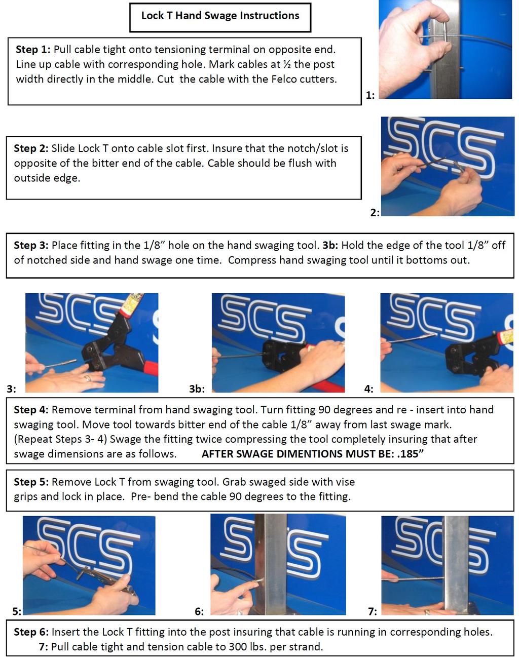
13 Hand Swage Instructions 13
14 Lock T Instructions 14
15 Stair Assembly Figure 9: Stair Railing Assembly Stainless Stair Post Installation Video: Warning: Stairs are one of the toughest things to do in the construction world. If you are a home owner who thinks he is a carpenter get ready for a rude awaking. General contractors who do not do this all the time struggle with stairs. Throw in a material like metal that most have not worked with and it is a recipe for disaster. SCS tries to supply instructions for all applications but again, every stair is different. Hire a contractor if you do not know what plumb, level and square is and fully understand the complexities' of stairs. SCS will provide support but you must know your limitations. 15
16 Intermediate Stair Post Rail Connection Figure 10: Intermediate Stair Post Rail Assembly 16
17 Stair Post Railing Connection Figure 11: Stainless Railing Assembly 17
18 Stair Post Cable Connections Figure 12: Stair Railing Cable Connection 18
19 Stainless Post Instructions General Text Instructions 1: Install all Termination Posts 2: Set String Line. 3: Set Intermediate Posts 6 OC. 4: Set Pickets in between Intermediate Posts at 3 OC. 5: Install Transformer Tops_ Rivet In Place 6: Install Wood Top Rail_ Miter Angles and Butts over CENTER of posts. Bisket Joint all joints 7: Install Blocking UNDER Top Rail 8: Install Cables Figure 13: Stainless Post Assembly 19
20 Stainless Post Layout & Mounting Stainless Post Layout: 1: Install termination posts. 2: Intermediate posts to be set at 6 OC maximum. 3: Picket mounted to BOTTOM of blocking at 3 OC maximum. Mounting 1: Blocking to be installed at all post lag location with 4 minimum lag penetration. Figure 14: Stainless Post Layout Figure 15: Lag Bolt Mounting Assembly 20
21 Stainless Picket Installation Figure 16: Picket Assembly Stainless Picket Installation: 1: Install blocking at all picket locations. 2: Mount pickets with 3/8 x 4 lags. 3: Pre Drill : Shank at 3/8. Pilot : 9/32 Softwood Pilot : 5/16 Hardwood 4: Install flat washer LBW38 and lock washer LBLW38. 5: Use bar soap on lag threads. Drive with 9/16 socket wrench. Do not use impact driver! 6: Install picket post tops. 7: Slide o rings over top insert. 8: Slide into picket until flush 9: Hog out pre drilled holes to 3/16 for rivets. Insert BOTH rivets pop in place 10: Screw up through picket post top into the blocking with #10 X 2 1/2 Block to Rail Screw_ BRS25. Pre-drill all with 1/8 drill bit. Soap all screws DO NOT SNAP OFF HEADS! 21
22 Transformer Top Installation Figure 17: Top Rail & Blocking Assembly Transformer Top Installation: 1: Slip transformer tops into stainless post. Ensure that you put the 90 degree and 135 degree tops at right location. Follow SCS layout. 2: Drill 3/16 holes in line with cable holes on each side of the post and rivet fast. 22


23 Wood Top Rail Adapter WTRA180 _WOOD TOP RAIL ADAPTER INSTRUCTIONS Step 1: Pre Thread Holes with BPS100_ Base Plate Screw Use Torx # 40 Bit and Impact Driver Step 2 : Drive in the WTRAS100_ Wood Top Rail Adapter Screw Make sure that the WTRA lines up correctly with cables drill hole pattern. Router WTRA180 into top rail to hide edges. Countersink heads of WTRAS
24 Lighting Installation 24
25 LED Lighting Installation 25

26 Stainless Cable Solutions STAINLESS CABLE SOLUTIONS SE 114th Ave Clackamas, OR Toll Free: Direct: Fax: The Clear Choice! 26
27 27
28 28
ATLANTIS RAIL Contact Information
 ATLANTIS RAIL Contact Information Customer Service (800) 541-6829 (508) 732-9191 Spectrum System Installation Instructions Atlantis Rail s Spectrum System is an easy to install, universal cable railing
Horizontal Cable Systems
 ALUMINUM RAILING INSTALLATION INSTRUCTIONS v2012 orizontal Cable Systems 1) Check Contents Of Packages: Verify that all parts have arrived and that they match the packing list. 1A) Coastal applications:
Horizontal Cable Systems
 ALUMINUM RAILING INSTALLATION INSTRUCTIONS Horizontal Cable Systems 1) Check Contents Of Packages: Verify that all parts have arrived and that they match the packing list. 1A) Coastal applications: Confirm
Clearview Railing System Installation Instructions
 Clearview Railing System Installation Instructions Disclaimer: AGS Stainless, Inc. has its Clearview Railing Systems designed by a professional engineer to meet the requirements of the latest national
ATLANTIS RAIL Contact Information: Atlantis Rail Systems 70 Armstrong Road 3900 Civic Center Drive Plymouth, MA North Las Vegas, NV 89030
 ATLANTIS RAIL Contact Information: Atlantis Rail Systems 70 Armstrong Road 3900 Civic Center Drive Plymouth, MA 02360 North Las Vegas, NV 89030 (800) 541-6829 or (508) 732-9191 (508) 732-9798 www.atlantisrail.com
Cable Cutter Square. 25 Tape Measure. Chalk Line Level Loctite 242 Blue
 ATLANTIS RAIL Contact Information: Atlantis Rail Systems 70 Armstrong Road 3900 Civic Center Drive Plymouth, MA 02360 North Las Vegas, NV 89030 (800) 541-6829 or (508) 732-9191 (508) 732-9798 www.atlantisrail.com
ATLANTIS RAIL HandiSwage Installation Instructions ATLANTIS RAIL Contact Information Atlantis Rail Systems November, 2013
 ATLANTIS RAIL HandiSwage Installation Instructions ATLANTIS RAIL Contact Information Atlantis Rail Systems November, 2013 Atlantis Rail s HandiSwage System is an easy to use cable railing product utilizing
Now available at participating Feeney (2/14) AF# A. Stores. 1/8'' Stainless Steel Cable Assemblies to Enhance Any Railing and Any View!
 AF# A. Stores. 1/8'' Stainless Steel Cable Assemblies to Enhance Any Railing and Any View!") 2014 Feeney (2/14) AF# 2009-236A Now available at participating Stores 1/8'' Stainless Steel Cable Assemblies to Enhance Any Railing and Any View! Easy-to-install, prefabricated cable assemblies are an
2014 Feeney (2/14) AF# 2009-236A Now available at participating Stores 1/8'' Stainless Steel Cable Assemblies to Enhance Any Railing and Any View! Easy-to-install, prefabricated cable assemblies are an
PARTS INCLUDED IN FIXED STAIR CABLE RAIL KIT:
 175 SERIES FIXED STAIR CABLE RAIL - INSTALLATION INSTRUCTIONS PARTS INCLUDED IN FIXED STAIR CABLE RAIL KIT: FIXED STAIR TOP RAIL (1) A FIXED STAIR BOTTOM RAIL (1) B D UPPER SADDLE BRACKET (1) C BRACKET
1. TOOLS + MATERIALS REQUIRED
 R INSTALLATION INSTRUCTIONS PRODUCT: BALDUR + ODEN CONFIGURATION: BI-PARTING DOOR MOUNT: TOP MOUNT Product is covered by U.S. patents. For more information visit www.krownlab.com. TOOLS + MATERIALS REQUIRED
ALUMINUM RAILING INSTALLATION INSTRUCTIONS. 1) Check Contents Of Packages: Verify that all parts have arrived and that they match the packing list.
 Check Contents Of Packages: Verify that all parts have arrived and that they match the packing list.") ALUMINUM RAILING INSTALLATION INSTRUCTIONS AF#2010-308A Glass Infill Systems 1) Check Contents Of Packages: Verify that all parts have arrived and that they match the packing list. 2) Gather and Identify
ALUMINUM RAILING INSTALLATION INSTRUCTIONS AF#2010-308A Glass Infill Systems 1) Check Contents Of Packages: Verify that all parts have arrived and that they match the packing list. 2) Gather and Identify
Open Up Your View With CABLE SYSTEMS
 Open Up Your View With CABLE SYSTEMS PRESENTED BY CROWN HERITAGE Our Cable Multiple options to accomodate any deck or stair design Marine Grade 316 stainless steel Swaging is the term used for attaching
400A 40113V, 401A 40120V, & 401AL 40120VL ALUMINUM VERTICAL 4000 LB LIFT INCLUDES SCREW LEG ASSEMBLY INSTRUCTIONS
 12/11/07 PAGE 1 OF 12 400A 40113V, 401A 40120V, & 401AL 40120VL ALUMINUM VERTICAL 4000 LB LIFT INCLUDES SCREW LEG ASSEMBLY INSTRUCTIONS Thank you for purchasing our product! *Please read these instructions
ALUMINUM RAILING INSTALLATION INSTRUCTIONS. 1) Check Contents Of Packages: Verify that all parts have arrived and that they match the packing list.
 Check Contents Of Packages: Verify that all parts have arrived and that they match the packing list.") ALUMINUM RAILING INSTALLATION INSTRUCTIONS AF#2010-308D Glass Infill Systems 1) Check Contents Of Packages: Verify that all parts have arrived and that they match the packing list. 2) Gather and Identify
ALUMINUM RAILING INSTALLATION INSTRUCTIONS AF#2010-308D Glass Infill Systems 1) Check Contents Of Packages: Verify that all parts have arrived and that they match the packing list. 2) Gather and Identify
Template. Blue 242. May 2018 trademarks of Suncor Stainless, Inc. Loctite is a registered trademark of Henkel Corporation
 ATLANTIS RAIL Contact Information: Atlantis Rail Systems 70 Armstrong Road 3900 Civic Center Drive Plymouth, MA 02360 North Las Vegas, NV 89030 (800) 541-6829 or (508) 732-9191 (508) 732-9798 www.atlantisrail.com
Fortress Al HOME posts must always be secured to the deck framing. Fortress Al HOME posts should never be attached to only the deck boards.
 Installation Instructions for Fortress Al HOME Traditional Adjustable Panels with Simplified and Al HOME Posts It is the responsibility of the installer to meet all code and safety requirements, and to
Level Railing. Installation Guide. v2.5 W W W. S O L U T I O N S A L U M I N U M. C O M
 Level Railing Installation Guide Top Rail Bottom Rail Aluminum Baluster 2x Bottom Bracket 1x Rail Support #909915 Kit Includes: 1 - Top Rail (with Baluster Connectors installed) 1 - Bottom Rail (with Baluster
Fortress Al Posts must always be secured to the deck framing. Fortress Al Posts should never be attached to only the deck boards.
 Installation Instructions for Fortress Railing Traditional Panels with s and Posts It is the responsibility of the installer to meet all code and safety requirements, and to obtain all required building
Tape Measure Carpenter s Square Touch-up Paint Chalk Line. Blue 242. Template
 ATLANTIS RAIL Contact Information: Atlantis Rail Systems 70 Armstrong Rd. Plymouth, MA 02360 (800) 541-6829 or (508) 732-9191 (508) 732-9798 www.atlantisrail.com NOVA System Installation Instructions The
MOTORIZED STANDARD SHADE WITH CABLES Installation Instructions
 Tools Needed Drill Measuring Tape Pencil 2 Level Plumb Line ¼ Masonry Drill Bit Hammer Linesmans Pliers Cable Cutters Phillips & Flat-Head Screw Driver 11/32 Socket or Open End Wrench 5/32 Allen Wrench
Create cable assemblies to fit your style
 2015 Feeney (11/15) Quick-Connect Brochure #2015-975B Create cable assemblies to fit your style Quick-Connect Solutions Guide The fast and easy way to create your own CableRail assemblies! Our CableRail
INSTALLATION INSTRUCTIONS. Level Rail With Cap: Page 2 Level Rail Without Cap: Page 8 Stair Rail: Page 12
 INSTALLATION INSTRUCTIONS Level Rail With Cap: Page 2 Level Rail Without Cap: Page 8 Stair Rail: Page 12 LEVEL RAIL WITH CAP The testing was performed in accordance with procedures and methods referenced
INSTALLATION VIDEOS ONLINE
 Railing Installation Guide GLASS PICKET CABLE INSTALLATION VIDEOS ONLINE Videos are broken up into small segments which covers most aspects of glass, picket, and cable railing installations. Cable railing
Classic Roll Tarp. Installation Instructions. Attention Dealers: Please give this owners manual to the customer when the product is delivered.
 Serving the Truck & Trailer Industry Since 1944 Classic Roll Tarp Attention Dealers: Please give this owners manual to the customer when the product is delivered. Call 800-535-9545 www.aeroindustries.com
Installation Instructions
 Important 1. Acclimate materials 24 hrs before installation. Maintain temperature controlled environment after installation 2. Install in accordance with manufacturer s installation instructions. Failure
Cable Railing Kit Application Guide
 Cable Railing Kit Application Guide January 2019 Nationwide Industries 10333 Windhorst Rd. Tampa, FL 33619 813.988.2628 Fax: 813.988.3465 Photo courtesy of FabWorx Framework You Will Need for Cable Railing
ATTRACTIVE VERSATILE DURABLE
 CABLERAIL 7 CHECK THE CABLERAIL ADVANTAGES Attractive, affordable, and very low-maintenance. Invisible appearance will not impair views. Made from strong and weather-tough type 6 stainless steel cable.
PRODUCT: LOKI INSTALLATION INSTRUCTIONS. Product is covered by U.S. patents. For more information visit
 R INSTALLATION INSTRUCTIONS PRODUCT: LOKI CONFIGURATION: SINGLE DOOR MOUNT: GLASS MOUNT Product is covered by U.S. patents. For more information visit www.krownlab.com . TOOLS + MATERIALS REQUIRED TOOLS
Installation Instructions 2000/2000W/G Handrail
 Important 1. Acclimate materials 24 hrs before installation. Maintain temperature controlled environment after installation 2. Install in accordance with manufacturer s installation instructions. Failure
WOOD POST FD POST. Installation Guide FD POST MOUNT STAIR / ANGLE RAILING LAG STAIR / ANGLE RAILING STUD CABLE RAILING FITTINGS
 Installation Guide It is the responsibility of the installer to meet or exceed all code and safety requirements, and to obtain all required building permits. These instructions are only a guide and may
Installation Manual Flat Track Series
 Manual Flat Track Series Contents Safety...1 Parts...2 Hardware.......................................... 2 Tools Required..................................... 4.............................................
INSTALLATION INSTRUCTIONS FOR PLASCORE F5075 FRAME WALL
 INSTALLATION INSTRUCTIONS FOR PLASCORE F5075 FRAME WALL The following information is provided by Plascore, Inc., as a general guideline for the installation of the F5075 Frame Wall System. This information
Classic Roll Tarp. Installation Instructions. Attention Dealers: Please give this owners manual to the customer when the product is delivered.
 Serving the Truck & Trailer Industry Since 1944 Classic Roll Tarp Attention Dealers: Please give this owners manual to the customer when the product is delivered. Call 800-535-9545 www.aeroindustries.com
NX7 SERIES 5-1/2 HANDRAIL
 STORAGE & HANDLING The handrails are shipped unassembled. Upon receipt, immediately check all material for any damage that may have occurred in transit and verify that all of the items and quantities are
Handrail Installation. Paramount Cable Railing Systems 49 Stokes Drive Carson City, NV
 Handrail Installation Paramount Cable Railing Systems 49 Stokes Drive Carson City, NV 89721 775.887.1077 NVPIH@AOL.COM Handrail Installation Figure 1: Separate posts, fasteners, and hardware. Check against
1/8 Stainless Steel Cable Assemblies to Enhance Any Railing and Any View!
 2015 Feeney (3/15) Packaged Products Catalog #2011-338D 1/8 Stainless Steel Cable Assemblies to Enhance Any Railing and Any View! Standard Cable Assemblies Easy-to-install, prefabricated cable assemblies
Deck Mount Installation with Bench
 Deck Mount Installation with Bench 1. Mark track with square. 2. Cut tracks with saw. 3. Drill ¼ hole (if needed.) 4. Countersink track. 5. Countersink all track 6. File all track ends. ends. 7. Lay out
The Festival Assembly Instructions
 The Festival Assembly Instructions Toll Free: 866.768.8465 Hours: 9-5 Monday-Friday EST www.homeplacestructures.com Package ships as shown CONTACT INFORMATION: HomePlace Structures 301 Commerce Drive New
CONTENTS TOOL LIST U P S I D E I N N O V A T I O N S, L L C RAMP AND STEP SYSTEM ASSEMBLY INSTRUCTIONS. Revised: June 2013
 U P S I D E I N N O V A T I O N S, L L C RAMP AND STEP SYSTEM ASSEMBLY INSTRUCTIONS TOOL LIST Required Tools: - Reciprocating Saw with Metal Cutting Blade - Drill - 7/16 Drill Bit for Metal Drilling -
Installation Instructions
 Important 1. Acclimate materials 24 hrs before installation. Maintain temperature controlled environment after installation. 2. Install in accordance with manufacturer s installation instructions. Failure
1/8 Stainless Steel Cable Assemblies to Enhance Any Railing and Any View!
 2017 Feeney (2/17) Packaged Products Catalog #2011-338G 1/8 Stainless Steel Cable Assemblies to Enhance Any Railing and Any View! Standard Cable Assemblies Easy-to-install, prefabricated cable assemblies
Kwik-Lock. Installation Instructions. Attention Dealers: Please give this owners manual to the customer when the product is delivered.
 Serving the Truck & Trailer Industry Since 1944 Installation Instructions Attention Dealers: Please give this owners manual to the customer when the product is delivered. Call 800-535-9545 www.aeroindustries.com
2x Bottom Bracket. 1x Rail Support STEP 1 STEP 2
 Level Railing Top Rail Bottom Rail Aluminum Baluster 2x Bottom Bracket 1x Rail Support Kit Includes: 1 - Top Rail (with Baluster Connectors installed) 1 - Bottom Rail (with Baluster Connectors installed)
Fortress Fe Posts must always be secured to the deck framing. Fortress Fe Posts should never be attached to only the deck boards.
 Installation Instructions for FortressCable H-Series Stair Panels with Simplified Stair Bracket SSB-05 and Fe Posts It is the responsibility of the installer to meet all code and safety requirements, and
Installing Cable Railings
 A simple approach to a great upgrade Figure 1. Cable railings exert considerable tension on the end posts. The solution is to use beefier end posts and fill in between them with sub-rails. by Mark Ellis
DekPro Prestige Aluminum Rail System Level Railing Installation Instructions
 ing Installation Guide Please read all instructions completely before starting any installation of DekPro Prestige Railing Systems. SAFETY: Always be safe and follow all instructions when using power tools
The following instructions will guide you through the installation of your new vinyl railing.
 Installation Guide St. James Vinyl T-Rail Tools Required Protective eye glasses 3/8 x 3 Concrete Anchors/Fasteners (for Tape measure concrete installations) Variable speed drill/screwdriver Philips Driver
PRODUCT: BALDUR + ODEN
 R INSTALLATION INSTRUCTIONS PRODUCT: BALDUR + ODEN CONFIGURATION: SINGLE DOOR MOUNT: GLASS MOUNT Product is covered by U.S. patents. For more information visit www.krownlab.com . TOOLS + MATERIALS REQUIRED
4 1/2" [114.3mm] HANDRAIL HEIGHT PER LOCAL CODE AUTHORITY
![4 1/2 [114.3mm] HANDRAIL HEIGHT PER LOCAL CODE AUTHORITY](/thumbs/82/86202782.jpg "4 1/2 [114.3mm] HANDRAIL HEIGHT PER LOCAL CODE AUTHORITY") WITH INTERNATIONAL OFFSET PLEASE READ PLEASE READ THESE INSTRUCTIONS THOROUGHLY PRIOR TO BEGINNING THE INSTALLATION! THIS INSTRUCTION SHEET IS INTENDED TO PROVIDE A SPECIFIC GUIDE TO FOLLOW FOR THE INSTALLATION
WITH INTERNATIONAL OFFSET PLEASE READ PLEASE READ THESE INSTRUCTIONS THOROUGHLY PRIOR TO BEGINNING THE INSTALLATION! THIS INSTRUCTION SHEET IS INTENDED TO PROVIDE A SPECIFIC GUIDE TO FOLLOW FOR THE INSTALLATION
PowerLock. Installation Instructions. Attention Dealers: Please give this owners manual to the customer when the product is delivered.
 Serving the Truck & Trailer Industry Since 1944 FOR Attention Dealers: Please give this owners manual to the customer when the product is delivered. Call 800-535-9545 www.aeroindustries.com Indianapolis,
HANDRAIL HEIGHT PER LOCAL CODE AUTHORITY
 WITH MOUNTING BRACKET PLEASE READ PLEASE READ THESE INSTRUCTIONS THOROUGHLY PRIOR TO BEGINNING THE INSTALLATION! THIS INSTRUCTION SHEET IS INTENDED TO PROVIDE A SPECIFIC GUIDE TO FOLLOW FOR THE INSTALLATION
CRASH RAIL INSTALLATION HEIGHT
 PLEASE READ PLEASE READ THESE INSTRUCTIONS THOROUGHLY PRIOR TO BEGINNING THE INSTALLATION! THIS INSTRUCTION SHEET IS INTENDED TO PROVIDE A SPECIFIC GUIDE TO FOLLOW FOR THE INSTALLATION OF THIS. CONTAINED
March 1, Fax:
 March 1, 2017 U.S.A. Manufacturer The Cable Connection 52 Heppner Drive Carson City, Nevada 89706 800.851.2961 775.885.1443 Fax: 775.885.2734 E-mail: info@ultra-tec.com www.ultra-tec.com Framework You
M2 Antenna Systems, Inc. Model No: 20M6-125
 M2 Antenna Systems, Inc. Model No: 20M6-125 SPECIFICATIONS: Model... 20M6-125 Frequency Range... 14.0 14.350 MHz *Gain, (FS) / Over gnd... 11.19dBi / 16.6dBi @70 Front to back... 25 db Typical Beamwidth...
The following instructions will guide you through the installation of your new vinyl railing stair kit.
 Installation Guide Vinyl Standard Stair Railing Tools Required Protective eye glasses Tape measure Variable speed drill/screwdriver Rotary hammer or hammer drill and masonry percussion bit recommended
VINYL CLASSIC FREESTANDING PERGOLA ASSEMBLY INSTRUCTIONS
 P a g e 1 VINYL CLASSIC FREESTANDING PERGOLA ASSEMBLY INSTRUCTIONS Shown: 8' x 12' Vinyl Classic Pergola with 12" Top and Main Runner Spacing The design of this pergola is based on all posts being installed
INSTALLATION INSTRUCTIONS
 INSTALLATION INSTRUCTIONS SHOWER DOOR KIT ALUMINUM 2503 E. Vernon Avenue, Los Angeles, CA 90058-1826 Phone: (800) 421-6144 EXT. 7740 Fax: (800) 458-7496 crlaurence.com Email: showers@crlaurence.com 11M0260
Installing AZEK Evolutions Rail
 Installing Evolutions Rail TM Contemporary Installing AZEK Evolutions Rail Installing Evolutions Rail Contemporary Style... 2 Installing CableRail by Feeney for Evolutions Rail Contemporary Style... 8
Fortress Fe Posts must always be secured to the deck framing. Fortress Fe Posts should never be attached to only the deck boards.
 Installation Instructions for Fortress Horizontal Cable Panel System with UB-05 Brackets and Fe Posts It is the responsibility of the installer to meet all code and safety requirements, and to obtain all
PowerLock. Installation Instructions. Attention Dealers: Please give this owners manual to the customer when the product is delivered.
 Serving the Truck & Trailer Industry Since 1944 PowerLock Attention Dealers: Please give this owners manual to the customer when the product is delivered. Call 800-535-9545 www.aeroindustries.com Indianapolis,
Locker Pedestal Installation Instructions
 Locker Pedestal Installation Instructions LK-PED-INST-0314r1 Parts List Single Pedestal Back to Back Pedestal Horizontal Support Tube TS-169 Post Flange TS-190 Post Cap Fasteners Provided: #8 x ¾ round
Vinyl Gazebo Instructions
 P a g e 1 Vinyl Gazebo Instructions 10 Vinyl Gazebo Shown Thank you for the purchase of your New Gazebo. Depending on the size of your Gazebo, installation can usually be completed in 1 to 2 days. These
Installation Instructions for. Handrail Component System
 Handrail STEP-BY-STEP Installation Instructions for Handrail Component System Rise in Inches Run in Inches 8 8.5 9 9.5 10 10.5 11 11.5 12 12.5 13 13.5 14 14.5 15 8.5 47 45 43 42 40 39 38 36 35 34 33 32
YUKON PATIO COVER INSTALLATION INSTRUCTIONS
 YUKON PATIO COVER INSTALLATION INSTRUCTIONS Before You Begin: Consult your local building department for any required permits You may be required to obtain a building permit for this structure. Contact
Fortress Fe Posts must always be secured to the deck framing. Fortress Fe Posts should never be attached to only the deck boards.
 Installation Instructions for Fortress Vertical Cable Panel System with Brackets and Fe Posts It is the responsibility of the installer to meet all code and safety requirements, and to obtain all required
Quick Fit Installation Guide Retractable Screen - Double Door
 Quick Fit Installation Guide Retractable Screen - Double Door 1 REMOVE KIT PARTS FROM SHIPPING TUBE 2 Slide bolts 2 Rail receiver Clips 15 Mounting screws 1 Housing end cap screw 2 Handles 1 Housing end
installation care & maintenance instructions lifecycledecking.com 25-year limited residential warranty 20-year limited commercial warranty
 installation care & maintenance instructions lifecycledecking.com 25-year limited residential warranty 20-year limited commercial warranty Installation Instructions As with any building project, use proper
Fireball Fab Welded Baluster Insert Panel System Installation Instructions
 Fireball Fab Welded Baluster Insert Panel System Installation Instructions Prior to construction, check with your local regulatory agency for special code requirements in your area. Common railing height
MTS-ACB. RENOGY Photovoltaic Module Adjustable Curved Bracket E Philadelphia St, Ontario, CA Version: 1.
 MTS-ACB RENOGY Photovoltaic Module Adjustable Curved Bracket 2775 E Philadelphia St, Ontario, CA 91761 1-800-330-8678 1 Version: 1.0 Important Safety Instructions Please save these instructions. This manual
DeckRail A Product of DeckRite LLC 3912 East Progress North Little Rock, AR Phone: (501) Fax: (501)
 Fax: (501)") Deck Rite Welded Picket Railing Installation Guide Disclaimer: This guide is not intended to replace a trained professional installer. The drawings and instructions contained within are for demonstration
Deck Rite Welded Picket Railing Installation Guide Disclaimer: This guide is not intended to replace a trained professional installer. The drawings and instructions contained within are for demonstration
RUN-IN SHED INSTRUCTIONS
 RUN-IN SHED INSTRUCTIONS 14321 5th Line Nassagaweya, Rockwood, ON, N0B 2K0 Phone 519-856-9959 ~ Fax 519-856-4141 Toll Free 1-800-461-3362 ~ Email sales@systemhorse.com Website www.systemfence.com RUN-IN
LOFT DOOR HANGER BARN DOORS & HARDWARE. Hardware Installation Instructions. Page
 LOFT DOOR HANGER Page 1 Specifications 2 7/16" 3/8" 1-1/2 1-3/4 Ø3 3 7/8" 11-1/16 Page 2 Parts and Tools Tools Needed Tape Measure Pencil Drill with 1/8, 1/4 and 3/8 bits, 1 spade bit and Phillips bit
Chalk Line. #4 Phillips Driver Bit. Cable Cutters
 ATLANTIS RAIL Contact Information: Atlantis Rail Systems 70 Armstrong Road 3900 Civic Center Drive Plymouth, MA 02360 North Las Vegas, NV 89030 (800) 541-6829 or (508) 732-9191 (508) 732-9798 www.atlantisrail.com
NX8 SERIES 6-1/4 HANDRAIL W/ VINYL HANDGRIP
 6-1/4 HANDRAIL W/ VINYL HANDGRIP TYPICAL ASSEMBLY 5 2 BUTT JOINT 12 10 9 1 8 11 6 3 7 4 BUTT JOINT COMPONENT LIST 1 LEFT RETURN 7 UPPER IMPACT ABSORBER 2 RIGHT RETURN 8 LOWER IMPACT ABSORBER 3 OUTSIDE
POST INSTALL INSTRUCTIONS
 POST INSTALL INSTRUCTIONS Layout your deck or patio to optimize the railing sections and posts. Use speed square for placement of post. Important to have blocking below decking and fastened to or through
SERIES 9000 RAILING SYSTEMS INSTALLATION GUIDE
 Your Clear Choice GLASS PICKET CABLE SERIES 9000 RAILING SYSTEMS INSTALLATION GUIDE Table of Contents Table of Contents 1 Introduction 2 Setup 2 Required and Recommended Tools 2 Site Review 2 Parts Manifest
INSTALLATION INSTRUCTIONS CONTOURED LIGHT BAR APPLICATION: CHEVY EQUINOX/ GMC TERRAIN PART NUMBERS: ,
 INSTALLATION INSTRUCTIONS CONTOURED LIGHT BAR APPLICATION: 2010-2014 CHEVY EQUINOX/ GMC TERRAIN PART NUMBERS: 32-21020, 32-21025 ITEM QUANTITY DESCRIPTION TOOLS NEEDED 1 1 CONTOUR BAR TORQUE WRENCH 2 1
MX8 SERIES 6-1/4 HANDRAIL W/ VINYL HANDGRIP
 6-1/4 HANDRAIL W/ VINYL HANDGRIP TYPICAL ASSEMBLY 5 2 BUTT JOINT 12 10 9 1 8 11 6 3 7 4 BUTT JOINT COMPONENT LIST 1 LEFT RETURN 7 UPPER IMPACT ABSORBER 2 RIGHT RETURN 8 LOWER IMPACT ABSORBER 3 OUTSIDE
INSTALLATION INSTRUCTIONS
 INSTALLATION INSTRUCTIONS R5 STEP BOARD APPLICATION: 2009-2017 Dodge Ram 1500 Quad / Crew Cab 2010-2017 Dodge Ram 2500/3500 Crew Cab PART NUMBER: 28-51040, 28-51045, 28-51050, 28-51055 ITEM QUANTITY DESCRIPTION
11 6 Round Building Assembly Instructions
 11 6 Round Building Assembly Instructions 11 6 Round Building Hardware List 1. Pro Rib Brite White 36 Wide X 68 Long (Siding Steel) 11 2. Top Wall Wheel Ring 3 3. Base Ring 3 4. 1 ½ X 68 Aluminum Tubes
Salter Industries Spiral Stair
 Salter Industries Spiral Stair The Leader in Spiral Staircases Continuous Sleeve Stair Installation Instructions TOOLS NEEDED: 1. Electric drill with hex chuck and Phillips bit 2. Drill bits 1/8", 1/4",
Installation Instructions 3530VS/3530FVS/G2-3530VS/A3530VS HANDRAILS
 Important 1 1/2 [38] 1 1/2 [38] 7/16 [11] 1. Acclimate materials 24 hrs before installation. Maintain temperature controlled environment after installation 2. Install in accordance with manufacturer s
#4 Phillips Driver Bit 1/8, 4mm, 5.5mm & 8mm (5/16 ) Allen Wrench. Safety Glasses
 Allen Wrench. Safety Glasses") ATLANTIS RAIL Contact Information: Atlantis Rail Systems 70 Armstrong Road 3900 Civic Center Drive Plymouth, MA 02360 North Las Vegas, NV 89030 (800) 541-6829 or (508) 732-9191 (508) 732-9798 www.atlantisrail.com
ATLANTIS RAIL Contact Information: Atlantis Rail Systems 70 Armstrong Road 3900 Civic Center Drive Plymouth, MA 02360 North Las Vegas, NV 89030 (800) 541-6829 or (508) 732-9191 (508) 732-9798 www.atlantisrail.com
HANDRAIL HEIGHT PER LOCAL CODE AUTHORITY
 WITH OPTIONAL S.S. S PLEASE READ PLEASE READ THESE INSTRUCTIONS THOROUGHLY PRIOR TO BEGINNING THE INSTALLATION! THIS INSTRUCTION SHEET IS INTENDED TO PROVIDE A SPECIFIC GUIDE TO FOLLOW FOR THE INSTALLATION
INSTALLATION INSTRUCTIONS GUIDE
 CERTAINTEED RAILING AND DECKING INSTALLATION INSTRUCTIONS GUIDE Kingston Vinyl Railing and Vinyl Decking CONTENTS Important Information Before You Begin...3 Helpful Hints, Tips, Fire Information and Tools
Bumper Sign INSTALLATION INSTRUCTIONS
 Bumper Sign INSTALLATION INSTRUCTIONS BUMPERSIGN TOOL CHECKLIST SDS MAX Rotary Hammer Drill Marker/Pencil SDS MAX 1 Carbide Drill Bit Tape Measure Torque Wrench with ½ Drive Power Source Vacuum ½ Drive
Installation Instructions
 Important 1. Acclimate materials 24 hrs before installation. Maintain temperature controlled environment after installation 2. Install in accordance with manufacturer s installation instructions. Failure
INSTALLATION INSTRUCTIONS
 INSTALLATION INSTRUCTIONS SNYPER TUBULAR FENDERS APPLICATION: 2007-2017 Jeep Wrangler JK PART NUMBER: 62-1005, 62-1015 ITEM QUANTITY DESCRIPTION TOOLS NEEDED 1,2 2 FRONT FENDERS, DRIVER (1) AND PASSENGER
Installation Instructions 800/800W/855/G2-800 Continuous Bracket Handrails
 Important 1. Acclimate materials 24 hrs before installation. Maintain temperature controlled environment after installation 2. Install in accordance with manufacturer s installation instructions. Failure
Continuous Handrail Kit Installation Instructions
 Continuous Handrail Kit Installation Instructions ALUMINUM RAILING SYSTEM Canadian Version Wall Application (see page 2) Railing Application (see page 7) Wall anchors not provided Hardware included: 1x
10x10 Trellis Pergola
 0x0 Trellis Pergola ASSEMBLY GUIDE Ver.-007 Table of Contents PAGE 0x0 Trellis Pergola Introduction & Overview...................................................... Pergola Materials Overview..............................................................
Fortress Fe Posts must always be secured to the deck framing. Fortress Fe Posts should never be attached to only the deck boards.
 Installation Instructions for FortressCable H-Series Cable Panel System With UB-05 Brackets and Fe Posts It is the responsibility of the installer to meet all code and safety requirements, and to obtain
10 x 10 Flat Top Two Tone Pergola
 0 x 0 Flat Top Two Tone Pergola Models: Bordeaux ASSEMBLY GUIDE OPTIONAL ACCESSORIES Arch Kit System ( Arches) Privacy Fence Panel System ( Panels & Middle Post) Bolt Down Bracket Kit ( for Pergola) Ver.0-00
INSTALLATION AND CARE INSTRUCTIONS
 INSTALLATION AND CARE INSTRUCTIONS Skylight Manually Operated Honeycomb Shades 20 C8-10-1806 2/15 1 INTRODUCTION Thank you for purchasing our product. Your new shade has been custom built for you from
Installation And Care Instructions. Vertical Honeycomb Shades
 Installation And Care Instructions Vertical Honeycomb Shades Rev 5/2013 Table Of Contents Getting Started... 3 Parts Overview... 4 Materials Required... 5 Tools Required... 6 Outside Mount Installation...
Installation for Full Size Polaris Ranger Crew Doors
 Installation for Full Size Polaris Ranger Crew Doors Order of Installation: Heater Doors Wiper on to Windshield Windshield Top & Back Panel Note: Most of the steps in these instructions need to be repeated
All Terrain Flares 2014 Chevy Silverado
 Page 1/8 Components: 1. Front Flares (2) 2. Rear Flares (2) Tools required: - Utility knife - #2 Phillips driver - Socket wrench - 13 mm Socket - 6 mm Allen Wrench - T-15 Torx bit - Trim Removal Tool -
Transform Cable Rail MUST be installed on 4" x 4" wooden posts sleeved with Transform post sleeves to support cable tension!
 CABLE RAIL INSTALLATION INSTRUCTIONS OVERVIEW...2 LEVEL...3 STAIR...13 Transform Cable Rail MUST be installed on 4" x 4" wooden posts sleeved with Transform post sleeves to support cable tension! 1 Need
Installation Instructions
 File #2013-640A Installation Instructions for DesignRail Aluminum Rail Kits with CableRail Cable Infill - LEVEL RAILING 36-42 high railing for residential applications between wood or non-ferrous metal
GlideRite Retractable Cover System For HotSpring & Tiger River Spas (except Classic & pre-2000 Landmark Spas)
") List of Contents Quantity Description 12 #10 x 1 ½ Flat Head Phillips Screw (see pg. 2) 2 #10 x ½ Pan Head Phillips Screw (see pg. 2) 8 ¼ x 2 ½ Lag Bolt (see pg. 2) 7 ¼ 20 x 5 / 8 Hex Head Bolt (see pg.
List of Contents Quantity Description 12 #10 x 1 ½ Flat Head Phillips Screw (see pg. 2) 2 #10 x ½ Pan Head Phillips Screw (see pg. 2) 8 ¼ x 2 ½ Lag Bolt (see pg. 2) 7 ¼ 20 x 5 / 8 Hex Head Bolt (see pg.