S.K.P. Engineering College, Tiruvannamalai
|
|
|
- Martin Thompson
- 5 years ago
- Views:
Transcription


1 SKP Engineering College Tiruvannamalai A Course Material on Design of Jigs, Fixtures & Press Tools By Mr.A.Jayaveeran, Mr.G.Karthikeyan, Mr.R.Susenthirar, Mr.V.Bakkiyaraj Assistant Professor 1
2 Quality Certificate This is to Certify that the Electronic Study Material Subject Code:ME 6006 Subject Name: Design of Jigs, Fixtures & Press Tools Year/Sem: IV/ VII Being prepared by Mr.A.Jayaveeran, Mr.G.Karthikeyan, Mr.R.Susenthirar, Mr.V.Bakkiyaraj and it meets the knowledge requirement of the University curriculum. Signature of the Author Name: Mr.A.Jayaveeran, Mr.G.Karthikeyan, Mr.R.Susenthirar, Mr.V.Bakkiyaraj Designation: Assistant Professor This is to certify that the course material being prepared by Mr.A.Jayaveeran, Mr.G.Karthikeyan, Mr.R.Susenthirar and Mr.V.Bakkiyaraj adequate quality. He has referred more than five books and one among them is from abroad author. Signature of HD Signature of the Principal Name: Dr.J.Kuberan Name:Dr.V.Subramania Bharathi Seal: Seal: 2
3 ME6006 DESIGN OF JIGS, FIXTURES & PRESS TOOLS Lecture : Tutorial : Practical : Internal Assessment: Final Examination: Credits: 3 hrs/week 0hr/week 20 Marks 80 Marks 3 TYPE OF COURSE: Elective ASSESSMENT METHOD: 2 internal tests, 1 Model examination and Course end university examination. PREREQUISITE: Manufacturing Technology I and II COURSE OBJECTIVES: To understand the functions and design principles of Jigs, fixtures and press tools To gain proficiency in the development of required views of the final design. COURSE OUTCOMES: to: CO1 CO2 CO3 CO4 CO5 Upon completion of this course the student will be able Student will be able to understand appropriate technique to a specific requirement. Student will be able to understand different jigs and fixturesand design Student will be able to understand different press and cutting dies machining processes. Student will be able to understand different bending, drawing and forming dies and design Student will be able to understand different forming dies and design CO PO MAPPING CO/P O PO 1 PO 2 CO1 CO2 CO3 CO4 CO PO 3 PO PO 5 PO 6 PO PO 8 PO1 0 PO1 1 PO PO
4 SYLLABUS UNIT I LOCATING AND CLAMPING PRINCIPLES 8 Objectives of tool design- Function and advantages of Jigs and fixtures Basic elements principles of location Locating methods and devices Redundant Location Principles of clamping Mechanical actuation pneumatic and hydraulic actuation Standard parts Drill bushes and Jig buttons Tolerances and materials used. UNIT II JIGS AND FIXTURES 10 Design and development of jigs and fixtures for given component- Types of Jigs Post, Turnover, Channel, latch, box, pot, angular post jigs Indexing jigs General principles of milling, Lathe, boring, broaching and grinding fixtures Assembly, Inspection and Welding fixtures Modular fixturing systems- Quick change fixtures. UNIT III PRESS WORKING TERMINOLOGIES AND ELEMENTS OF CUTTING DIES 10 Press Working Terminologies - operations Types of presses press accessories Computation of press capacity Strip layout Material Utilization Shearing action Clearances Press Work Materials Center of pressure- Design of various elements of dies Die Block Punch holder, Die set, guide plates Stops Strippers Pilots Selection of Standard parts Design & preparation of four standard views of simple blanking, piercing, compound and progressive dies. UNITIV BENDING AND DRAWING DIES 10 Difference between bending, forming and drawing Blank development for above operations Types of Bending dies Press capacity Spring back knockouts direct and indirect pressure pads Ejectors Variables affecting Metal flow in drawing operations draw die inserts draw beads- ironing Design and development of bending, forming, drawing reverse re-drawing and combination dies Blank development for ax- symmetric, rectangular and elliptic parts Single and double action dies. UNIT V OTHER FORMING TECHNIQUES 7 Bulging, Swaging, Embossing, coining, curling, hole flanging, shaving and sizing, assembly, fine Blanking dies recent trends in tool design- computer Aids for sheet metal forming Analysis basic introduction - tooling for numerically controlled machines- setup reduction for work holding Single minute exchange of dies Poka Yoke - Course should be supplemented with visits to industries. TOTAL: 45 PERIODS CONTENT BEYOND SYLLABUS Mould Design LEARNING RESOURCES: TEXT BOOK: 1. Joshi, P.H. Jigs and Fixtures, 2nd En,Tata McGraw Hill Pub. Co., Ltd., New Delhi,
5 2. Donaldson, Lecain and Goold Tool Design, III rd Edition Tata McGraw Hill, REFERENCES: 1. K. Venkataraman, Design of Jigs Fixtures & Press Tools,Tata McGraw Hill, New Delhi, Kempster, Jigs and Fixture Design, Hoddes and Stoughton Third Edition Joshi, P.H. Press Tools Design and Construction, Wheels publishing, Hoffman Jigs and Fixture Design Thomson Delmar Learning, Singapore, ASTME Fundamentals of Tool Design Prentice Hall of India. 6. Design Data Hand Book, PSG College of Technology, Coimbatore. WEB RESOURCES: class.com/ ADDITIONAL RESOURCES : 1. NPTEL TUTORIALS (Internal Server) 2. Online Objective Questions 5
6 CONTENTS S.No Particulars Page 1 Unit I 7 2 Unit II 47 3 Unit III 78 4 Unit IV 92 5 Unit V 102 6

7 UNIT I LOCATING AND CLAMPING PRINCIPLES Objectives of tool design- Function and advantages of Jigs and fixtures Basic elements principles of location Locating methods and devices Redundant Location Principles of clamping Mechanical actuation pneumatic and hydraulic actuation Standard parts Drill bushes and Jig buttons Tolerances and materials used PART A 1.What are the specific advantages of diamond pin locator? [ CO1 L1 MAY/JUNE 2016 & NOV/DEC 2015 ] The diamond pin prevents the movement around the pin at the same time they are relieved on two sides to allow variation in centre to centre distance of hole. 2.What is meant by fool proofing? [ CO1 L1 MAY/JUNE 2015 ] Ensures that the part fits into the tool, in its correct position only. The simplest and most cost effective method is positioning a fool proof pin. 3.What is duplicate locating? [ CO1 L1 MAY/JUNE 2014 & NOV/DEC 2015 ] A duplicating or redundant location is said to be present when more than one locator is used to constraint a freedom; redundant location must be avoided. 7
8 4.List the materials that are often used in Jigs, Fixtures and Press tools. [ CO1 L1 MAY/JUNE 2015 ] a. High speed steel b. Die steel c. Carbon steel d. Collect steel e. Oil Hardening Non-shrinking tool steel f. Cast iron g. Nylon or fiber h. High tensile steel 5. Sketch an extended drill bush. [ CO1 L1 MAY/JUNE 2014] Refer PSG DDB Page No Differentiate between jigs and fixtures. [ CO1 L2 MAY/JUNE 2014] JIGS FIXTURES 1. It is a work holding device that holds, 1. It is a work holding device that holds, supports and locates the work piece and supports and locates the work piece for a guides the cutting tool for a specific operation specific operation but does not guide the cutting tool 8

9 2. Jigs are not clamped to the drill press table 2. Fixtures should be securely clamped to unless large diameters to be drilled and there the table of the machine upon which the is a necessity to move the jig to bring one each work is done. bush directly under the drill. 3. The jigs are special tools particularly in 3. Fixtures are specific tools used drilling, reaming, tapping and boring operation. particularly in milling machine, shapers and slotting machine. 4. Gauge blocks are not necessary. 4. Gauge blocks may be provided for effective handling. 5. Lighter in construction. 5. Heavier in construction. 7.Sketch jig button. [ CO1 L1 MAY/JUNE 2014] Commonly made from case hardening steel (16MnCr5 or 20MnCr5C15) Have a hardness value of about 60 HRC Have a case depth of 0.3 to 0.5 mm 8.Distinguish between unilateral and bilateral tolerance. [ CO1 L2 MAY/JUNE 2010] Unilateral Tolerance Bilateral Tolerance 1. If the tolerance is allowed only on one 1. If the tolerance is allowed on both side of side of the nominal dimension it is called the nominal dimension it is called bilateral. unilateral. 2.Example: Example: 9.Name any four locators that are generally used. [ CO1 L1 NOV/DEC 2010] 9
10 a. Pin and Button locators b. V-Locators c. Bush locators d. Nest or Cavity locators 10.What is a best method to locate a rough surface? [ CO1 L1 NOV/DEC 2009] Sight Locators and Nesting or cavity Locator 11.Define the term fixture. [ CO1 L1 NOV/DEC 2008 & 2012 ] It is a work holding device that holds, supports and locates the work piece for a specific operation but does not guide the cutting tool. 12.What are the basic elements of jigs and fixtures? [ CO1 L1 NOV/DEC 2010 & 2013 ] a. Locating elements b. Clamping elements c. Tool guiding and setting elements. 13.Mention the advantages of jigs and fixtures. [ CO1 L1 NOV/DEC 2013 ] a. Productivity b. Interchangeability d. Skill reduction d. Cost reduction 14.Define the term Tool design. [ CO1 L1 NOV/DEC 2014 ] Tool design is the process of designing and developing the tools, methods, and techniques necessary to improve manufacturing efficiency and productivity. 15.Name the various operations that can be performed using Jig and Fixture. [ CO1 L1 NOV/DEC 2014 ] Jig is usually lighter in construction. Jigs are used on drilling, reaming, tapping and counter boring operation. 16. How are the supporting loading surfaces made? [ CO1 L1 NOV/DEC 2013 ] 10
11 Loading and supporting surface usually made of hardened material and also it should be renewable wherever possible. 17. What are production devices? [ CO1 L1 NOV/DEC 2010 ] Production devices are generally work holding devices such as work holders with/without tool guiding/setting arrangement. These are generally called as jigs and fixture 18. Define jig. [ CO1 L1 MAY/JUNE 2010] A jig may be defined as a work holding device which locates and holds the component for a specific operation. It is also provided with tool guiding elements. 19.What are inspection devices? [ CO1 L1 MAY/JUNE 2010] Inspection devices are used to check the accuracy of the machined components. It facilitates the interchangeability and uniformity of the produced components. 20. State the purpose of jigs and fixtures. [ CO1 L1 MAY/JUNE 2011] Jigs and fixtures are the devices which are designed for holding, supporting and locating the work piece and to guide the tools. 21. State the use of jigs and fixtures. [ CO1 L1 MAY/JUNE 2012] These devices are used to produce a repetitive type of work piece with zero defects. But these are economical in mass production only. Jigs and fixtures are designed to save production time, to maintain dimensional accuracy, to facilitate quick and interchangeable assembly. 22.Classify the clamping devices [ CO1 L1 MAY/JUNE 2013] a. Mechanical actuating clamps b. Power clamps 23.Mention any four types of mechanical actuating clamps. [ CO1 L1 MAY/JUNE 2010] a. Screw clamps b. Strap clamps c. Latch clamps d. Wedge or key clamps 11
12 24.Define stack clamping. [ CO1 L1 MAY/JUNE 2010] It is also called as a heel clamping. It consists of a robust plate or strap, centre stud and a heel pin. When the clamping nut is unscrewed, the clamp will be automatically pushed upwards by the spring to make the work piece free. Then the clamp is rotated in anti clockwise direction and the work piece is removed 25.List out some of the power clamping. [ CO1 L1 MAY/JUNE 2013] a. Hydraulic clamps b. Pneumatic clamps 26.What is the primary function of a linear bushing? [ CO1 L1 MAY/JUNE 2013] These bushes are used to guide both renewable and slip bushes and sometimes they also used as a guide to tools. 27.List the standard parts used in jigs and fixtures fabrication. MAY/JUNE 2014] [ CO1 L1 a. Bases b. Rest buttons c. Ping d. Feet e. Lift rings f. Drill bushes g. Threaded fasteners h. Clamps and pressure feet 28.Name some materials commonly used in jigs and fixtures. [ CO1 L1 NOV/DEC 2010 ] a. High speed steel b. Die steel c. Carbon steel d. Collect steel e. Oil Hardening Non-shrinking tool steel f. Cast iron g. Nylon or fiber h. High tensile steel 29.What are the advantages of conical locator? [ CO1 L1 NOV/DEC 2011 ] 12
13 Conical locator are preferred over the cylindrical locators where it is necessary to accommodate variation in the hole diameters of the work piece without affecting the accuracy in location. 30.What are the essential features of jigs? [ CO1 L1 NOV/DEC 2012 ] a. Reduction of idle time b. Cleanliness c. Provision for coolant d. Hardened surface e. Fool proofing f. Position of clamps g. Rigidity and stability h. Safety` 31. What is meant by principle of location? [ CO1 L1 MAY/JUNE 2013] According to this principle, a work piece can be completely restrained by providing three location points in one plane, two location points in the second plane and one location point in the third plane. Therefore it is called principle of location. 32. Define the term repeatability? [ CO1 L1 MAY/JUNE 2013] Repeatability is the feature of the tool that allows different parts to be machined consistently the same within their required tolerances. PART B 1.(a) With suitable examples, discuss the various methods of clamping. [ CO1 L2 MAY/JUNE 2013] Different variety of clamps used with jigs and fixtures are classified into different categories are discussed here. Strap Clamp This is also called edge clamp. This type clamping is done with the help of a lever pressure acting as a strap on the workpiece. Different types of strap clamps are discussed below. Heel Clamp 13
14 The simple form of a heel clamp is shown in Figure 4.9. Rotation of the clamp in clockwise direction is prevented and it is allowed in anticlockwise direction. For releasing the workpiece the clamping nut is unscrewed. The free movements in anticlockwise direction takes place before un-securing the nut to release the workpiece. Bridge Clamp The bridge clamp is illustrated in Figure It applies more clamping pressure as compared to heel clamp. The clamping pressure experienced by the workpiece depends on the distances x and y marked in the Figure To release the workpiece the nut named as clamping nut is unscrewed. The spring lifts the lever to release the workpiece. Edge Clamp or Side Clamp 14
15 A side clamp is also known as edge clamp. In this case the surface to be machined is always clamped above the clamping device. This clamping device is recommended for fixed length workpiece. The clamping device is illustrated in Figure Releasing and clamping of the workpiece can be accomplished by unscrewing and screwing of the clamping nut respectively. Screw Clamp The screw clamp is illustrated in Figure It is also known as clamp screw. This clamping applies pressure directly on the side faces of the workpiece. There is a floating pad at their end to serve the following purposes: (a) It prevents displacement of workpiece and slip. (b) It prevents denting of clamping area of workpiece. (c) The available cushion prevents deflection of screw. In addition to the above there are some disadvantages associated with this method. The clamping pressure largely depends on the workpiece, it varies from one workpiece to other. It is more time consuming and more efforts are required. 15
16 Latch Clamp Latch clamps are used to clamp the workpiece, the clamping system is normally locked with the help of a latch provided. To unload the workpiece the tail end of the latch is pushed that causes the leaf to swung open, so releasing the workpiece. Here time consumed in loading and unloading is very less as no screw is tightened but clamping pressure is not so high as in other clamping devices. Life of this type of clamping device is small. Equalizing Clamps Equalizing clamp is illustrated in Figure It is recommended to apply equal pressure on the two faces of the work. The pressure applied can be varied by tightened or loosening the screw provided for the purpose. 16
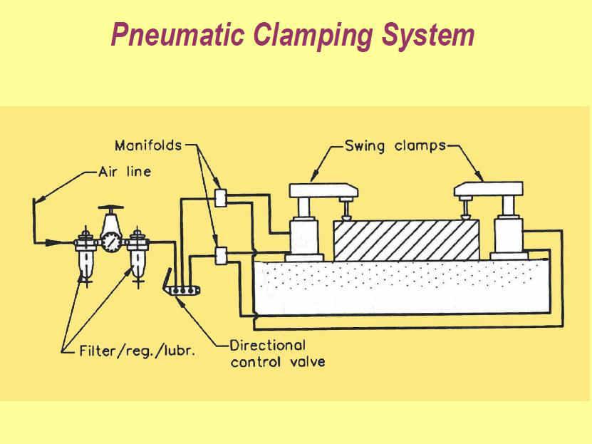
17 Power Driven Clamping Light duty clamps are used manually because small power is required to operate these clamps. Hand clamping leads to application of variable pressure, operators fatigue and more time consumed. The power driven clamping over comes the above mentioned problems of hand clamping. Power clamps are operated on the base of hydraulic or pneumatic power. Power clamps are high pressure clamping, these are quick acting, easily controllable, reliable and less time consuming. (Or) b) Discuss the following with suitable sketches: (i) Pneumatic clamps (ii) Plate clamps (iii) Quick action clamps [ CO1 L1 MAY/JUNE 2015] (i) Pneumatic clamps 17

18 (ii) Plate clamps 18

19 (iii) Quick action clamps Use of quick acting nut a typical of such nut and its application is visualized schematically in below figure. Cam clamping Quick clamping by cam is very effective and very simple in operation. Some popular methods and systems of clamping by cam are shown in below Fig.. The cam and screw type clamping system is used for clamping through some interior parts where other simple system will not have access 19
20 2.(a) (i) Describe the functions and advantages of jigs and fixtures. [ CO1 L2 MAY/JUNE 2015] Functions of Jigs and Fixtures: Functions of Jigs: 1. To locate the hole in the appropriate positions. 2. To clamp the work piece during drilling, reaming or tapping. 3. To guide the drills, reamers or tap into the proper position on the work piece. Functions of Fixtures: 1. To locate and position the work piece relative to the cutting tool. 2. To clamp the work piece during machining, welding, inspection or assembly. Advantages of Jigs and Fixtures: PRODUCTIVITY: 20
21 Jigs and fixtures increase the productivity by eliminating the individual marking, positioning and frequent checking. The operation time is also reduced due to increase in speed, feed and depth of cut because of high clamping rigidity. INTERCHANGEABILITY AND QUALITY: Jigs and fixtures facilitate the production of articles in large quantities with high degree of accuracy, uniform quality and interchangeability at a competitive cost. SKILL REDUCTION: There is no need for skillful setting of work on tool. Jigs and fixtures makes possible to employ unskilled or semi skilled machine operator to make savings in labour cost. COST REDUCTION: Higher production, reduction in scrap, easy assembly and savings in labour cost results in ultimate reduction in unit cost. (a) (ii) Explain briefly with neat sketch redundant location. [ CO1 L1 MAY/JUNE 2015] A duplicating or redundant location is said to be present when more than one locator is used to constraint a freedom; redundant location must be avoided. Another condition to avoid in workholder design is redundant, or duplicate, location. Redundant locators restrict the same degree of freedom more than once. The workpieces in Figure 3-15 show several examples. The part at (a) shows how a flat surface can be redundantly located. The part should be located on only one, not both, side surfaces. Since the sizes of parts can vary, within their tolerances, the likelihood of all parts resting simultaneously on both surfaces is remote. The example at (b) points out 21

22 the same problem with concentric diameters. Either diameter can locate the part, but not both. The example at (c) shows the difficulty with combining hole and surface location. Either locational method, locating from the holes or locating from the edges, works well if used alone. When the methods are used together, however, they cause a duplicate condition. The condition may result in parts that cannot be loaded or unloaded as intended. Always avoid redundant location. The simplest way to eliminate it is to check the shop print to find which workpiece feature is the reference feature. Often, the way a part is dimensioned indicates which surfaces or features are important. As shown in below Figure, since the part on the left is dimensioned in both directions from the underside of the flange, use this surface to position the part. The part shown to the right, however, is dimensioned from the bottom of the small diameter. This is the surface that should be used to locate the part. The best locating surfaces are often determined by the way that the part is dimensioned 22
![(Or) b) (i) Explain the working of hydraulic clamps. [ CO1 L1 MAY/JUNE 2015] b) (ii) Draw and explain briefly the different types of drill bushes.](/docs-images/91/106996596/images/23-0.jpg "[ CO1 L1 MAY/JUNE 2015] Jig Bushing: Sometimes the stiffness of the cutting tool may be in sufficient to perform certain machining operations.")
23 (Or) b) (i) Explain the working of hydraulic clamps. [ CO1 L1 MAY/JUNE 2015] b) (ii) Draw and explain briefly the different types of drill bushes. [ CO1 L1 MAY/JUNE 2015] Jig Bushing: Sometimes the stiffness of the cutting tool may be in sufficient to perform certain machining operations. Then to locate the tool relative to the work, use is made of guiding parts such as jigs bushing and templates. These must be precise, were resistance and changeable. Jig bushes are used in drilling and boring, a bush fits into the hole of the jig, through which the drill passes. The diameter of the bush depends on the diameter of the drill. Different type of bushes is spot welded or screwed with the jig. Headless type bushes are press fit into the hole of the job. Bushes are general made of a good grade of tool steel to insure hardening at a fairly no temperature and to lesson the danger of fire cracking. Sometime the bushes for guiding tools may be of cast iron. Hardened steel bushes are always preferable for guiding drills, reamers and taps etc. American standard bushes are classified in three categories. 1: press- fit wearing bushes 23

. Its replacement is simply by using a renewable bush. These are of the flanged types and sliding fit into the linear bush, which is installed press fitted into the jig plate.")
24 2: renewable wearing bushes 3: linear wearing bushes Types of bushes (tool guide/jig bushes): 1: Press fit wearing bushes: These bushes are used when little importance in put on accuracy or finish and tool used is a twist drill. These bushing are installed directly in the jig body and are used mainly for short protection. There are two design of press fit bushing: A> Plain or headless bush B> Headed or flanged bush 2: Renewable bushes: When the guide bushes requires periodic replacement (due to wear of the inside diameter of the bush). Its replacement is simply by using a renewable bush. These are of the flanged types and sliding fit into the linear bush, which is installed press fitted into the jig plate. The linear bush provides hardened wear resistance, mating surface to the renewable bush. The renewable bushes must be prevented from rotating or lifting with the drill. One common method is to use a retaining screw. 24
 [ CO1 L1 MAY/JUNE 2013 & 14] LOCATING PRINCIPLES To position the work piece w.r.t. to tool, to ensure precision in")
25 3: Linear bushes: These bushes are also known as master bushing, are permanently fixed to the jig body. These acts as guides for renewable type bushing. These bushes are be with or without head. 3. With suitable sketches explain any four important principles of location. (16 Marks) [ CO1 L1 MAY/JUNE 2013 & 14] LOCATING PRINCIPLES To position the work piece w.r.t. to tool, to ensure precision in machining Locating: dimensional and positional relationship b/w work piece and tool Locator: device to establish and maintain position of a part in a jig or fixture BASIC PRINCIPLES Positioning the locator Accuracy & tolerances Fool proofing Duplicate location Motion economy 1- Positioning the locators Locators should contact the work (preferably machines surface) on a solid and stable point: 25

26 This permits accurate placement of the part in the tool & ensures the repeatability of the jig and fixture They should be placed as far as possible: This permits the use of fewer locators Ensures complete contact over the locating surface 2- Accuracy and Tolerance The work piece itself determines the overall size of a locating element. locators must be made to suit the MMC (Maximum-Material Condition) of the area to be located. (The MMC of a feature is the size of the feature where is has the maximum amount ofmaterial). With external features, like shafts, the MMC is the largest size within the limits. With internal features, like holes, it is the smallest size within the limits. The main considerations are the size of the area to be located and the required clearance between the locator and the workpiece. Make the locating pin slightly smaller than the hole. Here the hole is specified as inch in diameter. Following the rule of MMC, the locator must fit the hole at its MMC of 0.5 inch. Allowing for a clearance between the pin and the hole, desired pin diameter is calculated at inch. 26
27 Tool tolerance should be between 20 and 50 percent of the part tolerance. 3- Fool proofing Ensures that the part fits into the tool in its correct position only. The simplest and most cost effective method is positioning a fool proof pin. 4- Duplicate Location A redundant location is said to be present when more than one locator is used to constraint a freedom; redundant location must be avoided. 5. Motion Economy It involves use of easy, quick and economic loading of work pieces. 27
28 4. Explain the various principles of clamping. (8 Marks) NOV/DEC2013 ] [ CO1 L1 clamping need to be strong and rigid enough to hold the blank firmly during machining clamping should be easy, quick and consistently adequate clamping should be such that it is not affected by vibration, chatter or heavy pressure the way of clamping and unclamping should not hinder loading and unloading the blank in the jig or fixture the clamp and clamping force must not damage or deform the workpiece clamping operation should be very simple and quick acting when the jig or fixture is to be used more frequently and for large volume of work clamps, which move by slide or slip or tend to do so during applying clamping forces, should be avoided clamping system should comprise of less number of parts for ease of design, operation and maintenance the wearing parts should be hard or hardened and also be easily replaceable clamping force should act on heavy part(s) and against supporting and locating surfaces clamping force should be away from the machining thrust forces clamping method should be fool proof and safe clamping must be reliable but also inexpensive 5. Sketch and explain any two mechanically actuated clamps. (8 Marks) [ CO1 L2 NOV/DEC 2012 & MAY/JUNE ] Different variety of clamps used with jigs and fixtures are classified into different categories are discussed here. Strap Clamp 28
29 This is also called edge clamp. This type clamping is done with the help of a lever pressure acting as a strap on the workpiece. Different types of strap clamps are discussed below. Heel Clamp The simple form of a heel clamp is shown in Figure 4.9. Rotation of the clamp in clockwise direction is prevented and it is allowed in anticlockwise direction. For releasing the workpiece the clamping nut is unscrewed. The free movements in anticlockwise direction takes place before un-securing the nut to release the workpiece. Bridge Clamp The bridge clamp is illustrated in Figure It applies more clamping pressure as compared to heel clamp. The clamping pressure experienced by the workpiece depends on the distances x and y marked in the Figure To release the workpiece the nut named as clamping nut is unscrewed. The spring lifts the lever to release the workpiece. 29
30 Edge Clamp or Side Clamp A side clamp is also known as edge clamp. In this case the surface to be machined is always clamped above the clamping device. This clamping device is recommended for fixed length workpiece. The clamping device is illustrated in Figure Releasing and clamping of the workpiece can be accomplished by unscrewing and screwing of the clamping nut respectively. Screw Clamp 30
31 The screw clamp is illustrated in Figure It is also known as clamp screw. This clamping applies pressure directly on the side faces of the workpiece. There is a floating pad at their end to serve the following purposes: (a) It prevents displacement of workpiece and slip. (b) It prevents denting of clamping area of workpiece. (c) The available cushion prevents deflection of screw. In addition to the above there are some disadvantages associated with this method. The clamping pressure largely depends on the workpiece, it varies from one workpiece to other. It is more time consuming and more efforts are required. Latch Clamp Latch clamps are used to clamp the workpiece, the clamping system is normally locked with the help of a latch provided. To unload the workpiece the tail end of the latch is pushed that causes the leaf to swung open, so releasing the workpiece. Here time consumed in loading and unloading is very less as no screw is tightened but clamping pressure is not so high as in other clamping devices. Life of this type of clamping device is small. Equalizing Clamps Equalizing clamp is illustrated in Figure It is recommended to apply equal pressure on the two faces of the work. The pressure applied can be varied by tightened or loosening the screw provided for the purpose. 31
32 Power Driven Clamping Light duty clamps are used manually because small power is required to operate these clamps. Hand clamping leads to application of variable pressure, operators fatigue and more time consumed. The power driven clamping over comes the above mentioned problems of hand clamping. Power clamps are operated on the base of hydraulic or pneumatic power. Power clamps are high pressure clamping, these are quick acting, easily controllable, reliable and less time consuming. 6. What are the main objectives to be considered while designing jigs and fixtures? (8 Marks) ([ CO1 L1 NOV/DEC2009 ] The main objectives to be considered while designing jigs and fixtures is to lower manufacturing costs while maintaining quality and increased production Tool Efficiency Quality Low cost More production Tool life Foolproof Safety operation 32
33 7. Explain briefly the main elements of jigs and fixtures. (8 Marks) [ CO1 L1 NOV/DEC2009 ] Various elements of jigs and fixtures and their details are follows. 1: Body 2: Locating devices 3: Clamping devices 4: Tool guide (jigs bushing) 1: Body: The jig body is generally made of cost iron by casting process or fabricated by welding together various slabs and bars of mild steel. It may be heat treated to relief the stresses. Body is the most prominent feature of the jig. Its main purpose is to support and house the job. The various jig body are follows: (A):Plane Type Jig: Plane type jig is the simplest type, it is used when plane holes are to be drilled. It has either drill bushes for guiding the tools or the holes without bushes. (B): Channel Type Jig: Channel type is made up from standard steel channel section. (C): Box type Jig: Box type jig is used where a component requires drilling in more than one plane and the jig is to be provided with on equilant number of drill bush plates. One side of the box is fitted with a lid which can be opened for inserting the component and for unloading it. It should be made as light as possible. (D): The Built Up Jig: The built up jig used dowels and screws for fabricating member welded type. Standard steel sections are used in it for the limited numbers of details, which are secured by means of screws and dowels, the locating pins and the blocks are positioned so that the greatest dimensional variation of the work piece may be accommodated. (E): Leaf Type Jig: Leaf type jig is simple made from a block of steel fitted with two adjustable locating screws and a spring loaded plunger. It is used in case of measured large components where it may be both unnecessary and construct a jig to hold the complete component, where madding is purely confined to a local section of the work piece. 2:Locating Devices 33

34 The pins of various design and made of hardened steel are the most common locating devices used to locate a work piece in a jig or fixture. The shank of the pin is press fitted or driven into the body of jig or fixture. The locating diameter of the pin is made larger than the shank to prevent it from being forced into the jig or fixture body due to the weight of the work piece or cutting forces. Depending upon the mutual relation between the work piece and the pin. The pin may be classify as follows: (A): Locating Pins: When reamed or finally finished holes are available in work piece, these can be used for locating purpose of the manner as shown, these are two types of locating pins: Conical locating pins Cylindrical locating pins (B): Support Locating Pins: With these pins (also known as rest pins) buttons or pads the work piece with flat surfaces supported at convenient. In the fixed support pins the locating face is either ground flat or curved. Support pins with flat head are usually employed and provided location and support to machine surface, because more contact area is available during location. It would insure accurate and stable location. The spherical head or round head rest buttons are used for supporting rough surfaces (un machined and cast surfaces) because they provide a point support which may be stable under these circumstances. Adjustable type support pins are used for work piece whose dimension can vary. For example sand casting, forging or unmachined faces. 34


35 (C): Jack Pins: Jack pins or spring pins are also used to locate the work piece whose dimension are subjected to variation. The pin is allow to come up under spring pressure or conversely is pressed down by the work piece. When the location of the work piece is secured the pin is locked in this position by means of locking screw. 3: Clamping devices: If the work piece can not be restrained by the locating devices or elements, it become necessary to clamp the work piece in jig or fixture body. The most common example of clamping devices is bench vice. The purpose of the clamping is to exert a pressure to press a work piece against the locating surfaces and hold it there in a position to the cutting forces. In bench vice the movable jaw of the vice exert force on the work piece, their by holding it in correct position of location in the fixed jaw of the vice. The commonly used clamping devices are follows: 35
: Hook Bolt Clamp: This is very simple clamping device and is only suitable for light work and")
: Bridge Clamp: It is very simple and reliable clamping device.")
36 (A): Clamping Screws: Clamping screws are used for light clamping. Clamping screws are shown in fig. (B): Hook Bolt Clamp: This is very simple clamping device and is only suitable for light work and where usual tip of the clamp is inconvenient. The typical hook bolt clamp is shown. (C): Bridge Clamp: It is very simple and reliable clamping device. The clamping force is applied by spring loaded nut. 36

: Swinging Strap(Latch Clamp): This is a special type of clamp which provides a means of intry for loading and unloading the work piece.")
37 (D): Heel Clamp: These consist of a rusted plate, center stud and heel. This trap should be strengthen at the point where the hole for the stud is cut out, by increasing the thickness around the hole. The design differ from simple bridge clamp in that a heel is provided at the outer end of the clamp to guide its sliding motion for loading and unloading the work piece. (E): Swinging Strap(Latch Clamp): This is a special type of clamp which provides a means of intry for loading and unloading the work piece. For this the strap(latch or lid) can be swing out from the work piece. The typical swing strap or latch clamp is shown in figure. 37


38 (F): C-Clamp: To unload the work piece, the locking nut is unscrewed by giving it about one turn and this releases the c- clamp. When the clamp is removed or swing away the work piece can freely pass over the nut. To reverse procedure is adopted for loading the work piece. 4: Tool Guide or Jig Bushing: Sometimes the stiffness of the cutting tool may be in sufficient to perform certain machining operations. Then to locate the tool relative to the work, use is made of guiding parts such as jigs bushing and templates. These must be precise, were resistance and changeable. Jig bushes are used in drilling and boring, a bush fits into the hole of the jig, through which the drill passes. The diameter of the bush depends on the diameter of the drill. Different type of bushes is spot welded or screwed with the jig. Headless type bushes are press fit into the hole of the job. Bushes are general made of a good grade of tool steel to insure hardening at a fairly no temperature and to lesson the danger of fire 38
39 cracking. Sometime the bushes for guiding tools may be of cast iron. Hardened steel bushes are always preferable for guiding drills, reamers and taps etc. American standard bushes are classified in three categories. 1: press- fit wearing bushes 2: renewable wearing bushes 3: linear wearing bushes 8. Explain the following clamps. a. Clamp with heel pins (3 Marks) b. Two point clamps (3 Marks) c. Three point clamps (3 Marks) d. Pressure Pads (3 Marks) e. Cam clamps (4 Marks) [ CO1 L2 NOV/DEC2009 ] a. Heel Clamp The simple form of a heel clamp is shown in Figure 4.9. Rotation of the clamp in clockwise direction is prevented and it is allowed in anticlockwise direction. For releasing the workpiece the clamping nut is unscrewed. The free movements in anticlockwise direction takes place before un-securing the nut to release the workpiece. b.two point clamps This has a quick release action, when the nut is released the clamp becomes loose. 39


40 d.pressure Pads Used above or below the workpiece depending on size and shape of workpiece Necessary when workpiece contains sharp corners or irregular surfaces Also used to absorb shocks Pressure for pads applied by springs,air or hydraulics Urethane pads require less space than springs since they withstand greater pressure with less deflection compared to springs e. Cam clamping: 40
41 Quick clamping by cam is very effective and very simple in operation. Some popular methods and systems of clamping by cam are shown in Fig The cam and screw type clamping system is used for clamping through some interior parts where other simple system will not have access. 9. Explain different locating methods. (12 Marks) [ CO1 L1 NOV/DEC2012 & 13 ] There are different methods used for location of a work. The locating arrangement should be decided after studying the type of work, type of operation, degree of accuracy required. Volume of mass production to be done also mattes a lot. Different locating methods are described below. Flat Locator Flat locators are used for location of flat machined surfaces of the component. Three different examples which can be served as a general principle of location are described here for flat locators. These examples are illustrated in Figure


42 A flat surface locator can be used as shown in first figure. In this case an undercut is provided at the bottom where two perpendicular surfaces intersect each other. This is made for swarf clearance. The middle figure shows flat headed button type locator. There is no need to made undercut for swarf clearance. The button can be adjusted to decide very fine location of the workpiece. There can be a vertical button support as shown in third figure, which is a better arrangement due to its capacity to bear end load and there is a provision for swarf clearance automatically. Cylindrical Locators A cylindrical locator is shown in Figure 4.4. It is used for locating components having drilled holes. The cylindrical component to be located is gripped by a cylindrical locator fitted to the jig body and inserted in the drilled hole of the component. The face of the jig body around the locator is undercut to provide space for swarf clearance. Conical Locator 42
43 A conical locator is illustrated in Figure 4.5. This is used for locating the workpieces having cylindrical hole in the workpiece. The workpiece is found located by supporting it over the conical locator inserted into the drilled hole of the workpiece. A conical locator is considered as superior as it has a capacity to accommodate a slight variation in the hole diameter of the component without affecting the accuracy of location. Degree of freedom along z-axis can also be restrained by putting a template over the workpiece with the help of screws. Jack Pin Locator Jack pin locator is used for supporting rough workpieces from the button as shown in Figure 4.6. Height of the jack pin is adjustable to accommodate the workpieces having variation in their surface texture. So this is a suitable method to accommodate the components which are rough and un-machined. Drill Bush Locator 43
44 The drill bush locator is illustrated in Figure 4.7. It is used for holding and locating the cylindrical workpieces. The bush has conical opening for locating purpose and it is sometimes screwed on the jig s body for the adjustment of height of the work. Vee Locators This is quick and effective method of locating the workpiece with desired level of accuracy. This is used for locating the circular and semi-circular type of workpieces as shown in Figure 4.8. The main part of locating device is Vee shaped block which is normally fixed to the jig. This locator can be of two types fixed Vee locator and adjustable Vee locator. The fixed type locator is normally fixed on the jig and adjustable locator can be moved axially to provide proper grip of Vee band to the workpiece. 10. Explain about the different materials used for the design of jigs and fixtures (16 Marks) [ CO1 L2 NOV/DEC2013 ] 44
45 Jigs and Fixtures are made of variety of materials, some of which can be hardened to resist wear. Materials generally used: 1. High speed Steel: Cutting tools like drills, reamers and milling cutters. 2. Die steels: Used for press tools, contain 1% carbon, 0.5 to 1% tungsten and less quantities of silicon and manganese. 3. Carbon steels: Used for standard cutting tools. 4. Collet steels: Spring steels containing 1% carbon, 0.5% manganese and less of silicon. 5. Non shrinking tool steels: High carbon or high chromium Very little distortion during heat treatment. Used widely for fine, intricate press tools. 6. Nickel chrome steels: Used for gears. 7. High tensile steels: Used for fasteners like high tensile screws 8. Mild steel: Used in most part of Jigs and Fixtures Cheapest material Contains less than 0.3% carbon 9. Cast Iron: Used for odd shapes to some machining and laborious fabrication CI usage requires a pattern for casting Contains more than 2% carbon Has self lubricating properties Can withstand vibrations and suitable for base 10. Nylon and Fiber: Used for soft lining for clamps to damage to workpiece due to clamping pressure 11. Phospher bronze: used for nuts as have high tensile strength Used for nuts of the lead screw 11. List out the advantages and disadvantages of jigs and fixtures (8 Marks) [ CO1 L1 NOV/DEC2012 ] PRODUCTIVITY: Jigs and fixtures increase the productivity by eliminating the individual marking, positioning and frequent checking. The operation time is also reduced due to increase in speed, feed and depth of cut because of high clamping rigidity. INTERCHANGEABILITY AND QUALITY: 45
46 Jigs and fixtures facilitate the production of articles in large quantities with high degree of accuracy, uniform quality and interchangeability at a competitive cost. SKILL REDUCTION: There is no need for skillful setting of work on tool. Jigs and fixtures makes possible to employ unskilled or semi skilled machine operator to make savings in labour cost. COST REDUCTION: Higher production, reduction in scrap, easy assembly and savings in labour cost results in ultimate reduction in unit cost. 46
47 UNIT II JIGS AND FIXTURES Design and development of jigs and fixtures for given component- Types of Jigs Post, Turnover, Channel, latch, box, pot, angular post jigs Indexing jigs General principles of milling, Lathe, boring, broaching and grinding fixtures Assembly, Inspection and Welding fixtures Modular fixturing systems- Quick change fixtures. PART A 1. V blocks are widely used in milling fixtures. State the reasons. [ CO2 L2 MAY/JUNE 2016 ] V blocks are widely used in milling fixtures because most of the components used in milling fixtures were cylindrical and circular components only. 2. How does a setting block in a milling fixture differ from a guide bush of a jig? (EVEN 2015) To reduce the setting time of the milling cutter with respect to the work piece, the fixture is provided with the setting block. Guide or drill bushes are used to guide drills, reamers and other cutting tools into the proper position on the work piece. 3.Define the term: liner bushes. (ODD 2015) Liner bushes, also known as master bushings are permanently fixed into the jig body. Liner bushings are available in head or headless types and are pressed into the jig plate. The liner bushings are hardened and so they provide only a little chance of affecting the accuracy of the tool by changing the bushings. 4. What forces does a drill bit exert on a work piece? (ODD 2015) Torsional force exerted on the work piece 5. What is the use of channel jig? (EVEN 2014) 47
48 Channel jig was used standard channel section material and workpiece is fitted within the channel. For drilling in more than one surface, Complicated and expensive places also used. 6. Distinguish between a pot jig and a box jig. (ODD 2007) In a pot jig, holes are drilled in hollow cylindrical components having flanges with relatively smaller outside and inside diameters but holes can be drilled on more than face using box jigs. 7. Sketch the channel jig. (EVEN-04, ODD 06 & ODD 2013) 8. What is the use of indexing jig? (ODD -2013) Indexing jigs are used to drill series of holes in a circle on the face of a workpiece. 9. What is the function of jig bushes? Drill bushes are used to guide drills, reamers and other cutting tools into the proper position on the work piece. 10. What are the two types of press fit bushes? a. Plain or headless bushes b. Flanged or headed bushes 48
49 11. Distinguish between the channel and box jigs. (ODD 2008) In channel jigs, holes are drilled only in face but holes can be drilled on more than face using box jigs. 12. What are the different types of jigs? a. Plate jigs c. Channel jig e. Angle plate jig 13. b. Latch jig d. Box jig f. Pot jig Define sandwich jig. These jigs are a form of plate jig with a back plate. This type of jig is ideal for thin or soft parts that could bend or wrap in another style of jig. Here again, the use of buildings is determined by the number of parts to be made. 14. What are the standard work holding devices in lathe? a. Chucks c. Face plate 15. Mention any four essential features made on milling fixtures. a. Base c. Setting block 16. b. Collets d. Mandrels b. Tenon strips d. Locating elements List out the various locators used in fixtures. a. Cylindrical locating pin b. Diamond pin locator c. Screw and dowels 17. Name any four essential features of a milling fixture. a. Base b. Locating elements c. Setting elements d. Tenon strips e. Clamping element 18. What devices are mainly used to assemble modular elements? 49
50 Modular fixturing is a work holding system which uses a series of reusable standard components to build a wide variety of special purpose work holding devices. These types of fixtures are assembled with a variety of standard tooling plates, supports, locating elements, clamping devices and similar units. 19. What are the important elements of inspection fixtures? a. Locating element b. Clamping element c. Gauging element d. Auxiliary element 20. What are the two types of inspection fixtures? a. In-process inspection fixtures b. Off-line inspection fixtures 21. State the use of grinding fixtures. Several different forms of fixtures are used on grinding machines to locate, hold and support the work piece during the operations. 22. What are boring fixtures? How do you classify them? This fixture which is used for cutting internal key-ways in pulleys, gears, sprockets, etc is known as key way broaching fixture 23. What are the various machine tools used for boring? a. Lathes b. Drill presses c. Milling machine d. Jig boring machine e. Vertical or horizontal boring mills 24. State the classification of boring bars. a. Stub bar 25. b. Single-piloted bar What are the different types of broaching operation? a. Keyway broaching 26. c. Double-piloted bar b. Hole broaching c. Gear broaching What are fixtures? 50

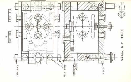
51 Some type of tooling used in positioning parts relative to each other for fabricating purposes are commonly referred to as fixtures. 27. When slip bushes are used? Slip bushes are mainly used when a hole in the work piece requires two operations. Ex: performing both drilling and reaming in a same jig plate. 28. What is the use of tack welding fixture? Tack welding fixtures are used to locate the components of an element in their correct relationship with proper clamps while a welder tacks them together prior to their final welding. PART B 33.(a) Explain with neat sketch the working of box jig. (EVEN 2015) Box jigs, or tumble jigs, usually totally surround the part. This style of jig allows the part to be completely machined on every surface without the need to reposition the work in the jig. 51
52 (or) (b) Design a drill jig for drilling 4 holes in the following component. (EVEN 2015) 52
53 53
54 54
55 55
56 3.(a) Discuss in detail : (i) Linear Indexing (ii) Rotary Indexing (iii) Important accessories of Jigs and Fixtures (ODD 2015) 56
57 57
 Facing fixture for milling (iii) A welding fixture (ODD 2015)")
58 (Or) b) Discuss the following in detail with suitable illustrations: (i) Plate type Jigs for drilling (ii) Facing fixture for milling (iii) A welding fixture (ODD 2015) 58
59 (i) Plate type Jigs for drilling Plate Type Jig Plate jigs are similar to templates. The only difference is that plate jigs have builtin clamps to hold the work. These jigs can also be made with or without bushings, depending on the number of parts to be made. Plate jigs are sometimes made with legs to raise the jig off the table for large work. This style is called a table jig. (ii) Facing fixture for milling 59
60 60
61 MILLING FIXTURE: A Milling Fixture is located accurately on the machine table and then bolted in position; the table is positioned relative to the cutter or cutters with the aid of the Setting Block. The work piece is located on the Fixture base and then clamped in position. The cutter is not guided during cutting. 61
62 The location and clamping systems are similar to those used for drill jigs, but as the cutting forces are high, interrupted, and tend to lift the work piece, the clamping forces must be big; hexagonal nuts are usually used to clamp the work piece rather than hand nuts. The details that are peculiar to Milling Fixtures are the Setting Block and the Location Tenons. Setting Block : The setting block as shown in the figure, is located relative to the fixture location system and retained in position by screws; it has two hardened setting faces, so that the table can be positioned both horizontally and vertically (note that the table is located from one side of the cutter only). The table setting is done with a 0.25 mm feeler between the cutter and the setting face so that the block will not be damaged by the cutter during machining. The setting block is positioned so that the cutter is between the vertical face of the block and the operator during setting; this arrangement gives maximum convenience for the operator during setting. Tenons : The two Tenons (as shown in the figure) are made from case hardened steel and are located on the underside of the fixture base; these two tenons sit in one of the tee slots that run along the length of the machine table so that the fixture is located relative to the table feed; the two Tenons should be as far apart as possible, to produce maximum accuracy. The Fixture is bolted to the table by two or four tee bolts that are placed in the tee slots (these bolts are not called up as part of the fixture). (iii) A welding fixture Welding fixtures are normally designed to hold and support the various components (workpieces) to be welded. It is necessary to support them in a proper location which is capable of preventing distortions in workpieces during welding. For this the locating elements need to be placed carefully, clamping has to be light but firm, placement of clamping elements has to be clear of the welding area and the fixture has to be quite stable and rigid to withstand the welding stresses. There is no limit of designing a welding fixture. Its design depends on and driven by the hard facts that are what you want, and how to overcome the problems appearing with the current fixture. Keeping the defect free fast production rate as major target. The famous saying Need is the mother of invention hold perfectly true in case of welding fixture design. In many cases, most preferred practice is to first tack weld the structure by holding it in a welding jig and then transfers it to a holding fixture for full welding. This helps in reducing the chances of distortion considerably and also the fixture is subjected to lesser stresses. An example of a welding fixture is illustrated in Figure. The fixture is equipped with a rotatable clamp at variable speeds. There is an adjustable torch holder which can be 62
63 moved to the right position in the limited space. This fixture is recommended for the welding on circular shaped objects. 1. With suitable sketches explain the uses of plate and channel jigs. (8+8 Marks) EVEN-2008) Plate Type Jig Plate jigs are similar to templates. The only difference is that plate jigs have builtin clamps to hold the work. These jigs can also be made with or without bushings, depending on the number of parts to be made. Plate jigs are sometimes made with legs to raise the jig off the table for large work. This style is called a table jig. Channel Jig Channel jigs are the simplest form of box jig. The work is held between two sides and machined from the third side. In some cases, where jig feet are used, the work can be machined on three sides. 63

 ((EVEN -2008)")
64 2. Explain the use of turnover jig with neat diagram. (16Marks) ((EVEN -2008) ((EVEN -2013) ) ((EVEN -2014) 64
 Grinding fixture ( ODD-2013)")
65 3. Explain the following with neat sketches: (i) Milling fixture (ii) Grinding fixture ( ODD-2013) 65
66 MILLING FIXTURE: A Milling Fixture is located accurately on the machine table and then bolted in position; the table is positioned relative to the cutter or cutters with the aid of the Setting Block. The work piece is located on the Fixture base and then clamped in position. The cutter is not guided during cutting. The location and clamping systems are similar to those used for drill jigs, but as the cutting forces are high, interrupted, and tend to lift the work piece, the clamping forces must be big; hexagonal nuts are usually used to clamp the work piece rather than hand nuts. The details that are peculiar to Milling Fixtures are the Setting Block and the Location Tenons. Setting Block : The setting block as shown in the figure, is located relative to the fixture location system and retained in position by screws; it has two hardened setting faces, so that the table can be positioned both horizontally and vertically (note that the table is located from one side of the cutter only). The table setting is done with a 0.25 mm feeler between the cutter and the setting face so that the block will not be damaged by the cutter during machining. The setting block is positioned so that the cutter is between the vertical face of the block and the operator during setting; this arrangement gives maximum convenience for the operator during setting. Tenons : The two Tenons (as shown in the figure) are made from case hardened steel and are located on the underside of the fixture base; these two tenons sit in one of the tee slots that run along the length of the machine table so that the fixture is located relative to the table feed; the two Tenons should be as far apart as possible, to produce maximum accuracy. The Fixture is bolted to the table by two or four tee bolts that are placed in the tee slots (these bolts are not called up as part of the fixture). Grinding Fixture The standard magnetic tables are used to rest workpiece such that resting surface will be parallel to the surface to be ground. However, for light workpiece with lesser resting area, the resting area tends to tilt and fly off the magnetic table due to high speed of grinding wheel and due to high feed, also. Hence, it is necessary to provide additional support by nesting the workpiece. This can be done by placing the solid plates around the workpiece as shown in Figure 4.8. The nest plates are held firmly by the magnetic force of table with more weight and more resting area. The nest plates surround the 66
67 workpiece from outside and arrest its movement in the horizontal plane. Thus, this arrangement will help in preventing it from flying off and tilting due to high speed and feed in grinding operation. The maximum possible area of magnetic table should be utilized to grind as many workpieces as possible in a single batch. 67
68 4. Explain about Pot Jig & Post Jig Pot Type Jig This jig is used for drilling holes in hallow cylindrical components having smaller size. Here the body of the jig is like a pot that is used to accommodate the 68

69 workpiece comfortably. Location on the inside surface of the component is provided by the clamp projecting from the bush plate located over the top of the workpieces. 69

70 5. Explain about Box Jig Box jigs, or tumble jigs, usually totally surround the part. 70
71 This style of jig allows the part to be completely machined on every surface without the need to reposition the work in the jig. 71
72 72
73 6. Design a drill jig for drilling an oil hole of size 3mm for the given job as in figure. ((EVEN -2010) 73
74 74
75 7. Design and draw jig for mild steel component shown in figure to drill 4 holes of 5 mm diameter at 70 P.C.D ( ODD 2013) 75
76 76
77 77
78 UNIT III PRESS WORKING TERMINOLOGIES AND ELEMENTS OF CUTTING Press Working Terminologies - operations Types of presses press accessories Computation of press capacity Strip layout Material Utilization Shearing action Clearances Press Work Materials Center of pressure- Design of various elements of dies Die Block Punch holder, Die set, guide plates Stops Strippers Pilots Selection of Standard parts Design & preparation of four standard views of simple blanking, piercing, compound and progressive dies. PART A 1.you compute the diameter of blank required for drawing a straight sided cylindrical cup of diameter d and height h? (EVEN 2015) Blank diameter When is 20 or more -0.5r -r When 15< < 20 When 10< < 15 When < What is mean by spring back? (EVEN 2015) At the end of a metal working operation, when the pressure on the metal is released, there is an elastic recovery by the material and the total deformation will get reduced a little. This phenomenon is called as spring back. 3. Compare the compound and progressive dies. (ODD 2015) Compound die It performs more than one operation at a time in each station. Tonnage requirement is more. Complicated in design and construction of die set. It ensures more accuracy. More expensive to construct and repair. Progressive die It performs one operation at a time in each station. Tonnage requirement is less. Simple in design and construction of die set. It ensures less accuracy position. Less expensive to construct and repair. 4. What is stripper? (ODD 2015) 78
79 It is a plate which is used to strip the metal from a cutting or non-cutting punch or die. It may also guide the sheet. 5. Which is called as press tool? (ODD 2014) Press tool is a metal forming machine tool used to shape or cut metal by applying force. 6. Define Centre of Pressure. (ODD 2014) It is the centre of gravity of the line i.e., the perimeter of the blank. The press tool is designed that the centre of pressure will lie on the axis of press ram when tool is mounted on the press. 7. List the difference between a press tool and a machine tool. (EVEN 2014) Press tool Machine tool Press tool is a metal forming machine tool Machine tools employ some sort used to shape or cut metal by applying force. of tool that does the cutting or shaping. Press tools are commonly used in hydraulic, A machine tool is a machine for pneumatic, and mechanical presses to shaping or machining metal or produce components at high volumes. other rigid materials. Generally press tools are categorized by the Usually by cutting, boring, types of operation performed using the tool, grinding, shearing, or other such as blanking, piercing, bending, forming, forms of deformation. forging, trimming etc. 8. What are the different types of strip layouts available for better material utilization? (EVEN 2014) Line layout Nested layout Circular blank layout Distinguish between a blanking die and a bending die. [ODD 2007] Blanking die Bending die 79
80 It is cutting operation. A permanent deformation is produced beyond it plastic range to cutout the required part. Shear is provided either on die or punch. The left out portion is considered as waste. Tonnage requirement is more. 10. It is a forming operation. It is a localized permanent deformation within the plastic range No shear is provided either on die or punch. The left out portion is the required part. Tonnage requirement is less. Differentiate between punching and piercing operation. [EVEN 2006] Punching Piercing Punching is the operation of It is the operation of producing the hole making holes regardless of shape on the work piece by a pointed and well and size designed punch. The design of punch, shear on the The design of punch, shear on the punch and clearance on die do punch and clearance on die are not play as a main role. considered as main elements to ensure the perfect piercing 11. Classify sheet metal operations. Cutting operations Forming operations How is the cutting operation carried out? The work piece is stressed beyond its ultimate strength and cutoff into two pieces. 13. How is forming operation carried out? In a forming process, the stresses are below the ultimate strength of the metal. 14. List out the various cutting operations Blanking Punching or piercing Shearing Parting off Notching Trimming 80
81 7. Shaving 8. Perforating 9. Slitting 10. Lancing. 15. Distinguish between blanking and piercing 16. Blanking Piercing The cutout portion is the required The cut portion is considered as part. waste. The left out portion is considered as The left out portion is the required waste. part. Die is made to exact size. Punch is made to exact size. Clearance is provided on the punch Clearance is provided on the die and and made smaller in size. made bigger in size. State any four advantages of press working Material economy High productivity Use of unskilled labor High degree of precision. List out the press working terminology. 1. Base 2. Bolster plate 3. Die holder 4. Die 5. Stripper 6. Punch 7. Back up plate 8. Guide post or guide pin 9. Pit man 18. What are the types of presses according to position of frame? 1. Inclinable press 2. Vertical press 3. Horizontal press 4. Inclined press. 19. Classify presses according to the mechanism used for applying power to ram Crank Toggle Eccentric 81
82 Cam Screw Rack and pinion Hydraulic Pneumatic. 20. Mention any four important factors to be considered while selecting a press. Force required to be cut the metal Die space Stroke length Shut height. 21. Name some types of forming operations. 22. Bending Drawing Sequeezing Embossing. What is the main difference between inclined presses and inclinable presses? Inclined Press Inclinable Press The frame of the press itself is inclined at an angle for easy discharge of work piece and scrap from the press. The whole press can be used both in vertical as well as inclined positions. 23. List out the main parts of a power press. [ODD 2008] Piston-cylinder arrangement Connecting rod Storage device Pipe lines What is the use of clutch in a power press? [EVEN 2008] A clutch is used in a power press to control vary the speed of cutting and forming operations. How will you select the proper material for press tools? [ODD 2008] Hardness Compressive strength Bending strength 82
83 Toughness What factors should be considered for selecting an appropriate press for a given job? [EVEN 2009] Force required to be cut the metal Die space Size and type of die Stroke length Method of feeding and size of sheet blank Shut height Type of operation Speed of operation. 27. What is the purpose of the sit ear angle found on a punch or die? [ODD 2007] The shear angle helps to reduce the shocks to the press and smoothen the cutting operation. 28. What is meant by clearance? Why is it important in shearing operation? [ODD 2007] Clearance is the intentional space between the punch cutting edge and die cutting edge. It is important in shearing to cut a sheet metal to deform by a shear failure in order to make various contours from the metallic sheet. 29. What are the effects of inadequate clearance and excessive clearance upon die-cut metals? [ODD & EVEN 2008] Inadequate clearance Excessive clearance: It does not allow a clean break but It allows a large edge radius and excessive partial break occurs. It is also plastic deformation. Large bums are present at called as secondary shear. the break edge and the break is not smooth. 30. Find die clearance range for shearing a 2 mm thick aluminum sheet. (EVEN 2009) Die clearance = 3% of metal thickness Die clearance = 0.03x2 = 0.06 mm 83
84 31. Mention the methods of reducing cutting forces in piercing operation. (EVEN 2007) Double shear can be provided in the punch Stepped punches can be used. 32. Distinguish between a compound die and a combination die. (EVEN 2009) Combination die Compound die It performs more than one operation It also performs more than one at a time in the same station. operation at a time but in each station. Tonnage requirement is less. Tonnage requirement is more. Maintenance will lead to idle of the During maintenance, one station at die due to break down. least can work. N number of components can be N number of components can be made with N strokes of die. made with N+1 strokes of die. 33. What is a progressive die? When should a progressive die be used? [ODD 2007 & EVEN 2008] 34. A die which is used to perform two or more operations at different stages every time when the ram descends is called progressive die. It is mainly used where accuracy of the products is maintained. Differentiate progressive dies with compound dies. 35. Progressive die Compound die It performs one operation at a time in It also performs more than the each station. operation at a time but in station. Tonnage requirement is less. Tonnage requirement is more. Simple in design and construction of Complicated in design die set. construction of die set. It ensures less accuracy position. It ensures more accuracy. Less expensive to construct and More expensive to construct repair. repair. What is called die block? one each and and The die block with cutting edge is the female half of the two mating tools. 36. Explain the function of bolster plate in press tool. (EVEN 2006) The bolster plate is the thick plate mounted on the base. It is used for locating and supporting the die assembly. It is usually 5 to 12.5mm thick plate. 84
85 37. State the various functions of a bolster plate. It provides attachment holes for the dies rather than drilling these holes in the press bed. It supports the die shoe, when it is located over a large hole in the press bed. It provides chutes for ejecting parts or scrap out the sides of the press. It takes up space in the press, when the press shut height is too great for the die shut height. 38. What is the function of a stripper? When should a spring-load stripper be used? ( ODD, EVEN 2005 & EVEN 2009) The prime function of the 'stripper' or' 'stripper plate' is to remove the stock from the punch after blanking or piercing operation. Spring -load stripper are used where very accurate blanks are needed and when very thin material is to be punched. 39. Compare fixed stripper and spring loaded stripper. Fixed stripper Spring loaded stripper It is simple in construction. It is complicated in construction. It does not apply any hold down It applies hold down pressure due to pressure. springs. It is mainly used for strip sheet metal It is mainly used for coiled sheet metal where feeding the sheet fixed. where feeding of spring loaded. The sheet is done by feed roll. It is used for very large stripping It is used for moderate spring force. force. 40. What is the purpose of pilot? [ODD 2004 & EVEN 2006] Pilot is a locating pin chamfered on the front end to facilitate catching and entering the work piece. PART B (a) (i) Write short notes on: Die Block; Punch holder; Guide plates. (ODD 2015) Die Block It is the block or a plate which contains the die cavity. 85

86 The die block size essentially depends on the work piece size and stock thickness. Though sometimes, the type of blank contour and the type of die may also influence the choice of die block size. A number of thumb rules are available which are essentially based on practical experience. The die block should be able to withstand the impact of the punch striking the material. The value of A should be 1.25 times the die thickness for smaller dies and 1.5 to 2.0 times for larger dies. 86

87 Punch Plate The punch plate or punch retainer fits closely over the body of the punch and holds it in proper relative position. (Or) (b) (i) Based on what criteria, press tools are selected? Force required to be cut the metal Die space Size and type of die Stroke length Method of feeding and size of sheet blank Shut height Type of operation Speed of operation 13.(a) (i) Write short notes on Types of Die Sets. Die sets are available in different sizes and styles. The commonly used the sets are of following types: Back-pin die set In this die set the pins are at the back of set, leaving a clear space for hand feeding blanks for second operations The good view of moving parts and freedom from obstructing pins and bushings also aids the operator when feeding from left to right. Centre-pin type 87
88 This set is used when load is too heavy and the feed is from the front. In this guide pins are in alignment with the load along the transverse center line of the set leaving the front clear but preventing end feeding either by hand or automatically. Diagonal pin It is used when load is very heavy and feeding is required. In this set one of the pins is placed at the front of set thus avoiding the overhang of the back pin type by having the load in alignment with the pins along a diagonal line and leaving the ends clear for feeding. For round work pieces especially for coming and shaving operations round die sets with pins at the back or along the Centre can be used to advantage. Dowels and screws Dowels and screws used in blanking and piercing dies should be located diagonally across from each other and as far apart as possible to increase location accuracy. All dowels and screws should be located at a distance ranging from 1.5 to 2 times their diameter from the component edge. They should be placed near the outer edge of die block as far as possible. Some of the characteristic features of screws and dowels used are as follows A minimum of one cap screw and two dowels are necessary to position and hold die component in place. More cap screws may be used for larger components but two and only two dowels should be used for positioning. Dowels should be located as far apart as possible to increase location accuracy. Screws and dowels should be located at 1.5 to 2 times their diameter from the component edge. The effective thread depth for screws should be 1.5 times to 2 times the screw diameter. Usually 9 to 10 mm screws are used on die components up to 150mm square. Heavy die Components are usually secured. With 12 mm to 16 mm diameter screws, dowel and screws diameter should be same. Cap screws used to secure die blocks should be placed in counter bored holes so that screw head is 3 to 4 mm deeper in the hole. This is provided to allow additional material for die grinding. (ii)die Block The various dimensions of the die block are calculated as follows Dies must be adequately supported on a flat die plate or die plate or die holder (shoe). 88
89 Two and only two dowels should be provided in each block or element that requires accurate and permanent positioning. They should be located as far apart as possible for maximum locating effect usually near diagonally opposite corners. Two or more screws should be used depending on the size of die block. Where p = Blanking perimeter. A grinding allowance up to 3 mm to 5 mm should be added to calculate die thickness. There should be minimum of 30 mm margin around the opening in the die block. Die block should never be thinner than 7 to 10 mm For securing the die block to the die holder following rules should be used: On die blocks up to 150 mm square use 10 mm Allen screws and two 10 mm dowel pins. On sections up to 250mm square use three Allen screws and two dowel pins. For heavier stock and still bigger blocks use screws and pins of 12 mm diameter. Counter bore the block to accommodate Allen heads at least 3 mm deeper than length of heads to compensate for the sharpening. Die block thickness (T) is calculated as follows 15 mm for p= 75 mm= 25mm for p = mm = 30 for larger values h = Die opening should be straight A = Critical distance T= Distance between cutting edge and the die border = 1.5T 2T for small dies = 2T 3T for larger dies a = Angular clearance = ½ to 2, the overall design of die block depends on Part size and shape, Type of die. = 3 mm Die block is generally made up of cast iron. (b) i. Press tool selection: 89
90 Considerations in Press Tool Design: The various points, are to be considered during press tool design are as follows All the parts which have to withstand heavy forces and repeated blows should be of proper Strength. Tolerances on each part of press tool should be accurate, There should be safety and ease of use for both operator and setter. Sufficient space should be available for feeding devices and auxiliary stock devices. Die sets should be made of proper materials. Thickness of punch-holder and thickness oldie shoe should be in line with the strength. Requirements and allowable press shut height. Length of guide posts or pins should be specified. Shank diameter should be specified. A properly designed punch-die set have the following advantages Alignment of punch and die members. Improved quality of the part produced. Minimum set lap time. Good positioning and fastening of work piece. Increased life of punch-die set. Less maintenance SINGLE AND DOUBLE ACTION DIES: Single action die: The die opening and punch is the important portion of a drawing die. To facilitate the controlled flow of material and to avoid wrinkling effect, a sufficient pressure should be applied in the periphery of the sheet metal blank through the movement of pressure pad are hold down ring. Single acting dies the one which involves only one slide movement. Singles acting dies are simple in construction and or of two types. The precut blank is place nest on the top of the die. When the punch pushes the blank, it will be drawn in to the die opening and relieved the drawn cup by the counter bore. The rigid blank holder will do the function of pressure pad to control the material flow. When the punch descends, the spring loaded pressure pad is held the blank and the punch is drawn the blank into the die opening and the drawn cup is striped out by the counter-bore in the die block. In both cases, an air vent is provided in the punch to avoid the suction which may fit tightly the drawn cup with punch. Disadvantages: 90
91 The depth of draw is limited. Limited to high material thickness and shallow drawing. Uneven hold down pressure may leads to shearing of shell bottom. Double action dies: In double action dies, to individual rams controls both the punch movement and blank holder movement. Blank holder faster to the outer ram, which descends first to hold the blank. The draw punch is fastened to the inner ram which descend next to the blank holder. Double action dies are two types Push through type die Bottoming type die The precut blank is placed on the die opening. First, the blank holder ram is operated, which will offer a constant hole down pressure to avoid wrinkling. Then, the draw punch is operated which will draw the sheet metal into the die opening and the drawn cup is stripped out by the counter-bore in the die block. It is also similar to the push through type die except the stripping action. In a bottoming die, the bottom of the die is not opened. A separate spring loaded ejecting pin is provided inside the die block. After drawing is over, the ejector will lift drawn cup out of the die opening. In both cases, an air vent is provided in punch to avoid the suction which may fit tightly the drawn cup with punch. Advantages: Deep drawing can be done Thin sheets can be drawn Shearing of shell bottom can be eliminated Uniform hold down pressure controls the uniform wall thickness. 91
92 UNIT IV BENDING AND DRAWING DIES Difference between bending, forming and drawing Blank development for above operations Types of Bending dies Press capacity Spring back knockouts direct and indirect pressure pads Ejectors Variables affecting Metal flow in drawing operations draw die inserts draw beads- ironing Design and development of bending, forming, drawing reverse re-drawing and combination dies Blank development for ax- symmetric, rectangular and elliptic parts Single and double action dies. PART A 1. What you mean by spring back in sheet metal forming? (ODD 2015) At the end of a metal working operation, when the pressure on the metal is released, there is an elastic recovery by the material and the total deformation will get reduced a little. This phenomenon is called as spring back. 2. What is the role of an ejector in die set? (ODD 2015) Ejector removes the drawn component from the die cavity. The following are the ways to eject the components. Spring loaded stock lifters, pressure' pins or pressure pads can be used as ejectors of finished parts. 3.What is mean by spring back? (EVEN 2015) At the end of a metal working operation, when the pressure on the metal is released, there is an elastic recovery by the material and the total deformation will get reduced a little. This phenomenon is called as spring back. 4. What is mean by lancing? How is it different from blanking? (EVEN 2015) Lancing consists of cutting the sheet metal through a small length and bending this small cut portion downwards. But bending is the operation of forming the metal between a suitable shaped punch and a forming block. 5. What is the function of die ring/insert? (EVEN 2015) Draw die ring / inserts are small tooling segments attached to form a shape during drawing operations. 92
93 6. How will you compute the centre of pressure? (EVEN 2015) 7. Define neutral axis. The axis which separates the portions of tension and compression is known as "Neutral axis" or "Neutral layer". 8. What is bend angle? Bend angle is the angle between the two extreme positions of bend radius. 9. What are the elements to be considered for bending process? (i) Material to be bent should be ductile and strong. It should not be hard. (ii) Bending is smooth, if the axis of the bend is perpendicular to the direction of grains. (iii) Spring back phenomenon should be taken care of. (iv) Holes pierced before bending will be distorted, if they are close to the bend area. (v) In most of bending operations, lubrication required is very less. 6. List down the types of bending dies. (i) Edge bending (ii) V-bending (iii) U-bending 8. State the various factors limiting bending. (i) Properties of material (ii) Length of bend (iii) Condition of the cut edge at the ends of bend line (iv) Direction of orientation of the axis of the bend to the direction in which material was rolled. 9. What is spring back in bending? [EVEN 2007] The tendency of the metal tries to resume its original position causing a decrease in bend angle known as spring back. 93
94 10. What does spring back cause in bending? Spring back is caused by a larger bend radius. 11. Spring back depends on the following factors: (i) Material type (ii) Thickness (iii) Hardness (iv) Bend radius. 12. What does meant by bending allowance? [EVEN 2004] It is also called spring back allowance. Spring back allowance is defined as the tendency of sheet metal to change the shape from final shape. 13. How can we avoid large bend radius? 1. Over bending using V- die air bends 2. Coining means the metal slightly at the corners to relieve elastic stresses. 14. List down the types of form dies. (i) Solid form dies (ii) Pad-type form dies (iii) Embossing dies (iv) Coining dies (v) Bulging dies. 15. What is meant by coining? The process of pressing the metal in a die to allow the metal to flow into the space on the die face is known as coining. 16. Mention the applications of coining process. (i) Metal buttons (ii) Table wares (iii) Jewellery 17. What are the advantages of coining process? (i) Excellent surface finish can be obtained. achieved. (ii) More close tolerances can be 18. Draw the sketch of a pad-type form dies. 94
95 19. Define deep drawing. [ODD 2005] Deep drawing is the manufacturing process of forming sheet metal stock, called blanks, into geometrical or irregular shapes which are more than half their diameter in depth. 20. How is blank holding force calculated? Blank holding force, B = 22. Define redrawing process. The process of deepening the cup after the first draw is known as redrawing. 23. What is meant ironing? The process of reducing wall thickness and lengthening of the cup is known as ironing. 24. Mention the advantages and disadvantages of ironing process. Advantages of ironing: (i) It produces a smooth surface. (ii) Spring back of material due to elastic properties can be eliminated. Disadvantages of ironing: (i) It increases the drawing force. (ii) Severe plastic deformation produces a strain hardening. 95
96 (iii) Sometimes, it leads to tearing of cup base (iv) It reduces the percentage reduction which in turn increases the number of draw. 25. List down the types of drawing dies. 1. Single action dies 2. Double action dies. 27. What are the factors affecting drawing? (i) Type of material (ii) Ductility (iii) Yield strength (iv) Force of friction (v) Blank holder pressure (vi) Lubrication (vii) Radius on punch (viii) Radius on die (ix) Drawing speed (x) Die clearance 28. Why is extra metal added during blank development? 1. Thickening and thinning of metal during drawing. 2. Non uniformity of materials. 3. Friction at work-die surface. 4. Non-uniformity of pressure applied. 5. Condition of deforming tool. 30. What are the methods of holding pilots? (i) Direct pilots (ii) Indirect pilots 31. List down the types of direct pilots. (i) Press fit pilots (ii) Threaded shank pilots (iii) Socket set screw pilots (iv) Ball lock mechanism 32. Classify indirect pilots. (i) Acron type or spherical type (ii) Flatted end type 33. What is called pressure pad? 96
97 Pressure pad is a small localized stripper used in forming or bending operation. Strippers remove the stock from the punch after a blanking or piercing operation whereas pressure pads eject the pieces by pushing them out of the tooling after forming or bending operation. 34. What do ejectors do? Ejector removes the drawn component from the die cavity. The following are the ways to eject the components. Spring loaded stock lifters, pressure' pins or pressure pads can be used as ejectors of finished parts. 35. List down the types of ejector pins. (i) HDS ejector pins (ii) Step ejector (iv) Steel ejector pins (v) Blade ejector (iii) Square ejector 36. What are the variables affecting metal flow in drawing operation? (i) Radius on punch (ii) Radius on die be drawn (v) Drawing speed (iii) Friction (iv) Material to (vi) Die clearance 37. Define ductility. Ductility is the ability of the material to undergo a change in shape without fracture. 38. How can we define drawing speed? Drawing speed is defined as the velocity at which the punch travels into the drawing die during the drawing process. 39. What is meant by clearance? Clearance is the gap between a punch and die. If the clearance is too large, the material will not be in contact with both punch and die simultaneously. 40. What is the purpose of stock-stop? [Anna Univ. Apr'04] It is used to stop the die at a required distance. It avoids over penetration of die in a materials. 41. What are draw die inserts? Draw die inserts are small tooling segments attached to form a shape during drawing operations. 97
 Deep drawing of shells (ii) (ii) Forming processes need proper material control and surf ce finish.")
98 42. Classify draw beads. (i) Internal beads (ii) External beads 43. List down the advantages of applications. Application of draw beads: (i) Deep drawing of shells (ii) (ii) Forming processes need proper material control and surf ce finish. Advantages of using draw beads: (i) It avoids wrinkling (ii) It regulates material flow (iii) It facilitates drawing and ironing to produce smooth surfaces PART B 1. Explain about bending force in bending. (Odd 15) 98
 99")
99 2. Discuss a procedure to develop blanks for forming and drawing operations. (Even 15) 99
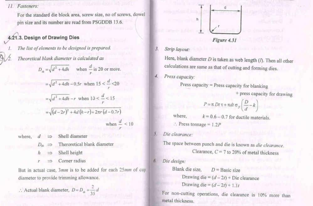
100 100
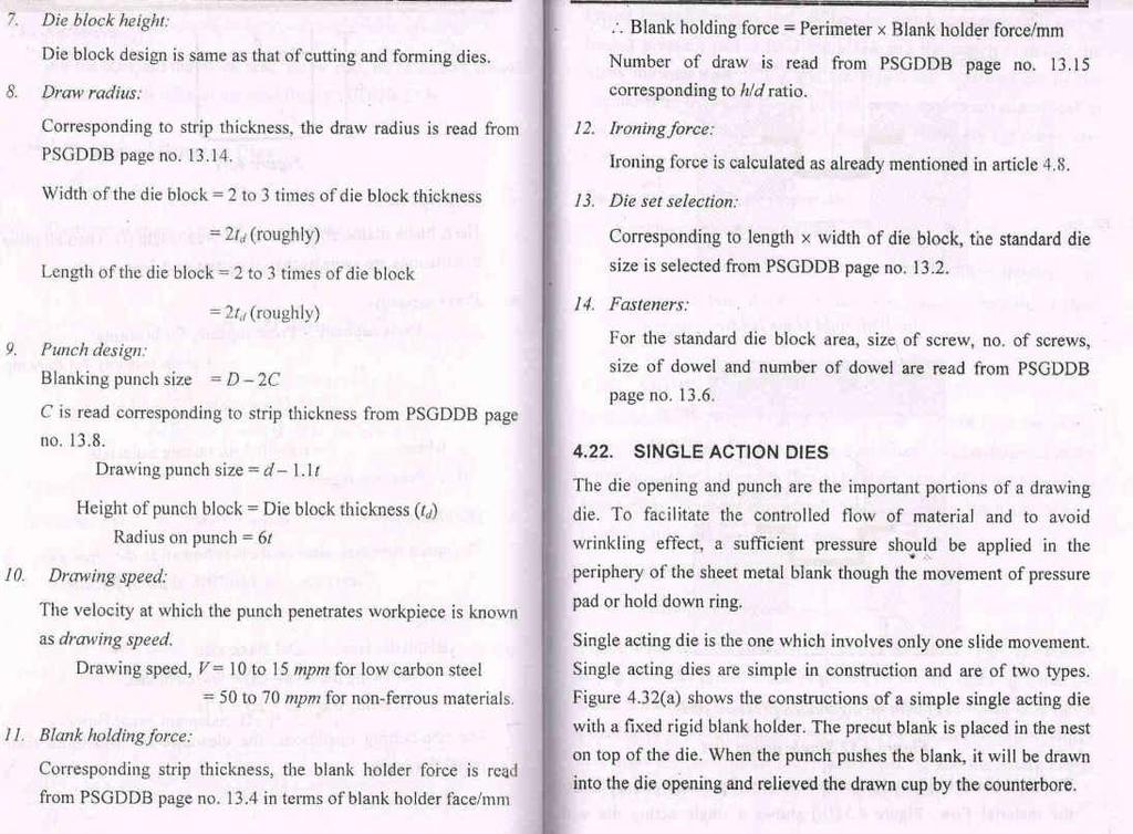
101 101
102 UNIT V OTHER FORMING TECHNIQUES Bulging, Swaging, Embossing, coining, curling, hole flanging, shaving and sizing, assembly, fine Blanking dies recent trends in tool design- computer Aids for sheet metal forming Analysis basic introduction - tooling for numerically controlled machinessetup reduction for work holding Single minute exchange of dies Poka Yoke - Course should be supplemented with visits to industries. PART A 1. What do you understand by the terms: Single and Double action dies? (ODD 2015) Single action die is the one which involves only one slide movement. It is simple in construction. In double action dies, two individual rams control both the punch movement and blank holder movement. 2. Highlight the role of computers in sheet metal forming analysis. (ODD 2015) 1. To compute the blank size for bent, formed and/or drawn work piece. 2. To optimize the sheet strip layout 3. To select the appropriate press tool to be used. 4. To decide the position of punch and shank centers 5. To compute the shear force and sizes of die, stripper, screws and dowels. 6. To draft the assembly drawing, bill of materials and detailed drawing. 7. To analyze the forming behavior of sheet metal. 102
 Hole flanging (ii)")
103 . PART B 1. Write short notes on following; (i) Hole flanging (ii) Curling (iii) sizing (iv) Poka Yoke (EVEN 15) 103
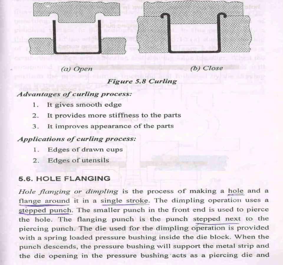
104 104
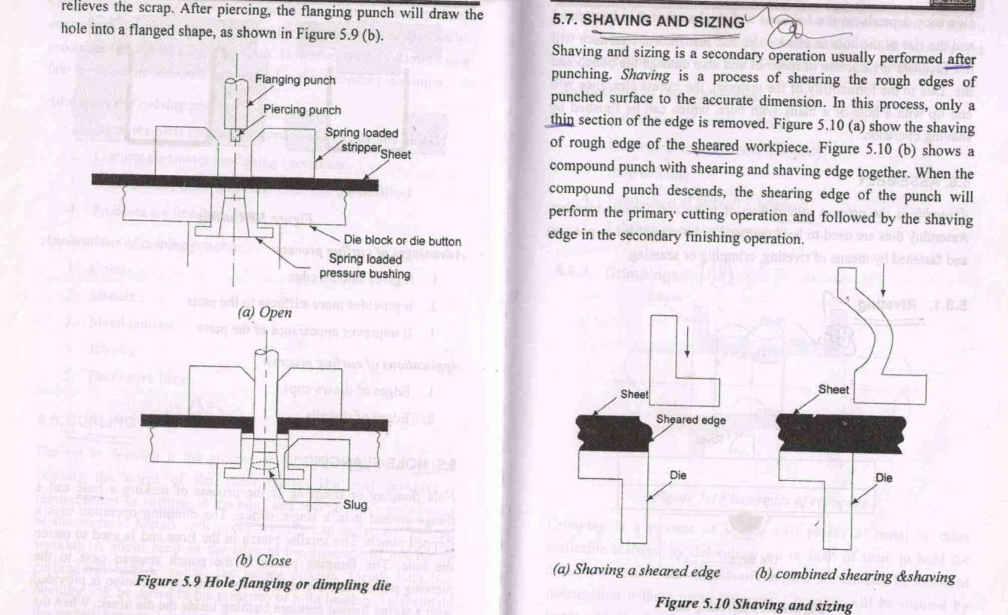
105 105

106 2. Discuss about various tooling in NC Machines. (ODD 15) 106
 Swaging (iii) Embossing (iv) Coining (ODD 15)")
107 3. Write short notes on following; (i) Bulging (ii) Swaging (iii) Embossing (iv) Coining (ODD 15) 107
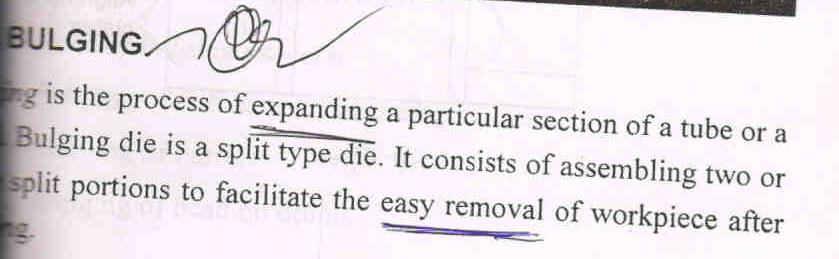

108 108
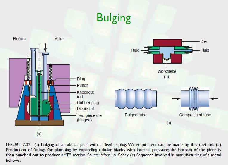
109 109

110 Embossing Embossing is the operation used in making raised figures on sheets with its corresponding relief on the other side. The process essentially involves drawing and bending of the metal. An example of the embossing operation is shown. 110
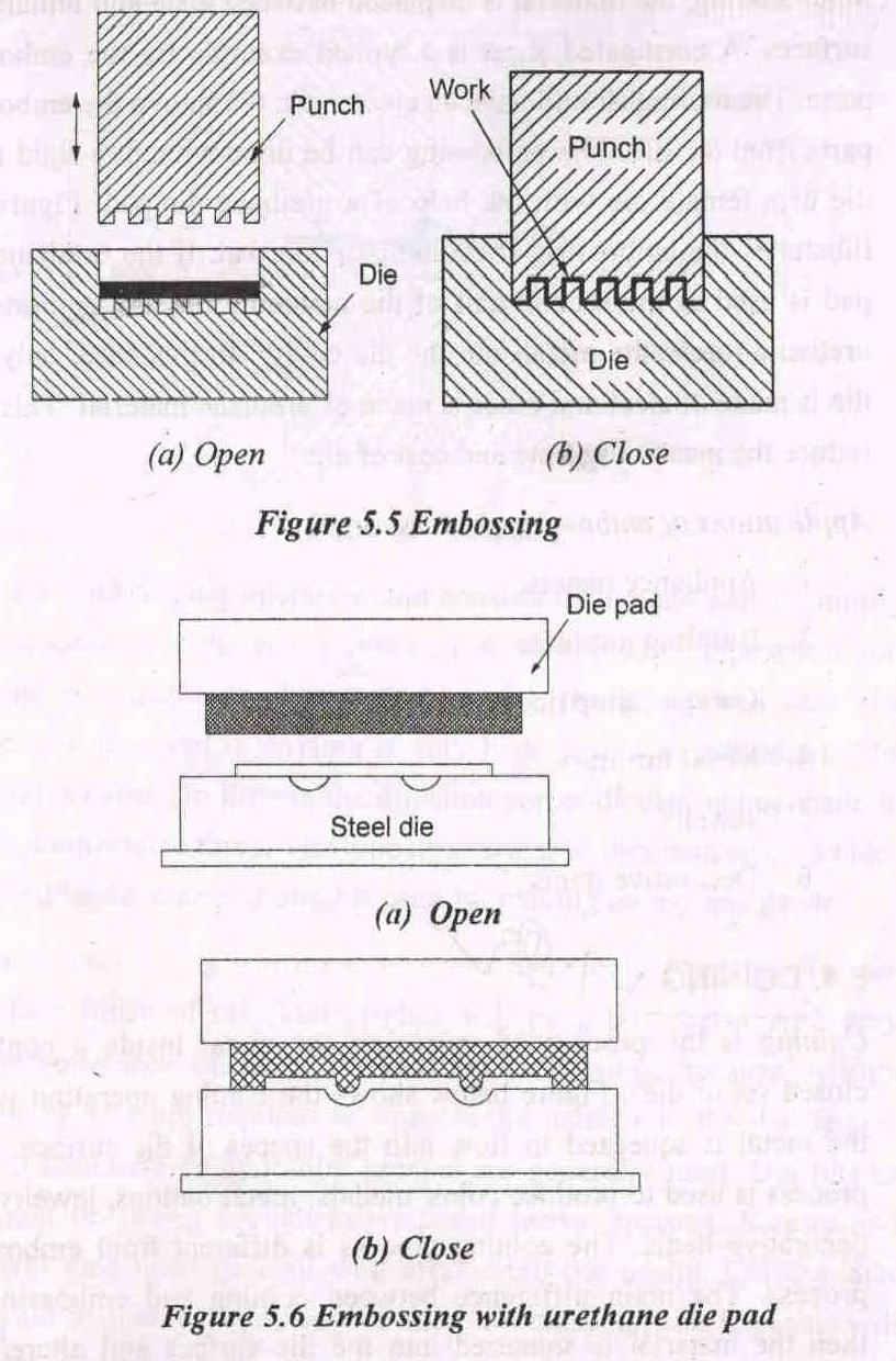
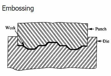
111 111

112 The die set consists essentially of a die and punch with the desired contours, so that when the punch and die meet the clearance between them is same as that of the sheet thickness. Embossing operation is generally used for providing dimples on sheets to increase their rigidity and for decorative sheet work used for panels in houses and religious places. Coining Coining is essentially a cold forging operation except for the fact that the flow of the metal occurs only at the top layers and not the entire volume. The coining die consists of the punch and die which are engraved with the necessary details required on both sides of the final object. The pressures involved in coining are very high, of the order of 1600 MPa because of the very fine details that are normally desired in coining. The type of impression obtained on both sides would be different unlike the embossing. Coining is used for making coins, medals and similar articles, and for impressions on decorative items. 112
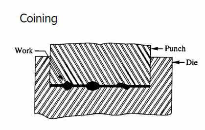
113 113
Design of Jigs, Fixtures, Press Tools and Moulds UNIT - 1 LOCATING AND CLAMPING PRINCIPLES
 Design of Jigs, Fixtures, Press Tools and Moulds UNIT - 1 LOCATING AND CLAMPING PRINCIPLES 1. Define the term Tool design. Tool design is the process of designing and developing the tools, methods, and
The jigs and fixtures are the economical ways to produce a component in mass production system. These are special work holding and tool guiding device
 The jigs and fixtures are the economical ways to produce a component in mass production system. These are special work holding and tool guiding device Quality of the performance of a process largely influenced
Locating Principles & Devices
 Locating Principles & Devices 1 LOCATING PRINCIPLES To position the work piece w.r.t. to tool, to ensure precision in machining Locating: dimensional and positional relationship b/w work piece and tool
ANNAI MATHAMMAL SHEELA ENGINEERING COLLEGE, NAMAKKAL DEPARTMENT OF MECHANICAL ENGINEERING DESIGN OF JIGS, FIXTURES AND PRESS TOOLS
 ANNAI MATHAMMAL SHEELA ENGINEERING COLLEGE, NAMAKKAL DEPARTMENT OF MECHANICAL ENGINEERING DESIGN OF JIGS, FIXTURES AND PRESS TOOLS UNIT - 1 LOCATING AND CLAMPING PRINCIPLES PART- A 1. Define the term Tool
ME 2029 DESIGN OF JIGS AND FIXTURES NOTES UNIT I LOCATING AND CLAMPING PRINCIPLES
 ME 2029 DESIGN OF JIGS AND FIXTURES NOTES UNIT I LOCATING AND CLAMPING PRINCIPLES Locating and clamping are the critical functions of any work holder. As such, the fundamental principles of locating and
Jigs and fixtures are devices used to facilitate production work, making interchangeable pieces of work possible at a savings in cost of production.
 INTRODUCTION Over the past century, manufacturing has made considerable progress. New machine tools, high-performance cutting tools, and modern manufacturing processes enable today's industries to make
MFG 316 Chapter 4 //Workholding Principles
 Workholding Principles All devices that grip, hold, chuck, or retain a workpiece in order to perform a manufacturing operation. Force=hydraulic, pneumatic, electrical, mechanical Force multiplication by
Trade of Toolmaking. Module 5: Press Tools, Jigs & Fixtures, Mouldmaking Unit 5: Jigs and Fixtures Phase 2. Published by
 Trade of Toolmaking Module 5: Press Tools, Jigs & Fixtures, Mouldmaking Unit 5: Jigs and Fixtures Phase 2 Published by SOLAS 2014 Unit 5 1 Table of Contents Document Release History... 3 Unit Objective...
Jig and Fixture Design. Chapter 1: Types and Functions of Jigs and Fixtures
 Jig and Fixture Design Chapter 1: Types and Functions of Jigs and Fixtures Purpose of Tool Design Objectives: Provide simple, easy-to-operate tools for maximum efficiency Reduce manufacturing expenses
Work Holding Principles ITCD Rajeev Madhavan Nair
 Work Holding Principles ITCD 301-001 Work Holding One of the most important elements of the machining process Work holder includes all devices that hold, grip or chuck a work piece to perform a manufacturing
Other Types Of Bushes
 Other Types Of Bushes Circuit board drill bushes: Designed to accommodate larger shank for making drill on circuit board Chip breaker bushes: Designed with chip breaking notch. Reduces friction and heat
WHAT? WHERE? HOW?
 JIGS WHAT? WHERE? HOW? Introduction Mass production aims at high productivities to reduce unit cost and inter-changeabilites to facilitate easy assembly. Jigs are useful in mass production. They provide
DESIGN AND MANUFACTURING OF MODIFIED ANGLE JIG TOOL
 DESIGN AND MANUFACTURING OF MODIFIED ANGLE JIG TOOL ABHIJIT TAGADE 1, NILESH NIRWAN 2, MANISH MISHRA 3 1. M.Tech student, Wainganga college of engineering, Nagpur (India) 2. Facutly, Wainganga college
STEEL RULE. Stock TRY SQUARE
 FITTING INTRODUCTION Fitting consists of a handwork involved in fitting together components usually performed at a bench equipped with a vice and hand tools. The matting components have a close relation
5-axis clamping system compact
 5-axis clamping system compact 395 5-axis clamping system compact Function We are setting standards with the new KIPP 5-axis clamping system compact in this field. The system was specifically designed
LANDMARK UNIVERSITY, OMU-ARAN
 LANDMARK UNIVERSITY, OMU-ARAN LECTURE NOTE: DRILLING. COLLEGE: COLLEGE OF SCIENCE AND ENGINEERING DEPARTMENT: MECHANICAL ENGINEERING PROGRAMME: MECHANICAL ENGINEERING ENGR. ALIYU, S.J Course code: MCE
Government of Karnataka Department of Technical Education Board of Technical Examinations, Bangalore
 Government of Karnataka Department of Technical Education Board of Technical Examinations, Bangalore CIE- 25 Marks Course Title: JIGS AND FIXTURES Scheme (L:T:P) : 4:0:0 Total Contact Hours: 52 Type of
Lathe is a machine, which removes the metal from a piece of work to the required shape & size HENRY MAUDSLAY
 TURNING MACHINES LATHE Introduction Lathe is a machine, which removes the metal from a piece of work to the required shape & size HENRY MAUDSLAY - 1797 Types of Lathe Engine Lathe The most common form
Design and Fabrication of Angular Drilling Jig
 Design and Fabrication of Angular Drilling Jig Karthikeyan P 1, Arulmani J 2, Sirajudeen A 3, Philip Perinba Vinith R 4, Yokesh M 5, Arun P 6 1,2 Asst.Professor, M.Tech/Department of Mechanical Engineering,
STEVENS SUBPLATES. STEVENS ENGINEERING, INC. TOLL-FREE WEB FAX
 STEVENS SUBPLATES Spacing of hole patterns on Stevens accessories is identical to the pattern on Stevens Subplates. Insertion of the pull dowels thru bushed holes in the accessory into corresponding bushed
ROOP LAL Unit-6 Lathe (Turning) Mechanical Engineering Department
 Mechanical Engineering Department") Notes: Lathe (Turning) Basic Mechanical Engineering (Part B) 1 Introduction: In previous Lecture 2, we have seen that with the help of forging and casting processes, we can manufacture machine parts of
Notes: Lathe (Turning) Basic Mechanical Engineering (Part B) 1 Introduction: In previous Lecture 2, we have seen that with the help of forging and casting processes, we can manufacture machine parts of
Lathes. CADD SPHERE Place for innovation Introduction
 Lathes Introduction Lathe is one of the most versatile and widely used machine tools all over the world. It is commonly known as the mother of all other machine tool. The main function of a lathe is to
International Journal of Science and Engineering Research (IJ0SER), Vol 3 Issue 3 March , (P) X
, Vol 3 Issue 3 March , (P) X") Design And Optimization Techniques Using In Turning Fixture M Rajmohan 1, K S Sakthivel 1, S Sanjay 1, A Santhosh 1, P Satheesh 2 1 ( UG Student ) 2 (Assistant professor)mechanical Department, Jay Shriram
Design And Optimization Techniques Using In Turning Fixture M Rajmohan 1, K S Sakthivel 1, S Sanjay 1, A Santhosh 1, P Satheesh 2 1 ( UG Student ) 2 (Assistant professor)mechanical Department, Jay Shriram
4. PRESS AND PRESS WORK
 4. PRESS AND PRESS WORK Q. Which are the materials used for press work? GALVANISED IRON Zinc-coated iron is known as "galvanised iron"'. This soft steel sheet is popularly known as Gl sheet. Applications:
Clamping devices 521
 Clamping devices 521 522 Product overview Clamping devices Adjustable straps K0001 Hook clamps K0012 Goose-neck straps with long slot K0002 Page 526 Hook Clamps with collar K0013 Page 535 Equipped clamps
Lathe. A Lathe. Photo by Curt Newton
 Lathe Photo by Curt Newton A Lathe Labeled Photograph Description Choosing a Cutting Tool Installing a Cutting Tool Positioning the Tool Feed, Speed, and Depth of Cut Turning Facing Parting Drilling Boring
TURNING BORING TURNING:
 TURNING BORING TURNING: FACING: Machining external cylindrical and conical surfaces. Work spins and the single cutting tool does the cutting. Done in Lathe. Single point tool, longitudinal feed. Single
Design and Analysis of Press Tool Assembly
 Design and Analysis of Press Tool Assembly Raveendra M.Tech Student ABSTRACT Press working may be defined as a chip less manufacturing process by which various components are made from sheet metal. This
Design of Fixture for Cross Hole Drilling of Flange-Yoke
 OPEN ACCESS International Journal Of Modern Engineering Research (IJMER) Design of Fixture for Cross Hole Drilling of Flange-Yoke Tushar D. Patil 1, Aditya V. Kavdikar 2, Anish T. Nadar 3, Gitesh M. Shirsat
Student, Department of Mechanical Engineering, Knowledge Institute of Technology, Salem, Tamilnadu (1,3)
") International Journal of Scientific & Engineering Research, Volume 7, Issue 5, May-2016 11 Combined Drilling and Tapping Machine by using Cone Mechanism N.VENKATESH 1, G.THULASIMANI 2, S.NAVEENKUMAR 3,
International Journal of Scientific & Engineering Research, Volume 7, Issue 5, May-2016 11 Combined Drilling and Tapping Machine by using Cone Mechanism N.VENKATESH 1, G.THULASIMANI 2, S.NAVEENKUMAR 3,
Lathe Accessories. Work-holding, -supporting, and driving devices
 46-1 Lathe Accessories Divided into two categories Work-holding, -supporting, and driving devices Lathe centers, chucks, faceplates Mandrels, steady and follower rests Lathe dogs, drive plates Cutting-tool-holding
1. The Lathe. 1.1 Introduction. 1.2 Main parts of a lathe
 1. The Lathe 1.1 Introduction Lathe is considered as one of the oldest machine tools and is widely used in industries. It is called as mother of machine tools. It is said that the first screw cutting lathe
Turning and Lathe Basics
 Training Objectives After watching the video and reviewing this printed material, the viewer will gain knowledge and understanding of lathe principles and be able to identify the basic tools and techniques
Copyright 2009 Society of Manufacturing Engineers. FUNDAMENTALS OF TOOL DESIGN Fixture Design - DF
 FUNDAMENTALS OF TOOL DESIGN Fixture Design - DF SCENE 1. DF26A, FTD87, 03:20:15:00-03:20:46:00 zoom out, milling operation DF26B, CGS: Milling Fixtures Lathe Fixtures Grinding Fixtures Broaching Fixtures
PLANING MACHINE. Crossrail. Tool head. Table. Table. reciprocating movement Roller. Bed. Open Side Planer Sketch S-8.1-A. Feed screws.
 8 PLANING MACHINE A8.1 : Planing Machine Tool head Table reciprocating movement Roller Table Cross-rail Bed Column Open Side Planer Sketch S-8.1-A Introduction This is also a reciprocating type of machine
Design for machining
 Multiple choice questions Design for machining 1) Which one of the following process is not a machining process? A) Planing B) Boring C) Turning D) Forging 2) The angle made between the rake face of a
Motorized M3 AX7200 Rotary-Style Gasket Cutter Operating Instructions
 Motorized M3 AX7200 Rotary-Style Gasket Cutter Operating Instructions INTRODUCTION Congratulations! You are the owner of the finest rotary-style gasket cutter in the world. Originally developed and patented
Typical Parts Made with These Processes
 Turning Typical Parts Made with These Processes Machine Components Engine Blocks and Heads Parts with Complex Shapes Parts with Close Tolerances Externally and Internally Threaded Parts Products and Parts
Trade of Toolmaking. Module 5: Press Tools, Jigs & Fixtures, Mouldmaking Unit 2: Blanking Tool (Unguided) Phase 2. Published by
 Phase 2. Published by") Trade of Toolmaking Module 5: Press Tools, Jigs & Fixtures, Mouldmaking Unit 2: Blanking Tool (Unguided) Phase 2 Published by SOLAS 2014 Unit 2 1 Table of Contents Document Release History... 3 Unit Objective...
Trade of Toolmaking Module 5: Press Tools, Jigs & Fixtures, Mouldmaking Unit 2: Blanking Tool (Unguided) Phase 2 Published by SOLAS 2014 Unit 2 1 Table of Contents Document Release History... 3 Unit Objective...
MACHINE TOOL ACCESSORIES
 VERTICAL 5-C COLLET VISE SERIES 344: VERTICAL 3-C COLLET VISE SERIES 344: : 2-1/2 x 7-3/4 Height: 4 Small movement of lever opens or closes collet. 2030000 CAM OPERATED 5-C HORIZONTAL/VERTICAL COLLET FIXTURE
Build a Drill Press Vise
 Youth Explore Trades Skills Introduction This activity plan will develop the student s machining and metalworking skills as they fabricate a multi-piece steel vise. The project will encompass basic lathe
Turning and Related Operations
 Turning and Related Operations Turning is widely used for machining external cylindrical and conical surfaces. The workpiece rotates and a longitudinally fed single point cutting tool does the cutting.
Cross Peen Hammer. Introduction. Lesson Objectives. Assumptions
 Introduction In this activity plan students will develop various machining and metalworking skills by building a two-piece steel hammer. This project will introduce basic operations for initial familiarization
Quick-Release Front Vise 05G34.01
 Quick-Release Front Vise 05G34.01 Patent Pending Introduction A front vise is the most generally useful vise on a typical workbench. It can be used for clamping parts on edge within the jaws, for clamping
The new generation with system accessories. Made in Europe!
 1 The new generation with system accessories. Made in Europe! Of cast iron, wide-legged prismatic guide. For vibration-free work even at high loads. Rear flange for mounting the mill/drill head PF 230.
FixLogix CMM Fixture System Instructions
 FixLogix CMM Fixture System Instructions FixLogix uses t-slot technology to provide simple fixture construction. Components are locked onto the plate or linear frames using FixLogix t-nuts. This design
CARIBBEAN EXAMINATIONS SECONDARY EDUCATION CERTIFICATE EXAMINATION MECHANICAL ENGINEERING TECHNOLOGY. Paper 02 - Technical Proficiency.
 FORM TP 2011094 CARIBBEAN EXAMINATIONS SECONDARY EDUCATION CERTIFICATE EXAMINATION TEST CODE 01335020 COUNCIL MECHANICAL ENGINEERING TECHNOLOGY Paper 02 - Technical Proficiency 2'h hours MAY/JUNE 2011
Machining. Module 6: Lathe Setup and Operations. (Part 2) Curriculum Development Unit PREPARED BY. August 2013
 Curriculum Development Unit PREPARED BY. August 2013") Machining Module 6: Lathe Setup and Operations (Part 2) PREPARED BY Curriculum Development Unit August 2013 Applied Technology High Schools, 2013 Module 6: Lathe Setup and Operations (Part 2) Module Objectives
Machining Module 6: Lathe Setup and Operations (Part 2) PREPARED BY Curriculum Development Unit August 2013 Applied Technology High Schools, 2013 Module 6: Lathe Setup and Operations (Part 2) Module Objectives
The economical and versatile answer to Primary & Secondary Precision Machining and Assembly.
 Vertomat Rotary Transfer Machines The economical and versatile answer to Primary & Secondary Precision Machining and Assembly. For Machine Sales, Spare Parts Sales, Component Feasibility/Machine Capability,
Screws. Introduction. 1. Nuts, bolts and screws used to clamp things together. Screws are used for two purposes:
 Screws Introduction Screws are used for two purposes: 1. To clamp things together. 2. To control motion. 1. Nuts, bolts and screws used to clamp things together. Nuts, bolts and screws that are used for
Agricultural Mechanics and Technology Power Tool Safety Rules
 Agricultural Mechanics and Technology Power Tool Safety Rules Name: BAND SAW Use: Cutting curves, circles and irregular shapes. 1. Use clean SHARP blades. 2. The teeth should always point DOWN. 3. Adjust
Ahsanullah University of Science and Technology (AUST) Department of Mechanical and Production Engineering
 Department of Mechanical and Production Engineering") Ahsanullah University of Science and Technology (AUST) Department of Mechanical and Production Engineering LABORATORY MANUAL For the students of Department of Mechanical and Production Engineering 1 st
Ahsanullah University of Science and Technology (AUST) Department of Mechanical and Production Engineering LABORATORY MANUAL For the students of Department of Mechanical and Production Engineering 1 st
Features of TOOLFAST Clamping Devices and Clamping Elements
 PART I CLAMPING DEVICES & CLAMPING ELEMENTS INTRODUCTION In the following pages of this part of catalogue, different types & sizes of clamping devices and clamping elements manufactured by us are illustrated.
Design a drill jig for drilling 4 holes in the following component.
 Design a drill jig for drilling 4 holes in the following component. Design procedure for Jig a. Selection of Jig A leaf (or) latch jig is selected to accomplish this component. The leaf is hinged on one
Introduction to Machining: Lathe Operation
 Introduction to Machining: Lathe Operation Lathe Operation Lathe The purpose of a lathe is to rotate a part against a tool whose position it controls. It is useful for fabricating parts and/or features
1. Enumerate the most commonly used engineering materials and state some important properties and their engineering applications.
 Code No: R05310305 Set No. 1 III B.Tech I Semester Regular Examinations, November 2008 DESIGN OF MACHINE MEMBERS-I ( Common to Mechanical Engineering and Production Engineering) Time: 3 hours Max Marks:
CNC EXPANDING MANDRELS
 CNC EXPANDING MANDRELS ID CLAMPING OFFERS FULL OD PART ACCESS PARALLEL EXPANSION FOR OPTIMUM ACCURACY AND GRIP FORCE LARGE RANGE IN STOCK FOR IMMEDIATE SHIPMENT ROYAL CNC EXPANDING MANDRELS Rigid and Accurate
Tools for Plumbing. Introduction
 2 Tools for Plumbing Introduction So far, we have studied the importance of plumbing system, its stages and the role and responsibilities of a plumber. We will now look at the various tools that help a
The new generation with system accessories. Made in Germany!
 1 The new generation with system accessories. Made in Germany! For face, longitudinal and taper turning, thread-cutting. For machining steel, brass, aluminium and plastic. Mounting flange for fastening
Permanent fasteners: Riveted joints Welded joints Detachable joints: Threaded fasteners screws, bolts and nuts, studs. Cotter joints Knuckle joints
 Instructional Objectives At the end of this lesson, the students should have the knowledge of Fasteners and their types: permanent and detachable fasteners. Different types of pin joints. Different types
1/2/2016. Lecture Slides. Screws, Fasteners, and the Design of Nonpermanent Joints. Reasons for Non-permanent Fasteners
 Lecture Slides Screws, Fasteners, and the Design of Nonpermanent Joints Reasons for Non-permanent Fasteners Field assembly Disassembly Maintenance Adjustment 1 Introduction There are two distinct uses
Procedure for Longworth Chuck construction
 Procedure for Longworth Chuck construction Overall construction The Longworth chuck is composed of three major components. Connected to the lathe spindle is some device that fastens to the first of two
ACCESSORIES.
 Rotary, Dividing, & Cross Tables 166 Indexes 167 Dividing Heads 168 Screw Jack Sets 168 Angle Plates & V-Blocks 169 Quick Change Tool Posts & 170-171 CNC Tool Holder Bushings 171 Lathe Chucks 172-177 www.sowatool.com
FITTING INTRODUCTION:
 FITTING INTRODUCTION: Machine tools are capable of producing work at a faster rate, but there are occasions when components are processed at the bench. Sometimes it becomes necessary to replace or repair
Chapter 22 MACHINING OPERATIONS AND MACHINE TOOLS
 Chapter 22 MACHINING OPERATIONS AND MACHINE TOOLS Turning and Related Operations Drilling and Related Operations Milling Machining Centers and Turning Centers Other Machining Operations High Speed Machining
PREVIEW COPY. Table of Contents. Lathe Setup and Workpiece Preparation...3. Lesson Two Rough Turning and Finish Turning...19
 Table of Contents Lesson One Lathe Setup and Workpiece Preparation...3 Lesson Two Rough Turning and Finish Turning...19 Lesson Three Lesson Four Boring and Counterboring...35 Cutting Internal Threads and
MECHANICAL ASSEMBLY John Wiley & Sons, Inc. M. P. Groover, Fundamentals of Modern Manufacturing 2/e
 MECHANICAL ASSEMBLY Threaded Fasteners Rivets and Eyelets Assembly Methods Based on Interference Fits Other Mechanical Fastening Methods Molding Inserts and Integral Fasteners Design for Assembly Mechanical
Precision made in Germany. As per DIN The heart of a system, versatile and expandable.
 1 Precision made in Germany. As per DIN 8606. The heart of a system, versatile and expandable. Main switch with auto-start protection and emergency off. Precision lathe chuck as per DIN 6386 (Ø 100mm).
IJRASET: All Rights are Reserved. UG Scholars, Department of Mechanical Engineering, SNS College of engineering, Coimbatore
 Fixture for bundle cutting of tubes and rods in saw cutting machine Mr.R.Pradeep Kumar 1, U.Rupesh Kiran 2, R. Sanjhay 3, G.Subramanian 4, R.Vijayakumar 5 1 Assistant Professor, Department of Mechanical
B.E Mini Projects
 B.E Mini Projects 2017-2018 S.NO CMP001 CMP002 CMP003 CMP004 CMP005 CMP006 CMP007 CMP008 CMP009 CMP010 CMP011 CMP012 CMP013 CMP014 CMP015 CMP016 CMP017 CMP018 CMP019 CMP020 CMP021 CMP022 CMP023 CMP024
Review on Design of Jig and Fixture for Turning on Lathe
 Review on Design of Jig and Fixture for Turning on Lathe Gulam Shaikh 1, Siddiki Arshadali 2, Shaikh Masood 3, Thakur Aditya 4, Juberbhai Mansuri 5 1 Theem College of engineering, shaikhgulam45@gmail.com
SYLLABUS. Apprenticeship Training Scheme
 SYLLABUS For the trade of JIGS AND FIXTURE MAKER UNDER Apprenticeship Training Scheme Government of India Ministry of Labour & Employment Directorate General of Employment & Training New Delhi-110001 GENERAL
Pull-down clamps. No Low height clamping jaws, model Bulle
 Pull-down clamps The wedge action of clamping jaws is the characteristic feature of these pull down clamps. It causes the pull down effect, which presses the workpiece against both, stop and machine table.
High Precision Air Chucks
 Precision Workholding Solutions High Precision Air Chucks www..com Improve productivity and lower the cost of secondary machining operations..... through high concentricity. Holding close concentricity
Trade of Toolmaking Module 2: Turning Unit 1: Machine Controls and Operations Phase 2
 Trade of Toolmaking Module 2: Turning Unit 1: Machine Controls and Operations Phase 2 Published by SOLAS 2014 Unit 1 1 Table of Contents Document Release History... 3 Unit Objective... 4 Introduction...
Precision Grinding and Control Vise. Vises PSS. Tools and Accessories. For more Information current prices, please
 PSK 50 shown incl. pull-down feature Vises Precision Grinding and Control Vise high precision, robust structure, hardened and ground v-grooves, high holding capacity can be used on 4 different sides face
Precision Manufacturing
 Precision Manufacturing 216 North Main Street. Freeport, NY 11520 Phone: 888-260-7466 / Fax: 516-771-6444 sales@ondrivesus.com www.ondrivesus.com Know Linear Your Shaft Shoulder Supports Screws By Dennis
Special reamers. Figure N 1 Reamer with descending cutting edges in carbide (Cerin)
") Special reamers There is a wide category of special reamers, ie non-standard, that are suitable to address particular problems encountered in the finishing holes, both for maintenance of individual pieces
Special reamers There is a wide category of special reamers, ie non-standard, that are suitable to address particular problems encountered in the finishing holes, both for maintenance of individual pieces
Clamping bolts Eccentrical cams clamping units
 2.3 Shaft Clamping bolts Eccentrical cams clamping units 2.9 2.8 2.7 2.6 2.5 2.4 2.3 2.2 2.1 2.3 Clamping bolts, Eccentrical cams, Shaft clamping units Page 641 2.3 Clamping bolts, Eccentrical cams, Shaft
PRESS & PRESS WORK
 Topic and Contents Hours Marks 2.1 Introduction 08 Marks Materials used in press work for automobile applications. Classifications of presses and terminology used in presses Major parts of Fly press 2.2
MATERIAL COMBINATION NUMBER 2: Corrosive environment requiring harder, wear-resistant seating faces and resistance to dezincification.
 Cast Iron Slide Gates Spec Sheet General The contractor shall furnish and install the following cast iron slide gate assemblies as listed on the Gate Schedule and detailed on the manufacturer s drawings.
Unit IV Drawing of rods, wires and tubes
 Introduction Unit IV Drawing of rods, wires and tubes Drawing is a process in which the material is pulled through a die by means of a tensile force. Usually the constant cross section is circular (bar,
FACULTY OF ENGINEERING DESIGN AND PRODUCTION ENGINEERING DEPARTMENT. Credit Hour System Metrology Lab 1 MDP 240 (1) Fixed gauges. Metrology laboratory
 Fixed gauges. Metrology laboratory") FACULTY OF ENGINEERING DESIGN AND PRODUCTION ENGINEERING DEPARTMENT Report On: Credit Hour System Metrology Lab 1 MDP 240 (1) Fixed gauges Metrology laboratory Class No: B.N. Student Name Remark Signature
FACULTY OF ENGINEERING DESIGN AND PRODUCTION ENGINEERING DEPARTMENT Report On: Credit Hour System Metrology Lab 1 MDP 240 (1) Fixed gauges Metrology laboratory Class No: B.N. Student Name Remark Signature
Holemaking Products & Accessories
 Holemaking Products & Made of top-of-the-line materials for longer lasting performance, Klein's diverse line of drill bits and holemaking products and accessories provide accuracy and consistency to get
SALE SALE SALE palmgren.com chhanson.com SWIVEL BASES SPEED HANDLES
 FRIENDS OF PALMGREN SPECIAL OFFERS WORKHOLDING S EVENT DUAL FORCE PRECISION MACHINE VISES Palmgren s Dual Force line of machine vises are all designed for precision part clamping and are ideal for use
Universal Machining Chucks. 4-Jaw Vertical
 Universal Machining Chucks 4-Jaw Vertical Parts are gripped firmly by the formed jaws, ensuring high precision (deviation within 0.03mm) Large workpieces can be held tight with the low profile vise body
A SIX STATION TURRET HEAD
 A SIX STATION TURRET HEAD by Ken Metcalfe IN INTRODUCING this piece of workshop equipment, a little explanation of machine tool phraseology would not go amiss. The capstan rest for the tool head of a capstan
The new generation with system accessories. Made in Germany!
 1 The new generation with system accessories. Made in Germany! For face, longitudinal and taper turning, thread-cutting. For machining steel, brass, aluminium and plastic. Mounting flange for fastening
no mm no Dividers with scriber 150 mm NEW Square wedge-shaped knife edges on the length side
 Summer Promotion valid until 30.06.2013 all quoted prices are incl. VAT for deliveries to EU countries to customers with valid VAT-no. and for deliveries in non EU member countries the VAT is not applicable
UNIT 9 TOOLS FOR BASIC LAYOUT
 UNIT 9 TOOLS FOR BASIC LAYOUT Tools for Basic Structure 9.1 Introduction Objectives 9.2 Tools for Scribing 9.3 Accessories 9.4 Summary 9.5 Key Words 9.1 INTRODUCTION The process of making reference mark
7x --Tailstock Cam Lock
 7x --Tailstock Cam Lock By Magic Brian magicbrian40@yahoo.com Probably the most pleasing mod to have, but often not done through lack of milling facility s This version does NOT require a mill. MATERIALS
STRENGTH Aligned teeth provide superior gripping power over standard vertical teeth. STRENGTH Diamond serrated jaws provide a firm grip
 STRENGTH Aligned teeth provide superior gripping power over standard vertical teeth STRENGTH Diamond serrated jaws provide a firm grip PLIERS AND SNIPS Locking Pliers Slip Joint Pliers Electrician s Pliers
Cutting Tools and Cutting materials
 Cutting Tools and Cutting materials Cutting Tools One of most important components in machining process Performance will determine efficiency of operation Two basic types (excluding abrasives) Single point
Precision Milling Machine Vises. (Inch) (Inch) (Inch) Toolmaker s Vises. Jaw Depth
 (Inch) (Inch) Toolmaker s Vises. Jaw Depth") Precision Milling Machine Vises Vises & Accessories A B C D E F G H I J K L M N 17.01 4.63 9.25 6 2.05 18.74 3.87 2.87 1.50 1.75 4.84 0.69 7.5 0.71 79 277064 17.20 4.63 8.75 6 2.05 18.94 3.87 2.87 1.50
Precision Milling Machine Vises Vises & Accessories A B C D E F G H I J K L M N 17.01 4.63 9.25 6 2.05 18.74 3.87 2.87 1.50 1.75 4.84 0.69 7.5 0.71 79 277064 17.20 4.63 8.75 6 2.05 18.94 3.87 2.87 1.50
MECHANIC VISES VERSATILE, RUGGED AND BUILT WITH YOU IN MIND A B
 wiltontool.com Wilton is committed to being a supplier you can depend on for the epitome of quality, innovation and service. This isn t just a statement to make us sound good it s a reality that has been
Geometric Dimensioning and Tolerancing
 Geometric Dimensioning and Tolerancing (Known as GDT) What is GDT Helps ensure interchangeability of parts. Use is dictated by function and relationship of the part feature. It does not take the place
Chapter 22: Turning and Boring Processes. DeGarmo s Materials and Processes in Manufacturing
 Chapter 22: Turning and Boring Processes DeGarmo s Materials and Processes in Manufacturing 22.1 Introduction Turning is the process of machining external cylindrical and conical surfaces. Boring is a
WORKHOLDING MADE IN EUROPE MANUAL LATHE CHUCKS, CENTERS, ROTATING BODIES OIL COUNTRY CHUCKS, POWER CHUCKS, VTL CHUCKS, ROTARY TABLE PACKAGES
 EUROPEAN PRECISION & QUALITY WORKHOLDING MADE IN EUROPE MANUAL LATHE CHUCKS, CENTERS, ROTATING BODIES OIL COUNTRY CHUCKS, POWER CHUCKS, VTL CHUCKS, ROTARY TABLE PACKAGES EUROPEAN PRECISION & QUALITY With
MACHINE TOOLS LAB LABORATORY MANUAL
 Vanjari Seethaiah Memorial Engineering College Patancheru, Medak MACHINE TOOLS LAB LABORATORY MANUAL Department of Mechanical Engineering PREFACE Industrial Revolution has given man a lot many luxuries,
Tools: Sharpie, Square, Vise, Hack saw, Ruler, Punch, Hammer, File. 2. Cut the stock Place stock in vise and cut with hack saw
 Purpose: MAKE CATAPULT ARM Step 1 Tools: Sharpie, Square, Vise, Hack saw, Ruler, Punch, Hammer, File Materials: Flat aluminum ½ inch stock (see picture below) Gloves required 1. Pick up the aluminum ½