Assembly instructions
|
|
|
- Bartholomew Griffith
- 5 years ago
- Views:
Transcription


1 Assembly instructions
2 Important notes on VOSS assembly instructions In order to ensure maximum performance and functional reliability of VOSS products, the respective assembly instructions, operating conditions and tube recommendations have to be adhered to. We recommend that you use VOSS pre-assembly devices at all times. It is absolutely essential to follow the operating instructions for the respective pre-assembly device used. Do not start with assembly until you are absolutely sure that you have understood the operating and assembly instructions for each VOSS pre-assembly device or machine, tool and product. Incorrect handling leads to risks regarding safety and leak-tightness and can result in failure of the entire connection. It is impossible for the manufacturer to monitor whether the user is adhering to the operating and assembly instructions for individual pre-assembly devices or machines, tools and products, as well as what conditions prevail and what methods are used for installation, operation, application and maintenance of the individual products. Improper workmanship can lead to material damage, which in turn may pose a danger to life and limb. This means that VOSS Fluid GmbH can accept no responsibility or liability for loss, damage or costs incurred due to faulty installation, improper operation or incorrect application and maintenance or from any related issue. Failure to heed this warning will lead to loss of guarantee. VOSS Fluid GmbH reserves the right to make changes or additions to the information provided without prior notification. Customers can obtain the latest version of the operating and assembly instructions upon request, or from our download area at:
3 General notes on VOSS assembly instructions Make sure that all components, including the tubes, are clean before assembly is started and that they remain clean during the entire assembly process. Soiled components may lead to failure of the system. Before starting assembly, make sure that you have carried out all preparatory work in accordance with the respective instructions. Specifications concerning permissible steel tubes: seamless, cold-drawn and normalized precision steel tubes as specified in DIN EN , material E235+N, mat. no N or E355, mat. no The tubes must be ordered by specifying the outer diameter and the inner diameter. Specifications concerning permissible stainless steel tubes: seamless, cold-drawn and solution-annealed, scale-free stainless steel tubes in CFA or CFD delivery condition of dimensions and tolerances according to DIN EN and all other delivery conditions as specified in DIN EN , material X6CrNiMoTi , mat. no The tubes must be ordered by specifying the outer diameter and the inner diameter. The tubes should be prepared with the same thoroughness as preassembly and final assembly of the connection. Especially when using long tubes, check the end sections for damage or distortion. We recommend that pre-assembled tubes which are not to be finally assembled yet should be fitted with protective caps. Marking a stroke on the union nut and the tube makes it easier to achieve the correct number of turns when tightening the coupling. Before starting to assemble VOSS components with elastomer seals, always check that: the nut and the seal surfaces are clean and undamaged and/or the elastomer sealing is clean and undamaged Determining the tightening torque for screw couplings The tightening torques specified in the catalogue apply under the following conditions: steel fittings with VOSS coat surface coating the specified nominal pressure ranges assume that the mating material has a tensile strength of 600 N/mm² our recommendations on lubrication of the threaded studs are observed If other values for strength, modulus of elasticity and friction-surface combinations are used, the user has to adapt the tightening torque empirically. The recommended tightening torques have to be adhered to if the pressure range is to be fully utilized and the appropriate safety level is to be maintained. The recommended tightening torques for the threads are given in the tables for the respective type of thread. Explanation of symbols and other notes Visual inspection Turn until hand-tight or carry out another manual activity Use the tool to tighten the coupling according to the instructions Oil and lubricate at the point marked with an arrow All dimensions in millimetres [mm]


![[mm] L1 approx. [mm] L 6 7 0.8 7.8 55 L 8 7 1.1 8.1 55 L 10 7 0.5 7.5 60 L 12 7 0.5 7.5 62 L 15 7 0.5 7.5 62 L 187.5 1.](/docs-images/91/105423406/images/4-3.jpg "5 9 63 L 227.5 1.5 9 65 L 287.5 1.5 9 72 L 3510.5 2.8 13.3 75 L 42 11 3 14 75 S 8 7 2.4 9.4 55 S 107.5 2.4 9.9 60 S 127.")

4 Assembly instructions for BV-10 flared couplings 1 Notes Before starting the assembly work, read and observe the general notes in the up-to-date VOSS catalogue and check that your assembly instructions are up to date. These assembly instructions describe pre-assembly and final assembly of BV-10 flared couplings. Various VOSS pre-assembly devices are available for pre-assembly of the flared cone. The specifications in the respective operating instructions apply to the assembly procedures here. 2 Tube preparation 2.1 Determine the tubing dimensions using the following table of dimensions. L1 L2 Series Tube OD[mm] t5 [mm] x approx. [mm] L1 approx. [mm] L L L L L L L L L L S S S S S S S S S L2 approx. [mm] t5 x 2.2 Cut tubes at right angles. An angle tolerance of ±1 is permissible. Do not use tube cutters or angle grinders to cut tubes. Slightly deburr tube end inside and outside. Clean the tube. 0,2 max. ±1


5 BV-10 3 Flared cone pre-assembly 3.1 Push the BV-10 union nut and the clamping ring onto the tube as shown in the diagram. 3.2 Pre-assembly principle Only use a VOSS pre-assembly device for this process. During the pre-assembly the BV-10 flared cone is pressed into the tube. Set up the pre-assembly device and tools as described in the corresponding operating instructions. The outer diameter and wall thickness of the tube must be observed when choosing which tools to use. Pre-assemble the coupling as described in the operating instructions. 3.3 Apply a light film of lubricant (e.g. mineral-oil based hydraulic fluid HLP32) to toothed section and the cylindrical collar of the BV-10 flared cone and then push this onto the assembly mandrel.


6 BV Push the tube, with the BV-10 union nut and clamping ring on it, from the outside into the hole of the clamping jaws until it is centred on the BV-10 flared cone. The BV-10 union nut and clamping ring must remain outside of the assembly area. Make sure the correct clamping jaw pressure is set. The tube must not be able to slip when the assembly process is started. Follow the relevant sections of the operating instructions for the respective pre-assembly device. 3.5 Press the BV-10 flared cone into the tube. The optimum flared-cone assembly position is achieved when the remaining gap is 0.5 mm but not more than 1 mm. The BV-10 flared cone must not touch the flat surfaces of the tube end. Gap of 0.5 up to max. 1 mm required 3.6 Check that the flared cone fits squarely. 90 ± 1


7 BV-10 4 Final assembly 4.1 Push the O-ring on and check that it is bedded in the groove of the flared cone without being twisted. Lubricate the threads, the taper surface and the BV-10 union nut lightly (e.g. using mineral-oil based hydraulic fluid HLP32). 4.2 Insert the pre-assembled tube end into the cone of the coupling connecting piece at a straight angle. Make sure the O-ring is not damaged. Ensure a tensionfree connection of the pre-assembled tube and the coupling connecting piece. wrong correct 4.3 Turn the BV-10 union nut until it is hand-tight.
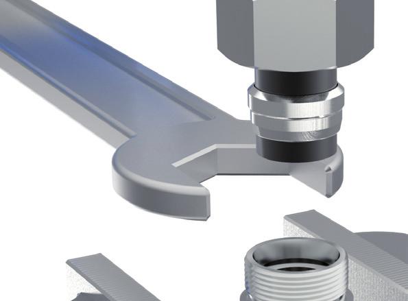
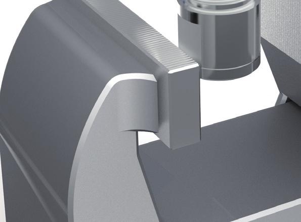
8 BV Tighten up the coupling by turning the BV-10 union nut by approx. 3/4 1 full turns. If the coupling is being installed on an already-installed tubing system, hold the coupling connecting piece with a spanner when tightening the coupling. approx. 3/4 1 turns 5 Re-assembly Each time the BV-10 flared cone is unscrewed, the O-ring must be checked for damage and replaced if necessary. For the second and all ensuing re-assembly processes, the BV-10 union nut must be tightened by only 1/4 1/2 turns after it has been hand-tightened. approx. 1/4 1/2 turns
Assembly instructions
 Assembly instructions Important notes on VOSS assembly instructions In order to ensure maximum performance and functional reliability of VOSS products, the respective assembly instructions, operating conditions
Assembly instructions
 Assembly instructions Important notes on VOSS assembly instructions In order to ensure maximum performance and functional reliability of VOSS products, the respective assembly instructions, operating conditions
PROFESSIONAL FLARING TOOL 001ERL 37 & ERL 37
 PROFESSIONAL FLARING TOOL 001ERL 37 & 45 002ERL 37 001ERL shown here OWNER S MANUAL 199R11215 EDUCATIONAL TIPS Make sure the end of the tube is cut off square. Before flaring, make sure the die clamp is
Operating Manual Riveting Tool R1. For installing blind rivet nuts
 L Operating Manual Riveting Tool R1 For installing blind rivet nuts Table of contents 1. Introduction 1.1 General instructions... 2 1.2 Description of the riveting tool... 3 1.3 Safety instructions...
Operator's manual. TruTool N 200 (1A1) english
 english") Operator's manual TruTool N 200 (1A1) english Table of contents 1. Safety...3 2. Description...5 2.1 Correct use...6 2.2 Technical data...7 3. Tool assembly...8 3.1 Changing the stroke rate...8 4. Operation...10
Operator's manual TruTool N 200 (1A1) english Table of contents 1. Safety...3 2. Description...5 2.1 Correct use...6 2.2 Technical data...7 3. Tool assembly...8 3.1 Changing the stroke rate...8 4. Operation...10
INSTRUCTION MANUAL Q-HYDRAULIC
 Dat: 15.04.02 No: 94-BA 5039E/1b TABLE OF CONTENTS Part III 3.0 Type code explanation 3.1 Service connections 3.2 Impeller clearance adjustment 3.2.1 Wear of wearing parts 3.2.2 General notes to adjustment
HMZ Locknuts simple and reliable locking devices
 simple and reliable locking devices Technical Product Information A Member of the Schaeffler Group Application Characteristics Application The new HMZ locknuts are easy to handle, permitting accurate and
ADDUCO Hydraulic Clamping Nut
 Translation of Original Operating Manual ADDUCO Hydraulic Clamping Nut Assembly and Operating Manual Superior Clamping and Gripping Imprint Imprint Copyright: This manual remains the copyrighted property
CLAMPEX KTR 401 Operating/Assembly instructions. 1 Technical data 2
 1 of 8 The CLAMPEX clamping set is a frictionally engaged, detachable shaft-to-shaft connection for cylindrical shafts and bores without feather key. Table of contents 1 Technical data 2 2 Advice 3 2.1
Hydraulic Adapters (080201/ MS# 51820) (080202/ MS# 51815) (071502) (081602) (080203/MS# 51813)
 (080202/ MS# 51815) (071502) (081602) (080203/MS# 51813)") Steel and stainless steel bite type fittings meet all design and performance requirements for hydraulic flareless tube fittings in Standard J514 published by the Society of Automotive Engineers (SAE).
Steel and stainless steel bite type fittings meet all design and performance requirements for hydraulic flareless tube fittings in Standard J514 published by the Society of Automotive Engineers (SAE).
MSR/MSB Mechanical Setting Tool
 Tech Unit No: 0620000004 Revision: B Approved By: Quality Engineer Date: 2014-12-16 MSR/MSB Mechanical Setting Tool FEATURES: Special designed Bow Spring provides positive control and allows one size Mechanical
HDL(M)6 Nut/Screw Assembly
6 Nut/Screw Assembly") HDL(M)6 Nut/Screw Assembly Remove, repair, and reassemble the nut and screw assembly in your HDL series double lock vise. In these instructions when we refer to the front of the vise or nut/screw assembly,
HDL(M)6 Nut/Screw Assembly Remove, repair, and reassemble the nut and screw assembly in your HDL series double lock vise. In these instructions when we refer to the front of the vise or nut/screw assembly,
HBS-AP ASSEMBLING INSTRUCTIONS
 ALUMINIUM PIPEWORK - ALUMINIUM PIPEWORK - ALUMINIUM PIPEWORK 97 HBS-AP ASSEMBLING INSTRUCTIONS 1. INTRODUCTION 1.1. This manual is very easy to consult and we recommend reading it before starting work,
Specification Tapped holes f. coupl Scope Allocation of the JED Numbers General...
 WABCO Specification 2003-07 Class: Engineering Guidelines Class No.:62 Tapped Holes for Couplings JED according to ISO 4039-2 464 Previous Edition Abbreviated Title 1985-11 Tapped holes f. coupl. 852 004
VERSAtoolTM SAE J533 & SAE J1453. Safety and Operating Manual
 VERSAtoolTM Mechanically Assisted / Manual Tube End Flare & Flange Machine SAE J533 & SAE J1453 Safety and Operating Manual I. Safety Instructions................................. Page 2 II. Specifications.....................................
IX. FLARED JOINTS IX. FLARED JOINTS
 IX. FLARED JOINTS IX. FLARED JOINTS While copper tube is usually joined by soldering or brazing, there are times when a mechanical joint may be required or preferred. Flared fittings (Figures 28 and 29)
Installation and Operational Instructions for ROBA -DX Couplings Type 931.3
 Please read these Operational Instructions carefully and follow them accordingly! Ignoring these Instructions may lead to malfunctions or to coupling failure, resulting in damage to other parts. Contents:
KBS 40 Locking Device is a frictionally engaged detachable shaft-hub connection for cylindrical shafts and bores without keyway.
 KBS 40 Locking Device is a frictionally engaged detachable shaft-hub connection for cylindrical shafts and bores without keyway. KBK Antriebstechnik GmbH Page 1 Features - delivered in mounted condition
Operating Manual. for CUTTING, PERFORATING, BENDING SLB120
 Operating Manual for CUTTING, PERFORATING, BENDING SLB120 31040\B06eng 0896 0 Contents 1. Scope of delivery... 1 2. Technical specifications... 1 3. Applications... 1 4. Commissioning... 2 5. Cutting...
RIVETING Rivet types Solid rivets Solid rivets are used less and less. They have been replaced in many cases by welding or bonding.
 10.1 Rivet types 10.1.1 Solid rivets Solid rivets are used less and less. They have been replaced in many cases by welding or bonding. Because of the large countersinking angle of 140 flat countersunk
REPUTE tube fittings are manufactured to stringent quality control program and internal standards which
 Introduction: REPUTE tube fittings are manufactured to stringent quality control program and internal standards which assure the highest quality available in the industry. Two ferrule tube fittings are
HC Hydraulic Expansion Chucks
 Technical Information HC Hydraulic Expansion Chucks design, function, effect, and application features, handling, and action application instructions precision tool length setting torques accessories sealed
REP Design LLC. 193 Winding Ridge Rd, Southington, CT INSTALLATION INSTRUCTIONS:
 REP Design LLC 193 Winding Ridge Rd, Southington, CT 06489 1-860.426.1894 n7emw@cox.net www.repdesign.us INSTALLATION INSTRUCTIONS: SHD-SO239 Super Heavy Duty SO-239Antenna Mounting System Thank you for
Maintenance Information
 16601023 Edition 2 January 2014 Air Impact Wrench 2705P1 Maintenance Information Save These Instructions Product Safety Information WARNING Failure to observe the following warnings, and to avoid these
REPAIR INSTRUCTIONS. Cat. No Cat. No MILWAUKEE ELECTRIC TOOL CORPORATION. SDS Max Demolition Hammer. SDS Max Rotary Hammer
 Cat. No. 9-0 SDS Max Demolition Hammer Cat. No. -0 SDS Max Rotary Hammer MILWAUKEE ELECTRIC TOOL CORPORATION W. LISBON ROAD BROOKFIELD, WISCONSIN 00-0 8-9-0 d 000 8-9-0 d Special Tools Require Forcing
Specification
 Previous Edition Specification 2018-06 Class: Executing guidelines Class No.:62 Tapped holes for push-in connections JED system Voss Company 388 Abbreviated Title 2016-04 Tapped h.push-in con. Voss 852
Operator's manual. TruTool N 1000 (1B1) english
 english") Operator's manual TruTool N 1000 (1B1) english Table of contents 1. Safety...4 1.1 General safety information...4 1.2 Specific safety information...5 2. Description...6 2.1 Intended use...7 2.2 Technical
Operator's manual TruTool N 1000 (1B1) english Table of contents 1. Safety...4 1.1 General safety information...4 1.2 Specific safety information...5 2. Description...6 2.1 Intended use...7 2.2 Technical
Technical Manual. ETP-CLASSIC incl type R. Content
 Technical Manual ETP-CLASSIC incl type R Content Technical parts description...2 Mounting/dismantling tips...4 Design suggestions...7 Tolerances...13 Central bolt...15 Torsional stiffness...16 Screw pitch
Installation and Operating Instructions for Shrink Discs RLK 608 and RLK 608 E E e
 for Shrink Discs RLK 608 and RLK 608 E E 03.621e Schaberweg 30-34 Telephone +49 6172 275-0 61348 Bad Homburg Telefax +49 6172 275-275 Germany www.ringspann.com info@ringspann.com issue: 26.10.2018 version
Operating manual. TruTool N 500 (1A1) english
 english") Operating manual TruTool N 500 (1A1) english Table of Contents 1. Safety...4 1.1 General safety information...4 1.2 Specific safety information...5 2. Description...6 2.1 Correct use...7 2.2 Technical
Operating manual TruTool N 500 (1A1) english Table of Contents 1. Safety...4 1.1 General safety information...4 1.2 Specific safety information...5 2. Description...6 2.1 Correct use...7 2.2 Technical
SPIETH Locknuts. Series MSW. Works Standard SN 04.03
 SPIETH Locknuts Series MSW Works Standard SN 0.03 SPIETH Locknuts Series MSW SPIETH locknuts offer a range of technical benefits, qualified by their special system and production. Under high levels of
HMP-200 BENDER INSTRUCTION SET
 HMP-200 BENDER INSTRUCTION SET HMP-200 BENDER ASEMBLY INSTRUCTIONS STEP 1 STEP 2 BOLT LEFT SIDE PLATE TO BASE AS SHOWN WITH 1/2 x20 HEX BOLT & FLAT WASHER WELD BASE TO PLATE ON EACH SIDE NOTE: OFFSET HOLE
E.C. HOPKINS LTD PGO4 PEANUT GRINDER OPERATORS MANUAL AND PARTS LIST
 E.C. HOPKINS LTD PGO4 PEANUT GRINDER OPERATORS MANUAL AND PARTS LIST E.C. HOPKINS LTD UNIT 1, 82 KETTLES WOOD DRIVE, WOODGATE BUSINESS PARK, WOODGATE VALLEY, BIRMINGHAM B32 3DB TEL NO. +44 (0)121 506 6095
DODGE Grease Lubricated SPLIT-SPHER Roller Bearings and Pillow Blocks
 Mounting Instructions For DODGE Grease Lubricated SPLIT-SPHER Roller Bearings and Pillow Blocks WARNING: Because of the possible danger to person(s) or property from accidents which may result from the
linear/swivel clamp CLR Operating instructions e [ ]
![linear/swivel clamp CLR Operating instructions e [ ]](/thumbs/76/73629285.jpg "linear/swivel clamp CLR Operating instructions e [ ]") linear/swivel clamp CLR en Operating instructions 8072624 2017-05e [8072626] Translation of the original instructions CLR-EN Identification of hazards and instructions on how to prevent them: Danger Immediate
linear/swivel clamp CLR en Operating instructions 8072624 2017-05e [8072626] Translation of the original instructions CLR-EN Identification of hazards and instructions on how to prevent them: Danger Immediate
INSTRUCTIONS FOR USE LA, MAMMUT & STR KNURLING TOOLS
 INSTRUCTIONS FOR USE LA, MAMMUT & STR KNURLING TOOLS Contents CONTENTS 1. General... 2 1.1 Introduction... 2 1.2 Tool Construction... 3 2. LA-Tool... 5 2.1 Technical Data... 5 2.2 Overview: Main Components...
OTECO INC. MODEL ,000 PSI 4-1/16 PORT DM GATE VALVE MAINTENANCE MANUAL
 Page 1 of 7 OTECO INC. MODEL 45 4 5,000 PSI 4-1/16 PORT DM GATE VALVE MAINTENANCE MANUAL Page 2 of 7 TABLE OF CONTENTS 1. Assembly Blowout 2. Repair Kit Contents & Technical Specifications 3. Disassembly
MSR/MSB Mechanical Setting Tool
 Tech Unit No: 0620000004 Revision: C Approved By: Quality Engineer Date: 201-1-9 MSR/MSB Mechanical Setting Tool FEATURES: Special designed Bow Spring provides positive control and allows one size Mechanical
CONNEX-Junction. for subsequent lateral connections to thin-walled drainage and sewer pipes. adjustable durable leakproof
 CONNEX-Junction for subsequent lateral connections to thin-walled drainage and sewer pipes adjustable durable leakproof The product Thanks to the CONNEX-Junction, house connection lines or lateral pipes
All American Mower Blade Sharpener Mulching Blade Model Patent Pending
 All American Mower Blade Sharpener Mulching Blade Model 5000 Patent Pending Revised May 3, 2017 Attaching the guide pin to your grinder: Assembly and Use Locate the guide pin (included with the sharpener)
RoAd And MineRAl technologies
 Parts and more ComPaCt quick-change toolholder system ht22 RoAd And MineRAl technologies www.wirtgen-group.com Contents AdvAntAges PAge 4 Original Wirtgen quick-change toolholder system Page 4 High-quality
The object of these Operating Instructions is to assist you in the correct safe and economical use of the TORSIOMAX torque screwdriver.
 Preface The object of these Operating Instructions is to assist you in the correct safe and economical use of the TORSIOMAX torque screwdriver. Target group for these Operating Instructions These Operating
Tools for Plumbing. Introduction
 2 Tools for Plumbing Introduction So far, we have studied the importance of plumbing system, its stages and the role and responsibilities of a plumber. We will now look at the various tools that help a
Rigid Fluid Lines Tubing Materials Material Identification 7-1
 Aircraft fluid lines are usually made of metal tubing or flexible hose. Metal tubing (also called rigid fluid lines) is used in stationary applications and where long, relatively straight runs are possible.
52/8 04/2005 UNIVERSAL. Narrow Stitching Head. Operating-Instructions Spare parts list
 Operating-Instructions Spare parts list UNIVERSAL 52/8 04/2005 Narrow Stitching Head hohner Maschinenbau GmbH Gänsäcker 19, 78532 Tuttlingen, Telephone 07462 / 9468-0, Fax 07462 / 9468-20 hohner Maschinenbau
Alpha + On-Roof System Installation manual
 810-0116 Alpha + On-Roof System Installation manual Content Alpha + A stroke of genius with a plus 1 Introduction 2 1.1 Short Description 2 1.2 About These Instructions 2 1.3 Warnings 3 1.4 Safety 3 2
Page 1. SureMotion Quick-Start Guide: LARSACC_QS 1st Edition - Revision A 03/15/16. Standard Steel Bolt/Screw Torque Specifications
 R K C T I Repair Kit Product Compatibility Repair Kit # Linear Actuator Assembly # LARSACC-013 LARSACC-014 LARSD2-08T12BP2C (12-in travel) LARSD2-08T24BP2C (24-in travel) C P I R K 1 ea Ball Screw with
STAUFF. Stauff-Connect Machinery & Services. Local Solutions for Individual Customers Worldwide
 STAUFF Stauff-Connect Machinery & Services Local Solutions for Individual Customers Worldwide Introduction When developing pipework for any project, whether it be modest or a more signifi cant venture,
Hydrajaws Safety Lifeline Tester
 Hydrajaws Safety Lifeline Tester Operating Instructions HYDR AJAWS LIMITED Hydrajaws Safety Lifeline Tester 4 5 1 6 7 2 3 9 10 8 12 11 TECHNICAL SPECIFICATIONS Load Gauges Range available: Analogue: 0-25kN/lb/f
SAFETY PRECAUTIONS GENERAL INFORMATION
 Form No. 102831 SPX Corporation 5885 11th Street Rockford, IL 61109-3699 USA Internet Address: http://www.hytec.com Tech. Services: (800) 477-8326 Fax: (800) 765-8326 Order Entry: (800) 541-1418 Fax: (800)
Installation and operating instructions for Brake disc with clamping element RLK 608 E Schaberweg Telefon
 Brake disc with clamping element RLK 608 E 09.683 Schaberweg 30-38 Telefon +49 6172 275 0 61348 Bad Homburg Telefax +49 6172 275 275 Deutschland www.ringspann.com info@ringspann.com Issue: 07.06.2017 Version:
Pocket Door Kit PD1 / PD2 Installation Instructions. Kit Contents.
 Pocket Door Kit PD1 / PD2 Installation Instructions Kit Contents. 1, Create Rough Opening In Stud Wall Construct rough opening ensuring all sides are square and level. Rough opening should be; Height =
Clamping bolts Eccentrical cams clamping units
 2.3 Shaft Clamping bolts Eccentrical cams clamping units 2.9 2.8 2.7 2.6 2.5 2.4 2.3 2.2 2.1 2.3 Clamping bolts, Eccentrical cams, Shaft clamping units Page 641 2.3 Clamping bolts, Eccentrical cams, Shaft
OPERATING INSTRUCTIONS MODULGRAV. Tel. +49 (0) Fax +49 (0) homepage:
 Fax +49 (0) homepage:") OPERATING INSTRUCTIONS MODULGRAV Kolpingstraße -7 D-784 Singen / Htwl. Postfach 80 D-784 Singen / Htwl. Tel. +49 (0) 77 88-0 Fax +49 (0) 77 88 66 e-mail: info@elma-ultrasonic.com homepage: www.elma-ultrasonic.com
OPERATING INSTRUCTIONS MODULGRAV Kolpingstraße -7 D-784 Singen / Htwl. Postfach 80 D-784 Singen / Htwl. Tel. +49 (0) 77 88-0 Fax +49 (0) 77 88 66 e-mail: info@elma-ultrasonic.com homepage: www.elma-ultrasonic.com
PF 3000 Face Milling Cutter
 Perfection in machining PF 3000 Face Milling Cutter UHRIN YOUR WORLD-WIDE PARTNER ADVANTAES axially adjustable inserts standard tool Ø 63 250 available ex-stock reduced spindle loading thanks to light
RING CUTTING SYSTEM OPERATOR S MANUAL
 . RING CUTTING SYSTEM OPERATOR S MANUAL INTRODUCTION GEM is not a modified power tool; rather, it s a device that has been designed specifically to cut rings quickly and safely. The abrasive quality of
Thread and End Connection
 www.swagelok.com and End Connection I d e n t i f i c a t i o n G u i d e Contents Introduction and End Connection Terminology.. 4 General Terminology................... 5 Step-by-Step Identification
TOOLS AND INSTALLATION
 TOOLS AND INSTALLATION Safe, leak-free operation of any high-pressure system is dependent on correctly prepared and installed connections. This section outlines proper instructions for the machining and
MB-105 BENDER INSTRUCTION SET PRO-TOOLS 7616 INDUSTRIAL LANE TAMPA, FLORIDA PHONE FAX
 MB-105 BENDER INSTRUCTION SET PRO-TOOLS 7616 INDUSTRIAL LANE TAMPA, FLORIDA 33637-6715 813-986-9000 PHONE 813-985-6588 FAX ASSEMBLY INSTRUCTIONS IN THE FOLLOWING INSTRUCTIONS WE WILL EXPLAIN THE ASSEMBLY
Chapter 6 Frame And Lens Repairs
 Chapter 6 Frame And Lens Repairs 6.1 General Information All maintenance on the frame of the EXO Full-Face mask can be accomplished with common hand tools. 6.2 Lens Replacement Tools required: Dow DC-111
w w w. h d o n l i n e s h o p. d e TIMKEN BEARING CONVERSION TOOL GENERAL INSTALLATION -J04672 REV Kit Number Models
 -J067 REV. 008-07- GENERAL Kit Number 8-08 Models TIMKEN BEARING CONVERSION TOOL For model fitment information, see the P&A Retail Catalog or the Parts and Accessories section of www.harley-davidson.com
c. Pins, bolts, and retaining rings b. Washers, locking nuts, and rivets
 62 20 HW 8: Fasteners / Force, Pressure, Density Mechanical Systems DUE Mon, 11/21/16 Start of class Check link on website for helpful fastener information Please use a scantron. Material is based primarily
1904, 1904Pg, 1904PgSB, and 1906SB High Capacity Ratchet Knockout Drivers
 INSTRUCTION MANUAL 1904, 1904Pg, 1904PgSB, and 1906SB High Capacity Ratchet Knockout Drivers Read and understand all of the instructions and safety information in this manual before operating or servicing
INSTRUCTIONS FOR USE B2 FORM KNURLING TOOL
 INSTRUCTIONS FOR USE B2 FORM KNURLING TOOL Contents CONTENTS 1. General... 2 1.1 Introduction... 2 1.2 Tool Construction... 3 2. B2 Tools... 6 2.1 Technical Data... 6 2.2 Overview: Main components... 7
FITTINGS & GAUGES 20,000 PSI
 PRESSURE GAUGE Features 4" high visibility face with laminated safety glass dial cover Accurate within +/- 0.5% of full scale range Stainless steel case and internals Heavy-duty movement Glycerine-filled
peat sampler All it takes for environmental research operating instructions Table of contents
 peat sampler operating instructions Table of contents On these operating instructions...2. Description...2. Peat sampler...2.2 Edelman auger, combination type...3.3 Attachments...3 2. Safety instructions...3
Zero Point Clamping System. ZERO lock BALL lock
 Zero Point Clamping System ZERO lock BALL lock kap3 kap 263 Technical information regarding ZERO lock Zero Point Clamping System Application The modularly designed, flexible ZERO lock Zero-Point Clamping
H6400, H6400C1 & VSD6400 REVERSIBLE DRILLS
 SERVICE MANUAL H6400, H6400C1 & VSD6400 REVERSIBLE DRILLS Read and understand all of the instructions and safety information in this manual before operating or servicing this tool. 999 1801.3 REV 4 2001
A SRF/SERF A SRF/SERF
 A1100-055SRF/SERF A1100-056SRF/SERF Remote Fill Assembly INSTALLATION INSTRUCTIONS **CRITICAL - MUST READ** This unit can only be used for new installations or tank level retrofits that allow access to
EZ-Lock Assembly Manual
 ABM International, Inc. EZ-Lock Assembly Manual 1 ABM International, Inc. Series: 1018/1022/1026 V1.0 EZ-Lock Parts List - Structural frame profiles Slotted beam: (Qty. 2) 15.75 Commercial Parts - Liner
25 TONNE HYDRAULIC PRESS MODEL NO: AHP 26
 WARNING: Read these instructions before using the machine 25 TONNE HYDRAULIC PRESS MODEL NO: AHP 26 PART NO: 7615115 OPERATION & MAINTENANCE INSTRUCTIONS LS1211 INTRODUCTION Thank you for purchasing this
Late Spiders - Forming Bubble Flares on Brake Lines
 Late Spiders - Forming Bubble Flares on Brake Lines Brake lines on 30 year old cars often require replacement. In addition to the inevitable corrosion, the connections are damaged during multiple replacements
HEICO FASTENING SYSTEMS. Simple Fast Reliable HEICO-TEC TENSION NUT
 HEICO FASTENING SYSTEMS Simple Fast Reliable HEICO-TEC TENSION NUT WWW.HEICO-TEC.COM HEICO-TEC TENSION NUT SIMPLE FAST RELIABLE For a secure joint with a HEICO-TEC tension nut, no electric, hydraulic,
Removing Right-Side. Components. Right-Side. Components. Click Here to Go Back AT THIS POINT
 Click Here to Go Back NOTE: There is an oil passage beneath the driven gear/drive gear assembly. This passage should be plugged prior to removing the driven gear and drive gear. Failure to do so could
Installation and Operational Instructions for ROBA -DS couplings Type 95. _ (disk pack HF) Sizes
 Sizes") 95. _ (disk pack HF) Sizes 6 22 Please read these Operational Instructions carefully and follow them accordingly! Ignoring these Instructions may lead to malfunctions or to coupling failure, resulting
95. _ (disk pack HF) Sizes 6 22 Please read these Operational Instructions carefully and follow them accordingly! Ignoring these Instructions may lead to malfunctions or to coupling failure, resulting
I-W07/W77. Couplings DETAIL A WARNING. Photo Showing Pipe with Weld Seam Ground 6 inches/152 mm Back from Pipe End and an AGS Groove
 WARNING Read and understand all instructions before attempting to install any Victaulic piping products. These products must be used only on pipe that is prepared to Victaulic Advanced Groove System (AGS)
Elcometer Conical Mandrel Bend Tester
 English Elcometer 1510 Conical Mandrel Bend Tester Operating Instructions English is a registered trademark of Elcometer Instruments Ltd. All other trademarks acknowledged. Copyright Elcometer Instruments
Design Guide. Original version of the design guide
 Page 1 of 12 Original version of the design guide For Series Components Spieth locknuts (precision locknuts) MSR 58x1.5 MSR 60x1.5 MSR 60x2 MSR 62x1.5 MSR 65x1.5 MSR 65x2 MSR 68x1.5 MSR 70x1.5 MSR 70x2
Operating, Servicing, and Safety Manual Model # 100 Standard Hydraulic Tubing Notcher Model #100-U Heavy Duty Hydraulic Tubing Notcher
 Operating, Servicing, and Safety Manual Model # 100 Standard Hydraulic Tubing Notcher Model #100-U Heavy Duty Hydraulic Tubing Notcher Model # 100 Standard Model #100-U Heavy Duty CAUTION: Read and Understand
CENTAFLEX-A Assembly and operating instructions 008A N/S.. M EN Rev. 2
 Assembly and operating instructions Contents 1 General remarks... 7 2 Safety... 8 2.1 Safety remarks... 8 2.1.1 Signal words... 8 2.1.2 Pictograms... 9 2.2 Qualification of deployed personnel... 9 2.3
Assembly and Adjusting Instructions for Modules 6x6 and 4x4 Alignment Adapter
 Translated version of the instructions Version: 11/2017 SAP no.: 400151427 Assembly and Adjusting Instructions for Modules 6x6 and 4x4 Alignment Adapter The document was prepared by Gühring KG. All rights
Polygonal Clamping System Clamping device SVP-2
 Translation of the original manual Polygonal Clamping System Clamping device SVP-2 Assembly and Operating manual Superior Clamping and Gripping Imprint Imprint Copyright: This manual remains the copyrighted
LX1 Maintenance Manual for Model LX1B. Table of Contents 1. GENERAL DISASSEMBLY, ASSEMBLY AND ADJUSTMENT COMPONENTS...
 KTI KITO Technical Information LX1 Maintenance Manual for Model LX1B LX1-1.1.2 1 / 14 Edition: D 03.06 Table of Contents 1. GENERAL...2 2. DISASSEMBLY, ASSEMBLY AND ADJUSTMENT...2 3. COMPONENTS...3 4.
SR-1.0 Manual, a.doc 11/14/2006 Page 1 of 17
 SR-1.0 Manual, 20061108a.doc 11/14/2006 Page 1 of 17 ASSEMBLY INSTRUCTIONS, MODEL SR-1.0 EXTRUSION HEAD STREAMLINE EXTRUSION, INC. Following is a set of photos and verbal descriptions for assembling the
Technical features. Positive Taper Lock System for manual tool clamping. Technical features:
 clamping set Technical features The RÖHM- was specially designed for the positive taper lock clamping taking particulary into account the necessity of manual clamping. Technical features: strong design
Sport-Thieme. Handball Goal. Assembly instruction. 3x2 m, Free-standing with Fixed Net Brackets
 Assembly instruction Sport-Thieme Handball Goal Cat.-no.: 115 0953 2392905 239 2918 113 6500 239 2400 239 2413 3x2 m, Free-standing with Fixed Net Brackets Thanks for choosing Sport-Thieme equipment! In
CENTAFLEX-A Assembly and operating instructions 008A GN, -GZ, -GB.. M EN Rev. 7
 Assembly and operating instructions Contents 1 General remarks... 7 2 Safety... 8 2.1 Safety remarks... 8 2.1.1 Signal words... 8 2.1.2 Pictograms... 9 2.2 Qualification of deployed personnel... 9 2.3
Operating Instructions K-POWERgrip EWL Always on the safe site.
 Operating Instructions K-POWERgrip EWL 4941. Always on the safe site. KaVo Elektrotechnisches Werk GmbH Wangener Straße 78 D-88299 Leutkirch A 1 User information...2 A 1.1 Meaning of the pictograms...2
Assembly Instructions. Original version of assembly instructions
 Page 1 of 7 Original version of assembly instructions For Series Components Spieth locknuts (precision locknuts) MSR 10x0.75; MSR 10x1; MSR 12x1; MSR 12x1.5; MSR 14x1.5; MSR 15x1; MSR 16x1.5; MSR 17x1;
General Safety and Maintenance Manual
 General Safety and Maintenance Manual 4 H.P HORIZONTAL GRINDERS CAPACITY -6 Inch (150 mm) or 8 Inch (200 mm) Type 1 Wheels -Any Type 16, 17, 17R, 18 or 18R Cone Wheels w/ 5/8-11 Mounting 65H Series 4 H.P
MUELLER. Improved, Centurion Series, Modern Improved, and 107. Fire Hydrants. Inserting Extention Sections. Reliable Connections
 insertion Instructions manual MUELLER Improved, Centurion Series, Modern Improved, and 107 table of contents PAGE Centurion Series Fire Hydrant Adding an Extention 2-3 Improved Fire Hydrant Inserting Extention
TYPE 3740XL EXTRA LARGE WET RUNNING CARTRIDGE SPLIT SEAL
 1 Foreword These instructions are provided to familiarize the user with the seal and its designated use. The instructions must be read and applied whenever work is done on the seal, and must be kept available
The Virgo/Libra Steam Engine
 The Virgo/Libra Steam Engine Congratulations on becoming the owner of a Virgo or Libra Steam Engine. With careful use and maintenance it will give many years of satisfying performance. Contents 1) Notes
Repair manual. Fifth-wheel coupling JSK 38/50
 Repair manual Fifth-wheel coupling JSK 38/5 ZDE 199 3 12 E 6/212 1 Foreword Table of contents Page Fifth wheel couplings are connecting parts that must comply with very high safety requirements and must
Pipe wrenches Tube cutters Bench yoke vices. Three stands Other plumbing tools Sets of pipe wrenches. Ergonomic shape
 Plumbing tools Pipe wrenches Tube cutters Bench yoke vices Three stands Other plumbing tools Sets of pipe wrenches Numerous additional parts The range of pipe wrenches is complemented by other tools dedicated
PURESTREAM SYSTEM - ASSEMBLY GUIDE
 PURESTREAM SYSTEM - ASSEMBLY GUIDE VISIT OUR WEBSITE : www.cagpurification.com our installment procedure videos in the PURESTREAM Piping section. NECESSARY TOOLS FOR INSTALLATION We suggest the use of
STAMPING TECHNOLOGY - CLAMPING RAW PARTS
 simple. gripping. future. 5-Axis 66 Makro Grip Stamping Unit 72 Stamping Unit for the workbench 73 Stamping Unit on trolley 76 Stamping Unit Accessories 77 Stamping Jaws 78 Makro Grip 5-Axis-Vices 82 5-Axis
Fifth-wheel coupling JSK 38/50
 Repair manual Fifth-wheel coupling JSK 38/5 ZDE 199 3 12 E 6/25 1 LT SK38C-3 English RevA Foreword Table of contents Page Fifth wheel couplings are connecting parts that must comply with very high safety
Installation Tools. Pipe Cutters for steel and cast iron pipes 598. Deburring Reamer / for stainless steel pipes 600. for copper pipes 602
 596 597 Installation Tools Pipe Cutters for steel and cast iron pipes 598 Pipe Cutters / Pipe Deburring Reamer for stainless steel pipes 600 Pipe Cutters / Pipe Deburring Reamer / Calibrating Tool for
A cut above the rest The VOSSRingM cutting ring system
 A cut above the rest The VOSSRingM cutting ring system www.voss-fluid.net VOSS_RingBR_RZ_EN.indd 1 23.03.15 11:42 Our claim: Making what s good even better VOSS cutting ring systems a reliable way to control