Trophy Pod Instruction Booklet
|
|
|
- Kelley Hubbard
- 5 years ago
- Views:
Transcription

1 Trophy Pod Instruction Booklet You MUST also view the enclosed DVD BEFORE using your new treestand!! Weight Limit: 300 lbs. Total. DO NOT EXCEED THIS LIMIT! READ ME FIRST!!! Please read carefully BEFORE using your new Summit Trophy Pod. Congratulations! You have purchased the finest commercially available pod stand on the market today. Summit Pod Stands are designed and built to provide years of trouble-free, successful hunting with a minimum of maintenance and care. They are certified to meet the requirements of the Treestand Manufacturers Association (TMA) Standards. This booklet is provided to you to outline the recommended use, care and maintenance of your Summit Climbing Treestand. Warnings and Precautions IT IS IMPORTANT TO NOTE THAT A FALL CAN OCCUR AT ANY TIME AFTER LEAVING THE GROUND! YOU MUST FULLY READ, UNDERSTAND AND FOLLOW THESE INSTRUCTIONS! PLEASE CONTACT SUMMIT TREESTANDS IF YOU HAVE ANY QUESTIONS ON THE USE OF THIS PRODUCT! FAILURE TO FOLLOW THESE INSTRUCTIONS MAY CAUSE SERIOUS INJURY OR DEATH!! DO NOT USE THIS OR ANY OTHER STAND IF YOU HAVE BEEN USING DRUGS (EVEN PRESCRIPTION) OR ALCOHOL OR ARE PHYSICALLY IMPAIRED IN ANY WAY! NEVER USE A TREESTAND WHEN FEELING ILL, NAUSEOUS OR DIZZY! FOR YOUR SAFETY, DO NOT USE ANY STAND DURING RAIN, LIGHTNING, WINDSTORMS OR WHEN IT IS ICY OR WET. DO NOT USE ANY TREESTAND IF YOU HAVE NOT FOLLOWED THE MANUFACTURERS CARE AND MAINTENANCE GUIDELINES! NEVER MODIFY YOUR STAND BY MAKING REPAIRS, REPLACING PARTS, ALTERING PARTS OR ATTACHING ANYTHING TO IT UNLESS EXPLICITLY AUTHORIZED BY SUMMIT TREESTANDS! ALWAYS INSPECT THE STAND / CABLE SYSTEM OR HANGING STRAPS AND ANY SAFETY GEAR BEFORE EACH USE! IF ANY PROBLEMS ARE FOUND - DO NOT USE THE STAND! CONTACT CUSTOMER SERVICE FOR THE APPROPRIATE REPAIR / REPLACEMENT PROCEDURE! PRIOR TO HUNTING: YOU MUST NOTIFY SOMEONE OF YOUR HUNTING LOCATION AND WHEN YOU WILL RETURN! A SIGNAL DEVICE SUCH AS A MOBILE PHONE, RADIO, WHISTLE, SIGNAL FLARE OR PERSONAL LOCATOR DEVICE (PLD) MUST BE ON YOUR PERSON AT ALL TIMES! DO NOT USE ANY STAND UNLESS YOU ARE IN GOOD PHYSICAL SHAPE. THE ABILITY TO DO SEVERAL PUSH-UPS, CHIN-UPS, SIT-UPS, ETC. IS REQUIRED FOR YOUR SAFETY! ALWAYS USE A HAUL LINE TO RAISE AND LOWER UNLOADED FIREARMS AND BOWS! FIREARMS MUST BE PULLED UP UNLOADED, CHAMBER OPEN AND MUZZLE DOWN! NEVER CLIMB WITH ANYTHING IN YOUR HANDS OR ON YOUR BACK - USE A HAUL LINE! PRACTICE USING YOUR TREESTAND AND SAFETY HARNESS AT A LOW LEVEL (5 FEET) UNTIL YOU MASTER ITS USE! BE WELL RESTED AND NEVER GET IN A HURRY. HURRYING CAUSES ACCIDENTS!! INSTRUCTIONS (WRITTEN AND VIDEO) SHOULD BE REVIEWED AT LEAST ANNUALLY. IF YOU LOAN OR SELL THIS TREESTAND, IT IS YOUR RESPONSIBILITY TO FURNISH THE BUYER A COPY OF THESE INSTRUCTIONS AND THE VIDEO THAT CAME WITH THE TREESTAND. MAKE SURE THEY WATCH THE VIDEO AND READ / UNDERSTAND THE INSTRUCTIONS! CHECK EVERY LADDER SECTION CONNECTION EVERY TIME YOU USE THE STAND. IF ANY LADDER SECTIONS ARE SEPARATING - DO NOT USE THE STAND! CHECK THE GROUND UNDER THE STAND TO MAKE SURE IT IS FIRM AND LEVEL. SLOPING GROUND OR AN UNEVEN SURFACE (ONE LADDER SECTION ON A ROCK) CAN CAUSE YOUR STAND TO TILT OR SHIFT AS YOU CLIMB! MAINTAIN THREE POINTS OF CONTACT WHEN YOU CLIMB THE LADDER SECTION OF THIS STAND! Warning Before each use of your Summit Treestand, ALWAYS inspect the treestand for any structural damage, cracks, cable wear or abrasion that may have occurred in transporting your treestand. DO NOT USE IF ANY DAMAGE IS FOUND! DO NOT leave your treestand outdoors when it is not being used. Any tubing that is allowed to fill with rainwater and freeze WILL rupture or burst. DO NOT use your treestand if this happens. Trophy Pod [82038] Instructions - PN 11806
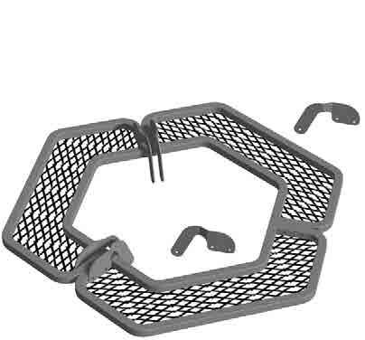
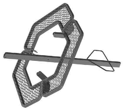
2 Section 1. Assembling Your Trophy Pod Stand. Please refer to page 3 for parts list. Please contact us at or to obtain any missing parts or if your DVD does not work.. Part 1. Platform Assembly. Step 1. Arrange the three platform sections [expanded metal side down] as shown in Figure 1. Step 2. Position a right and a left side platform bracket as shown in Figure 2. Please note the correct orientation of the brackets. Step 3. Line up the holes and bolt both brackets to the two platform sections as shown in Figure 3. Use two 2 3/4 bolts and lock nuts to secure. Hand tighten this connection. Step 4. Position a right and a left side platform bracket as shown in Figure 3. Line up the holes and bolt both brackets to the two platform sections as shown in Figure 4. Use two 2 3/4 bolts and lock nuts to secure. Hand tighten this connection. Step 5. Repeat for the last platform section (see Figure 4.) Your completed platform assembly should look like Figure 5 (bottom looking up). Step 6. Securely tighten all 6 bolts from steps 3-5. Part 2. Upper Leg Assembly. Step 1. Position the Upper Ladder Leg [has welded on rung] and the completed Platform Assembly as shown in Figure 6. Note the correct orientation - Platform brackets are pointing to the left and the ladder rungs are to the outside of the stand. Step 2. Position the Leg between the platform brackets and secure using one 1 3/4 bolt and lock nut as shown in Figure 7. Hand tighten this connection. Step 3. Position one regular Upper Leg as shown in Figure 8. Note the correct orientation. The upper bolt hole MUST be to the inside of the stand. Step 4. Secure the Upper Leg using one 1 3/4 bolt and lock nut. Hand tighten this connection. Step 5. Repeat Step 3 for the last Upper Leg. Secure using one 1 3/4 bolt and lock nut. Hand tighten this connection. Your completed assembly should look like Figure 9 and Figure 10. Part 3. Seat Assembly. Step 1. Position the Leg Base plate as shown in Figure 11. Step 2. Line up the holes and lower the Base plate onto the three leg sections as shown in Figure 11. Secure using one 1 3/4 bolt and lock nut per hole. Step 3. Securely wrench tighten the three bolts from Part 2, Steps 2-5. Step 3. Position the Seat Swivel as shown in Figure 12. Pivot one side of the Swivel to expose the bolt holes. NOTE - Leave bolts/nuts hand tight until all are started. Step 4. Bolt the Seat Swivel to the Base Plate as shown in Figure 12A. The correct order should be: 1 bolt / Metal Washer / Swivel Plate / 1/4 Nylon Spacer / Base Plate / Lock Nut (See Figure 12A). Step 5. Repeat 3 more times with three more 1 bolts, washers, spacers and lock nuts. Step 6. Wrench tighten all bolts. Step 7. Position the Seat Base Assembly as shown in Figure 13. Line up the bolt holes and secure to the Swivel using four 1 1/4 bolts (See Figure 14). Insert the bolts from the bottom and use one metal washer between the nut and the bottom of the swivel. NOTE - Leave bolts/nuts hand tight until all are started and then wrench tighten. The assembly may have to be rotated so the bolt can be inserted. Step 8. The Trophy Pod foam seat should have two sewn in loops on the front straps and snaps on the rear. Slide the front loops over the front of the Seat Base Assembly as shown in Figure 15. Snap the webbing straps over the rear cross bar. Step 9. Position the Arm Rest Tubes as shown in Figure 16. Note the correct orientation of the Arm Rest Tubes to the Seat Base. The Arm Rests should fit in the end WITHOUT the pre-punched bolt holes. Step 10. Slide the Arm Rest Tubes approximately 4 inches into the Seat Base. Secure each Tube using one self tapping screw per side as shown in Figure 17. Step 11. Line up the Backrest Bar as shown in Figure 17. Step 12. Slide one 3 1/2 carriage bolt through the Backrest Bar and the Seat Base from the inside out. Step 13. Align one Gun Rest Adjustment Bracket as shown in Figure 18. Slide the bracket over the carriage bolt and over the Seat Base tubing. Step 14. Position the Neoprene washer as shown in Figure 18. Slide the washer over the carriage bolt. Step 15. Position another Gun Rest Adjustment Bracket as shown in Figure 18. The teeth should face inward. Slide the bracket over the carriage bolt and seat it against the bracket/washer from Step 13. Step 16. Slide the Gun Rest tube onto the outside bracket. Push the carriage bolt through the pre-punched hole. Use the large knob to secure. See Figure 19. Step 17. Repeat process for the other side. The carriage bolt may have to be backed out slightly as you position the two Gun Rest Brackets and the washer between the Gun Rest tube and the Seat Base. Step 18. Position the two 12 Arm Rest Pads and the 18 Gun Rest Pad as shown in Figure 20. Secure each pad with two zip ties. The cable ties for attaching the pads are in-line cable ties: Note the correct and incorrect ways of attaching. To attach - pull the cable ties snug, cut off the excess, and rotate the clasp to the underside of the pad. Part 4. Ladder Step Assembly. Step 1. Position the Lower Ladder Section and the completed Upper Leg / Seat Assembly as shown in Figure 21. Line up the coupler plate across the joint and secure the UPPER hole using one 2 3/4 bolt and lock nut as shown in Figure 22. Be sure to run the bolt from the inside out. Step 2. Slide one Cross Brace Bracket onto a 2 3/4 bolt and insert the bolt into the LOWER bolt hole from the inside out also shown in Figure 22. Secure with a lock nut. Be sure to run the bolt from the inside out. The Brace Bracket should run side to side. Step 3. Slide one Cross Brace Bracket onto a 2 3/4 bolt and insert the bolt into the lower hole on the Ladder Section as shown in Figure 21A. Secure with a lock nut. Be sure to run the bolt from the inside out. The Brace Bracket should run side to side when completed. Step 4. The completed Ladder Leg should look like Figure 23. Part 5. Leg Assembly. Step 1. Position one Lower Leg Section (no rungs) and the completed Upper Leg / Seat Assembly as shown in Figure 24. Line up the coupler plate across the joint and secure the UPPER hole using one 2 3/4 bolt and lock nut as shown in Figure 24. Be sure to run the bolt from the inside out. Step 2. Slide one Cross Brace Bracket onto a 2 3/4 bolt and insert the bolt into the LOWER bolt hole from the inside out also shown in Figure 24A. Secure with a lock nut. Be sure to run the bolt from the inside out. The Brace Bracket should run side to side.
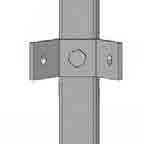
3 Step 3. Slide one Cross Brace Bracket onto a 2 3/4 bolt and insert the bolt into the lower hole on the Ladder Section as shown in Figure 25. Secure with a lock nut. Be sure to run the bolt from the inside out. The Brace Bracket should run side to side when completed. Step 4. The completed Ladder Leg should look like Figure 25. Part 6. Support Brace Assembly. Step 1. Carefully stand the completed ladder assembly up. Step 2. Position two of the support braces as shown in Figure 26. Brace A bolts to the of the UPPER brace bracket and to the of the LOWER brace bracket. Brace B bolts to the of the LOWER brace bracket and to the of the UPPER brace bracket. The braces should crisscross in the middle- one on top of the other. Step 3. Secure each brace using one 1 1/2 bolt and lock nut at each joint. Run the bolts from the inside out and HAND TIGHTEN ONLY. Step 4. Position two more support braces as shown in Figure 27. Brace C bolts to of the UPPER brace bracket and to the of the LOWER brace bracket. Brace D bolts to the of the LOWER brace bracket and to the of the UPPER brace bracket. See the inset figure for the proper brace arrangement on the UPPER and LOWER braces. Run all bolts from the inside out and leave all bolts hand tight until the final step. Secure using one 1 1/2 bolt and lock nut at each joint. See Figure 27A for proper brace / bolt arrangement for the upper mounting locations. Braces should be staggered at each location - one on the outside, one on the inside. See Figure 27B for proper brace / bolt arrangement for the lower mounting locations. Step 5. Position the last two support braces as shown in Figure 28. Brace E bolts to the of the UPPER brace bracket and to the of the LOWER brace bracket. Brace F bolts to the of the LOWER brace bracket and to the of the LOWER brace bracket. Run all bolts from the inside out. Secure using one 1 1/2 bolt and lock nut at each joint. Step 6 Securely tight ALL BOLTS from Step 1-5! Step 3. Tie your gun or bow to a pull-up rope and then tie the other end to your belt or around the top of the stand where you can reach it. Step 4. Carefully climb up the steps - ALWAYS MAINTAIN THREE POINTS OF CONTACT WHILE CLIMBING. Once you reach the seat, step up onto the platform and swivel the seat so it is facing you. Carefully sit down. Step 5. Loosen the large knobs on the Gun Rest and bring the rest up and over your head to your desired shooting position. Step 6. Pull up your gun or bow and begin hunting. Section 3. Maintenance and Care of Your Treestand. Because of the quality construction techniques used in manufacturing, your Summit Trophy Pod is very durable under normal hunting conditions. However, since all hunting equipment that is exposed to the elements requires some maintenance and care, the following guidelines for caring for your treestand should be used. DO NOT leave your treestand outdoors when it is not being used. Any tubing that is allowed to fill with rainwater and freeze WILL rupture or burst. DO NOT use your treestand if this happens. If your stand is exposed to the elements, it will be necessary to cover the seat or remove it to prevent rain and moisture from saturating the material. This will extend the life of the seat material as well as make it more comfortable the next time it is used. The powder coat finish that is applied at the factory is very durable and should need touch ups only in areas of heavy wear or accidental impact. Should you damage any part of your Summit Trophy Pod, contact your nearest authorized Summit dealer or the factory to obtain the proper corrective action procedure and/or replacement parts for the stand. Unauthorized repairs, modifications, or alterations will void the warranty and could degrade the integrity of the stand. You must perform periodic inspections of the treestand for damage. WARNING: DO NOT use the stand if ANY obvious or suspected damage is observed. CAUTION: Look for nicks, gouges, cuts, cracks, bends, corrosion or similar damage that can be the result of improper use or accidental damage. For instance, this could occur if someone else used the treestand without knowledge of its proper use, or if the stand were dropped, hit by a motor vehicle or subject to corrosive conditions, etc. Summit Pod Stands have the highest structural integrity by design, material selection and manufacturing techniques, but as its owner, only your continued care will assure trouble free performance. When the above-mentioned guidelines are followed, your Summit Trophy Pod will provide years of successful hunting. Section 2. Use of the Trophy Pod. WARNING: THE TROPHY POD IS DESIGNED TO WORK ON LEVEL GROUND ONLY. MAKE SURE THAT THE LOCATION YOU CHOOSE IS FREE OF ROCKS OR OTHER DEBRIS. WARNING: THE GUN REST ASSEMBLY IS NOT TO BE USED AS A HAND HOLD WHILE CLIMBING INTO THE STAND!!! ALWAYS PIVOT THE GUN REST BEHIND YOU BEFORE YOU EXIT THE STAND! Summit products are manufactured under one or more of the following US Patents: 5,937,969; 5,971,104; 5,975,242; 5,979,603; 6,125,966; 6,182,792; 6,397,973; D,417,011; D,420,147 Summit Bucksteps and RapidClimb Stirrups are Patent Pending DO NOT USE THE GUN REST AS A FOOTREST! Step 1. Select a suitable position for the Trophy Pod - MAKE SURE THE GROUND IS LEVEL! and MAKE SURE YOU DO NOT PLACE A LEG ON A ROCK OR STUMP! Step 2. Secure each leg using the supplied spikes. Insert the Spike into the opening on the leg and push it down to secure as shown in Figure 29.


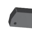
4 BOX CONTENTS PN Description QTY Seat Base Assembly Leg Base Plate Platform Section Upper Ladder Leg Lower Ladder Leg Lower Leg Upper Leg Right Side Platform Bracket Left Side Platform Bracket Cross Brace Bracket Coupler Plate Cross Brace Arm Rest Tube Gun Rest Tube Backrest Bar Spike Foam Seat Accessory Packet ACCESSORY PACKET CONTENTS PN Description QTY Arm Pad Gun Rest Pad Cable Tie 7 Written instructions for this Stand 2007 DVD Hardware Kit HARDWARE KIT TROPHY-POD (continued) PN Description QTY /4 Nylon Spacer /4 Metal Washer /4 Lock Nut (1/4-20) /2 Carriage Bolt (1/4-20) Adjustment Bracket HARDWARE KIT TROPHY-POD PN Description QTY /4 Bolt (5/16-18) Knob /4 Bolt (5/16-18) /2 Bolt (5/16-18) Neoprene Washer Centerlock Nuts (5/16-18) Self Tapping Screws Bolt (1/4-20) /4 Bolt (1/4-20) 4 Tools Required 1/2 Socket and Ratchet 1/2 Wrench 7/16 Socket 7/16 Wrench Phillip s Head Manual or Powered Screw Driver Side Cutters or Knife for Trimming Cable Ties


5 Figure 1 Figure 2 Figure 3 Figure 4 Figure 5 Figure 6


6 Figure 7 Figure 8 1 3/4 Bolt and Lock Nut Figure 11 Figure /4 Bolt and Lock Nut Figure 14 Figure 15 Lock Nut Sewn Loop Snaps Metal Washer 1 1/4 Bolt Bolt Hole


7 Figure 9 Figure /4 Bolt and Lock Nut Figure 12A Figure 13 Metal Washer 1 Bolt 1/4 Spacer Lock Nut Figure 16 Figure 17 Self Tapping Screw Bolt Hole


8 Figure 18 Back Rest Figure 19 Neoprene Washer Carriage Bolt Gun Rest Tube Knob Gun Rest Adjustment Brackets Cross Brace Bracket Figure 21 Lower Ladder Section Lower Bolt Hole Upper Bolt Hole Upper Leg / Seat Assy. Figure 21A Figure 23


9 18 Pad Figure 20 Incorrect Correct 12 Pads Figure 22 Upper Bolt Hole Figure 24 Figure 24A


10 Figure 25 Figure 27 Upper Bracket Arrangement D C Figure 27A Figure 29 Figure 27B Lower Bracket Arrangement Spike
11 Figure 26 B A Figure 28 F E Cut Along Line Cut Along Line Warranty Card for Summit Trophy Pod (82038) Owners Name: Street Address: City: State: ZIP: Phone: ( ) Date Purchased: Purchased From (Dealer Name): Price $: Your heard about us through: Magazine Advertisement Video Friend Summit Catalog Other Please Explain: You can also register your warranty card on line at:
12 Limited Warranty (A) Warranty Summit Treestands, LLC (Summit) warrants to the original retail purchaser that all products manufactured by it are free from defects in material and manufacture at the time of shipment for sixty (60) months from the date of purchase. Summit will repair or replace any part found defective if the unit claimed to be defective shall be returned to Summit, postage prepaid, within the warranty period. This warranty shall not apply to any product which has been subjected to misuse; misapplication; neglect (including but not limited to improper maintenance); accident; improper installation; modification (including but not limited to use of unauthorized parts or attachments); adjustment or repair. THE FOREGOING IS IN LIEU OF ALL OTHER WARRANTIES, WHETHER EXPRESS OR IMPLIED (INCLUDING THOSE OF MERCHANTABILITY AND FITNESS OF ANY PRODUCT FOR A PARTICULAR PURPOSE), AND OF ANY OTHER OBLIGATION OF LIABILITY ON THE PART OF THE COMPANY. (B) Limitation of Liability It is expressly understood that Summit s liability for its products, whether due to breach of warranty, negligence, strict liability, or otherwise, is limited to the repair of the product, as stated above, and Summit will not be liable for any other injury, loss, damage, or expense, whether direct or consequential, including but not limited to loss of use, income, profit, or damage to material, arising in connection with the sale, installation, use of, inability to use, or the repair or replacement of Summit s products. Summit reserves the right to make alterations or modifications in its products at any time, which in its opinion, may improve the performance and efficiency of the product. It shall not be obligated to make such alterations or modifications to products already in service. Please fill out the warranty card on the back of these instructions and return to: SUMMIT Treestands, LLC. 715 Summit Dr. Decatur, AL (STLLC 2007)
X-Pod - Instruction Booklet
 X-Pod - Instruction Booklet - 2007 You MUST also view the enclosed DVD BEFORE using your new stand!! Weight Limit: 300 lbs. Total. DO NOT EXCEED THIS LIMIT! READ ME FIRST!!! Please read carefully BEFORE
2009 Predator Pod INSTRUCTIONS WARNING PN WEIGHT LIMIT 300 LBS. X 1 TOTAL** DO NOT EXCEED THIS LIMIT! (** Includes all gear)
") ! INSTRUCTIONS WARNING You must fully read, understand and follow these warnings and instructions (written and video)! Failure to follow these instructions may cause serious injury or death!! You MUST
! INSTRUCTIONS WARNING You must fully read, understand and follow these warnings and instructions (written and video)! Failure to follow these instructions may cause serious injury or death!! You MUST
Summit Classic Deluxe Tripod 12 Leg Kit PN WARNING
 Summit Classic Deluxe Tripod 12 Leg Kit PN 81519 You must fully read, understand and follow these warnings and instructions (written and video) Failure to follow these instructions may cause serious injury
Two Man Tripod. Summit Deluxe INSTRUCTIONS WARNING PN WEIGHT LIMITS. DO NOT EXCEED THIS LIMIT! (* Includes all gear)
") ! INSTRUCTIONS WARNING You must fully read, understand and follow these warnings and instructions (written and video)! Failure to follow these instructions may cause serious injury or death!! You MUST
! INSTRUCTIONS WARNING You must fully read, understand and follow these warnings and instructions (written and video)! Failure to follow these instructions may cause serious injury or death!! You MUST
Summit Classic Deluxe Tripod 16 Leg Kit PN WARNING
 ! Summit Classic Deluxe Tripod 16 Leg Kit PN 81521 WARNING You must fully read, understand and follow these warnings and instructions (written and video)! Failure to follow these instructions may cause
WARNING. Summit Deluxe Tripod Stand PN DO NOT EXCEED THIS LIMIT! (* Includes all gear) Stand minimum and maximum tree size: 8-20 diameter
 Stand minimum and maximum tree size: 8-20 diameter") Summit Deluxe Tripod Stand PN 82058 2012 Summit Treestands, LLC 715 Summit Dr. Decatur, AL 35601 (256) 353-0634 info@summitstands.com! WARNING You MUST also view the enclosed DVD BEFORE using your new
Summit Deluxe Tripod Stand PN 82058 2012 Summit Treestands, LLC 715 Summit Dr. Decatur, AL 35601 (256) 353-0634 info@summitstands.com! WARNING You MUST also view the enclosed DVD BEFORE using your new
Models 2230 and 2240
 Models 2230 and 2240 Overview... 2 Tools Needed... 2 Hardware...3 Assembly... 4-13 Installation... 14 Drawer Removal... 15 Operation... 15 Maintenance... 15 Accessories... 16 Limited Warranty... 16 Perform
Owner s Manual & Safety Instructions
 Owner s Manual & Safety Instructions Save This Manual Keep this manual for the safety warnings and precautions, assembly, operating, inspection, maintenance and cleaning procedures. Write the product s
LOCKDOWN 21 2-MAN Ladder Stand
 WE ARE HUNTERS LOCKDOWN 21 2-MAN Ladder Stand MODEL RE650 Maximum Height 21' to shooting rail Maximum Field Rating 500 lbs; no more than 300 lbs per person. Tree Diameter Range 12" to 20" Wear Your Harness!
INCLUDES BENCH MODELS:
 SHOOTING BENCH OWNERS MANUAL & USAGE INSTRUCTIONS INCLUDES BENCH MODELS: AR02-B The Deluxe Shooting Bench AR03-B The Swivel Action Shooting Bench AR02-B DELUXE SHOOTING BENCH WARNING: Do not use without
Tilting Flat Panel Wall Mount Installation Guide
 Tilting Flat Panel Wall Mount Installation Guide Model: A580TM Easy installation Built-in level for easy positioning Safety bolts lock the TV on the mount Easy to adjust tilt angles: +5 to -15 degrees
Tilting, Swiveling & Rotating Flat Panel Wall Mount
 Tilting, Swiveling & Rotating Flat Panel Wall Mount Model: VXA980TC +5 to -5 +5 to -5 Supports most 0-80 Flat Panel TVs Maximum Weight Capacity: 32 lbs. Supports VESA Sizes up to 600x500 For technical
RE741 Perimeter Ladder Pod
 Operator's Manual RE741 Perimeter Ladder Pod PRODUCT MEETS INDUSTRY STANDARDS RECOGNIZED BY PARTICIPATING MEMBER Get parts online at www.huntriversedge.com P/N: 17781 REV3: 03/29/16 2016 RETI All Rights
RE703 Outpost Tower. Operator's Manual. Maximum Field Rating lbs. OMRE70309 ECN: REV2: 02/28/ RETI. All Rights Reserved.
 RE703 Outpost Tower Maximum Field Rating - 500 lbs. Certified to TMA Standards by an Independent Testing Laboratory Get parts online at www.huntriversedge.com OMRE70309 ECN: 10325 REV2: 02/28/14 2014 RETI.
00108/00110 INSTRUCTION MANUAL
 00108/00110 INSTRUCTION MANUAL Removable and Adjustable Mudflap System IMPORTANT! Please Read this Instruction Booklet prior to assembly of your Rock Tamer Kit. IMPORTANT! Exhaust Systems Note: Any modifications
OPERATORS MANUAL WEEKENDER STEEL LADDER RACK
 OPERATORS MANUAL WEEKENDER STEEL LADDER RACK WWW.WEATHERGUARD.COM MODELS 1450 & 1475 1475 Shown INSTALLATION TIME Approximate installation time: 60 minutes (depending on truck equipment installation experience
Manual Carton Closing Staplers
 Operator s Manual Manual Carton Closing Staplers SHB00-A Item No. 6400 -/8" Crown Carton Closing Stapler 5/8" and /4" (5mm and 8mm) Ask for Genuine INTERCHANGE A58 and A4 Staples SHB50-C Item No. 640 -/4"
Tilting & Swiveling Plasma/LCD Flat Panel Wall Mount Installation Guide Model: A380SM
 Tilting & Swiveling Plasma/LCD Flat Panel Wall Mount Installation Guide Model: A380SM Easy installation Built-in level for easy positioning Corrective leveling adjustments after installation Forward /
HuntRiversEdge.com INSTRUCTIONS
 INSTRUCTIONS Universal Treestand Canopy Model RE750 OMRE75009 Rev. 12/09/08 2009 Rivers Edge Treestands, Inc. All Rights Reserved. Rivers Edge Treestand Canopy s are engineered with you the hunter in
Models 2130 and 2140
 Models 2130 and 2140 Overview... 2 Tools Needed... 2 Hardware... 2 Assembly... 3-10 Installation...11 Operation... 11 Maintenance... 12 Accessories...12 Limited Warranty... 12 Perform the following sequence
PATRIOT DOCKS ASSEMBLY INSTRUCTIONS
 6/1/2008 PATRIOT DOCKS ASSEMBLY INSTRUCTIONS Congratulations on your new Patriot Dock purchase. This manual contains instructions to assemble basic dock configurations for use at typical shoreline application.
Installation Instructions Cage Kit JK Unlimited (4-Dr) Part # 76902
 Part # 76902") Please read instructions entirely before installing this product. Drilling is required to install this part. Parts Included Qty Parts Included Qty Driver Front Upright 1 Pass Side Drill Template (7289)
Please read instructions entirely before installing this product. Drilling is required to install this part. Parts Included Qty Parts Included Qty Driver Front Upright 1 Pass Side Drill Template (7289)
Sunset Swings By Health in Motion, LLC
 Sunset Swings By Health in Motion, LLC Model 421 Lounge Swing Assembly and Operation Manual Record Serial Number Here www.sunsetswings.com by Health In Motion, LLC. 11/6/2009 421 Owners Assembly and Operation
Models 2030 and 2040
 Models 2030 and 2040 Overview... 2 Tools Needed... 2 Hardware... 2 Assembly... 3-8 Installation... 9 Operation... 9 Maintenance... 10 Accessories... 10 Limited Warranty... 10 Document # 101290 0607 Printed
MFJ-1835K34 40,30 METER ADD ON KIT FOR THE MFJ-1835 COBWEB ANTENNA INSTRUCTION MANUAL. CAUTION: Read All Instructions Before Operating Equipment
 MFJ-1835K34 40,30 METER ADD ON KIT FOR THE MFJ-1835 COBWEB ANTENNA INSTRUCTION MANUAL CAUTION: Read All Instructions Before Operating Equipment 300 Industrial Park Road Starkville, MS 39759 USA Tel: 662-323-5869
Models 2130 and 2140
 Models 2130 and 2140 Overview... 2 Tools Needed... 2 Hardware... 2 Assembly... 3-10 Installation...11 Operation... 11 Maintenance... 12 Accessories...12 Limited Warranty... 12 Printed in USA 2007 Perform
Please Do Not Return This Product To The Store!
 MODEL NOS. T8512 TOURNAMENT SERIES 3 TABLE TENNIS TABLE OWNER'S MANUAL 1. Read this manual carefully before starting assembly. Read each step completely before beginning each step. 2. Some smaller parts
Owner s Manual LSP38 38 Lawn Sweeper
 Owner s Manual LSP38 38 Lawn Sweeper Manual Contents Safety Instructions Assembly Operation Maintenance Parts Warranty 2 4-13 2 11 14-15 16 Your Lawn Sweeper Congratulations on your purchase of a new Precision
15 Planer Stand. Model Due to continuing improvements, actual product may differ slightly from the product described herein.
 15 Planer Stand Model 96316 Assembly And Operation Instructions Due to continuing improvements, actual product may differ slightly from the product described herein. 3491 Mission Oaks Blvd., Camarillo,
Model Assembly & Operating Instructions
 30 SHEAR BRAKE ROLL Model 05907 Assembly & Operating Instructions Diagrams within this manual may not be drawn proportionally. Due to continuing improvements, actual product may differ slightly from the
Owner s Manual ODYSSEY BENCH MODEL. O4100B shown REV E. Southern Avenue, Phoenix, AZ USA Workhorseproducts.
 Owner s Manual ODYSSEY BENCH MODEL O4100B shown 67-1375 REV 218 3730 E. Southern Avenue, Phoenix, AZ 85040 USA 800-778-8779 Workhorseproducts.com 1 Table of Contents I. Introduction & Safety Information.
M ACS Instructions
 APPLICABLE MODELS: Nissan Frontier 2005 and up short bed with Utili-Trak mounting rails PACKAGE CONTENTS 00-0060-M-01-1205 ACS Instructions Leitner Designs 25675 Taladro Circle Unit E Mission Viejo, CA
Installation and Assembly: Articulating Swivel Arm for 37" - 60" Flat Panel Displays
 Installation and Assembly: Articulating Swivel Arm for 37" - 60" Flat Panel Displays Models: PLA60, PLA60-S, PLAV60, PLAV60-S Max UL Load Capacity: 175 lb (79 kg) 2300 White Oak Circle Aurora, Il 60502
One-Man Ladder Stands
 One-Man Ladder Stands ONSET XT Model RE626 ONSET Model RE625 INCLUDES MODEL #'s: RE625, Onset RE626, Onset XT Wear Your Harness! WARNING NEVER ASCEND OR DESCEND LADDER WITHOUT TIE-OFF ROPES SECURELY HOLDING
Please Do Not Return This Product To The Store!
 MODEL NO. T8176 QUICK SERVE 3000 TABLE TENNIS TABLE OWNER'S MANUAL 1. Read this manual carefully before starting assembly. Read each step completely before beginning each step. 2. Some smaller parts may
COMPETITOR WM-203 COMBO BENCH
 NOTE: Please read all instructions carefully before using this product Table of Contents Safety Notice Hardware Identifier COMPETITOR WM-203 COMBO BENCH Assembly Instruction Exploded Diagram Parts List
SawStop. T-GlideTM. Fence System- Professional Series II OWNER S MANUAL
 SawStop T-GlideTM Fence System- Professional Series II OWNER S MANUAL Warranty SawStop warrants to the original retail purchaser of a new T-Glide Fence System - Professional Series II from an authorized
Owner s Manual & Safety Instructions
 Owner s Manual & Safety Instructions Save This Manual Keep this manual for the safety warnings and precautions, assembly, operating, inspection, maintenance and cleaning procedures. Write the product s
20 Ton HYDRAULIC SHOP PRESS
 20 Ton HYDRAULIC SHOP PRESS Stock Number W41063 OWNER S MANUAL WARNING! It is the owner and/or operators responsibility to study all WARNINGS, operating, and maintenance instructions contained on the product
MARCY CLASSIC MCB-252 COMBO BENCH W/120 lbs Weight Set
 NOTE: Please read all instructions carefully before using this product Table of Contents Safety Notice Hardware Identifier Assembly Instruction MARCY CLASSIC MCB-252 COMBO BENCH W/120 lbs Weight Set Exploded
Installation Manual Roof Zone Ladder Rack
 Installation Manual Roof Zone Ladder Rack 102113,E1346 Installation Time: About 90 minutes. Depending on truck and Do-it-Yourself experience level Tools Required: Electric Drill with 1/2 Chuck 1/2 & 7/32
Please Do Not Return This Product To The Store!
 MODEL NOS. T81 TABLE TENNIS TABLE OWNER'S MANUAL 1. Read this manual carefully before starting assembly. Read each step completely before beginning each step.. Some smaller parts may be shipped inside
LifeGear G1 /HOME GYM ITEM NO.: 63100
 LifeGear G1 /HOME GYM ITEM NO.: 63100 OWNER S MANUAL IMPORTANT: Read all instructions carefully before using this product. Retain this owner s manual for future reference. The specifications of this product
Stand Aid User Manual REF: 1914
 Stand Aid User Manual REF: 1914 The Chattanooga Group Alliance TM Stand Aid is a manual standing aid to allow patients to assist themselves in preparation for transport. Patients qualified to use the Stand
Installation Procedures 2015 Roush Mustang Stage 1 & 2. SNS 62b
 Installation Procedures 2015 Roush Mustang Stage 1 & 2 SNS 62b Warning: Please read directions completely before starting. If you have any questions please contact BMPP before beginning your installation.
GB-AVSTOR5 Ceiling Equipment Storage Box with Pipe Coupler
 Ceiling Equipment Storage Box with Pipe Coupler INSTALLATION INSTRUCTIONS CREATING POSITIVE CUSTOMER EXPERIENCES 9534-500-021-00 Contents Weight Limit... 2 Warning Statements... 2 Installation Tools...
OWNER'S MANUAL. Please Do Not Return This Product To The Store!
 MODEL NO. T8190SA TABLE TENNIS TABLE OWNER'S MANUAL 1. Read this manual carefully before starting assembly. Read each step completely before beginning each step.. Some smaller parts may be shipped inside
Dual Arm Tilt LCD Mount
 Installation Manual model # 51324 M o u n t i n g S y s t e m s Dual Arm Tilt LCD Mount Fits Displays 13 to 32 Supports Up to 50 lbs (23 kgs) Projection from Wall from 3 to 17 Meets VESA Standards 50/75/100,
Specifications. Important Safety Information
 Specifications Tire Rim Capacity 4 to 12 Rim Height 16 (2) Bead Breaker Handles 21 Long Includes Aluminum Centering Cone (2) Nylon Spacers Important Safety Information 1. Do not exceed max. tire capacity.
COMPETITOR CB-610 STANDARD BENCH
 NOTE: Please read all instructions carefully before using this product Table of Contents Safety Notice COMPETITOR CB-610 STANDARD BENCH Hardware Identifier Assembly Instruction Exploded Diagram Parts List
Please read and understand the OnBoard Timpani Cart Owner s Manual before using the Timpani Cart.
 Assembly and Owner s Manual OnBoard Timpani Cart Performance Position Towing Position CONTENTS Important User Information...........................2 General......................................2 Manufacturer.................................2
READ CAREFULLY - FAILURE TO FOLLOW INSTRUCTIONS AND SAFETY RULES MAY RESULT IN SERIOUS INJURY
 Owner s Manual LSV50120B LS5000B leg bundle LS5021B post bundle LS5022B cradle bundle V50120B straight LS5003B spreader bundle LS5004B bunk bundle LS4005B accessory box LS2005B wheel LS5007B diag bundle
ATTENTION: PLEASE READ AND UNDERSTAND ALL INSTRUCTIONS AND WARNINGS BEFORE ASSEMBLING, INSTALLING OR USING THIS PRODUCT.
 INSTALLATION MANUAL Models 96111-3-02 & 96511-3-02 Bulkheads for 2014 and Later Ford Transit Connect Vans ATTENTION: PLEASE READ AND UNDERSTAND ALL INSTRUCTIONS AND WARNINGS BEFORE ASSEMBLING, INSTALLING
Installation Procedures 2018 Mustang GT & EcoBoost SNS 135
 Installation Procedures 2018 Mustang GT & EcoBoost SNS 135 Warning: Please read directions completely before starting. If you have any questions, please contact BMPP before beginning your installation.
Instruction Sheet D-CPU. Secure CPU Holder
 Instruction Sheet D-CPU Secure CPU Holder I-00457 Rev A PARTS LIST NOTE: Select Security Components when a more secure application is desired. Mounting Track with Mounting Tape Security Bracket Assembly
P4263TP. Installation Guide. Low-Profile Tilting Portrait Mount for Flat-Panels
 Low-Profile Tilting Portrait Mount for Flat-Panels 1321 S. State College Blvd., Fullerton, CA 92831 USA Weight Limit Maximum Flat Panel Weight: 175 lbs. Warning Statements THE WALL STRUCTURE MUST BE CAPABLE
VAN STORAGE SOLUTIONS FOR THE WAY YOU WORK
 WWW.WEATHERGUARD.COM VAN STORAGE SOLUTIONS FOR THE WAY YOU WORK Weather Guard / KNAACK 420 E. Terra Cotta Ave. Crystal Lake, IL 60014 USA 800-456-7865 (Toll Free) 800-334-2981 (Fax) Knaack.OrderEntry@wernerco,.com
Owner s Manual GS2010 Garden Seeder/Fertilizer. Caution: Carefully read all Rules and Instructions for Safe Operation.
 Manufacture s Limited Warranty for The limited warranty set forth below is given by Precision Products, Incorporated with respect to new merchandise purchased and used in the United States, its possessions
INSTALLATION QUICK ADJUST RELOCATOR FOR TOUR-PAK 8973
 FOR TOUR-PAK 8973 PARTS INCLUDED 1 Base Plate Assembly 1 Right Side Extruded Slider Assembly 1 Left Side Extruded Slider Assembly 1 Filler Panel 1 Hardware Kit 1 Stop Block 2 1/4-20 x 1/2" Hex Head Cap
ATV STORM CHASER PLOW PUSH TUBE KIT
 ATV STORM CHASER PLOW PUSH TUBE KIT P/N 33-0070 OWNER S MANUAL Application MID-BODY ATV MOUNT NO. 15-XXXX, ALL MOUNT NO. 15-0050 ATTENTION DEALER: CUSTOMER MUST RECEIVE A COPY OF THIS MANUAL AT THE TIME
PLOW MOUNT KIT FOR POLARIS RANGER P/N ASSEMBLY / OWNERS MANUAL
 PLOW MOUNT KIT FOR POLARIS RANGER P/N 34-3010 ASSEMBLY / OWNERS MANUAL Application PLOW PUSH FRAME NO. 34-0000 or 34-0070 Before you begin, please read these instructions and check to be sure all parts
Planishing hammer stand For use with SKU Planishing hammer
 Planishing hammer stand For use with SKU 94847 Planishing hammer Model 96300 Assembly And Operation Instructions Please Note: Planishing Hammer not included with Stand. Due to continuing improvements,
Installation Procedures 2015 Corvette C-7 Z06 With Carbon Fiber Kit SNS 50a
 Installation Procedures 2015 Corvette C-7 Z06 With Carbon Fiber Kit SNS 50a Warning: Please read directions completely before starting. If you have any questions please contact BMPP before beginning your
Installation Procedures For Corvette Basic/C-6 SNS 28
 Installation Procedures For 2005-2013 Corvette Basic/C-6 SNS 28 Warning: Please read directions completely before starting. If you have any questions please contact BMPP before beginning your installation.
Installation Procedures Dodge Charger R/T Scat Pak, SRT/Hellcat. SNS 66a
 Installation Procedures 2015-2017 Dodge Charger R/T Scat Pak, SRT/Hellcat SNS 66a Warning: Please read directions completely before starting. If you have any questions please contact BMPP before beginning
One Shelf, Wall Mounted A/V Component Stand Installation Guide Model: EX101SS
 One Shelf, Wall Mounted A/V Component Stand Installation Guide Model: EX0SS For technical assistance or troubleshooting please call -855-994-3832. This product is intended for use only with Audio/Video
Installation Procedures Maserati Gran Turismo Sport SNS 85
 Installation Procedures 2012-2017 Maserati Gran Turismo Sport SNS 85 Warning: Please read directions completely before starting. If you have any questions please contact BMPP before beginning your installation.
PAM-200 Universal Projector Mount
 INSTALLATION MANUAL PAM-200 Universal Projector Mount Sony Electronics 16540 West Bernardo Drive San Diego, CA 92127 www.sony.com IN-PAM200.R0 Table of Contents Parts List...- 3 - Installation Tools...-
OnBoard Bass Drum/Gong Cart
 Assembly and Owner s Manual OnBoard Bass Drum/Gong Cart CONTENTS Important User Information...................................................................2 Safety...................................................................................3
MODEL T28000 HEAVY-DUTY MOBILE BASE INSTRUCTIONS
 MODEL T28000 HEAVY-DUTY MOBILE BASE INSTRUCTIONS For questions or help with this product contact Tech Support at (570) 546-9663 or techsupport@grizzly.com Introduction Your new Model T28000 Heavy-Duty
ATV CULTIVATOR OWNER S MANUAL
 ATV CULTIVATOR OWNER S MANUAL WARNING: Read carefully and understand all ASSEMBLY AND OPERATION INSTRUCTIONS before operating. Failure to follow the safety rules and other basic safety precautions may
Important safety considerations
 Important safety considerations This product is intended for use by children not less than 2 years of age. Warning: possible problems of entrapment could occur if used by children under 2 years of age.
INSTALLATION INSTRUCTIONS
 CREATING POSITIVE CUSTOMER EXPERIENCES INSTALLATION INSTRUCTIONS Universal Low Profile Tilt Mount for 42 to 63 Flat Panels NORTH AMERICA 3130 East Miraloma Avenue Anaheim, CA 92806 USA USA and Canada Phone:
ATTENTION: PLEASE READ AND UNDERSTAND ALL INSTRUCTIONS AND WARNINGS BEFORE ASSEMBLING, INSTALLING OR USING THIS PRODUCT.
 VAN STORAGE SOLUTIONS FOR THE WAY YOU WORK TM INSTALLATION MANUAL BULKHEAD Model Number 96101-3-01 ATTENTION: PLEASE READ AND UNDERSTAND ALL INSTRUCTIONS AND WARNINGS BEFORE ASSEMBLING, INSTALLING OR USING
Installation Procedures For 2013 Mustang V-6 and 5.0
 Installation Procedures For 2013 Mustang V-6 and 5.0 Warning: Please read directions completely before starting. If you have any questions please contact BMPP before beginning your installation.. Also
9 PIECE TUNGSTEN CARBIDE HOLE SAW KIT. Model 90721
 9 PIECE TUNGSTEN CARBIDE HOLE SAW KIT Model 90721 Set up And Operating Instructions Diagrams within this manual may not be drawn proportionally. Due to continuing improvements, actual product may differ
READ CAREFULLY - FAILURE TO FOLLOW INSTRUCTIONS AND SAFETY RULES MAY RESULT IN SERIOUS INJURY
 LSV30108C LS5002C cradle bundle 108 LS5004B bunk bundle LSV40108C LS5002C cradle bundle 108 LS5004B bunk bundle LS5007B diagonal bundle LSV30120C LS5012C cradle bundle 120 LS5004B bunk bundle LSV40120C
READ CAREFULLY - FAILURE TO FOLLOW INSTRUCTIONS AND SAFETY RULES MAY RESULT IN SERIOUS INJURY
 Owner s Manual LSV50120B LS5000B leg bundle LS5021B post bundle LS5022B cradle bundle V50120B straight LS5003B spreader bundle LS5004B bunk bundle LS4005B accessory box LS2005B wheel LS5007B diag bundle
LM621 Landmark 10' 450 Tower
 LM621 Landmark 10' 450 Tower Assembly Time 2-4 Hours PRODUCT MEETS INDUSTRY STANDARDS RECOGNIZED BY PARTICIPATING MEMBER Get parts online at www.huntriversedge.com P/N: 391 REV1: 02/06/18 2018 RETI All
Security Products & Services...That Never Sleep. Sur-Lock. I/O 2000L Family of Exit Control Alarm Locks. Installation Instructions
 Security Products & Services...That Never Sleep Sur-Lock I/O 2000L Family of Exit Control Alarm Locks Installation Instructions IMPORTANT It is important that you read and follow these instructions carefully.
SAFETY. Injury hazard
 SAFETY Installation Guidelines Your safety and the safety of others is very important. In order to help you make informed decisions about safety, we have provided installation instructions and other information.
PLOW MOUNT KIT FOR CAN-AM COMMANDER P/N ASSEMBLY / OWNERS MANUAL. Application PLOW PUSH FRAME NO or
 PLOW MOUNT KIT FOR CAN-AM COMMANDER P/N 34-7010 ASSEMBLY / OWNERS MANUAL Application PLOW PUSH FRAME NO. 34-0000 or 34-0070 Before you begin, please read these instructions and check to be sure all parts
READ CAREFULLY - FAILURE TO FOLLOW INSTRUCTIONS AND SAFETY RULES MAY RESULT IN SERIOUS INJURY
 LSV30108B LS5002B cradle bundle 108 LS5004B bunk bundle LSV40108B LS5002B cradle bundle 108 LS5004B bunk bundle LS5007B diagonal bundle LSV30120B LS5012B cradle bundle 120 LS5004B bunk bundle LSV40120B
31082 INSTALLATION INSTRUCTIONS
 08 INSTALLATION INSTRUCTIONS Safety glasses should be worn at all times while installing this product. YEARS: 07-CURRENT MAKE: HONDA MODEL: RIDGELINE STYLE: TRUCK WARNING: NEVER EXCEED YOUR VEHICLE MANUFACTURER'S
Check us out on-line! Installation Instructions
 Installation Instructions 2 OPTIONAL ACCESSORIES Order Quantum Rack Accessories Online at www.dawsbetterbuilt.com Cargo Lock Kit Secure Your Load Cargo Locks can easily be installed and adjusted left or
PLOW MOUNT KIT FOR KAWASAKI TERYX, YAMAHA RHINO P/N ASSEMBLY / OWNERS MANUAL
 PLOW MOUNT KIT FOR KAWASAKI TERYX, YAMAHA RHINO P/N 34-2025 ASSEMBLY / OWNERS MANUAL Application PLOW PUSH FRAME NO. 34-0000 or 34-0070 Before you begin, please read these instructions and check to be
Outdoor Water Solutions, Inc. Small Backyard Windmill. Installation Manual
 Outdoor Water Solutions, Inc. Small Backyard Windmill Installation Manual Customer Service: 1-866-471-1614 Website: www.outdoorwatersolutions.com Springdale, Arkansas 72764 Phone: 1-866-471-1614 Fax: 1-479-750-9178
Usage and Assembly Instructions
 Instructions #1037447 Product #795234 Revision D Usage and Assembly Instructions Rear Fork (Buttstock) Rear Fork Lock Knob Rail Lock Knob Front Fork (Forend) Rails Tilt Friction Knob Rail Extension Locks
Costco High Wire Assembly Instruc ons & Owner's Manual
 2254 Costco High Wire Assembly Instruc ons & Owner's Manual Important! Read this manual completely through before assembly and use. Consumer assistance Toll free If you need to order replacement parts
TABLE OF CONTENTS DESCRIPTION. Safety Instructions Assembly Operation... 7
 TABLE OF CONTENTS DESCRIPTION PAGE Warranty... 1 Safety Instructions... 2 Assembly... 3 Operation... 7 #360 Grain Cleaner Drawings... 8 #360 Grain Cleaner Parts List... 10 Utility Auger Option Drawing...
GroundControl. Follow instructions contained in this manual. Incorrect installation could result in serious injury or damage to property.
 GroundControl TM use supplied hardware Use only hardware supplied in your GroundControl kit or supplied by an authorized YAKIMA dealer. Use of unauthorized parts in the GroundControl system could result
Installation Procedures Dodge Challenger SXT, R/T, Scat Pak, SRT & Hellcat SNS 1a
 Installation Procedures 2015-2017 Dodge Challenger SXT, R/T, Scat Pak, SRT & Hellcat SNS 1a Warning: Please read directions completely before starting. If you have any questions, please contact BMPP before
INSTALLATION MANUAL WEEKENDER STEEL LADDER RACK
 TRUCK STORAGE SOLUTIONS SECURING YOUR REPUTATION INSTALLATION MANUAL WEEKENDER STEEL LADDER RACK STEEL & ALUMINUM SIDE BOX WITH PACK RAT DRAWER UNITS MODELS ATTENTION: PLEASE READ AND UNDERSTAND ALL INSTRUCTIONS
Installation Procedures Jaguar XF SNS 92
 Installation Procedures 2016-2017 Jaguar XF SNS 92 Warning: Please read directions completely before starting. If you have any questions please contact BMPP before beginning your installation. Also please
Two-Man Ladder Stands
 Two-Man Ladder Stands STANDARD 2-MAN Model RE629 INCLUDES MODEL #'s: RE629, Standard 2-Man RE633, Twoplex RE634, Relax 2-Man TWOPLEX Model RE633 Wear Your Harness! Get parts online at www.huntriversedge.com
SawStop. Contractor Fence Assembly OWNER S MANUAL. Model CNS-SFA
 Contractor Fence Assembly OWNER S MANUAL Model CNS-SFA Warranty warrants to the original retail purchaser of the Contractor Fence Assembly accompanying this manual that the fence assembly will be free
accidents which arise due to nonobservance and the safety information herein. SPECIFICATIONS
 7 TON ELECTRIC LOG SPLITTER Model: 05620 CALIFORNIA PROPOSITION 65 WARNING: You can create dust when you cut, sand, drill or grind materials such as wood, paint, metal, concrete, cement, or other masonry.
Usage and Assembly Instructions
 Instructions #1037447 Product #795234 Revision C Usage and Assembly Instructions Rear Fork (Buttstock) Rear Fork Lock Knob Rail Lock Knob Front Fork (Forend) Rails Tilt Friction Knob Rail Extension Locks
OPERATOR, PARTS AND INSTALLATION MANUAL SC2101. SportCarrier II TM
 Serial No. SportCarrier II OPERATOR, PARTS AND INSTALLATION MANUAL SC2101 SportCarrier II Parts List Ref. No. Qty. Part No. Description 1 1 61-6080... Wldm't, Deck, SC2100/SC2101 2 4 200-1483...Pin, 5/8
O W N E R S M A N U A L
 O W N E R S M A N U A L TABLE TENNIS TABLE MODEL NO. T1 Please Do Not Return This Product to the Store! Contact Escalade Sports customer service department at: Phone: 1-66-73-3 Toll-Free! Fax: 1-66-73-333