MECH 313 Engineering Drawing & Design Lecture 7
|
|
|
- Marcus Stafford
- 5 years ago
- Views:
Transcription


1 MECH 313 Engineering Drawing & Design Lecture 7
2 Outline Keys, Splines and Serrations Pin Fasteners Retaining Rings Springs Rivets Welded Fasteners Adhesive Fastening
3 Keys Splines and Serrations The figure shows other fasteners than the threaded fasteners termed as miscellaneous type


4 Keys Splines and Serrations A key is a piece of steel lying partly in a groove in the shaft and extending into another groove in the hub The groove in the shaft is referred to as a keyseat, and the groove in the hub or surrounding part is referred to as a keyway A key is used to secure gears, pulleys, cranks, handles, and similar machine parts to shafts, so that the motion of the part is transmitted to the shaft, or the motion of the shaft to the part, without slippage

5 Keys Splines and Serrations The most common types are shown in Fig Square and flat keys Widely used in industry The width of the square and flat key should be approximately one-quarter the shaft diameter These keys are also known as squared- taper or flat-tapered dkeys Proper key selection, refer Table 21 in the Appendix Gib Head Key Similar to square and flat key This has got a head for easy removal
6 Keys, Splines and Serrations The Pratt and Whitney key Is rectangular with rounded ends Two-thirds of this key sits in the shaft; one- third sits in the hub Woodruff keys Semicircular key fits in semicircular keyseat in the shaft and rectangular keyway in the hub Width of the key is 1/4 th the diameter of the shaft Diameter of this key is shaft diameter Half the key sits in the shaft and half the key fits into the hub The last 2 digits give the in 1/8 th of an in and the digits before last 2 give the width in 1/32 of an in. So the key here is 1210 that is 12/32 X 10/8 in So the key here is 1210 that is 12/32 X 10/8 in. or 3/8 x 1¼ inch


7 Keys, Splines and Serrations Dimensioning of Keyseats keyseats and keyways are dimensioned by width, depth, location, if needed d by length The depth is dimensioned from the opposite side of the shaft or hole Tapered Keyseats The depth of tapered keyways in hubs, which is shown on the drawing, is the nominal depth H/2 minus an allowance. This is always the depth at the large end of the tapered keyseat and is indicated on the drawing by the abbreviation LE (Large End).

8 Keys, Splines and Serrations Splines and Serrations A splined shaft is a shaft having multiple grooves, or keyseats, cut around its circumference for a portion of its length, in order that a sliding engagement may be made with corresponding internal grooves of a mating part Splines are capable of carrying heavier loads than keys, permit lateral movement of a part while maintaining positive rotation, and allow the attached part to be indexed or changed to another angular position. Fig Straight Side Splines


9 Keys, Splines and Serrations Involute Splines - Similar in shape to involute gear teeth but have pressure angles of 30, 37.5, or 45 There are two types of fits, the side fit and the major diameter fit

 Serrations are shallow")

10 Keys, Splines and Serrations Straight-Side Splines most popular and used in automobile industries (11-1-6) Serrations are shallow involute splines with 45 angles, used for holding parts such as knobs on steel shafts

11 Keys, Splines and Serrations Drawing Data It is essential that a uniform system of drawing and specifying splines and serrations be used on drawings Symbol indicating the type of spline, type of fit, pitch dia, No of teeth and pitch for involute splines and outside dia for straight sided teeth
12 Pin Fasteners Inexpensive and effective method of assembly when the loading is primarily Shear Semi Permanent require pressure for installation ti and removal. The key design rules are Avoid conditions in which the direction of vibration is parallel to pin axis Keep the shear plane of pin a min distance of one from end of the pin If engaged length is minimum and appearance unimportant pins can protrude the length at each end for increase locking Machine Pins 4 types are considered as important


13 Pin Fasteners Machine Pins for proper size selection refer figure Radial Locking Pins there are two basic pin forms. They are: Solid with grooved faces Hollow spring pins They can either be slotted or spiral wrapped


14 Pin Fasteners Grooved Straight Pins Locking is provided by parallel longitudinal grooves uniformly spaced around surface Rolled or pressed into solid stock, the grooves expand the effective diameter


15 Pin Fasteners Grooved Straight Pins When the pin is driven into a drilled hole slightly larger than the nominal pin diameter, elastic deformation of the raised groove edges produces a secure force fit with the hole wall Locking force developed by a groove-pin assembly is a function of pin and effective length of engagement
16 Pin Fasteners Grooved Straight Pins - Applications

17 Pin Fasteners Hollow Spring Pins Use the resilience of hollow cylinder walls to hold in place The two main types are spiralwrapped and slotted tubular pins Both pin forms are made to controlled diameters greater than the holes into which they are pressed. Compressed when driven into the hole, the pins exert spring pressure against the hole wall along their entire engaged length to develop locking action Locking force of a spiral-wrapped pin is a function of length of engagement, pin diameter, and wall thickness. Pins are available for light, medium, and heavy-duty applications Slotted tubular pins come in standard sizes. Readily adaptable to Slotted tubular pins come in standard sizes. Readily adaptable to manual assembly techniques, these pins offer a tough, resilient, selflocking fastener that can withstand high shock and vibration loads


18 Pin Fasteners Hollow Spring Pins Spiral-wrapped pins have an advantage over slotted pins in automatic assembly because they cannot interlock during feeding They may also resist vibration and absorb shock better than slotted pins because the coil design can flex after assembly, while the slotted version cannot flex after the gap is closed For maximum shear strength, the pin should be assembled so that the gap is in line with the direction of load and 180 away from the point of application. The maximum shear strength value provided by this orientation g p y represents an increase of about 6% over the minimum value
19 Pin Fasteners Hollow Spring Pins - Applications
20 Pin Fasteners Quick Release Pins Mainly used for rapid manual assembly and disassembly, quick-release pins use a mechanism to provide a locking action. They use a clearance fit in holes formed to nominal diameters and are divided into two major types - push-pull pins and positive-locking pins Push-pull pins - are made with a solid or a hollow shank containing a detent assembly in the form of a locking lug, button, or ball which is backed up by a resilient core, plug, or spring. Primary function of these pins is to fasten parts under shear loading and not for loads in tension Positive-locking pins - have a locking action that is usually independent of insertion and removal forces. These pins are also primarily suited for shear-load applications, though some tension loading can be tolerated without affecting pin function
21 Pin Fasteners Quick Release Pins Applications


22 Retaining Rings Retaining Rings Retaining or Snap rings used to provide removable shoulder to accurately locate, retain or lock components on shaft and in bores of housings They are easily installed and removed as they are made of spring steel They have high shear strength and impact capacity It can also be used for correction of end play caused by accumulation of tolerances
23 Retaining Rings Retaining Rings Wire-Formed Retaining Rings - The wire-formed retaining ring is a split ring formed and cut from spring wire of uniform crosssectional size and shape. The wire is cold-drawn or rolled into shape from a continuous coil or bar. Then the gap ends are cut into various configurations for ease of application and removal Spiral-Wound Retaining Rings - Spiral-,wound retaining rings consist of two or more turns of rectangular material, wound on edge to provide continuous crimped or uncrimped coil. Stamped Retaining Rings unlike wire-formed rings they have tapered radial dia that decreases symmetrically from the center section to the free ends. This permits the rings to remain circular when expanded for assembly over a shaft or contracted for insertion into housing. This ensures maximum contact surface with the bottom of the groove
24 Retaining Rings Stamped Retaining Rings Common Types
25 Springs Classified into 3 general groups Controlled action Springs have well defined function and constant range of action. Used in Valves and die Variable action Springs have changing ranges due to various conditions. Used in Suspension, clutch and cushion springs Static Springs exert constant pressure or tension between parts. Used in packing or bearing pressure, antirattle and seal springs The figure shows common springs in use


26 Springs Types of Springs Type of spring is determined by the characteristics such as function, shape of material, application or design Spring nomenclature, important parameters shown in


 Ground open ends are produced by parallel")


 Ground closed ends are produced by")
27 Springs Types of Springs Compression Springs open coiled helical spring that offers resistance to compressive force Common end styles are shown in figure a Plain open ends are produced by straight cutoff with no reduction in helix angle (11-4-4) Ground open ends are produced by parallel grinding of open-end coil springs. Advantages is improved stability and larger number of coils Plain closed ends are produced with straight cutoff but with reduction in helix angle to get closed end coils. (more stable) Ground closed ends are produced by parallel grinding of open-end coil springs maximum stability a
28 Springs Types of Springs Extension Springs are closed coiled helical spring that offers resistance to pulling force Common end styles are shown in figure b The end of the extension spring is the most stressed part Proper consideration should be given for selection of end style Different types of ends can be used on the same type of spring b
29 Springs Types of Springs Torsion Springs exerts pressure along a path that is a circular arc, i.e. providing torque or torsion (example motor springs, power springs etc.) It is a helical springs of round, square, or rectangular wire (strength). Few of the most common end styles are shown in figure c The end of the extension spring is the most stressed part Proper consideration should be given for selection of end style Different types of ends can be used in same spring c
 Leaf Spring composed of")


30 Springs Flat Springs Made of flat material in such a way to apply force in desired direction when deflected in opposite direction (eg leaf spring and Belleville spring) Leaf Spring composed of series of flat springs together and arranged to provide approximately uniform stress distribution along its length They are used in multiple arrangements a Belleville Spring are washer shaped mad in form of short truncated cone They are assembled in series to accommodate greater deflection; in parallel to resist greater forces; or a combination of both Arrangements shown in b
 As in screw thread representation, ti straight lines are used instead of helical curves On")

31 Springs Spring Drawings Schematic drawing of helical spring is used to save time in working drawings (11-4-6) As in screw thread representation, ti straight lines are used instead of helical curves On assembly drawings springs are shown in section (11-4-7) Use of solid black shading or crosshatching lines are used This is decided based on the This is decided based on the size of wire diameter of the spring
 Size, shape and material used in spring Dia (inside or outside) Pitch or No of coils")
, 0.5 ID, PITCH.")
32 Springs Spring Dimensioning Following information is given while dimensioning springs in drawing ( ) Size, shape and material used in spring Dia (inside or outside) Pitch or No of coils Shape of ends Length Load and rate If schematic is used, of the wire to be stated Example ONE HELICAL TENSION SPRING 3.00 LG (OR NUMBER OF COILS), 0.5 ID, PITCH.25, 18 B & S GA SPRING BRASS WIRE
33 Springs Spring Clips Typical spring clips are self-retaining, one-piece fasteners that slip into a mounting hole or onto a flange or panel edge Secondary fastening devices such as rivets, studs, or screws are not needed because the clips are held by spring tension and do not loosen easily through vibration. The clips also compensate for tolerance buildup and misalignment They are commonly used to join two panel surfaces, as in refrigerator door liners. Other configurations are used to fasten cables, molding trim, gaskets, and fabrics They may be installed with finger pressure for light duty or with power tools for heavy applications Various configurations and applications shown in

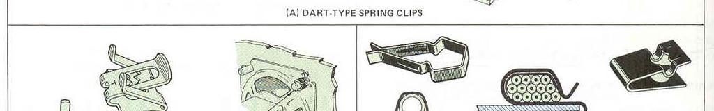
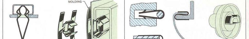
34 Springs Spring Clips Applications
35 Rivets Standard Rivets Riveting is a popular method of joining due to its simplicity, dependability d and low cost Rivets are permanent fasteners (unlike bolts and screws) A rivet is a ductile metal pin that is inserted through holes in two or more parts, and having the ends formed over to securely hold the parts Rivets can be used to join dissimilar materials of various thicknesses Can serve as fasteners, pivot shafts, spacers or inserts Can be used to fasten finished parts (after plating painting etc) If for maintenance, they have to be knocked out and clinched with new rivets once again for assembly They are neither watertight or airtight. But at higher cost they can be made to with addition of sealing compound
36 Rivets Type of Riveted Joints


37 Rivets Large Rivets Used in structural work (buildings, bridges etc) Rivets have been replaced by high strength bolts due to strength, cost and most importantly noise factor Rivet joints are either Butt or Lap joints as seen before Common types of large rivets are shown in
38 Rivets Large Rivets When shop rivets (which are put in the structure at the shop) are drawn, the diameter of the rivet head is shown on the drawings. For field rivets, the shaft diameter is used Figure shows the conventional rivet symbols adopted by the American and Canadian Institutes of Steel Construction
 Lower right quad is left")
39 Rivets Rivets for Aerospace Equipment + shows the position of the rivet Upper left quad used show part number Upper right show preformed head details Lower left to show dimpling or counter sinking (if angle not given it is 100 ) Lower right quad is left free
40 Rivets Symbolic Representation of a Line of Rivets The crosses are aligned along the axes of drawing and number of places for rives indicated. If supplemental info cannot be indicated on the drawing, use of leader lines to indicate them is fine When the rivets are aligned, identical, and equidistant, the symbols should be shown in the first and last positions, together with the total number of pitches and distance (Fig B)
41 Rivets Small Rivets Design of small rivet assemblies is influenced by two major considerations: 1. The joint itself, its strength, appearance, and configuration 2 The final riveting operation in terms of equipment capabilities 2. The final riveting operation, in terms of equipment capabilities and production sequence


 the body is sawed or")


42 Rivets Types of Small Rivets Semitubular most widely used. The depth of the hole in rivet measured along the wall does not exceed 112% of the shank dia. The hole may be extruded or drilled (straight or tapered) Full Tubular has a drilled shank with hole depth is more than 112% of the shank dia. This can punch its own hole on fabric and soft materials like plastic, eliminating i punching Bifurcated (Split) the body is sawed or punched to produce pronged shank that can punch its own hole on fabric wood or plastic Compression comprises of two members, the solid or blank rivet and a deep drilled tubular member. They form a interference fit when pressed together
43 Rivets Design Recommendations Rivet Diameters - The optimum rivet diameter is determined, not by performance requirements, but by economics-the costs of the rivet and the labor to install it. The rivet length to-diameter ratio should not exceed 6:1 Rivet Positioning - The location of the rivet in the assembled product influences both joint strength and clinching requirements. The important dimensions are edge distance and pitch distance Edge distance - Is the interval between the edge of the part and the center line of the rivet. The recommended edge distance for plastic materials, either solid or laminated, is between two and three diameters ( depending on the thickness and inherent strength of the material) Pitch distance - Unnecessarily high stress concentrations in the riveted material and buckling at adjacent empty holes can result if the pitch distance is less than three times the diameter of fthe largest rivet in the assembly (metal parts) or five times the diameter (plastic parts)
44 Rivets Design Recommendations
45 Rivets Blind Rivets Used when reverse side of the joint is not accessible. Sometimes they can be used dif other side is accessible as well Classified according to the methods to which they are set. Mainly pull mandrel, drive pin and chemically expanded
46 Rivets Design Considerations Type of Rivet Selection depends on speed of assembly, clamping capacity, available sizes, ease of removal, cost etc Joint Design Allowable tolerance of rivet length vs. assembly thickness hole clearance, joint configuration and type of loading Speed of installation fastest installation is done with power tools. Manual tools specially designed for these can be used without much training In-place costs Blind rivers have lower in-place costs than solid rivets or tapping screws Loading Blind rivet joint is usually in compression than in shear Material thickness some rivets can be set in materials as thin as 0.5mm. If one component is of compressible material (soft) extra large head diameter should be used Edge distance Average edge distance is twice the rivet dia.???
47 Rivets Design Considerations Spacing the pitch should be three times the rivet diameter Length needed for clinching action varies. Rivet manufacturers provide the grip ranges for their rivets Backup Clearance full entry is essential for proper clinch. Sufficient backup clearance must be provided to accommodate the full length of the unclinched rivet Blind Holes or Slots useful application of blind rivet is in fastening members in blind hole. In figure , B and C are stronger than A as there is no provision for formed head in A Riveted Joints lap pj joint (B) must have sufficient material beyond the hole for strength. Excessive material can cause vibration (C) Flush Joints are made by countersinking one of the section and using a rivet with countersunk head
48 Rivets Design Considerations
49 Rivets Design Considerations Weatherproof Joints rivet can be sealed by capping it A; by plugging it B; or using cap and plug C. for obtaining better sealing mastic or gasket is used between the sections Rubber Plastic and Fabric Joints some plastics such as reinforced molded fiberglass which are reasonably rigid do not pose problems for small rivets. But if the material is fabric or it is soft and flexible use methods shown in A or B. if it is not possible use a backup strip as shown in C Pivoted Joints 3 of the many ways of pivoted joints are shown Attaching a Solid Rod or Tubing when a rod is attached to other members generally the rivet completely l passes through h the rod or tubing joint as shown for structural assemblies Using pull-up by properly positioning rivets unlike parts can be pulled together using the riveting force Honeycomb Sections inserts should be employed to strengthen
50 Rivets Design Considerations
51 Welded Fasteners The most common welded fasteners are screws and nuts. Here they are grouped into Resistance welded fasteners and arc- welded studs Resistance-Welded Fasteners An externally or internally threaded metal part designed to be fused permanently in place by standard production welding equipment. Methods of resistance welding: Projection welding Spot welding
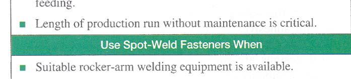
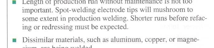
52 Welded Fasteners Resistance-Welded Fasteners Projection welding - Heat is localized through embossed or coined projections on the fastener. During the welding process, the projections coalesce with the part surface to form the weld. For best results, a press-type welder with electronic controls is usually recommended. This type of welder gives positive electrode alignment and equalized welding pressures Spot welding - The current is directed through the entire area under the electrode tip. Welding is usually performed by a spot welder. This type of welding equipment can satisfactorily weld a number of fastener designs Comparison - Spot welding costs less than projection welding. However, the projection welder is more flexible and permits far greater latitude in design

 1.")


53 Welded Fasteners Design Considerations Before fasteners can be used, three basic requirements must be met (Fig , Fig , Fig ) 1. The materials to be joined, both part and fastener, must be suitable for resistance welding 2. The parts to be welded must tbe portable enough to be carried to the welder 3. Production volume should be great enough to justify tooling costs
54 Welded Fasteners Design Considerations

55 Welded Fasteners Design Considerations
56 Welded Fasteners Arc-Welded d Studs Two basic stud welding processes; electric arc and capacitor discharge Electric Arc stud welding most widely used is semiautomatic electric arc process. To avoid burnthrough, the plate thickness should be at least one-fifth of the welding base diameter Capacitor discharge stud welding this welding process derives heat from an arc produced by a rapid discharge of stored electrical energy
57 Welded Fasteners Design Considerations In most cases the stud welding process is determined by the fastener and the base metal size Capacitor Discharge (CD) stud welding is generally used to weld smaller diameter fasteners to thin base metals Arc stud welding is generally used to weld large diameter fasteners to rougher and thicker base metals
58 Adhesive Fastening To allow greater flexibility in design, styling and materials; and cost reduction adhesive fastening is used. As with other methods these have their own advantages and disadvantages. For selection table 51 in appendix gives the application data Adhesion Versus Stress Adhesion holds materials together th and stress pulls them apart Tensile pull equally over entire joint. All adhesive contribute to bond strength Shear direction across the bond. Bond material slide over one another Peel one of the surfaces is flexible and stress is concentrated on the thin line at the edge of the bond Cleave concentrated on one edge and the other edge has zero stress
 This eliminates stress concentration caused by rivets, bolts, spot welds, and similar fastening techniques. Lighter, thinner materials can be used without sacrificing strength. 2.")
59 Adhesive Fastening Advantages Resistance to stress is the reason for using adhesive fastening Adhesives allow uniform distribution of stress over the entire bond area 1. (Fig ). 1) This eliminates stress concentration caused by rivets, bolts, spot welds, and similar fastening techniques. Lighter, thinner materials can be used without sacrificing strength. 2. Adhesives can effectively bond dissimilar materials. 3. Continuous contact between mating surfaces effectively bonds and seals against many environmental conditions. 4. Adhesives eliminate holes needed for mechanical fasteners and surface marks resulting from spot welding, brazing
60 Adhesive Fastening Limitations 1. Adhesive bonding can be slow or require critical processing. This is particularly true in mass production. Some adhesives require heat and pressure or special jigs and fixtures to establish the bond 2. Adhesives are sensitive to surface conditions. Special surface preparation may be required 3. Some adhesive solvents present hazards. Special ventilation may be required to protect employees from toxic vapors 4. Environmental conditions can reduce bond strength of some adhesives. Some do not hold well when exposed to low temperatures, high humidity, severe heat, chemicals, water
61 Adhesive Fastening Joint Design Joints need to be specifically designed All the bonded area share the load equally Joint configuration should be designed so that basic stress is primarily in shear or tensile Cleavage and peel to be minimized or eliminated


62 Adhesive Fastening Joint Design Lap Joints practical and applicable in bonding thin materials Simple lap joint can fail by cleavage and peel stress when thin materials are used Tapered single lap joint is better than simple lap Tapered edge allows bending on edges but Joggle gives more uniform stress distribution Double butt lap joint gives better load distribution than the others This type of joint requires machining which is not always possible in thinner gage materials Double scarf lap joints have better resistance to bending forces than double butt joints, again machining is required


63 Adhesive Fastening Joint Design Angle Joints give rise to peel or cleavage stress depending on the gage of metal. To reduce cleavage, typical approaches are shown Butt Joints illustrated recessed butt joints are recommended d Cylindrical Joints the T joint and overlap slip joint are typical for bonding cylindrical i l parts such as tubing, bushings and shafts


64 Adhesive Fastening Joint Design Corner Joints sheet metal assembled with adhesives using supplementary attachments. This permits joining and sealing in one operation. Typical joints are Corner Joints rigid members as in decorative fames can be adhesively bonded. End lap pjoints are simplest, they require machining. Mortise and tenon joints are excellent from design point, and require machining. Mittered joints are good if both members are hollow extrusions Stiffener Joints deflection and flutter of thin metal sheets can be minimized with adhesive bonded stiffeners
65 Adhesive Fastening Joint Design
MECHANICAL ASSEMBLY John Wiley & Sons, Inc. M. P. Groover, Fundamentals of Modern Manufacturing 2/e
 MECHANICAL ASSEMBLY Threaded Fasteners Rivets and Eyelets Assembly Methods Based on Interference Fits Other Mechanical Fastening Methods Molding Inserts and Integral Fasteners Design for Assembly Mechanical
c. Pins, bolts, and retaining rings b. Washers, locking nuts, and rivets
 62 20 HW 8: Fasteners / Force, Pressure, Density Mechanical Systems DUE Mon, 11/21/16 Start of class Check link on website for helpful fastener information Please use a scantron. Material is based primarily
Fasteners. Metal Fasteners, Joining, and Adhesives. Bolts. Metal Fasteners, Joining, and Adhesives
 Metal Fasteners, Joining, and Adhesives Fasteners Metal assemblies are often held together with fasteners, hardware devices that mechanically join or affix two or more objects together. Assembling with
CIRRUS AIRPLANE MAINTENANCE MANUAL
 FASTENER AND HARDWARE GENERAL REQUIREMENTS 1. DESCRIPTION This section contains general requirements for common hardware installation. Covered are selection and installation of cotter pins, installation
Permanent fasteners: Riveted joints Welded joints Detachable joints: Threaded fasteners screws, bolts and nuts, studs. Cotter joints Knuckle joints
 Instructional Objectives At the end of this lesson, the students should have the knowledge of Fasteners and their types: permanent and detachable fasteners. Different types of pin joints. Different types
1/2/2016. Lecture Slides. Screws, Fasteners, and the Design of Nonpermanent Joints. Reasons for Non-permanent Fasteners
 Lecture Slides Screws, Fasteners, and the Design of Nonpermanent Joints Reasons for Non-permanent Fasteners Field assembly Disassembly Maintenance Adjustment 1 Introduction There are two distinct uses
ME 114 Computer Aided Engineering Drawing - II
 ME 114 Computer Aided Engineering Drawing - II Nonthreaded Fasteners & Springs Asst.Prof.Dr.Turgut AKYÜREK Çankaya University, Ankara Nonthreaded Fasteners Mechanical devices used to prevent motion between
Chapter 7. Fasteners
 Chapter 7 Fasteners LEARNING OBJECTIVES After studying this chapter, students will be able to: Identify several types of fasteners. Explain why inch-based fasteners are not interchangeable with metric-based
RIVETING Rivet types Solid rivets Solid rivets are used less and less. They have been replaced in many cases by welding or bonding.
 10.1 Rivet types 10.1.1 Solid rivets Solid rivets are used less and less. They have been replaced in many cases by welding or bonding. Because of the large countersinking angle of 140 flat countersunk
POP BLIND RIVET NUTS.
 POP BLIND RIVET NUTS www.emhart.com POP NUT Blind Rivet Nuts Introduction POP NUT brand blind rivet nuts are internally threaded rivets that can be installed into sheet-metal, tubing, extrusions, plastics
Mobile Weapons Storage System Specifications
 Mobile Weapons Storage System Specifications Whatever your weapon storage needs, Hi-Density s customized Weapons Storage System will be designed to fit your unique specifications. We recognize that security
Brazing Braze Welding
 1 2 3 4 Brazing Filler metals typically melt above 450 o C (840 o F); Below MP of host metals. Term brazing derived from brass, to harden Process originated 3000-2000 B.C. Typically, a filler (braze) metal
SECTION 7. SAFETYING
 9/8/98 AC 43.13-1B SECTION 7. SAFETYING 7-122. GENERAL. The word safetying is a term universally used in the aircraft industry. Briefly, safetying is defined as: Securing by various means any nut, bolt,
Clips, an Alternative Fastener System
 395 Clips, an Alternative Fastener System by Thomas Doppke There are times when a screw or threaded product just won t fit the attachment requirements. Not enough space, backside clearance, not reachable
1. Enumerate the most commonly used engineering materials and state some important properties and their engineering applications.
 Code No: R05310305 Set No. 1 III B.Tech I Semester Regular Examinations, November 2008 DESIGN OF MACHINE MEMBERS-I ( Common to Mechanical Engineering and Production Engineering) Time: 3 hours Max Marks:
Operating Instructions For Lockformer Button Punch Flanger
 Capacity: 20 to 28 Gauge Galvanize Operating Instructions For Lockformer Button Punch Flanger To satisfactorily form the 90º button punch flange on light gauge materials, it was necessary to form the metal
UNIT 9b: SCREW FASTENERS Introduction Functions Screw Features Elements Terms of a Thread Profile
 UNIT 9b: SCREW FASTENERS Introduction A mechanical screw is a cylinder or cone that has a helical ridge called a thread. A helix has one or more turns, so a screw can have several turns. If the helix is
Mechanical Drawing. Fig 5-1
 College of Engineering 1 Mechanical Drawing Mechanical Engineering Department Mechanical Drawing Lecture 5 Keys and keyways 5-1 Introduction A key, Fig. 5.1, is usually made from steel and is inserted
DESIGN OF MACHINE MEMBERS-I
 Code No: R31035 R10 Set No: 1 JNT University Kakinada III B.Tech. I Semester Regular/Supplementary Examinations, Dec - 2014/Jan -2015 DESIGN OF MACHINE MEMBERS-I (Mechanical Engineering) Time: 3 Hours
Air Cooled Engine Technology. Roth 9 th Ch 3 Fasteners & Sealing Pages 45 65
 Roth 9 th Ch 3 Fasteners & Sealing Pages 45 65 1. Engine & equipment can be common or can be designed to perform specific functions. Fasteners Options Features 2. The of a fastener is actually an inclined
LANDMARK UNIVERSITY, OMU-ARAN
 LANDMARK UNIVERSITY, OMU-ARAN LECTURE NOTE: DRILLING. COLLEGE: COLLEGE OF SCIENCE AND ENGINEERING DEPARTMENT: MECHANICAL ENGINEERING PROGRAMME: MECHANICAL ENGINEERING ENGR. ALIYU, S.J Course code: MCE
Unit4 31. UnitS 39. Unit 6 47
 Preface..................... xi About the Author......... xiii Acknowledgments... xiv Unit 1 1 Bases for Interpreting Drawings........ I Visible Lines............. 3 Lettering on Drawings... 3 Sketching...
Replacement of Pitch Link Retainer and Service Improvement of the Pitch Control System. Effectivity: Helicopters manufactured prior to January, 1981
 Page 1 of 12 Date: December 2, 1981 Subject: Models: Replacement of Pitch Link Retainer and Service Improvement of the Pitch Control System F-28C and 280C Effectivity: Helicopters manufactured prior to
Chapter Tests and Problems
 Chapter Tests and Problems Chapter 11 Fasteners and Springs Test INSTRUCTIONS Answer the questions with short, complete statements or drawings as needed. QUESTIONS Define the screw thread terms given in
Machine Your Fishing Reel
 Machine Your Fishing Reel You will be well prepared for the coming season if you start on this smooth-running job now. IF you're an enthusiastic fisherman and have a lathe in your workshop, we'll say no
METAL FABRICATION MECHANICAL
 METAL FABRICATION MECHANICAL Machine Screws Machine screws have a parallel thread and need a threaded hole to screw into. They come in a wide variety of materials and sizes and are used for semi-permanent
joining materials - wood
 UNIT D E S I G N A N D M A N U F A C T U R E : C O U R S E M A T E R I A L Wood joints joining materials - wood The majority of joints used in woodcraft have been designed specifically to attain the maximum
METRIC FASTENERS 1520 METRIC FASTENERS
 1520 METRIC FASTENERS METRIC FASTENERS A number of American National Standards covering metric bolts, screws, nuts, and washers have been established in cooperation with the Department of Defense in such
CH # 8. Two rectangular metal pieces, the aim is to join them
 CH # 8 Screws, Fasteners, and the Design of Non-permanent Joints Department of Mechanical Engineering King Saud University Two rectangular metal pieces, the aim is to join them How this can be done? Function
Various other types of drilling machines are available for specialized jobs. These may be portable, bench type, multiple spindle, gang, multiple
 Drilling The process of making holes is known as drilling and generally drilling machines are used to produce the holes. Drilling is an extensively used process by which blind or though holes are originated
General Four-Way Operation, Maintenance & Service Manual
 General Four-Way Operation, Maintenance & Service Manual SCOPE Included in the following pages you will find assembly drawings, exploded views, parts lists, assembly tips, operational descriptions and
REPAIR INSTRUCTIONS. Cat. No Cat. No MILWAUKEE ELECTRIC TOOL CORPORATION. SDS Max Demolition Hammer. SDS Max Rotary Hammer
 Cat. No. 9-0 SDS Max Demolition Hammer Cat. No. -0 SDS Max Rotary Hammer MILWAUKEE ELECTRIC TOOL CORPORATION W. LISBON ROAD BROOKFIELD, WISCONSIN 00-0 8-9-0 d 000 8-9-0 d Special Tools Require Forcing
MATERIAL COMBINATION NUMBER 2: Corrosive environment requiring harder, wear-resistant seating faces and resistance to dezincification.
 Cast Iron Slide Gates Spec Sheet General The contractor shall furnish and install the following cast iron slide gate assemblies as listed on the Gate Schedule and detailed on the manufacturer s drawings.
Tuf-Lite III Fans 5000K Series Hub
 Tuf-Lite III Fans 5000K Series Hub INSTALLATION MANUAL Hudson Tuf-Lite III fan blades Adjustable Pitch Fan Assembly 20 thru 30 Diameter Hudson Tuf-Lite III fan blades are of single piece fiberglass reinforced
Tuf-Lite and Tuf-Lite II Fans 4000 Series Hub
 Tuf-Lite and Tuf-Lite II Fans 4000 Series Hub INSTALLATION MANUAL Hudson Tuf-Lite and Tuf-Lite II fan blades Adjustable Pitch Fan Assembly 15 thru 20 Diameter Hudson Tuf-Lite (black) fan blades are made
Student, Department of Mechanical Engineering, Knowledge Institute of Technology, Salem, Tamilnadu (1,3)
") International Journal of Scientific & Engineering Research, Volume 7, Issue 5, May-2016 11 Combined Drilling and Tapping Machine by using Cone Mechanism N.VENKATESH 1, G.THULASIMANI 2, S.NAVEENKUMAR 3,
International Journal of Scientific & Engineering Research, Volume 7, Issue 5, May-2016 11 Combined Drilling and Tapping Machine by using Cone Mechanism N.VENKATESH 1, G.THULASIMANI 2, S.NAVEENKUMAR 3,
HIGH ENERGY RATE FORMING PROCESSES
 HIGH ENERGY RATE FORMING PROCESSES In these forming processes large amount of energy is applied for a very short interval of time. Many metals tend to deform more readily under extra fast application of
Tuf-Lite III Fans K Hi Temp 3000KHT Series Hub
 Tuf-Lite III Fans K Hi Temp 3000KHT Series Hub INSTALLATION MANUAL Adjustable Pitch Fan Assembly 11 thru 15 Diameter Hudson Tuf-Lite III fan blades Hudson Tuf-Lite III Hi Temp (Red) fan blades are of single
Tuf-Lite II Fans H Hi Temp 3000HT Series Hub
 Tuf-Lite II Fans H Hi Temp 3000HT Series Hub INSTALLATION MANUAL Hudson Tuf-Lite II Hi Temp Fan Blades Adjustable Pitch Fan Assembly 5 through 14 Diameter Hudson Tuf-Lite II Hi Temp fan blades (Red) are
Design of Jigs, Fixtures, Press Tools and Moulds UNIT - 1 LOCATING AND CLAMPING PRINCIPLES
 Design of Jigs, Fixtures, Press Tools and Moulds UNIT - 1 LOCATING AND CLAMPING PRINCIPLES 1. Define the term Tool design. Tool design is the process of designing and developing the tools, methods, and
Introduction to Manufacturing Processes
 Introduction to Manufacturing Processes Products and Manufacturing Product Creation Cycle Design Material Selection Process Selection Manufacture Inspection Feedback Typical product cost breakdown Manufacturing
UNIT 4: (iii) Illustrate the general kinematic system of drilling machine and explain its working principle
 Illustrate the general kinematic system of drilling machine and explain its working principle") UNIT 4: Drilling machines: Classification, constructional features, drilling & related operations, types of drill & drill bit nomenclature, drill materials. Instructional Objectives At the end of this
UNIT 4: Drilling machines: Classification, constructional features, drilling & related operations, types of drill & drill bit nomenclature, drill materials. Instructional Objectives At the end of this
Tuf-Lite and Tuf-Lite II Fans 4000 Series Hub
 Tuf-Lite and Tuf-Lite II Fans 4000 Series Hub INSTALLATION MANUAL Hudson Tuf-Lite and Tuf-Lite II fan blades Adjustable Pitch Fan Assembly 15 thru 20 Diameter Hudson Tuf-Lite (black) fan blades are made
Tuf-Lite III Fans 5000K Series Hub
 Tuf-Lite III Fans 5000K Series Hub INSTALLATION MANUAL Hudson Tuf-Lite III fan blades Adjustable Pitch Fan Assembly 20 thru 30 Diameter Hudson Tuf-Lite III fan blades are of single piece fiberglass reinforced
INSTALLATION INSTRUCTIONS FOR INSTALLING T-SERIES EXTRA HEAVY DUTY LEVER LOCKSET
 HIGH EDGE 2 1/4"(57mm) 03079400070 INSTALLATION INSTRUCTIONS FOR INSTALLING T-SERIES EXTRA HEAVY DUTY LEVER LOCKSET IMPORTANT: THIS LOCK IS NON-HANDED. LOCK IS FACTORY PACKED PREADJUSTED FOR 1³ ₄" (45mm)
Interactive Monitor Arm
 Interactive Monitor Arm Tools Required -5mm Allen wrench -Phillips screwdriver -Plastic mallet There are two ways to attach a Monitor Arm to a Full Frame; with a Beam, or with a Post Mount. Both methods
Sheet Metal Tools. by:prem Mahendranathan
 Sheet Metal Tools by: SHEET METAL TOOL KIT SHEET METAL TOOLS Rivet Gun 3/32, 1/8, 5/32, 3/16",Cupped Set Mini Bucking Bar Footed Heel-Toe Bucking Bar Air Tool Oil Mechanics Tool Bag High-Speed Air Drill
AndyMark DART 12.
 AndyMark DART 12 Part Number Description QTY These Parts Are Pre-Assembled by AndyMark am-0031 Bearing, 3/16"ID (R3) 1 am-0209 Bearing, 3/8"ID 1614ZZ 2 am-1028 Screw, #10-32x3/8 Pan Head Philips 8 am-1121
Reamer Basics. Fixed Reamers The reamer size is fixed and any size reduction due to wear or sharpening cannot be reclaimed
 1 Reamer Basics Reamers are available in a variety of types, materials, flute styles and sizes The typical reamer is a rotary cutting tools designed to machine a previously formed hole to an exact diameter
Tuf-Lite III Fans 3000K Series Hub
 Tuf-Lite III Fans 3000K Series Hub INSTALLATION MANUAL Adjustable Pitch Fan Assembly 11 thru 15 Diameter Hudson Tuf-Lite III fan blades Hudson Tuf-Lite III fan blades are of single piece fiberglass reinforced
Hours / 100 Marks Seat No.
 17610 15116 4 Hours / 100 Seat No. Instructions (1) All Questions are Compulsory. (2) Answer each next main Question on a new page. (3) Illustrate your answers with neat sketches wherever necessary. (4)
Screws. Introduction. 1. Nuts, bolts and screws used to clamp things together. Screws are used for two purposes:
 Screws Introduction Screws are used for two purposes: 1. To clamp things together. 2. To control motion. 1. Nuts, bolts and screws used to clamp things together. Nuts, bolts and screws that are used for
Tuf-Lite II Fans 3000H Series Hub
 Tuf-Lite II Fans 3000H Series Hub INSTALLATION MANUAL Adjustable Pitch Fan Assembly 5 through 14 Diameter Hudson Tuf-Lite II Fan Blades Hudson Tuf-Lite II (white, prev. Blue**) are made from fiberglass
STRENGTH Aligned teeth provide superior gripping power over standard vertical teeth. STRENGTH Diamond serrated jaws provide a firm grip
 STRENGTH Aligned teeth provide superior gripping power over standard vertical teeth STRENGTH Diamond serrated jaws provide a firm grip PLIERS AND SNIPS Locking Pliers Slip Joint Pliers Electrician s Pliers
Exploration of a Student Project in a Materials Processing Course
 Paper ID #8093 Exploration of a Student Project in a Materials Processing Course Prof. Somnath Chattopadhyay, Georgia Southern University c American Society for Engineering Education, 2013 EXPLORATION
Tuf-Lite II Fans 3000H Series Hub
 Tuf-Lite II Fans 3000H Series Hub INSTALLATION MANUAL Adjustable Pitch Fan Assembly 5 through 14 Diameter Hudson Tuf-Lite II Fan Blades Hudson Tuf-Lite II (white, prev. blue**) fan blades are made from
SERIES I MILLING MACHINES
 INSTALLATION, OPERATION, MAINTENANCE, AND PARTS LIST SERIES I MILLING MACHINES TP5260 Revised: August 29, 2005 Manual No. M-450 Litho in U.S.A. Part No. M -0009500-0450 June, 2003 MAINTENANCE PROCEDURES
25000 Series Lo-T TM Butterfly Control Valve Instructions
 November 2001 25000 Series Lo-T TM Butterfly Control Valve Instructions Instruction No. 25.1:IM PRELIMINARY STEPS Before installation, note the flow direction arrow on the valve body. The flow should enter
TECH SHEET PEM - REF / TESTING CLINCH PERFORMANCE. SUBJECT: Testing clinch performance of self-clinching fasteners.
 PEM - REF / TESTING CLINCH PERFORMANCE SUBJECT: Testing clinch performance of self-clinching fasteners. A self-clinching fastener s performance can be divided into two major types. The first is self-clinching
Reversing Gear. Shay Reversing Gear
 Shay Nelson Riedel Nelson@NelsonsLocomotive.com Initial: 9/23/03 Last Revised: 06/05/2004 The reversing gear is another one of those pieces I've been putting off. The reason for the postponement was that
Tuf-Lite II Fans 3000HC Series Hub
 Tuf-Lite II Fans 3000HC Series Hub INSTALLATION MANUAL Hudson Tuf-Lite II fan blades Adjustable Pitch Fan Assembly 8 through 10 Diameter Hudson Tuf-Lite II (White) are made from fiberglass reinforced vinyl-ester
Unit IV Drawing of rods, wires and tubes
 Introduction Unit IV Drawing of rods, wires and tubes Drawing is a process in which the material is pulled through a die by means of a tensile force. Usually the constant cross section is circular (bar,
Model No: TC10. Parts Information: Tyre Changer - Automatic
 Page 1 of 11 1 TC10.01 BODY 2 TC10.02 COLUMN 3 TC10.03 HORIZONTAL ARM ASS'Y 4 TC10.04 WASHER 5 TC10.05 RUBBER FOOT 6 TC10.06 COVER 7 TC10.07 SCREW M14x42 8 TC10.08 PRESS COVER 9 TC10.09 STOP-UP 10 TC10.10
RH-412 STEEL DOORS INSTALLATION INSTRUCTIONS
 RH-412 STEEL DOORS INSTALLATION INSTRUCTIONS By following the steps outlined below, the assembly, installation and adjustment of the steel doors, will be a simple process. Let s start with the Driver Side.
Corso di Studi di Fabbricazione
 Corso di Studi di Fabbricazione 3a Richiami dei processi tecnologici di trasformazione FUNDAMENTAL OF METAL FORMING 1 METAL FORMING Large group of manufacturing processes in which plastic deformation is
ROOP LAL Unit-6 Lathe (Turning) Mechanical Engineering Department
 Mechanical Engineering Department") Notes: Lathe (Turning) Basic Mechanical Engineering (Part B) 1 Introduction: In previous Lecture 2, we have seen that with the help of forging and casting processes, we can manufacture machine parts of
Notes: Lathe (Turning) Basic Mechanical Engineering (Part B) 1 Introduction: In previous Lecture 2, we have seen that with the help of forging and casting processes, we can manufacture machine parts of
bcprecision Devices, Inc. HYDRAULIC ARBORS AND CHUCKS
 UNEQUALED WORK HOLDING ACCURACY for: grinding; balancing; inspection; boring; facing; reaming; drilling; turning; shaving; hobbing and honing b SQUARENESS r CONCENTRICITY f PARALLELISM e ROUNDNESS v ALIGNMENT
TAPTITE 2000 Fasteners
 TAPTITE 2000 Fasteners Unique Design Increases Performance TAPTITE 2000 fasteners are designed to provide the benefits of previous TAPTITE fastener products with an innovative new thread design the Radius
MSR/MSB Mechanical Setting Tool
 Tech Unit No: 0620000004 Revision: B Approved By: Quality Engineer Date: 2014-12-16 MSR/MSB Mechanical Setting Tool FEATURES: Special designed Bow Spring provides positive control and allows one size Mechanical
Manufacturing Processes (continued)
") Manufacturing (continued) Machining Some other processes Material compatibilities Process (shape) capabilities Manufacturing costs Correct pg 142, question 34i should read Fig 6.18 question 34j should
Manufacturing (continued) Machining Some other processes Material compatibilities Process (shape) capabilities Manufacturing costs Correct pg 142, question 34i should read Fig 6.18 question 34j should
1. Turn off or disconnect power to unit (machine). 2. Push IN the release bar on the quick change base plate. Locking latch will pivot downward.
. 2. Push IN the release bar on the quick change base plate. Locking latch will pivot downward.") Figure 1 Miniature Quick Change Applicators, of the end feed type, are designed to crimp end feed strip terminals to prestripped wires. Each applicator is set up to accept the strip form of certain specific
Figure 1 Miniature Quick Change Applicators, of the end feed type, are designed to crimp end feed strip terminals to prestripped wires. Each applicator is set up to accept the strip form of certain specific
Fig. 2 DORMA-Glas Stand/Issue 02/03 Seite/Page 1/7
 FSW Installation instructions Track rail 75 x 72 mm 1. Ceiling substructure and installation of the track rail (Fig. 1): The track rail must be bolted over its entire length (including the stacking track
MANUAL PLASTIC STRAPPING TOOL MODEL P404
 OPERATION MANUAL / SPARE PARTS LIST MANUAL PLASTIC STRAPPING TOOL MODEL P404 43.0404.02 43040402.en/MAS/ 12.05 INDEX PAGE 1 SAFETY INSTRUCTIONS 2 2 TECHNICAL DATA 3 3 OPERATION ELEMENTS 4 4 ADJUSTMENT
White Paper Feather Keys: The forgotten and ignored drive component
 White Paper Feather Keys: The forgotten and ignored drive component Copyright 2009 by Rino Mechanical See us at www.rinomechanical.com Mechanical Components Inc. 216 North Main Street, Freeport, NY 11520
RASCH / SAFIX. Release Numbering at RASCH / SAFIX. Structure of families with additional functions. Summary of the forms
 RASCH / SAFIX Release 2008 Automatic Search System of Fastenings RECHNERUNTERSTÜTZTES AUSWAHLSYSTEM FÜR SCHNELLEFESTIGER SYSTÈME AUTOMATIQUE DE RECHERCHE DE FIXATIONS Numbering at RASCH / SAFIX Structure
INSTALLATION INSTRUCTIONS RH 412 STEEL DOORS
 By following the steps outlined below, the assembly, installation and adjustment of the steel doors, will be a simple process. Let s start with the Driver Side. Note: Having the hood open makes the job
Interference Fits Interference Fits Reference Lecture 15 Notes
 Interference Fits Interference Fits Hole is undersized and part is heated to allow it to slide over shaft. Compressive interface pressure develops when part cools. Reference Lecture 15 Notes. Keys and
Lathe. A Lathe. Photo by Curt Newton
 Lathe Photo by Curt Newton A Lathe Labeled Photograph Description Choosing a Cutting Tool Installing a Cutting Tool Positioning the Tool Feed, Speed, and Depth of Cut Turning Facing Parting Drilling Boring
Assembly Instructions 10 X 10 Aluminum Frame Building
 Assembly Instructions 10 X 10 Aluminum Frame Building 27 97 9 8 47 36 74 52 10 10 X 10 Square Building W/ Dome Includes: The Steel Entry Door with a Dead Bolt Lock assembly and Aluminum Door Frame. Metal
Fastener Type Chart. Fastener Categories. Sheet Metal Screws Fully threaded screws with a point for use in sheet metal. Abbreviated SMS.
 Fastener Categories Wood Screws Machine Screws Thread Cutting Machine Screws Screws with a smooth shank and tapered point for use in wood. Abbreviated WS. Screws with threads for use with a nut or tapped
STAR TOOL SUPPLY / GRAND TOOL SUPPLY
 Made of hardened and tempered tool steel with ground points. es have knurled grip. Set consists of 1 each of 5 punches in plastic pouch. Point Size Length 1/16 3 3040004 5/64 4 3040005 3/32 4 3040006 9/64
C-Clamps and Lifting Eyes (Eye Bolts)
") 0-C-Clamps & Lifting Eyes-R 2/21/08 9:42 PM Page 1 C-Clamps A B C Armstrong C-Clamps When your requirements call for clamps, specify Armstrong the most accepted name in the business. When you see Armstrong
0-C-Clamps & Lifting Eyes-R 2/21/08 9:42 PM Page 1 C-Clamps A B C Armstrong C-Clamps When your requirements call for clamps, specify Armstrong the most accepted name in the business. When you see Armstrong
FITTING INTRODUCTION:
 FITTING INTRODUCTION: Machine tools are capable of producing work at a faster rate, but there are occasions when components are processed at the bench. Sometimes it becomes necessary to replace or repair
ASSIGNMENT 4. Textbook Assignment: The point, edge, face, heel, and tang are the five parts of which of the following tools?
 ASSIGNMENT 4 Textbook Assignment: "Files," "Grinders and Sharpening Stones," "Scrapers," "Awls," "Bolt and Cable Cutters," "Glass Cutters," "Knives,' 'Pipe Cutting and Threading Tools," "Tube Cutting and
HEAVY DUTY GASKET CUTTER
 HEAVY DUTY GASKET CUTTER GUIDE TO PERFECT GASKETS CUTTING GASKETS 1 TO 13 IN DIAMETER: 1. Lay out gasket outer diameter (OD), inner diameter (ID) and bolt holes on template or gasket material. See section
THE GATE COACHAll Rights Reserved 28, Jia Sarai N.Delhi ,-9998
 1 P a g e 1 DESIGN AGAINST STATIC AND FLUCTUATING LOADS 2 SHAFT, KEYS AND COUPLINGS CONTENTS Introduction 6 Factor of safety 6 Stress concentration 7 Stress concentration factors 8 Reduction of stress
Hinge Mortising Jig. One of the make it or break it parts of building a. 6 ShopNotes No. 74
 Hinge Mortising Jig A Mortise for a Hinge. Quick, clean, and accurate that s the only way to describe the mortise you get with a trim router and this hinge mortising jig. One of the make it or break it
System 3000 specifications
 System 3000 specifications Scope: Materials: Type of Bookstack: This specification covers delivery and installation of steel library shelving of the bracket type. Height, depth and accessories shall be
SERVICE PARTS LIST PAGE 1 OF 6 BASE ASSEMBLY SPECIFY CATALOG NO. AND SERIAL NO. WHEN ORDERING PARTS 12" SLIDING COMPOUND MITER SAW
 PAGE 1 OF 6 BASE ASSEMBLY 00 0 CATALOG NO. EXAMPLE: SPECIFY CATALOG NO. AND NO. WHEN ORDERING PARTS 6955-20 1 02-80-0050 Thrust Bearing (1) 2 05-80-0510 M5 x 12mm Flat Head T-20 Screw (5) 3 05-81-0135
MSR/MSB Mechanical Setting Tool
 Tech Unit No: 0620000004 Revision: C Approved By: Quality Engineer Date: 201-1-9 MSR/MSB Mechanical Setting Tool FEATURES: Special designed Bow Spring provides positive control and allows one size Mechanical
Typical Parts Made with These Processes
 Turning Typical Parts Made with These Processes Machine Components Engine Blocks and Heads Parts with Complex Shapes Parts with Close Tolerances Externally and Internally Threaded Parts Products and Parts
Section 914. JOINT AND WATERPROOFING MATERIALS
 914.01 Section 914. JOINT AND WATERPROOFING MATERIALS 914.01. General Requirements. Joint and waterproofing material for use in concrete construction must meet the requirements of this section. 914.02.
RIVETS AND THREADED INSERTS
 RIVETS AND THREADED INSERTS Tri-Clamp, Multi-Grip, Dome Head and Stainless Steel Rivets Multi-Grip Rivets Adapt to All Material Types and Thicknesses Threaded Inserts Install Threads Into Blind Areas and
ACCESSORIES CATALOG. SKODA LIVE CENTERS BORING AND FACING HEADS
 ACCESSORIES CATALOG BORING AND FACING HEADS SKODA LIVE CENTERS www.sowatool.com SKODA LIVE CENTERS Skoda Heavy Duty Live Centers - CSN 4334/CSN 4334M Features The rotating spindle is extended right through
Suggested Methods of Mounting Free-Flex Pivots
 Suggested Methods of Mounting Free-Flex Pivots For most applications, Riverhawk recommends orientation of the pivot to operate with a V c load condition. V c load is defined as a pure radial load located
PARTS LIST. Clarke CL500M 6 spd. Metal Lathe Part Number: HT HT HT
 PARTS LIST Clarke CL500M 6 spd. Metal Lathe Part Number: - 7610300 Quantity Description Part Number 1 Countersunk Hd, screw m5x14 HT3000101 1 Retaining Ring, 28 HT3000102 1 Bevel Gear HT3000103 1 Washer
Wire and tube Drawing
 Wire and tube Drawing Drawing is an operation in which the cross-section of solid rod, wire or tubing is reduced or changed in shape by pulling it through a die. The principle of this procedure consist
The Canadian Tire Paint Roller A Technical Description
 A Technical Description Eric Morlang Table of Contents 1. General Description of the Paint Roller... 3 2. Part-By-Part Description of the Paint Roller... 4 2.1 Body... 4 2.1.1 Handle... 4 2.1.2 Wire...
Motorized M3 AX7200 Rotary-Style Gasket Cutter Operating Instructions
 Motorized M3 AX7200 Rotary-Style Gasket Cutter Operating Instructions INTRODUCTION Congratulations! You are the owner of the finest rotary-style gasket cutter in the world. Originally developed and patented
Question Bank Technical Drawing Metal
 Question Bank Technical Drawing Metal Table of Contents Question Bank Technical Drawing Metal...1 ASSEMBLY DRAWINGS & DETAILS...1 READING OF DRAWINGS...38 VIEWS...61 MACHINE ELEMENTS...87 i ii Question