The Nanosolar Utility Panel An Overview of the Solar Panel and its Advantages. May 2010
|
|
|
- Phillip Stephens
- 5 years ago
- Views:
Transcription

1 May 2010
 of")
2 The Nanosolar Utility Panel 1 Designed for Utility-Scale Performance The Nanosolar Utility Panel is specifically designed for utility-scale systems. Engineered to reduce totalsystem cost, the product is electrically and mechanically optimized for utility-scale solar power systems: Electrically capable of supporting more than 6 Amps (A) of current, the Nanosolar Utility Panel is one of the industry s highest-current thin-film panels. It is also the industry s first photovoltaic panel certified by TÜV for a system voltage of 1,500V. High current and system voltage enable longer panel arrays, resulting in a host of cost savings during installation. Mechanically, the dual-tempered glass/glass package used for the Nanosolar Utility Panel is stronger than conventional thin-film-on-glass panels, delivering almost twice the mounting span, and requiring less mounting hardware. The Nanosolar Utility Panel meets and exceeds all tests required by applicable IEC and UL standards, including separate certification of the Nanosolar Edge Connector. State-of-the-art robotic automation is used to assemble the Nanosolar Utility Panel in a factory near Berlin, Germany, delivering the highest degree of quality. 2 Product Features and Benefits Based on an industry proven glass/glass laminate package engineered for more than 25 years of reliability, the panel s unique features and benefits include the following: High-Power Panel for Faster Deployment At power ratings ranging from 160W to 220W, the Nanosolar Utility Panel has up to three times more power per panel than conventional thin-film panels. More power per panel simplifies industrial-scale deployment. Tests have shown a significant reduction in installation labor time relative to conventional thin panels (see Reduced BoS Cost: Mounting and Cabling Labor, page 4). Rugged, Hermetically Sealed Package for Maximum Reliability A rugged glass/glass package with encapsulation based on a hermetic edge seal is used to ensure maximum durability and to eliminate moisture ingress. Nanosolar encapsulant technology is engineered to exceed the sealing performance of conventional thinpanel products, providing an additional safety buffer for 25 year reliability. Mechanically Strong Package for Wide-Span Mounting Conventional thin-film-on-glass panel manufacturers deposit the solar-cell stack of thin films directly onto a glass pane, which also offers protection from the outside environment. Nanosolar produces individual foil cells, sorts them into electrically matched circuits, and assembles these circuits into a panel. By utilizing sorted-cell assembly, Nanosolar gains a panel assembly yield advantage and broad flexibility in terms of panel size, form factor and package style. The Nanosolar Utility Panel uses tempered glass on both the front and back of its glass/glass package. Note that the use of two tempered glass panes is not possible for producers of thin-film-on-glass panels, because high-temperature cell production process steps lead to de-tempering. The Nanosolar Utility Panel - May
3 The use of dually tempered glass panes with foil cells in between creates a package of significant mechanical strength. Tempered glass has a strength of 120MPa, three times stronger than regular glass. The resulting system benefit is that it enables wide-span mounting, which reduces the cost of mounting materials and labor. High-Current, High-System-Voltage Design for Utility-Scale Panel Arrays With capacity to generate currents of 6-7 Amps, the Nanosolar Utility Panel is one of the highest-current thin-film panels in the industry, and the first photovoltaic panel certified by TÜV for a system voltage of 1500V. Once a string of panels reaches the system voltage, a DC cable home run is required to carry the power to an inverter. If the panel s current is low, as is the case with many thin-film-on-glass products, the system voltage is reached with fewer panels, requiring more DC cabling home runs for the same amount of installed power. The electrical characteristics of a panel combined with its physical length determine the panel string length, the maximum length per row of panels that can be wired in series before a home run is required. Panel string length = System voltage Open-circuit voltage* x Panel length** *Open-circuit voltage at low temperature. **Panel length in mounting orientation. The Nanosolar Utility Panel supports a panel string length of 64m, several times longer than leading thinfilm panels currently in use for large-scale ground installations. In utility-scale systems, where distances are vast, a longer panel string substantially reduces cabling requirements. (see Reduced BoS Cost: Cabling Length and Labor for further detail) Nanosolar Edge Connector for Fast, Minimal-Resistive-Loss Interconnection Nanosolar has developed a new form of cabling connection for the Nanosolar Utility Panel. A component separately tested and certified by TÜV according to the applicable connector standards, the Nanosolar Edge Connector is designed to reduce cabling labor, save material cost, and minimize resistive losses for utility-scale system deployments. Figure 1: The Nanosolar Utility Panel mounted in landscape mode. There are two Nanosolar edge connectors per panel. A short cable connects each panel from left to right. The Nanosolar Edge Connector is designed to enable high system voltage and to simplify electrical connection. Field tests performed by an independent third party have shown a reduction in labor time for panel interconnection relative to conventional thin film panels. The Nanosolar Utility Panel - May
4 3 Reducing Balance-of-System Cost Compared to conventional thin-film panels, these Nanosolar Utility Panel features and benefits have the following cost advantages: Nanosolar Conventional Thin Film Nanosolar Advantage Power (W) x More Power per Layup Step Current (A) 6 1 Longer Panel String System Voltage (V) Longer Panel String Panel Size (m 2 ) Less Mounting Time Panel String Length (m) Fewer Inverter Home Runs Mounting Span (m) Less Mounting Material Connectors Edge Standard Significant Savings in Cabling Material Table 1: The Nanosolar Utility Panel stretches performance characteristics along several key dimensions relative to conventional thin panels. These technology attributes drive BoS and deployment cost efficiency in several key ways. The design of the Nanosolar Utility Panel enables BoS cost savings on mounting labor, cabling labor, mounting materials, and cabling materials, as further described below. Reduced BoS Cost: Mounting and Cabling Labor Solar panel installations require two types of cabling: Series interconnection of panel strings DC cable home runs to the inverter The high current, high system voltage design of the Nanosolar Utility Panel simplifies both types of cabling. Simplified cable harnesses can be utilized which reduce the number of series interconnections. In addition, fewer DC cable home runs are required, resulting in a significant savings in labor time. DC cables are typically placed in trenches, which must be dug and covered. In addition, each cable requires connections to both the panel string and the inverter. A third party performed time-clocked tests in a field in Germany, where trained teams of installers mounted 18 square meters (1800W) each of conventional thin film panels and Nanosolar panels. The Nanosolar Utility Panel required 30% less mounting time and 85% less cabling time. The Nanosolar Utility Panel - May
5 Nanosolar panels Conventional thin-film panels Figure 3: Panel size drives balance-of-system cost savings on mounting labor and panel-to-panel cabling. Balance of System Cost: DC Cabling Nanosolar First Conventional Solar Thin Film 138*96 = 13,248 panels 230*160 = 36,800 panels = 4*12 panels = 10*10 panels 8*12 = 96 panels 16*10 = 160 panels 23*4 = 138 rows 23*10 = 230 rows Figure 4: Two example 2.66MW systems, one designed with the Nanosolar Utility Panel, and one employing a conventional thin film panel. Field dimensions are 300m x 230m. DC Cabling is represented by orange lines. Panel string length is 64m for Nanosolar and 12m for conventional thin film. The system designed with conventional thin film panels requires 17 home runs while the Nanosolar Utility Panel system design requires only 4 home runs. The Nanosolar Utility Panel installation utilizes 73% less DC cabling than the conventional thin film installation. The Nanosolar Utility Panel - May

6 Reduced BoS Cost: Mounting and Cabling Materials The wide-span mounting capability of the Nanosolar Utility Panel reduces BoS cost on mounting materials as illustrated in the following figure. By virtue of having a larger spanning distance than conventional thin film panels, 40% fewer Aluminum or steel rails are needed for mounting, reducing a substantial fraction of materials cost. Figure 2: Wide-span mounting drives BoS cost savings on mounting materials. The arrow above indicates the freespan distance that a panel must sustain mechanically (with snow loads up to 5400Pa) when installed in a typical railmount configuration. The larger the mounting span, the fewer rails are necessary. The Nanosolar Utility Panel supports a higher current (6A) and a higher system voltage (1500V) than industry-leading thin film panels, enabling a longer panel string length and reducing the cost of cabling materials. Fewer cable harnesses, string combiner boxes, and fuses are needed; in addition to the total length of cabling required for the installation. The length of DC cabling, in particular, is significantly reduced as fewer home runs are required to the inverter. 4 Performance A solar panel s nominal power rating is measured under laboratory conditions, normally Standard Test Condition (STC) with an artificial light source referred to as a flasher. Actual operating conditions differ from STC. Consequently, this laboratory-based approach requires a host of correction calculations to be applied on the raw measurement data, adjusting for spectral effects, temperature differences, temporal length of the flashed light pulse, and other factors. Nanosolar collaborates with leading third parties to continuously verify its flasher setup, calibration and methodology. The Fraunhofer Institut für Solare Energiesysteme successfully validated Nanosolar s factory flasher ratings through a series of flash tests on the Nanosolar Utility Panel at Fraunhofer s Freiburg-based facility; the separate flash measurements were within a ±1.5% deviation of Nanosolar s flash results. While flasher ratings depict the capacity of a panel to produce electricity, most meaningful panel performance data is collected through outdoor measurements of actual pre-inverter (DC) and postinverter (AC) electricity generated by installations of panels. The Nanosolar Utility Panel - May

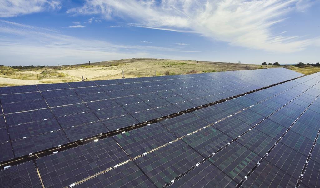
7 Outdoor test installations with the Nanosolar Utility Panel have been maintained since 2009 in a variety of geographic and climatic locations, including Nanosolar-operated and customer-operated installations in France, Germany, California, and Arizona. Figure 5: Nanosolar maintains a series of outdoor test installations in a geographically diverse range of locations and climates, including France, Germany, California, and Arizona. kwh energy delivery performance and normalized kwh/wp energy harvests have been tracked on an ongoing basis under identical conditions for crystalline silicon panels, conventional thin film panels, and Nanosolar Utility Panels. The gathered data shows that the performance of the Nanosolar Utility Panel is competitive with both. Based on flash test results and outdoor field performance measurements, Nanosolar Technical Notes on Performance Estimating are available to Nanosolar customers and summarize necessary input parameters for solar energy simulation programs such as PVSYST and PV*SOL. 5 Reliability The Nanosolar Utility Panel architecture safeguards the embedded solar cells from environmental impact. Extensive internal and third-party reliability testing has shown the Nanosolar Utility Panel to be highly reliable and extremely robust. The Nanosolar Utility Panel received successful certification upon its first submission to TÜV. Nanosolar Utility Panel Meets All Requirements According to IEC The Nanosolar Utility Panel is certified by TÜV Rheinland PTL, LLC Photovoltaic Testing Services according to IEC Thin-film terrestrial photovoltaic (PV) module design qualification and type approval; IEC Photovoltaic (PV) module safety qualification; and UL 1703 Electrical Safety and Class A Fire Resistance. The Nanosolar Edge Connector also received a separate TÜV certification. Nanosolar Utility Panel Engineered to Meet Testing In Excess of IEC As of the spring of 2010, the Nanosolar Utility Panel safely exceeds the IEC time and cycle testing limits. Extending the scope and intensity of gold plate TÜV reliability testing to gain even more confidence in >25-year panel durability, Nanosolar continuously performs internal panel and component stress tests in excess of the IEC standard. Internal reliability testing emphasizes test-to-fail methodology, as this provides a quantitative characterization of the panel s safety margins under extreme conditions. The Nanosolar Utility Panel - May
8 Rigorous Internal Testing Nanosolar continually performs a series of reliability tests, with a focus on component and material endurance, including: Temperature cycle testing Edge-box safety testing: damp heat, humidity freeze, and temperature cycling. Exposure of the Nanosolar Utility Panel to intense amounts of salt fog; Accelerated exposure of the panel edge seal, encapsulant, edge box and ribbon connectors to UV light (UV-A and UV-B) in an amount equivalent to 25 years; Accelerated testing of edge seal performance equivalent to 25 years of moisture and thermal cycling; Vibrational fatigue, bullet and sheer-force tests; Thermal freeze stress test. 6 Quality The Nanosolar quality system controls the entire production process from supplied raw materials to customer service and support. The manufacturing of the Nanosolar Utility Panel is based on fullyautomated assembly in a robotic factory with state-of-the-art in-line quality measurement controls. Incoming materials are qualified through extensive testing for performance and reliability before being released into production. All critical component and material attributes are clearly defined and regularly tested by Nanosolar suppliers. The results are confirmed in Nanosolar labs or independent labs. Process parameters on Nanosolar manufacturing equipment are the result of numerous tests, and are controlled with hundreds of sensors and lines of data, with the most critical aspects under statistical process control. Regular sampling and lab testing ensure that processes remain in tight control, and form the basis for continual improvements. Final flash testing of Nanosolar cells and panels confirm that the panels meet performance specifications, and also feeds data back to the processes where it is analyzed for potential process improvements. First In, First Out (FIFO) is built into the production system. Nanosolar data systems can track a panel and its components all the way back to a cell s raw materials and processing parameters. Tied together with regularly scheduled reliability testing, this enables Nanosolar to identify potential product issues well before a customer experiences them in a field installation. Cross functional teams solve manufacturing and quality issues using Toyota s 6 step problem solving methodology, entering them into a quality management system that provides a library of solutions and countermeasures for quick problem resolution. The Nanosolar quality system helps manage daily development and production, and also builds a vast library of data, tools and best practices for continuous improvements in the future. The Nanosolar Utility Panel - May

9 Figure 11: The assembly of the Nanosolar Utility Panel is completely automated in order to meet the highest quality standards. 7 Summary The Nanosolar Utility Panel is designed and developed specifically for utility-scale performance. By introducing a series of improvements to an industry-proven package with established reliability performance, the panel allows system integrators to significantly reduce BoS cost, and to achieve a gridparity levelized cost of energy in many utility-scale applications. The Nanosolar Utility Panel - May
APPENDIX V PRODUCT SHEETS
 National Institutes of Health Building 37 Modernization Bethesda, Maryland APPENDIX V PRODUCT SHEETS Katie L. McGimpsey Mechanical Option 1 of 4 BP 4160 160-Watt Monocrystalline Photovoltaic Module The
Optional Features. Linear Performance Warranty 10 Years product warranty 25 Years linear performance warranty
 Those who dream of a better future can help lead to a more meaningful and enriched world. As a leading solar module manufacturer in Korea, we never stop to achieve competitiveness through differentiation,
CP /240-MC4 User Manual
 CP-250-60-208/240-MC4 User Manual Chilicon Power LLC Jan 2014 1 CONTENTS Important Safety Instructions... 3 Safety Instructions... 3 CP-250 Microinverter System Introduction... 4 Inverter Label Information...
SOLON Corporation Potential Induced Degradation
 SOLON Corporation Potential Induced Degradation William Richardson NREL PVRW, February 1 th, 2011 SOLON at a Glance One of the largest manufacturers of solar modules in Europe Large scale rooftop and greenfield
Your Origin SLIVER system will be supplied with one of the following sets of panels:
 SLIVER3000 Solar System Panel Specifications Your Origin SLIVER system will be supplied with one of the following sets of panels: Manufacturer Mono Or Poly Size (Watts) Panels Required To Achieve Minimum
Type EN180-MS EN185-MS EN190-MS EN195-MS EN200-MS 13.5 A. Container Capacity Multiple Packing 40 feet (GP) 700 pcs / 28 pallets
 700 pcs / 28 pallets") Quality criteria and certificates IEC 61215, IEC 61730, CE-Certification, ISO 9001 and ILB-ISO 14001 Tolerance of nominal power (PMPP) 0+5%; classification range is ±2.5W 10 years product-warranty 5 years
Quality criteria and certificates IEC 61215, IEC 61730, CE-Certification, ISO 9001 and ILB-ISO 14001 Tolerance of nominal power (PMPP) 0+5%; classification range is ±2.5W 10 years product-warranty 5 years
Module Embedded Micro-inverter Smart Grid Ready Residential Solar Electric System
 1 Module Embedded Micro-inverter Smart Grid Ready Residential Solar Electric System This material is based upon work supported by the Department of Energy- under Award DE-EE0005344. Technology Summary
How to Evaluate PV Project Energy Yield
 How to Evaluate PV Project Energy Yield There are three main characteristics of a PV module that could affect the real energy generation of a PV plant: Temperature coefficient; Low light performance; IAM
Understanding Potential Induced Degradation for LG NeON Model
 Understanding Potential Induced Degradation for LG NeON Model Table of Contents 2 CONTENTS 1. Introduction 3 2. PID Mechanism 4 3. LG NeON model PID Characterization 5 4. Description 7 6. Test Result 11
Quality criteria and certificates
 Quality criteria and certificates IEC 61215, IEC 61730, CE-Certification, ISO 9001 and ILB-ISO 14001 Tolerance of nominal power (PMPP) 0+5%; classification range is ±2.5W 10 years product-warranty 5 years
SOLARLOK PV BAR Junction Box
 SOLARLOK PV BAR Junction Box Table of contents 1. SCOPE... 2 1.1. Content... 2 1.2. Qualification... 3 2. APPLICABLE DOCUMENTS... 3 2.1. TE Connectivity Documents... 3 2.2. Commercial Standard... 3 3.
Impact of Spectral Irradiance on Energy Yield of PV Modules Measured in Different Climates
 Impact of Spectral Irradiance on Energy Yield of PV Modules Measured in Different Climates 4th PV Performance Modelling and Monitoring Workshop 22nd and 23rd October, 2015 M. Schweiger TÜV Rheinland Energie
The Standard for over 40 Years
 Light Measurement The Standard for over 40 Years Introduction LI-COR radiation sensors measure the flux of radiant energy the energy that drives plant growth, warms the earth, and lights our world. The
PLOT PLAN INSTRUCTIONS ROOF MOUNT SOLAR AN ACCURATE PLOT PLAN IS NECESSARY TO PROCESS YOUR PERMIT
 PLOT PLAN INSTRUCTIONS ROOF MOUNT SOLAR Building Division 1855 Placer Street, Suite 102 Redding, California 96001 Phone: (530) 225-5761 Fax: (530) 245-6468 Inspection Request Line: (530) 244-5068 Web:
AWNING SYSTEM INSTALLATION INSTRUCTIONS ALL VERTICAL WALLS
 INSTALLATION MANUAL AWNING SYSTEM INSTALLATION INSTRUCTIONS ALL VERTICAL WALLS TABLE OF CONTENTS Table of Contents... 3 Components... 4 System Components... 6 Attachment Components... 7 Module Compatibility...
PORTABLE LED FLASHER WITH IMPLEMENTED BYPASS DIODE TESTER
 PORTABLE LED FLASHER WITH IMPLEMENTED BYPASS DIODE TESTER Daniel Schär 1, Franz Baumgartner ZHAW, Zurich University of Applied Sciences, School of Engineering, IEFE www.zhaw.ch/~bauf, Technikumstr. 9,
Upsolar Smart Modules
 Upsolar Smart Modules Optimized by Energy Improve ROI with No Upfront Cost Smart Modules optimized by Energy deliver more energy, active management and enhanced safety through state-ofthe-art module-embedded
Photovoltaic Glass Technologies
 Photovoltaic Glass Technologies Thin Glass for PV Modules: Mechanical Reliability Considerations Dr. James Webb Research Associate May 28, 2009 Agenda Introduction to thin glass Glass strength Reliability
Initial solar cell characterisation test and comparison with a LED-based solar simulator with variable flash speed and spectrum
 Loughborough University Institutional Repository Initial solar cell characterisation test and comparison with a LED-based solar simulator with variable flash speed and spectrum This item was submitted
OEM pressure transmitter For mobile working machines Model MH-3
 Electronic pressure measurement OEM pressure transmitter For mobile working machines Model MH-3 WIKA Data sheet PE 81.59 Applications Load monitoring Load moment limitation Hydraulic drive control Special
ELECTRICAL AND THERMAL MODELING OF JUNCTION BOXES
 ELECTRICAL AND THERMAL MODELING OF JUNCTION BOXES Max Mittag, Christoph Kutter, Stephan Hoffmann, Pascal Romer, Andreas J. Beinert, Tobias Zech Fraunhofer Institute for Solar Energy Systems ISE Heidenhofstr.
Optimized for perfection.
 TruPlasma MF series 7000 (G) Optimized for perfection. Outstanding layer quality, even with challenging and reactive DMS processes. Best in class. Trust is good, control is better having both is best of
BETTER DESIGN BETTER MATERIALS BETTER PROCESSES BETTER MODULES
 BETTER DESIGN BETTER MATERIALS BETTER PROCESSES BETTER MODULES TM FULL RANGE OF CERTIFIED MODULES Mono Crystalline Watt to 50 Watt Poly (Multi) Crystalline Watt to 80 Watt Glass Cells High Efficiency A-Grade
Building a Solar PV Roadmap The National Academies July 29, Ken Zweibel GW Solar Institute The George Washington University
 Building a Solar PV Roadmap The National Academies July 29, 2009 Ken Zweibel GW Solar Institute The George Washington University zweibel@gwu.edu Purpose Accelerate PV progress in order to meet national
Solar Simulation Standards and QuickSun Measurement System. Antti Tolvanen Endeas Oy
 Solar Simulation Standards and QuickSun Measurement System Antti Tolvanen Endeas Oy 1 Endeas in Brief QuickSun Solar Simulators Technology invented 1996 in Fortum (www.fortum.com) Endeas Oy licenses technology
TESTING AND MEASURING EQUIPMENT/ALLOWED SUBCONTRACTING
 IEC SYSTEM FO CONFOMITY TESTING AND CETIFICATION OF ELECTICAL COMMITTEE OF TESTING LABOATOIES TESTING AND MEASUING /ALLOWED SUBCONTACTING = equired by Lab S = May be subcontracted 10.1 Visual inspection
Voltage Sag Immunity Compliance Certificate PULS QS10.241, QS A1, QS C1
 PSL File QS10_241 Last modified: 19 December 2011 PSL Power Standards Laboratory www.powerstandards.com 2020 Challenger Drive #100 Alameda, CA 94501 USA TEL ++1-510-522-4400 FAX ++1-510-522-4455 SEMI F47-0706
Accelerating Growth and Cost Reduction in the PV Industry
 Accelerating Growth and Cost Reduction in the PV Industry PV Technology Roadmaps and Industry Standards An Association s Approach Bettina Weiss / SEMI PV Group July 29, 2009 SEMI : The Global Association
Precision and High Reliability Thermostats Issue 3. Datasheet. Table of Contents
 Precision and High Reliability Thermostats DESCRIPTION Thermostats can provide either temperature control or overtemperature protection by breaking electrical contact when a specified temperature is reached.
SILICon IrrADIAnCe SenSor
 Measurement of Solar Silicon irradiance sensors (Si sensor) show a cost-effective, but rugged and reliable solution for the measurement of solar irradiance, especially for the monitoring of Photovoltaic
TEST REPORT IEC 61215: nd Edition Crystalline Silicon Terrestrial Photovoltaic (PV) Modules - Design Qualification and Type Approval
 Modules - Design Qualification and Type Approval") Test Report issued under the responsibility of: TEST REPORT IEC 61215: 2005 2nd Edition Crystalline Silicon Terrestrial Photovoltaic (PV) Modules - Design Qualification and Type Approval Report Reference
Test Report issued under the responsibility of: TEST REPORT IEC 61215: 2005 2nd Edition Crystalline Silicon Terrestrial Photovoltaic (PV) Modules - Design Qualification and Type Approval Report Reference
Test Report. File No.: SHV01023/16 Test Report No.: Taizhou, Zhejiang , P.R. China
 Applicant... : Manufacturer... : Order No.... : Zhejiang ERA Solar Technology Co., Ltd. Sihai Road, Huangyan Economic Development Zone Taizhou, Zhejiang 318020, P.R. China Zhejiang ERA Solar Technology
Advances in Silicon Technology Enables Replacement of Quartz-Based Oscillators
 Advances in Silicon Technology Enables Replacement of Quartz-Based Oscillators I. Introduction With a market size estimated at more than $650M and more than 1.4B crystal oscillators supplied annually [1],
Temposonics. E-Series Model ER. Magnetostrictive, Absolute, Non-contact Linear-Position Sensors. Analog and Start/Stop Outputs.
 Temposonics Magnetostrictive, Absolute, Non-contact Linear-Position Sensors Analog and Start/Stop Outputs SENSORS Document Part Number: 550996 Revision E Data Sheet FEATURES Linear, Absolute Measurement
2520 Pulsed Laser Diode Test System
 Complete pulse test of laser diode bars and chips with dual photocurrent measurement channels 0 Pulsed Laser Diode Test System Simplifies laser diode L-I-V testing prior to packaging or active temperature
Evaluation of high power laser diodes for space applications: effects of the gaseous environment
 Evaluation of high power laser diodes for space applications: effects of the gaseous environment Jorge Piris, E. M. Murphy, B. Sarti European Space Agency, Optoelectronics section, ESTEC. M. Levi, G. Klumel,
60 cell LG300N1K-G4. Key Features. High Power Output. Enhanced Performance Warranty. Outstanding Durability. Aesthetic Roof
 EN LG300N1K-G4 60 cell LG s new module, NeON 2 Black, adopts Cello technology. Cello technology replaces 3 busbars with 12 thin wires to enhance power output and reliability. NeON 2 Black demonstrates
TUV Rheinland (India) Pvt. Ltd. Product Safety & Quality. Test Report
 Pvt. Ltd. Product Safety & Quality. Test Report") TUV Rheinland (India) Pvt. Ltd. Product Safety & Quality Test Report Photovoltaic module Testing TÜV Report No. 19631307.002 Bangalore, May 2017 Certificate No. T -1543 2 / 17 Contents CONTENTS... 2
TUV Rheinland (India) Pvt. Ltd. Product Safety & Quality Test Report Photovoltaic module Testing TÜV Report No. 19631307.002 Bangalore, May 2017 Certificate No. T -1543 2 / 17 Contents CONTENTS... 2
Committee E44 on Solar, Geothermal and Other Alternative Energy Sources
 Committee E44 on Solar, Geothermal and Other Alternative Energy Sources Formed in 1978 Meets once a year during November Committee Week Current membership of approximately 70 Jurisdiction over 49 standards
SolarWorld Africa (Pty) Ltd Davis & Shirtliff Kenya
 Ltd Davis & Shirtliff Kenya") SOLARWORLD AFRICA (PTY) LTD DEAN LUNDALL SolarWorld Africa (Pty) Ltd Davis & Shirtliff Kenya Overview of SolarWorld SolarWorld: Over 40 years of REAL VALUE We are a global player in the solar industry
SOLARWORLD AFRICA (PTY) LTD DEAN LUNDALL SolarWorld Africa (Pty) Ltd Davis & Shirtliff Kenya Overview of SolarWorld SolarWorld: Over 40 years of REAL VALUE We are a global player in the solar industry
Commercial Aviation Interconnects. & Value-Added Services CAB-6.18
 Commercial Aviation Interconnects & Value-Added Services CAB-6.18 AirBorn engineers design & fabricate to the highest aerospace standards imaginable so airline passengers can sit back, relax and enjoy
Calculating AC Line Voltage Rise for IQ-Series Micros with Q Cable
 TECHNICAL BRIEF Calculating AC Line Voltage Rise for IQ-Series Micros with Q Cable Overview This technical brief presents voltage rise guidelines for dedicated PV branch circuits and methods for calculating
apogeeinstruments.com Introducing the PV-100 PV Monitoring Package
 apogeeinstruments.com Introducing the PV-100 PV Monitoring Package PV Monitoring Package Introducing the new PV monitoring package (PV-100) designed to work with an SMA cluster controller and offered at
RFID Antenna Family. RFID antennas for fixed readers. Comprehensive RFID antenna portfolio for diverse application needs
 SPECIFICATION SHEET RFID Antenna Family RFID antennas for fixed readers Comprehensive RFID antenna portfolio for diverse application needs Motorola s family of Radio Frequency Identification (RFID) Antennas
The RSM shall be extensively used in field & laboratory for verification of the accuracy of all types of single-phase energy meters.
 TECHNICAL SPECIFICATION FOR PORTABLE ELECTRONIC REFERENCE STANDARD METER (ERS) FOR TESTING OF SINGLE PHASE KILOWATT HOUR ENERGY METERS (ACCURACY CLASS 0. 2) 1. SCOPE: The specification covers the requirement
APS M1P Single-phase Micro-inverter Installation and User Manual
 APS M1P Single-phase Micro-inverter Installation and User Manual Version: 2.0 ALTENERGY POWER SYSTEM, INC. All rights reserved 1 Contact Information ALTENERGY POWER SYSTEM Inc. 1 Yatai Road, Jiaxing, PR
THE DESERT KNOWLEDGE AUSTRALIA SOLAR CENTRE: HIGH VOLTAGE EFFECTS ON INVERTER PERFORMANCE.
 THE DESERT KNOWLEDGE AUSTRALIA SOLAR CENTRE: HIGH VOLTAGE EFFECTS ON INVERTER PERFORMANCE. Paul Rodden, Ga Rick Lee & Lyndon Frearson CAT Projects PO Box 8044, Desert Knowledge Precinct, Alice Springs,
USER S GUIDE. for MIDDLETON SOLAR SECONDARY STANDARD PYRANOMETER WITH INTEGRATING CAVITY DETECTOR
 Part No. 111.1008 CE 2016 USER S GUIDE for MIDDLETON SOLAR ER08-S and ER08-SE SECONDARY STANDARD PYRANOMETER WITH INTEGRATING CAVITY DETECTOR Date: Dec. 2016 Version: 1.7 Middleton Solar, made in Australia.
Customized Sensors. OEM Custom-designed Sensors...from the leader in the measurement of mechanical parameters
 Customized Sensors OEM Custom-designed Sensors...from the leader in the measurement of mechanical parameters OEM Custom-designed Sensors Caught in a design dilemma? Are you looking for sensing technology
Performance Loss of PV systems. Giorgio Belluardo
 Performance Loss of PV systems Giorgio Belluardo Content Importance of accurate estimation of PL Mechanisms behind performance loss Statistics Methodologies to assess PLR Novel method for estimation of
SWF DV/DT Solutions Sinewave Filters. N52 W13670 NORTHPARK DR. MENOMONEE FALLS, WI P. (262) F. (262)
 F. (262)") SWF DV/DT Solutions Sinewave Filters N52 W13670 NORTHPARK DR. MENOMONEE FALLS, WI 53051 P. (262) 754-3883 F. (262) 754-3993 www.apqpower.com Does your application use variable frequency drives for improved
SWF DV/DT Solutions Sinewave Filters N52 W13670 NORTHPARK DR. MENOMONEE FALLS, WI 53051 P. (262) 754-3883 F. (262) 754-3993 www.apqpower.com Does your application use variable frequency drives for improved
Proprietary Calibration Certificate
 Calibration Mark: 1003196SBR0813 1/6 Proprietary Calibration Certificate Object: thin film solar cell Manufacturer: Solibro Serial number: 130618-3A Internal serial number: SBR003 Calibration mark: 1003196SBR0813
RFID Antenna Family. RFID antennas for fixed readers. Comprehensive RFID antenna portfolio for diverse application needs
 SPECIFICATION SHEET RFID Antenna Family RFID antennas for fixed readers Comprehensive RFID antenna portfolio for diverse application needs Motorola s family of Radio Frequency Identification (RFID) Antennas
Application Note: String sizing Conext CL Series
 : String sizing Conext CL Series 965-0066-01-01 Rev A DANGER RISK OF FIRE, ELECTRIC SHOCK, EXPLOSION, AND ARC FLASH This Application Note is in addition to, and incorporates by reference, the installation
Real-time non-contact wet or dry thickness measurement of pressure sensitive, water based, hot melt, laminating and other adhesives
 Real-time non-contact wet or dry thickness measurement of pressure sensitive, water based, hot melt, laminating and other adhesives Novel In-line coating thickness measurement technology Uses Ruggedized
Potential Induced Degradation (PID) Study of. Fresh and Accelerated Stress Tested Photovoltaic Modules. Sandhya Goranti
 Study of. Fresh and Accelerated Stress Tested Photovoltaic Modules. Sandhya Goranti") Potential Induced Degradation (PID) Study of Fresh and Accelerated Stress Tested Photovoltaic Modules by Sandhya Goranti A Thesis Presented in Partial Fulfillment of the Requirements for the Degree Master
Potential Induced Degradation (PID) Study of Fresh and Accelerated Stress Tested Photovoltaic Modules by Sandhya Goranti A Thesis Presented in Partial Fulfillment of the Requirements for the Degree Master
Tested and ready to use Quality from a single-source
 Tested and ready to use Quality from a single-source 2 Cable fabrication 100% tested and ready to use for all-round certainty Quickly assembled and reliable in operation that is how machine components
PID: an invisible danger for solar systems and how to prevent it
 PID: an invisible danger for solar systems and how to prevent it PV Magazine Quality Roundtable Intersolar, st June Andrea Viaro, Head of Technical Service & Product Mgmt. Europe Total Quality Management.
Company Introduction
 Company Introduction Copyright 2012 by SolarPark Korea Co., Ltd. ALL RIGHTS RESERVED. No part of this publication may be reproduced, stored in a retrieval system, or transmitted in any form or by any means
1) Solar simulator with I-V measurement setup and software
 Solar simulator with I-V measurement setup and software") Department of Optoelectronics, University of Kerala, Kariavattom, Thiruvananthapuram, Kerala, India 695581, Ph: 91 471 2308167 OPTO/Nanophotonics-Phase II/P-1/2014-15 Quotation Notice Quotations are invited
Department of Optoelectronics, University of Kerala, Kariavattom, Thiruvananthapuram, Kerala, India 695581, Ph: 91 471 2308167 OPTO/Nanophotonics-Phase II/P-1/2014-15 Quotation Notice Quotations are invited
ID SERIES OUTDOOR INDUSTRIAL DIPOLE ANTENNA
 ID SERIES OUTDOOR INDUSTRIAL DIPOLE ANTENNA Phone: (8) 736-6677 / Int: +1 541-471-6256 Email: info@linxtechnologies.com / Address: 159 Ort Lane, Merlin, OR 97532 ID SERIES OUTDOOR INDUSTRIAL DIPOLE ANTENNA
DC PV Arc fault detection Unit
 DC PV Arc fault detection Unit Installation, usage and other information Author: Peter v. Galen, Product Manager Date: 15-09-2014 Revision: B 1. Introduction The National Electrical Code 2011 states arc-fault
Laboratory 2: PV Module Current-Voltage Measurements
 Laboratory 2: PV Module Current-Voltage Measurements Introduction and Background The current-voltage (I-V) characteristic is the basic descriptor of photovoltaic device performance. A fundamental understanding
Measurement of the thickness of thin foils and testing of the heat sealing of food and medicinal packaging
 ECNDT 2006 - Th.3.8.3 Measurement of the thickness of thin foils and testing of the heat sealing of food and medicinal packaging Sven MÜLLER, arsenco ag, Altdorf, Switzerland Layer thickness measurement
HARTING Coaxial and Metric Connectors
 HARTING Coaxial and Metric Connectors HARTING Worldwide Transforming customer wishes into concrete solutions The HARTING Technology Group is skilled in the fields of electrical, electronic and optical
Sabritec Qualification Test Report Summary
 Sabritec Qualification Summary Qualification of Multimode Fiber Optic Termini, and Type 1, Category 2 Connectors per ARINC Specification 801 QTR #705 03-27-08 Revision Page Paragraph Description of Revision
Test Report. File No.: SHV01032/18-02 Test Report No.:
 File No.: SHV01032/18-02 No.: 492011003.001 Applicant... : Manufacturer 1... : Manufacturer 2... : Order No.... : Suzhou Akcome Optronics Science &Technology Co., Ltd. Jintang Rd, Zhangjiagang Economic
Oriel Sol3A Class AAA Solar Simulators
 Leveraging over 40 years of experience in light source and supply design, Newport s Output beam sizes 2x2", 4x4, 6x6, 8x8", and x " Factory certified Class AAA CW systems Calibration certificate validating
Outline. Grounding Washer, Electrical Equipment Bond (WEEB) Acme Cable Clips Acme Conduit Entry (ACE) Questions
 Acme Cable Clips Acme Conduit Entry (ACE) Questions") www.we-llc.com Outline Grounding Washer, Electrical Equipment Bond (WEEB) Acme Cable Clips Acme Conduit Entry (ACE) Questions Bonding & Grounding Grounding Terms Equipment Grounding: The National Electrical
www.we-llc.com Outline Grounding Washer, Electrical Equipment Bond (WEEB) Acme Cable Clips Acme Conduit Entry (ACE) Questions Bonding & Grounding Grounding Terms Equipment Grounding: The National Electrical
RD1000 Ground Probing Radar
 RD1000 Ground Probing Radar CONTENTS Product Introduction Product Features Competitor Analysis Customers Models, Pricing & Availability Promotional Material Practical Demonstration What to do now Summary
1. Executive Summary. 2. Introduction. Selection of a DC Solar PV Arc Fault Detector
 Selection of a DC Solar PV Arc Fault Detector John Kluza Solar Market Strategic Manager, Sensata Technologies jkluza@sensata.com; +1-508-236-1947 1. Executive Summary Arc fault current interruption (AFCI)
Sunny Smile with Hyundai
 Happy Energy for the Future! Sunny Smile with Hyundai Advanced Green Solution beyond the world Hyundai Heavy Industries Happy Energy for the Future Hyundai Heavy Industries provides green solution for
Turning the wheels of your success
 INDUSTRIAL SERVICES Turning the wheels of your success A comprehensive package of integrated services combining traditional certification and inspection with innovative business solutions based on the
NEW TOUGHEST WIND SENSORS THE WORLD S 1:2
 F T 74 2 D ATA S H E E T NEW S U R FA C E M O U N T D E S I G N E D F O R I N T E G R AT I O N THE WORLD S TOUGHEST WIND SENSORS WWW.FTTECHNOLOGIES.COM 1:2 PROVEN IT LOOKS DIFFERENT BECAUSE IT IS DIFFERENT
Wire management is key to productivity in wafer production
 Wire management is key to productivity in wafer production siemens.com/solar-industry Customer: Meyer Burger Place, Country: Gwatt (Thun), Switzerland Industries: Solar Used Products: SIMATIC WinAC, IFP1500
Hermetic Packaging Solutions using Borosilicate Glass Thin Films. Lithoglas Hermetic Packaging Solutions using Borosilicate Glass Thin Films
 Hermetic Packaging Solutions using Borosilicate Glass Thin Films 1 Company Profile Company founded in 2006 ISO 9001:2008 qualified since 2011 Headquarters and Production in Dresden, Germany Production
INDUSTREX (installed and tested prior to shipping) Windows 7 Ultimate 64 bit Filter
 Windows 7 Ultimate 64 bit Filter") HPX-PRO For Non-Destructive Testing IMAGING PLATES When it comes to portable digital imaging with the HPX-PRO, there is no question that you also need rugged imaging plates that can withstand harsh mobile
HPX-PRO For Non-Destructive Testing IMAGING PLATES When it comes to portable digital imaging with the HPX-PRO, there is no question that you also need rugged imaging plates that can withstand harsh mobile
Section 16621A - AUTOMATIC TRANSFER SWITCH. Part 1 General
 Section 16621A - AUTOMATIC TRANSFER SWITCH Part 1 General 1.01 One 600 Amp, 3 Phase, 480 Volt Automatic Transfer Switch (ATS) shall be provided with gasketed enclosure. The ATS shall consist of an inherently
Growatt 2000TL. Input Data Max. DC power Max. DC voltage. PV voltage range MPPT. Full load MPP-Voltage range
 Growatt 2000TL Maximum efficiency of 97% and wide inpunt voltage range Internal DC switch Transformerless GT topology Compact design Multi MPP controller MTL - String Bluetooth / RF technology / ZigBee
Pag 1 of 15. Eurotest Laboratori S.r.l. Via Marconi, Brugine (PD) Italy
 Italy") Pag 1 of 15 TEST REPORT IEC 82/685/NP (not ACCREDIA accredited) IEC 60068-2-78 IEC 61215 IEC 61730-2 System voltage durability test for crystalline silicon modules Design qualification and type approval
Pag 1 of 15 TEST REPORT IEC 82/685/NP (not ACCREDIA accredited) IEC 60068-2-78 IEC 61215 IEC 61730-2 System voltage durability test for crystalline silicon modules Design qualification and type approval
Crystallize Your Visions in the Photovoltaic and Semiconductor World CCIC. Competence Center for Industrial Crystal Growing Systems
 Crystallize Your Visions in the Photovoltaic and Semiconductor World CCIC Competence Center for Industrial Crystal Growing Systems Our team and equipment Multinational team PhD. scientists Physicists and
TRENDS IN MAGNET WIRE TERMINATION White Paper
 TRENDS IN MAGNET WIRE TERMINATION TRENDS IN MAGNET WIRE TERMINATION Magnet wire is widely used in windings of electric motors, transformers, inductors, generators, electromagnets, coils and other devices.
SOLARONIX. Solixon A-1525-V
 SOLARONIX Solixon A-1525-V Based on Solaronix' exclusive light engine, our solar simulation equipment delivers a perfect and continuous artificial sunlight 24/7, allowing for accurate stability and performance
INTREPID Model 336 Digital Microwave Link
 Southwest Microwave, Inc. 9055 S. McKemy Street Tempe, Arizona 85284 USA +1(480) 783-0201 Fax +1(480) 783-0401 Product Specifications INTREPID Model 336 Digital Microwave Link Purpose of document This
Flash Stamp Machine T1511M User Manual
 Flash Stamp Machine T1511M User Manual Declaration of conformity (Europe only) We, Trodat GmbH Linzer Straße 156 A-4600 Wels hereby declare that the Flash Stamp Machine model T1511M is CE certified respectively
Performance of SolarPod TM Crown Dr. Mouli Vaidyanathan, PhD PE, Eagan Minnesota 55123
 Performance of SolarPod TM Crown Dr. Mouli Vaidyanathan, PhD PE, Eagan Minnesota 55123 Contents Contents... 1 Introduction:... 1 Purpose:... 1 Literature Review:... 2 Procedure:... 3 Field case 1 (SolarPod
Standby Power. Primer
 Standby Power Primer Primer Table of Contents What is Standby Power?...3 Why is Standby Power Important?...3 How to Measure Standby Power...4 Requirements for a Measurement...4 Standby Measurement Challenges...4
Wisconsin Place Residential Chevy Chase, MD
 Wisconsin Place Residential Chevy Chase, MD Jenna Marcolina Senior Thesis Presentation 2008 The Pennsylvania State University Presentation Outline Project Overview Project Overview WPR is part of a 1.1
MC2301. Features and Benefits. Promotional Highlights TUBE POWER AMPLIFIER MCINTOSH LABORATORY INC., 2 CHAMBERS STREET, BINGHAMTON, NEW YORK 13903
 MC2301 Product Preview Page 1 McIntosh Laboratory, Inc., Binghamton, NY 13903 Design Engineering Department PRODUCT PREVIEW MC2301 TUBE POWER AMPLIFIER Project 1336 Promotional Highlights 300 Watts Mono
paint for coil coating
 paint for coil coating SUSTAINABLE CHEMISTRY DEDICATED TO INDUSTRIAL PAINTING. Environmentally friendly. In the Paint Division of Condoroil Chemical, sustainability is not only a word, it is a life style.
Military & Defense Interconnects. & Value-Added Services MDEFB-6.18
 Military & Defense Interconnects & Value-Added Services MDEFB-6.18 AirBorn components have been an integral part of system solutions created to defend America and her allies for over half a century. Engineering
Understanding Infrared Camera Thermal Image Quality
 Access to the world s leading infrared imaging technology Noise { Clean Signal www.sofradir-ec.com Understanding Infared Camera Infrared Inspection White Paper Abstract You ve no doubt purchased a digital
FT702LT HEAVY DUTY WIND SPEED AND WIND DIRECTION IN ONE TOUGH PACKAGE FT702LT. series
 FT702LT U L T R A S O N I C HEAVY DUTY W I N D S E N S O R WIND SPEED AND WIND DIRECTION IN ONE TOUGH PACKAGE FT702LT series Proven High Availability The FT702LT ultrasonic anemometer is the result of
TECHNICAL PRODUCT DATASHEET
 FORM-ENG-0018 REV A 06-02-03 ISO 9001 CERTIFIED Phone: (352) 629-5020 or 800-533-3569 Fax: (352)-629-2902 SUITABLE FOR OEM DISTRIBUTION ONLY TECHNICAL PRODUCT DATASHEET High Density PDM 21 Output / 10
Gap Analysis towards A Design Qualification Standard Development for Grid-Connected. Photovoltaic Inverters
 Gap Analysis towards A Design Qualification Standard Development for Grid-Connected Photovoltaic Inverters by Sai Balasubramanian Alampoondi Venkataramanan A Thesis Presented in Partial Fulfillment of
High-Reliability and Environment Qualified Components
 High-Reliability and Environment Qualified Components Introduction Ruggedness and reliability have been designed in across our product lines and proven in the field. This section of our catalog provides
About Us. 65 Years in Business. Products in Service Worldwide. Fully Integrated Company. Design / R&D / Manufacturing / Testing / Support
 About Us 65 Years in Business Products in Service Worldwide Fully Integrated Company Design / R&D / Manufacturing / Testing / Support Custom Design & Manufacturing Centrally Located in the USA for Faster
APS M1P Single-phase Micro-inverter Installation and User Manual
 APS M1P Single-phase Micro-inverter Installation and User Manual Version: 1.0 ALTENERGY POWER SYSTEM, INC. All rights reserved 1 Contact Information ALTENERGY POWER SYSTEM Inc. 1 Yatai Road, Jiaxing, PR
Slim compact safety relay
 Slim compact safety relay SF RELAYS Slim type Max..9 Max..9 Max.. Max..99 Max.. Max.. mm inch FEATURES Forcibly guide contact structure (EN Class A TÜV recognized) Slim profile (mm inch) Compact size with
Reference: Photovoltaic Systems, p
 PV systems are comprised of building blocks of cells, modules and arrays to form a DC power generating unit with specified electrical output. Reference: Photovoltaic Systems, p. 115-118 Reference: Photovoltaic