VTU NOTES QUESTION PAPERS NEWS RESULTS FORUMS
|
|
|
- Monica Tucker
- 5 years ago
- Views:
Transcription
1 Unit 8 : ROBOTICS INTRODUCTION Robots are devices that are programmed to move parts, or to do work with a tool. Robotics is a multidisciplinary engineering field dedicated to the development of autonomous devices, including manipulators and mobile vehicles. The Origins of Robots Year 1250 Bishop Albertus Magnus holds banquet at which guests were served by metal attendants. Upon seeing this, Saint Thomas Aquinas smashed the attendants to bits and called the bishop a sorcerer. Year 1640 Descartes builds a female automaton which he calls Ma fille Francine. She accompanied Descartes on a voyage and was thrown overboard by the captain, who thought she was the work of Satan. Year 1738 Jacques de Vaucanson builds a mechanical duck quack, bathe, drink water, eat grain, digest it and void it. Whereabouts of the duck are unknown today. Year 1805 Doll, made by Maillardet, that wrote in either French or English and could draw landscapes Year 1923 Karel Capek coins the term robot in his play Rossum s Universal Robots (R.U.R). Robot comes from the Czech word robota, which means servitude, forced labor. Year 1940 Sparko, the Westinghouse dog, was developed which used both mechanical and electrical components.
2 Year 1950 s to 1960 s Computer technology advances and control machinery is developed. Questions Arise: Is the computer an immobile robot? Industrial Robots created. Robotic Industries Association states that an industrial robot is a re-programmable, multifunctional manipulator designed to move materials, parts, tools, or specialized devices through variable programmed motions to perform a variety of tasks Year 1956 Researchers aim to combine perceptual and problem-solving capabilities, using computers, cameras, and touch sensors. The idea is to study the types of intelligent actions these robots are capable of. A new discipline is born: A.I. Year 1960 Shakey is made at Stanford Research Institute International. It contained a television camera, range finder, on-board logic, bump sensors, camera control unit, and an antenna for a radio link. Shakey was controlled by a computer in a different room. The first industrial robot: UNIMATE Year 1954 The first programmable robot is designed by George Devol, who coins the term Universal Automation. He later shortens this to Unimation, which becomes the name of the first robot company (1962). Year 1978 The Puma (Programmable Universal Machine for Assembly) robot is developed by Unimation with a General Motors design support Year 1980s The robot industry enters a phase of rapid growth. Many institutions introduce programs and courses in robotics. Robotics courses are spread across mechanical engineering, electrical engineering, and computer science departments. Year 1995-present Emerging applications in small robotics and mobile robots drive a second growth of start-up companies and research 2003 NASA s Mars Exploration Rovers will launch toward Mars in search of answers about the history of water on Mars
3 Categories in Robot Studies Definition An industrial robot is a general purpose, programmable machine possessing certain anthropomorphic characteristics. The most typical anthropomorphic or human like, characteristics of a robot is its arm. This arm, together with the robots capacity to be programmed, make it ideally suited to a variety of production tasks, including machine loading, spot welding, spray painting and assembly. The robot can be programmed to perform sequence of mechanical motions, and it can repeat that motion sequence over the over until programmed to perform some other job. An industrial robot is a general purpose programmable machine that possesses certain anthropomorphic features The most apparent anthropomorphic feature of an industrial robot is its mechanical arm, or manipulator Robots can perform a variety of tasks such as loading and unloading machine tools, spot welding automobile bodies, and spray painting Robots are typically used as substitutes for human workers in these tasks An industrial robot is a programmable, multi-functional manipulator designed to move materials, parts, tools, or special devices through variable programmed motions for the performance of a variety of tasks. An industrial robot consists of a mechanical manipulator and a controller to move it and perform other related functions The mechanical manipulator consists of joints and links to position and orient the end of the manipulator relative to its base The controller operates the joints in a coordinated fashion to execute a programmed work cycle A robot joint is similar to a human body joint It provides relative movement between two parts of the body Typical industrial robots have five or six joints, Manipulator joints: classified as linear or rotating

4 How are robots used? Industrial robots do tasks that are hazardous or menial. Exploratory robots explore environments that are inhospitable to humans such as space, military targets or areas of search and rescue operations. Assistive robots help handicapped individuals by assisting with daily tasks including wheelchair navigation and feeding. ROBOT ANATOMY Translational motion Linear joint (type L) Orthogonal joint (type O) Rotary motion Rotational joint (type R) Twisting joint (type T) Revolving joint (type V) Types of joints (a) Linear joint (type L joint), (b) orthogonal joint (type O joint ) (c) Rotational joint (type R joint )

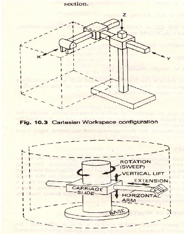
5 (d) Twisting joint ( type T joint) (e) revolving joint (type V joint) Robot Physical Configuration Industrial robots come in a variety of shapes and sizes. They are capable of various arm manipulations and they possess different motion systems. Classification based on Physical configurations Four basic configurations are identified with most of the commercially available industrial robots 1. Cartesian configuration: A robot which is constructed around this configuration consists of three orthogonal slides, as shown in fig. the three slides are parallel to the x, y, and z axes of the Cartesian coordinate system. By appropriate movements of these slides, the robot is capable of moving its arm at any point within its three dimensional rectangularly spaced work space. 2. Cylindrical configuration: in this configuration, the robot body is a vertical column that swivels about a vertical axis. The arm consists of several orthogonal slides which allow the arm to be moved up or down and in and out with respect to the body. This is illustrated schematically in figure. 3. Polar configuration: this configuration also goes by the name spherical coordinate because the workspace within which it can move its arm is a partial sphere as shown in figure. The robot has a rotary base and a pivot that can be used to raise and lower a telescoping arm. 4. Jointed-arm configuration: is combination of cylindrical and articulated configurations. This is similar in appearance to the human arm, as shown in fig. the arm consists of several
6 straight members connected by joints which are analogous to the human shoulder, elbow, and wrist. The robot arm is mounted to a base which can be rotated to provide the robot with the capacity to work within a quasi-spherical space.
7 Basic Robot Motions Whatever the configuration, the purpose of the robot is to perform a useful task. To accomplish the task, an end effector, or hand, is attached to the end of the robots arm. It is the end effector which adapts the general purpose robot to a particular task. To do the task, the robot arm must be capable of moving the end effectors through a sequence of motions and positions. There are six basic motions or degrees of freedom, which provide the robot with the capability to move the end effectors through the required sequences of motions. These six degree of freedom are intended to emulate the versatility of movement possessed by the human arm. Not all robots are equipped with the ability to move in all sex degrees. The six basic motions consist of three arm and body motions and three wrist motions. Arm and body motions 1. Vertical traverse: Up and down motion of the arm, caused by pivoting the entire arm about a horizontal axis or moving the arm along a vertical slide. 2. Radial traverse: extension and retraction of the arm (in and out movement) 3. Rotational traverse: rotation about the vertical axis (right or left swivel of the robot arm)
8 Wrist Motion Wrist swivel: Rotation of the wrist Wrist bend: Up or down movement of the wrist, this also involves rotation movement. Wrist yaw: Right or left swivel of the wrist. Advantages and disadvantages of 5 types of robots Configurations Advantages Disadvantages Cartesian coordinates Cylindrical coordinates 3 linear axes, easy to visualize,rigid structure,easy programming 2 linear axes +1 rotating can reach all around itself,reach and height axes rigid,rotational axis easy to seal Can only reach front of itself, requirse long room space. Can t reach above itself, base rotation axis as less rigid, linear axis is hard to seal. SCARA coordinates 1 linear + 2 rotational axes is rigid, large work space area for floor space Spherical coordinates Revolve coordinates 1 linear + 2 rotational axes, long horizontal reach 3 rotational axes can reach above or below obstacles. 2 ways to reach point,difficult to program offline, highly complex arm Can t reach around obstacles.short vertical length Difficult to program off-line, most complex manipulator
9 Motion system 1. Point-to-point (PTP) control robot: is capable of moving from one point to another point. The locations are recorded in the control memory. PTP robots do not control the path to get from one point to the next point. Common applications include component insertion, spot welding, hole drilling, machine loading and unloading, and crude assembly operations. 2. Continuous-path (CP) control robot: with CP control, the robot can stop at any specified point along the controlled path. All the points along the path must be stored explicitly in the robot s control memory. Typical applications include spray painting, finishing, gluing, and arc welding operations. 3. Controlled-path robot: the control equipment can generate paths of different geometry such as straight lines, circles, and interpolated curves with a high degree of accuracy. All controlled-path robots have a servo capability to correct their path. Technical Features Of An Industrial Robot The technical features of an industrial robot determine its efficiency and effectiveness at performing a given task. The following are some of the most important among these technical features. Degree of Freedom (D.O.F) - Each joint on the robot introduces a degree of freedom. Each dof can be a slider, rotary, or other type of actuator. Robots typically have 5 or 6 degrees of freedom. 3 of the degrees of freedom allow positioning in 3D space, while the other 2or 3 are used for orientation of the end effector. 6 degrees of freedom are enough to allow the robot to reach all positions and orientations in 3D space. 5 D.O.F requires a restriction to 2D space, or else it limits orientations. 5 D.O.F robots are commonly used for handling tools such as arc welders. Work Volume/Workspace - The robot tends to have a fixed and limited geometry. The work envelope is the boundary of positions in space that the robot can reach. For a Cartesian robot (like an overhead crane) the workspace might be a square, for more sophisticated robots the workspace might be a shape that looks like a clump of intersecting bubbles.
10

11 Precision Movement The precision with which the robot can move the end of its wrist is a critical consideration in most applications. In robotics, precision of movement is a complex issue, and we will describe it as consisting of three attributes: 1. Control resolution 2. Accuracy 3. Repeatability Control Resolution - This is the smallest change that can be measured by the feedback sensors, or caused by the actuators, whichever is larger. If a rotary joint has an encoder that measures every 0.01 degree of rotation, and a direct drive servo motor is used to drive the joint, with a resolution of 0.5 degrees, then the control resolution is about 0.5 degrees (the worst case can be ). Accuracy - This is determined by the resolution of the workspace. If the robot is commanded to travel to a point in space, it will often be off by some amount, the maximum distance should be considered the accuracy. Repeatability - The robot mechanism will have some natural variance in it. This means that when the robot is repeatedly instructed to return to the same point, it will not always stop at the same position.
12 A portion of a linear positioning system axis, with showing control resolution, accuracy, and repeatability Speed - refers either to the maximum velocity that is achievable by the TCP, or by individual joints. This number is not accurate in most robots, and will vary over the workspace as the geometry of the robot changes. Weight Carrying Capacity (Payload) - The payload indicates the maximum mass the robot can lift before either failure of the robots, or dramatic loss of accuracy. It is possible to exceed the maximum payload, and still have the robot operate, but this is not advised. When
13 the robot is accelerating fast, the payload should be less than the maximum mass. This is affected by the ability to firmly grip the part, as well as the robot structure, and the actuators. The end of arm tooling should be considered part of the payload. Types Of Drive Systems There are three basic drive system used in commercially available robots: 1. Hydraulic drive: gives a robot great speed and strength. These systems can be designed to actuate linear or rotational joints. The main disadvantage of a hydraulic system is that it occupies floor space in addition to that required by the robot. 2. Electric drive: compared with a hydraulic system, an electric system provides a robot with less speed and strength. Accordingly, electric drive systems are adopted for smaller robots. However, robots supported by electric drive systems are more accurate, exhibit better repeatability, and are cleaner to use. 3. Pneumatic drive: are generally used for smaller robots. These robots, with fewer degrees of freedom, carry out simple pick-and-place material handling operations.
14 PROGRAMMING THE ROBOT There are various methods which robots can be programmed to perform a given work cycle. We divide this programming method into four categories. 1. Manual method 2. Walkthrough method 3. Lead through method 4. Off-line programming Manual method: This method is not really programming in the conventional sense of the world. It is more like setting up a machine rather than programming. It is the procedure used for the simpler robots and involves setting mechanical stops, cams, switches or relays in the robots control unit. For these low technology robots used for short work cycles (e.g., pick and place operations), the manual programming method is adequate. Walkthrough method: In this method the programmer manually moves the robots arm and hand through the motion sequence of the work cycle. Each movement is recorded into memory for subsequent playback during production. The speed with which the movements are performed can usually be controlled independently so that the programmer does not have to worry about the cycle time during the walk through. The main concern is getting the position sequence correct. The walk through method would be appropriate for spray painting and arc welding. Lead through method: The lead through method makes use of a teach pendant to power drive the robot through its motion sequence. The teach pendant is usually a small hand held device with switches and dials to control the robots physical movements. Each motion is recorded into memory for future playback during work cycle. The lead through method is very popular among robot programming methods because of its ease and convenience.
15 On-Line/Lead -Through programming Advantage: Disadvantages: Easy No special programming skills or training not practical for large or heavy robots High accuracy and straight-line movements are difficult to achieve, as are any other kind of geometrically defined trajectory, such as circular arcs, etc. difficult to edit out unwanted operator moves difficult to incorporate external sensor data Synchronization with other machines or equipment in the work cell is difficult A large amount of memory is required Off- line programming: This method involves the preparation of the robot program off-line, in a manner similar to NC part programming. Off-line robot programming is typically accomplished on a computer terminal. After the program has been prepared, it is entered in to the robot memory for use during the work cycle. The advantaged of off-line robot programming is that the production time of the robot is not lost to delay in teaching the robot a new task. Programming off-line can be done while the robot is still in production on the preceding job. This means higher utilization of the robot and the equipment with which it operates. Another benefit associated with off-line programming is the prospect of integrating the robot into the factory CAD/CAM data base and information system. Robot Programming Languages Non computer controlled robots do not require programming language. They are programmed by the walkthrough or lead through methods while the simpler robots are programmed by manual methods. With the introduction of computer control for robots came the opportunity and the need to develop a computer oriented robot programming language. The VAL TM Language The VAL language was developed for PUMA robot VAL stands for Victors Assembly Language
16 It is basically off-line language in which program defining the motion sequence is can be developed off-line but various point location used in the work cycle are defined by lead through. VAL statements are divided into two categories a) Monitoring command b) Programming instructions. Monitor command are set of administrative instructions that direct the operation of the robot system. Some of the functions of Monitor commands are Preparing the system for the user to write programs for PUMA Defining points in space Commanding the PUMA to execute a program Listing program on the CRT Examples for monitor commands are: EDIT, EXECUTE, SPEED, HERE etc. Program instructions are a set of statements used to write robot programs. One statement usually corresponds to one movement of the robots arm or wrist. Example for program instructions are Move to point, move to a point in a straight line motion, open gripper, close gripper. (MOVE, MOVES, APPRO, APPROS, DEPART, OPENI, CLOSEI, AND EXIT) The MCL Language MCL stands for Machine Control Language developed by Douglas. The language is based on the APT and NC language. Designed control complete manufacturing cell. MCL is enhancement of APT which possesses additional options and features needed to do off-line programming of robotic work cell. Additional vocabulary words were developed to provide the supplementary capabilities intended to be covered by the MCL. These capability include Vision, Inspection and Control of signals MCL also permits the user to define MACROS like statement that would be convenient to use for specialized applications. MCL program is needed to compile to produce CLFILE. Some commands of MCL programming languages are DEVICE, SEND, RECEIV, WORKPT, ABORT, TASK, REGION, LOCATE etc. Textual Statements Language statements taken from commercially available robot languages 1 The basic motion statement is: MOVE P1 Commands the robot to move from its current position to a position and orientation defined by the variable name P1.The point p1 must be defined.
17 The most convenient method way to define P1 is to use either powered lead through or manual leads through to place the robot at the desired point and record that point into the memory. HERE P1 OR LEARN P1 Are used in the lead through procedure to indicate the variable name for the point What is recorded into the robot s control memory is the set of joint positions or coordinates used by the controller to define the point. For ex, (236,157,63,0,0,0) The first values give joint positions of the body and arm and the last three values(0,0,0) define the wrist joint positions. MOVES P1 Denotes a move that is to be made using straight line interpolation. The suffix s designates a straight line motion. DMOVE (4,125) Suppose the robot is presently at a point defined by joint coordinates(236,157,63,0,0,0) and it is desired to move joint 4from 0 to 125. The above statement can be used to accomplish this move. DMOVE represents a delta move. Approach and depart statements are useful in material handling operations. APPROACH P1, 40 MM MOVE P1 (Command to actuate the gripper) DEPART 40 MM The destination is point p1 but the approach command moves the gripper to a safe distance(40mm) above the point. Move statement permits the gripper to be moved directly to the part for grasping. A path in a robot program is a series of points connected together in a single move. A path is given a variable name DEFINE PATH123=PATH(P1,P2,P3) A move statement is used to drive the robot through the path. MOVE PATH123 SPEED 75 the manipulator should operate at 75% of the initially commanded velocity. The initial speed is given in a command that precedes the execution of the robot program. For example, SPEED 0.5 MPS
18 EXECUTE PROGRAM1 Indicates that the program named PROGRAM1 is to be executed by the robot at a speed of 0.5m/sec. Interlock And Sensor Statements The two basic interlock commands used for industrial robots are WAIT and SIGNAL. The wait command is used to implement an input interlock. For example, WAIT 20,ON Would cause program execution to stop at this statement until the input signal coming into the robot controller at port 20 was in ON condition.this might be used in a situation where the robot needed to wait for the completion of an automatic machine cycle in a loading and unloading application. The SIGNAL statement is used to implement an output interlock. This is used to communicate to some external piece of equipment. For example, SIGNAL 20, ON Would switch on the signal at output port 20, perhaps to actuate the start of of an automatic machine cycle. The above interlock commands represent situations where the execution of the statement appears. There are other situations where it is desirable for an external device to be continuously monitored for any change that might occur in the device. For example,in safety monitoring where a sensor is setup to detect the presence of humans who might wander into the robot s work volume.the sensor reacts to the presence of humans by signaling the robot controller. REACT 25, SAFESTOP This command would be written to continuously monitor input port 25 for any changes in the incoming signal. If and when a change in the signal occurs, regular program execution is interrupted and the control is transferred to a subroutine called SAFESTOP.This subroutine would stop the robot from further motion and/or cause some other safety action to be taken.
19 Commands for controlling the end-effectors Although end effectors are attached to to the wrist of the manipulator,they are very much like external devices. Special command are written for controlling the end effector. Basic commands are OPEN and (fully open) CLOSE (fully close) For grippers with force sensors that can be regulated through the robot controller, a command such as, CLOSE 2.0 N Controls the closing of the gripper until a 20.N force is encountered by the grippers. A similar command would be used to close the gripper to a given opening width is, CLOSE 25 MM A special set of statements is often required to control the operation of tool type end effectors.(such as spot welding guns, arc welding tools, spray painting guns and powered spindles ). End Effectors In the terminology of robotics, end effectors can be defined as a device which is attached to the robots wrist to perform a specific task. The task might be work part handling, spot welding, spray painting, or any of a great variety of other functions. The possibilities are limited only by the imagination and ingenuity of the application engineers who design robot systems. The end effectors are the special purpose tooling which enables the robot to perform a particular job. It is usually custom engineered for that job, either by the company that owns the robot or company that sold the robots. Most robot manufacturer has engineered groups which design and fabricate end effectors or provide advice to their customers on end effectors design. For purpose organization, we will divide the various types of end effectors into two categories: grippers and tools. 1. Grippers: are generally used to grasp and hold an object and place it at a desired location. Grippers can be classified as Mechanical grippers Vacuum or suction cups Magnetic grippers Adhesive grippers Hooks, Scoops, and so forth.


20 2. Tools: a robot is required to manipulate a tool to perform an operation on a work part. Here the tool acts as end-effectors. Spot-welding tools, arc-welding tools, spraypainting nozzles, and rotating spindles for drilling and grinding are typical examples of tools used as end-effectors. Work Cell Control And Interlocks Work cell control: industrial robots usually work with other things: processing equipment, work parts, conveyors, tools and perhaps human operators. A means must be provided for coordinating all of the activities which are going on within the robot workstations. Some of the activities occur sequentially, while others take place simultaneously to make certain that the various activities are coordinated and occur in the proper sequence, a device called the work cell controller is used. The work cell controller usually resides within the robots and has overall responsibility for regulating the activities of the work cell components. Functions of work cell controller 1. Controlling the sequence of activities in the work cycles 2. Controlling simultaneous activities 3. Making decisions to proceed based on incoming signals 4. Making logical decisions 5. Performing computations 6. Dealing with exceptional events 7. Performing irregular cycles, such as periodically changing tools
21 Interlocks An interlock is the feature of work cell control which prevents the work cycle sequence from continuing until a certain conditions or set of conditions has been satisfied. In a robotic work cell, there are two types: outgoing and incoming. The outer going interlock is a signal sent from the workstation controller to some external machine or device that will cause it to operate or not to operate for example this would be used to prevent a machine from initiating its process until it was commanded to process by the work cell controller, an incoming interlock is a single from some external machine or device to the work controller which determines whether or not the programmed work cycle sequence will proceed. For example, this would be used to prevent the work cycle program from continuing until the machine signaled that it had completed its processing of the work piece. The use of interlocks provides an important benefit in the control of the work cycle because it prevents actions from happening when they should not, and it causes actions occur when they should. Interlocks are needed to help coordinate the activities of the various independent components in the work cell and to help avert damage of one component by another. In the planning of interlocks in the robotic work cell, the application engineer must consider both the normal sequences of the activities that will occur during the work cycle, and the potential malfunction that might occur. Then these normal activities are linked together by means of limit switches, pressure switches, photo electric devices, and other system components. Malfunction that can be anticipated are prevented by means of similar devices.
22 ROBOTIC SENSORS For certain robot application, the type of workstation control using interlocks is not adequate the robot must take on more human like senses and capabilities in order to perform the task in a satisfactory way these senses and capability includes vision and hand eye coordination, touch, hearing accordingly we will dived the types of sensors used in robotics into the following three categories. 1. Vision sensors 2. Tactile and proximity sensors 3. Voice sensors Vision sensors This is one of the areas that is receiving a lot of attention in robotics research computerized visions systems will be an important technology in future automated factories. Robot vision is made possible by means of video camera a sufficient light source and a computer programmed to process image data. The camera is mounted either on the robot or in a fixed position above the robot so that its field of vision includes the robots work volume. The computer software enables the vision system to sense the presence of an object and its position and orientation. Vision capability would enable the robot to carry out the following kinds of operations. Retrieve parts which are randomly oriented on a conveyor Recognize particular parts which are intermixed with other objects Perform assembly operations which require alignment Tactile and proximity sensor Tactile sensors provide the robot with the capability to respond to contact forces between itself and other objects within its work volume. Tactile sensors can be divided into two types: 1. Touch sensors 2. Stress sensors Touch sensors are used simply to indicate whether contact has been made with an object. A simple micro switch can serve the purpose of a touch sensor. Stress sensors are used to measure the magnitude of the contact force. Strain gauge devices are typically employed in force measuring sensors. Potential use of robots with tactile sensing capabilities would be in assembly and inspection operations. In assembly, the robot could perform delicate part alignment and joining operations. In inspection, touch sensing would be used in gauging operations and dimensional measuring activities. Proximity sensors are used to sense when one object is close to another
23 object. On a robot, the proximity sensors would be located n or near the end effectors. This sensing capability can be engineered by means of optical proximity devices, eddy-current proximity detectors, magnetic field sensors, or other devices. In robotics, proximity sensors might be used to indicate the presence or absence of a work part or other object. They could also be helpful in preventing injury to the robots human coworkers in the factory. Voice sensors Another area of robotics research is voice sensing or voice programming. Voice programming can be defined as the oral communication of commands to the robot or other machine. The robot controller is equipped with a speech recognition system which analyzes the voice input and compares it with a set of stored word patterns when a match is found between the input and the stored vocabulary word the robot performs some actions which corresponds to the word. Voice sensors could be useful in robot programming to speed up the programming procedure just as it does in NC programming. It would also be beneficial in especially in hazardous working environments for performing unique operations such as maintenance and repair work. The robot could be placed in hazardous environment and remotely commanded to perform the repair chores by means of step by step instructions. Sensors summary Sensors provide a way of simulating aliveness Sensors give robots environmental awareness Sensors provide of means of human protection Sensors help robot preserve itself Sensors enable goal seeking Sensors enable closed-loop interaction Sensors make robots interesting Sensors can make programming challenging
24 ROBOT APPLICATIONS Need to replace human labor by robots: Work environment hazardous for human beings Repetitive tasks Boring and unpleasant tasks Multi shift operations Infrequent changeovers Performing at a steady pace Operating for long hours without rest Responding in automated operations Minimizing variation Industrial Robot Applications can be divided into: Material-handling applications: Involve the movement of material or parts from one location to another. It includes part placement, palletizing and/or depalletizing, machine loading and unloading. Processing Operations: Requires the robot to manipulate a special process tool as the end effectors. The application include spot welding, arc welding, riveting, spray painting, machining, metal cutting, deburring, polishing. Assembly Applications: Involve part-handling manipulations of a special tools and other automatic tasks and operations. Inspection Operations: Require the robot to position a work part to an inspection device. Involve the robot to manipulate a device or sensor to perform the inspection. Material Handling Applications This category includes the following: Part Placement Palletizing and/or depalletizing
25 Machine loading and/or unloading Stacking and insertion operations Part Placement: The basic operation in this category is the relatively simple pick-and-place operation. This application needs a low-technology robot of the cylindrical coordinate type. Only two, three, or four joints are required for most of the applications. Pneumatically powered robots are often utilized. Palletizing and/or Depalletizing The applications require robot to stack parts one on top of the other, that is to palletize them, or to unstack parts by removing from the top one by one, that is depalletize them. Example: process of taking parts from the assembly line and stacking them on a pallet or vice versa. Machine loading and/or unloading: Robot transfers parts into and/or from a production machine. There are three possible cases: Machine loading in which the robot loads parts into a production machine, but the parts are unloaded by some other means. Example: a press working operation, where the robot feeds sheet blanks into the press, but the finished parts drop out of the press by gravity. Machine loading in which the raw materials are fed into the machine without robot assistance. The robot unloads the part from the machine assisted by vision or no vision. Example: bin picking, die casting, and plastic moulding. Machine loading and unloading that involves both loading and unloading of the work parts by the robot. The robot loads a raw work part into the process ad unloads a finished part. Example: Machine operation difficulties
26 Difference in cycle time between the robot and the production machine. The cycle time of the machine may be relatively long compared to the robot s cycle time. Stacking and insertion operation: In the stacking process the robot places flat parts on top of each other, where the vertical location of the drop-off position is continuously changing with cycle time. In the insertion process robot inserts parts into the compartments of a divided carton. The robot must have following features to facilitate material handling: The manipulator must be able to lift the parts safely. The robot must have the reach needed. The robot must have cylindrical coordinate type. The robot s controller must have a large enough memory to store all the programmed points so that the robot can move from one location to another. The robot must have the speed necessary for meeting the transfer cycle of the operation. Processing operations: Robot performs a processing procedure on the part. The robot is equipped with some type of process tooling as its end effector. Manipulates the tooling relative to the working part during the cycle. Industrial robot applications in the processing operations include: Spot welding Continuous arc welding Spray painting Metal cutting and deburring operations Various machining operations like drilling, grinding, laser and water jet cutting, and riveting. Rotating and spindle operations Adhesives and sealant dispensing
27 Assembly operations: The applications involve both material-handling and the manipulation of a tool. They typically include components to build the product and to perform material handling operations. Are traditionally labor-intensive activities in industry and are highly repetitive and boring. Hence are logical candidates for robotic applications. These are classified as: Batch assembly: As many as one million products might be assembled. The assembly operation has long production runs. Low-volume: In this a sample run of ten thousand or less products might be made. The assembly robot cell should be a modular cell. One of the well suited areas for robotics assembly is the insertion of odd electronic components. Inspection operation: Some inspection operation requires parts to be manipulated, and other applications require that an inspection tool be manipulated. Inspection work requires high precision and patience, and human judgment is often needed to determine whether a product is within quality specifications or not. Inspection tasks that are performed by industrial robots can usually be divided into the following three techniques: By using a feeler gauge or a linear displacement transducer known as a linear variable differential transformer (LVDT), the part being measured will come in physical contact with the instrument or by means of air pressure, which will cause it to ride above the surface being measured. By utilizing robotic vision, matrix video cameras are used to obtain an image of the area of interest, which is digitized and compared to a similar image with specified tolerance. By involving the use of optics and light, usually a laser or infrared source is used to illustrate the area of interest. The robot may be in active or passive role. In active role robot is responsible for determining whether the part is good or bad. In the passive role the robot feeds a gauging station with the part. While the gauging station is determining whether the part meets the specification, the robot waits for the process to finish.
28 Advantages of Robots Robotics and automation can, in many situation, increase productivity, safety, efficiency, quality, and consistency of Products Robots can work in hazardous environments Robots need no environmental comfort Robots work continuously without any humanity needs and illnesses Robots have repeatable precision at all times Robots can be much more accurate than humans, they may have milli or micro inch accuracy. Robots and their sensors can have capabilities beyond that of humans. Robots can process multiple stimuli or tasks simultaneously, humans can only one. Robots replace human workers who can create economic problems. Disadvantages of Robots Robots lack capability to respond in emergencies, this can cause: Inappropriate and wrong responses A lack of decision-making power A loss of power Damage to the robot and other devices Human injuries Robots may have limited capabilities in Degrees of Freedom Dexterity Sensors Vision systems Real-time Response Robots are costly, due to Initial cost of equipment Installation Costs Need for peripherals Need for training Need for Programming
29 Summary of Robot Applications General characteristics of industrial work situations that promote the use of industrial robots 1. Hazardous work environment for humans 2. Repetitive work cycle 3. Difficult handling task for humans 4. Multi shift operations 5. Infrequent changeovers 6. Part position and orientation are established in the work cell
Year 1805 Doll, made by Maillardet, that wrote in either French or English and could draw landscapes
 Unit 8 : ROBOTICS INTRODUCTION Robots are devices that are programmed to move parts, or to do work with a tool. Robotics is a multidisciplinary engineering field dedicated to the development of autonomous
UNIT VI. Current approaches to programming are classified as into two major categories:
 Unit VI 1 UNIT VI ROBOT PROGRAMMING A robot program may be defined as a path in space to be followed by the manipulator, combined with the peripheral actions that support the work cycle. Peripheral actions
 UNIT-1 INTRODUCATION The field of robotics has its origins in science fiction. The term robot was derived from the English translation of a fantasy play written in Czechoslovakia around 1920. It took another
Introduction to Robotics
 Marcello Restelli Dipartimento di Elettronica e Informazione Politecnico di Milano email: restelli@elet.polimi.it tel: 02-2399-3470 Introduction to Robotics Robotica for Computer Engineering students A.A.
Introduction to Robotics
 Introduction to Robotics Analysis, systems, Applications Saeed B. Niku Chapter 1 Fundamentals 1. Introduction Fig. 1.1 (a) A Kuhnezug truck-mounted crane Reprinted with permission from Kuhnezug Fordertechnik
Robotics: Applications
 Lecture 01 Feb. 04, 2019 Robotics: Applications Prof. S.K. Saha Dept. of Mech. Eng. IIT Delhi Outline Introduction Industrial applications Other applications Summary Introduction 90% robots in factories:
JEPPIAAR ENGINEERING COLLEGE
 JEPPIAAR ENGINEERING COLLEGE Jeppiaar Nagar, Rajiv Gandhi Salai 600 119 DEPARTMENT OFMECHANICAL ENGINEERING QUESTION BANK VII SEMESTER ME6010 ROBOTICS Regulation 013 JEPPIAAR ENGINEERING COLLEGE Jeppiaar
CHAPTER 5 INDUSTRIAL ROBOTICS
 CHAPTER 5 INDUSTRIAL ROBOTICS 5.1 Basic of Robotics 5.1.1 Introduction There are two widely used definitions of industrial robots : i) An industrial robot is a reprogrammable, multifunctional manipulator
Introduction to robotics. Md. Ferdous Alam, Lecturer, MEE, SUST
 Introduction to robotics Md. Ferdous Alam, Lecturer, MEE, SUST Hello class! Let s watch a video! So, what do you think? It s cool, isn t it? The dedication is not! A brief history The first digital and
Introduction to Robotics in CIM Systems
 Introduction to Robotics in CIM Systems Fifth Edition James A. Rehg The Pennsylvania State University Altoona, Pennsylvania Prentice Hall Upper Saddle River, New Jersey Columbus, Ohio Contents Introduction
Chapter 14 Automation of Manufacturing Processes and Systems
 Chapter 14 Automation of Manufacturing Processes and Systems Topics in Chapter 14 FIGURE 14.1 Outline of topics described in this chapter. Date 1500Ğ1600 1600Ğ1700 1700Ğ1800 1800Ğ1900 Development Water
FUNDAMENTALS ROBOT TECHNOLOGY. An Introduction to Industrial Robots, T eleoperators and Robot Vehicles. D J Todd. Kogan Page
 FUNDAMENTALS of ROBOT TECHNOLOGY An Introduction to Industrial Robots, T eleoperators and Robot Vehicles D J Todd &\ Kogan Page First published in 1986 by Kogan Page Ltd 120 Pentonville Road, London Nl
MECHATRONICS SYSTEM DESIGN
 MECHATRONICS SYSTEM DESIGN (MtE-325) TODAYS LECTURE Control systems Open-Loop Control Systems Closed-Loop Control Systems Transfer Functions Analog and Digital Control Systems Controller Configurations
JNTU World. Introduction to Robotics. Materials Provided by JNTU World Team. JNTU World JNTU World. Downloaded From JNTU World (http://(http://
 Introduction to Robotics Materials Provided by Team Definition Types Uses History Key components Applications Future Robotics @ MPCRL Outline Robot Defined Word robot was coined by a Czech novelist Karel
Chapter 1 Introduction
 Chapter 1 Introduction It is appropriate to begin the textbook on robotics with the definition of the industrial robot manipulator as given by the ISO 8373 standard. An industrial robot manipulator is
Robotics. Lecturer: Dr. Saeed Shiry Ghidary
 Robotics Lecturer: Dr. Saeed Shiry Ghidary Email: autrobotics@yahoo.com Outline of Course We will study fundamental algorithms for robotics with: Introduction to industrial robots and Particular emphasis
Robotics Prof. Dilip Kumar Pratihar Department of Mechanical Engineering Indian Institute of Technology, Kharagpur
 Robotics Prof. Dilip Kumar Pratihar Department of Mechanical Engineering Indian Institute of Technology, Kharagpur Lecture - 01 Introduction to Robot and Robotics Let us start with the course on Robotics.
INDUSTRIAL ROBOTS AND ROBOT SYSTEM SAFETY
 INDUSTRIAL ROBOTS AND ROBOT SYSTEM SAFETY I. INTRODUCTION. Industrial robots are programmable multifunctional mechanical devices designed to move material, parts, tools, or specialized devices through
Chapter 1 Introduction to Robotics
 Chapter 1 Introduction to Robotics PS: Most of the pages of this presentation were obtained and adapted from various sources in the internet. 1 I. Definition of Robotics Definition (Robot Institute of
Trade of Sheet Metalwork. Module 7: Introduction to CNC Sheet Metal Manufacturing Unit 2: CNC Machines Phase 2
 Trade of Sheet Metalwork Module 7: Introduction to CNC Sheet Metal Manufacturing Unit 2: CNC Machines Phase 2 Table of Contents List of Figures... 4 List of Tables... 5 Document Release History... 6 Module
Robotics: Evolution, Technology and Applications
 Robotics: Evolution, Technology and Applications By: Dr. Hamid D. Taghirad Head of Control Group, and Department of Electrical Engineering K.N. Toosi University of Tech. Department of Electrical Engineering
INTRODUCTION to ROBOTICS
 1 INTRODUCTION to ROBOTICS Robotics is a relatively young field of modern technology that crosses traditional engineering boundaries. Understanding the complexity of robots and their applications requires
Henry Lin, Department of Electrical and Computer Engineering, California State University, Bakersfield Lecture 8 (Robotics) July 25 th, 2012
 July 25 th, 2012") Henry Lin, Department of Electrical and Computer Engineering, California State University, Bakersfield Lecture 8 (Robotics) July 25 th, 2012 1 2 Robotic Applications in Smart Homes Control of the physical
Henry Lin, Department of Electrical and Computer Engineering, California State University, Bakersfield Lecture 8 (Robotics) July 25 th, 2012 1 2 Robotic Applications in Smart Homes Control of the physical
Robotics Manipulation and control. University of Strasbourg Telecom Physique Strasbourg, ISAV option Master IRIV, AR track Jacques Gangloff
 Robotics Manipulation and control University of Strasbourg Telecom Physique Strasbourg, ISAV option Master IRIV, AR track Jacques Gangloff Outline of the lecture Introduction : Overview 1. Theoretical
, TECHNOLOGY. SAULT COLLEGE OF APPLIED ARTS SAULT STE. MARIE, ONTARIO COURSE OUTLINE COURSE OUTLINE: ROBOTIC & CONTROL SYSTEMS
 SAULT COLLEGE OF APPLIED ARTS, TECHNOLOGY SAULT STE. MARIE, ONTARIO COURSE OUTLINE COURSE OUTLINE: CODE NO.: ELN228-5 PROGRAM: ELECTRICAL/ELECTRONIC TECHNICIAN SEMESTER: FOUR DATE: JANUARY 1991 AUTHOR:
E Technology: A. Innovations Activity: Introduction to Robotics
 Science as Inquiry: As a result of their activities in grades 5 8, all students should develop Understanding about scientific inquiry. Abilities necessary to do scientific inquiry: identify questions,
Design and Analysis of Articulated Inspection Arm of Robot
 VOLUME 5 ISSUE 1 MAY 015 - ISSN: 349-9303 Design and Analysis of Articulated Inspection Arm of Robot K.Gunasekaran T.J Institute of Technology, Engineering Design (Mechanical Engineering), kgunasekaran.590@gmail.com
USING ROBOT TO SERVE THE NC LATHE
 Bachelor s thesis Mechanical Engineering & Production Technology Riihimäki 25.11.2011 Pablo, John Paul D. & Rahman, Mohammad Ziaur ABSTRACT Riihimäki Mechanical Engineering and Production Technology Author
Milind R. Shinde #1, V. N. Bhaiswar *2, B. G. Achmare #3 1 Student of MTECH CAD/CAM, Department of Mechanical Engineering, GHRCE Nagpur, MH, India
 Design and simulation of robotic arm for loading and unloading of work piece on lathe machine by using workspace simulation software: A Review Milind R. Shinde #1, V. N. Bhaiswar *2, B. G. Achmare #3 1
Chapter 22 MACHINING OPERATIONS AND MACHINE TOOLS
 Chapter 22 MACHINING OPERATIONS AND MACHINE TOOLS Turning and Related Operations Drilling and Related Operations Milling Machining Centers and Turning Centers Other Machining Operations High Speed Machining
Robotics 1 Industrial Robotics
 Robotics 1 Industrial Robotics Prof. Alessandro De Luca Robotics 1 1 What is a robot?! industrial definition (RIA = Robotic Institute of America) re-programmable multi-functional manipulator designed to
KORE: Basic Course KUKA Official Robot Education
 Training KUKAKA Robotics USA KORE: Basic Course KUKA Official Robot Education Target Group: School and College Students Issued: 19.09.2014 Version: KORE: Basic Course V1.1 Contents 1 Introduction to robotics...
Kawasaki Robot EX100. Spot Welding Material Handling
 Kawasaki Robot Kawasaki E Series EX100 Spot Welding Material Handling Takes up small space, but covers wide envelope Kawasaki EX100 will do various jobs such as spot welding or handling in all kinds factory
ISO INTERNATIONAL STANDARD. Robots for industrial environments Safety requirements Part 1: Robot
 INTERNATIONAL STANDARD ISO 10218-1 First edition 2006-06-01 Robots for industrial environments Safety requirements Part 1: Robot Robots pour environnements industriels Exigences de sécurité Partie 1: Robot
Robot Task-Level Programming Language and Simulation
 Robot Task-Level Programming Language and Simulation M. Samaka Abstract This paper presents the development of a software application for Off-line robot task programming and simulation. Such application
International Journal of Computer Engineering and Applications, Volume XII, Special Issue, August 18, ISSN
 AUTOMATION AND ROBOTICS IN INTELLIGENT ENVIRONMENT Prof. Y. P. Rao, Pravat Nayak & Gyanesh Dubey Mechanical Engineering Department, Electronics Maintenances, HR & PSD RVS College of Engineering & Technology,
Human-like Assembly Robots in Factories
 5-88 June Symposium on Japan America Frontier of Engineering (JAFOE) Robotics Session: Human-like Assembly Robots in Factories 8th June Robotics Technology R&D Group Shingo Ando 0520 Introduction: Overview
Chapter 1. Robot and Robotics PP
 Chapter 1 Robot and Robotics PP. 01-19 Modeling and Stability of Robotic Motions 2 1.1 Introduction A Czech writer, Karel Capek, had first time used word ROBOT in his fictional automata 1921 R.U.R (Rossum
An Introduction to Robotics. Dr. Bob Williams, Mechanical Engineering, Ohio University. Table of Contents
 An Introduction to Robotics Dr. Bob Williams, williar4@ohio.edu Mechanical Engineering, Ohio University Table of Contents PHOTO GALLERY... 2 HISTORY... 9 DEFINITIONS... 10 APPLICATIONS... 12 COMMON ROBOT
Introduction to Robotics
 Introduction to Robotics Jee-Hwan Ryu School of Mechanical Engineering Korea University of Technology and Education What is Robot? Robots in our Imagination What is Robot Like in Our Real Life? Origin
GENERAL I ARTICLE. Robotics. 1. Components and Subsystems. reprogrammable. The robot derives all its versatility and more
 Robotics 1. Components and Subsystems J R Vengateswaran In this part of the article, an attempt has been made to trace the birth of the robot and the persons who were instrumental in the evolution of the
Introduction to Robotics
 Mechatronics Introduction to Robotics Courseware Sample 39411-F0 Order no.: 39411-00 First Edition Revision level: 02/2015 By the staff of Festo Didactic Festo Didactic Ltée/Ltd, Quebec, Canada 2007 Internet:
PICK AND PLACE HUMANOID ROBOT USING RASPBERRY PI AND ARDUINO FOR INDUSTRIAL APPLICATIONS
 PICK AND PLACE HUMANOID ROBOT USING RASPBERRY PI AND ARDUINO FOR INDUSTRIAL APPLICATIONS Bernard Franklin 1, Sachin.P 2, Jagadish.S 3, Shaista Noor 4, Rajashekhar C. Biradar 5 1,2,3,4,5 School of Electronics
Sample Pages. Classroom Activities for the Busy Teacher: NXT. 2 nd Edition. Classroom Activities for the Busy Teacher: NXT -
 Classroom Activities for the Busy Teacher: NXT 2 nd Edition Table of Contents Chapter 1: Introduction... 1 Chapter 2: What is a robot?... 5 Chapter 3: Flowcharting... 11 Chapter 4: DomaBot Basics... 15
Lecture 23: Robotics. Instructor: Joelle Pineau Class web page: What is a robot?
 COMP 102: Computers and Computing Lecture 23: Robotics Instructor: (jpineau@cs.mcgill.ca) Class web page: www.cs.mcgill.ca/~jpineau/comp102 What is a robot? The word robot is popularized by the Czech playwright
Exercise 2. Point-to-Point Programs EXERCISE OBJECTIVE
 Exercise 2 Point-to-Point Programs EXERCISE OBJECTIVE In this exercise, you will learn various important terms used in the robotics field. You will also be introduced to position and control points, and
FABRICATION OF PNEUMATIC PICK AND PLACE ROBOT
 International Journal of Civil Engineering and Technology (IJCIET) Volume 8, Issue 7, July 2017, pp. 594 600, Article ID: IJCIET_08_07_063 Available online at http://www.ia aeme.com/ijciet/issues.asp?jtype=ijciet&vtyp
Lets Learn of Robot Technology
 Lets Learn of Robot Technology Dr. M.S. Ajmal Deen Ali, M.E., Ph.D (IITM) Ajlon Technologies (www.ajlontech.com) Partner to : AlfaTKG Japan, IISc Bangalore & IITM The Origins of Robots 1738 Jacques de
John Henry Foster INTRODUCING OUR NEW ROBOTICS LINE. Imagine Your Business...better. Automate Virtually Anything jhfoster.
 John Henry Foster INTRODUCING OUR NEW ROBOTICS LINE Imagine Your Business...better. Automate Virtually Anything 800.582.5162 John Henry Foster 800.582.5162 What if you could automate the repetitive manual
12. CNC Machine Tools and Control systems
 CAD/CAM Principles and Applications 12 CNC Machine Tools and Control systems 12-1/12-39 12. CNC Machine Tools and Control systems 12.1 CNC Machining centres Vertical axis machining centre, and Horizontal
GESTURE BASED ROBOTIC ARM
 GESTURE BASED ROBOTIC ARM Arusha Suyal 1, Anubhav Gupta 2, Manushree Tyagi 3 1,2,3 Department of Instrumentation And Control Engineering, JSSATE, Noida, (India) ABSTRACT In recent years, there are development
Familiarization with the Servo Robot System
 Exercise 1 Familiarization with the Servo Robot System EXERCISE OBJECTIVE In this exercise, you will be introduced to the Lab-Volt Servo Robot System. In the Procedure section, you will install and connect
Wing Assembly System for British Aerospace Airbus for the A320
 982151 Wing Assembly System for British Aerospace Airbus for the A320 Copyright 1997 Society of Automotive Engineers, Inc. Dr. Peter Zieve, Ph.D. Electroimpact, Inc. Andrew Smith British Aerospace - Airbus
SHANTILAL SHAH ENGINEERING COLLEGE. Production engineering department. Computer Aided Manufacturing ( ) Laboratory Manual
 Laboratory Manual") SHANTILAL SHAH ENGINEERING COLLEGE Production engineering department Computer Aided Manufacturing (2171903) Laboratory Manual Compiled by: Prof. Khushbu P. Patel LIST OF EXPERIMENTS 1. Study of Computer
SHANTILAL SHAH ENGINEERING COLLEGE Production engineering department Computer Aided Manufacturing (2171903) Laboratory Manual Compiled by: Prof. Khushbu P. Patel LIST OF EXPERIMENTS 1. Study of Computer
* Intelli Robotic Wheel Chair for Specialty Operations & Physically Challenged
 ADVANCED ROBOTICS SOLUTIONS * Intelli Mobile Robot for Multi Specialty Operations * Advanced Robotic Pick and Place Arm and Hand System * Automatic Color Sensing Robot using PC * AI Based Image Capturing
Robotics: Robot. Robotics
 Robotics: Robot 1 Robotics: Robot 2 In ISO 8373, the International Organization for Standardization defines a robot as an automatically controlled, reprogrammable, multipurpose manipulator with three or
Humanoid robot. Honda's ASIMO, an example of a humanoid robot
 Humanoid robot Honda's ASIMO, an example of a humanoid robot A humanoid robot is a robot with its overall appearance based on that of the human body, allowing interaction with made-for-human tools or environments.
Force Controlled Robotic Assembly
 Force Controlled Robotic Assembly David P. Gravel Senior Technical Specialist Ford Motor Company Advanced Manufacturing Technology Development Center Robot Force Control Partners Kawasaki Heavy Industries
ROBOTICS 01PEEQW. Basilio Bona DAUIN Politecnico di Torino
 ROBOTICS 01PEEQW Basilio Bona DAUIN Politecnico di Torino What is Robotics? Robotics is the study and design of robots Robots can be used in different contexts and are classified as 1. Industrial robots
Intelligent interaction
 BionicWorkplace: autonomously learning workstation for human-machine collaboration Intelligent interaction Face to face, hand in hand. The BionicWorkplace shows the extent to which human-machine collaboration
Since FLEXIBLE MANUFACTURING SYSTEM
 Since 1992 www.hytecheducation.in FLEXIBLE MANUFACTURING SYSTEM Flexible Manufacturing System with Conveyor Floor mounted machines Vertical axes are with brake motors Pneumatic grippers for loading and
TIMTOS 2017 EXHIBITS PROFILE
 TIMTOS 2017 EXHIBITS PROFILE Product Code Product Name METAL CUTTING MACHINE TOOL Lathes and Turning Machines 160101 Lathes, Swiss Type 160502 Bench Lathes 160503 High Speed Lathes 160504 Automatic Lathes
INTRODUCTION TO COMPUTER NUMERICAL CONTROL
 Unit -7 : CNC MACHINING CENTERS INTRODUCTION TO COMPUTER NUMERICAL CONTROL The variety being demanded in view of the varying tastes of the consumer calls for a very small batch sizes. Small batch sizes
Design and Control of an Anthropomorphic Robotic Arm
 Journal Of Industrial Engineering Research ISSN- 2077-4559 Journal home page: http://www.iwnest.com/ijer/ 2016. 2(1): 1-8 RSEARCH ARTICLE Design and Control of an Anthropomorphic Robotic Arm Simon A/L
A DISTRIBUTED MICROPROCESSOR CONTROL
 A DISTRIBUTED MICROPROCESSOR CONTROL SYSTEM FOR AN INDUSTRIAL ROBOT, \ Raad by F. Rafauli. B. Eng. A Thesis Submitted to the School of Gr?duate Studies ~, in Partial Fulfilment of the Requirements for
2014 Market Trends Webinar Series
 Robotic Industries Association 2014 Market Trends Webinar Series Watch live or archived at no cost Learn about the latest innovations in robotics Sponsored by leading robotics companies 1 2014 Calendar
Introduction To Robotics (Kinematics, Dynamics, and Design)
") Introduction To Robotics (Kinematics, Dynamics, and Design) SESSION # 5: Concepts & Defenitions Ali Meghdari, Professor School of Mechanical Engineering Sharif University of Technology Tehran, IRAN 11365-9567
Introduction To Robotics (Kinematics, Dynamics, and Design) SESSION # 5: Concepts & Defenitions Ali Meghdari, Professor School of Mechanical Engineering Sharif University of Technology Tehran, IRAN 11365-9567
UNIT 4: (iii) Illustrate the general kinematic system of drilling machine and explain its working principle
 Illustrate the general kinematic system of drilling machine and explain its working principle") UNIT 4: Drilling machines: Classification, constructional features, drilling & related operations, types of drill & drill bit nomenclature, drill materials. Instructional Objectives At the end of this
UNIT 4: Drilling machines: Classification, constructional features, drilling & related operations, types of drill & drill bit nomenclature, drill materials. Instructional Objectives At the end of this
Computer Numerical Control (CNC) Hacettepe University Chemical Engineering Department
 Hacettepe University Chemical Engineering Department") Computer Numerical Control (CNC) Banu Akar Duygu Gökçe Neşe Kaynak Meltem Erdi Hacettepe University Chemical Engineering Department 22.12.2010 CONTENT 1. What are NC & CNC? 2. History 3. CNC system Elements
Computer Numerical Control (CNC) Banu Akar Duygu Gökçe Neşe Kaynak Meltem Erdi Hacettepe University Chemical Engineering Department 22.12.2010 CONTENT 1. What are NC & CNC? 2. History 3. CNC system Elements
(Refer Slide Time: 01:19)
") Computer Numerical Control of Machine Tools and Processes Professor A Roy Choudhury Department of Mechanical Engineering Indian Institute of Technology Kharagpur Lecture 06 Questions MCQ Discussion on
Computer Numerical Control of Machine Tools and Processes Professor A Roy Choudhury Department of Mechanical Engineering Indian Institute of Technology Kharagpur Lecture 06 Questions MCQ Discussion on
AUTOMATION ACCESSORIES
 RG SERIES AUTOMATION ACCESSORIES The Vision System Faster than contact probes, the ultra-highspeed vision system gives integrated, closed loop control of the machine using the image from the camera. The
Guide To Specifying A Powered Manipulator For Operation In Hazardous Environments 15510
 Guide To Specifying A Powered Manipulator For Operation In Hazardous Environments 15510 Shannon Callahan, Scott Adams, Ian Crabbe James Fisher Technologies, 351 Coffman Street Suite 200A, Longmont, Colorado
NCCT IEEE PROJECTS ADVANCED ROBOTICS SOLUTIONS. Latest Projects, in various Domains. Promise for the Best Projects
 NCCT Promise for the Best Projects IEEE PROJECTS in various Domains Latest Projects, 2009-2010 ADVANCED ROBOTICS SOLUTIONS EMBEDDED SYSTEM PROJECTS Microcontrollers VLSI DSP Matlab Robotics ADVANCED ROBOTICS
ARTIFICIAL INTELLIGENCE - ROBOTICS
 ARTIFICIAL INTELLIGENCE - ROBOTICS http://www.tutorialspoint.com/artificial_intelligence/artificial_intelligence_robotics.htm Copyright tutorialspoint.com Robotics is a domain in artificial intelligence
2 Robot Pick and Place
 2 Robot Pick and Place NAME: Date: Section: INTRODUCTION Robotic arms are excellent for performing pick and place operations such as placing small electronic components on circuit boards, as well as large
Robotics. In Textile Industry: Global Scenario
 Robotics In Textile Industry: A Global Scenario By: M.Parthiban & G.Mahaalingam Abstract Robotics In Textile Industry - A Global Scenario By: M.Parthiban & G.Mahaalingam, Faculty of Textiles,, SSM College
Numerical Control (NC) and The A(4) Level of Automation
 and The A(4) Level of Automation") Numerical Control (NC) and The A(4) Level of Automation Chapter 40 40.1 Introduction Numeric Control (NC) and Computer Numeric Control (CNC) are means by which machine centers are used to produce repeatable
Numerical Control (NC) and The A(4) Level of Automation Chapter 40 40.1 Introduction Numeric Control (NC) and Computer Numeric Control (CNC) are means by which machine centers are used to produce repeatable
LANDMARK UNIVERSITY, OMU-ARAN
 LANDMARK UNIVERSITY, OMU-ARAN LECTURE NOTE: DRILLING. COLLEGE: COLLEGE OF SCIENCE AND ENGINEERING DEPARTMENT: MECHANICAL ENGINEERING PROGRAMME: MECHANICAL ENGINEERING ENGR. ALIYU, S.J Course code: MCE
Processing and Quality Assurance Equipment
 Processing and Quality Assurance Equipment The machine tool, the wash station, and the coordinate measuring machine (CMM) are the principal processing equipment. These machines provide the essential capability
Servo Robot Training Systems
 Servo Robot Training Systems LabVolt Series Datasheet Festo Didactic en 220 V - 50 Hz 07/2018 Table of Contents General Description 2 Robot Controller Module 3 Servo Robot Software 3 Location Pins 4 Included
Application Case. Delta Industrial Automation Products for Vertical CNC Machining Centers with Automatic Tool Changers (ATC)
") Case Delta Industrial Automation Products for Vertical CNC Machining Centers with Automatic Tool Changers (ATC) Issued by Solution Center Date July, 2014 Pages 5 Applicable to Key words NC311 Series CNC
Case Delta Industrial Automation Products for Vertical CNC Machining Centers with Automatic Tool Changers (ATC) Issued by Solution Center Date July, 2014 Pages 5 Applicable to Key words NC311 Series CNC
Advanced Robotics Introduction
 Advanced Robotics Introduction Institute for Software Technology 1 Agenda Motivation Some Definitions and Thought about Autonomous Robots History Challenges Application Examples 2 Bridge the Gap Mobile
Case Study - Safeguarding. Case Study Safeguarding
 Case Study - Safeguarding Paul Santi Director - Engineering FANUC America Corp. October 14 th 16 th, 2013 ~ Indianapolis, Indiana USA Case Study Safeguarding Professional Background: Mechanical Engineering
Advanced Robotics Introduction
 Advanced Robotics Introduction Institute for Software Technology 1 Motivation Agenda Some Definitions and Thought about Autonomous Robots History Challenges Application Examples 2 http://youtu.be/rvnvnhim9kg
T.C. MARMARA UNIVERSITY FACULTY of ENGINEERING COMPUTER ENGINEERING DEPARTMENT
 T.C. MARMARA UNIVERSITY FACULTY of ENGINEERING COMPUTER ENGINEERING DEPARTMENT CSE497 Engineering Project Project Specification Document INTELLIGENT WALL CONSTRUCTION BY MEANS OF A ROBOTIC ARM Group Members
Revised and extended. Accompanies this course pages heavier Perception treated more thoroughly. 1 - Introduction
 Topics to be Covered Coordinate frames and representations. Use of homogeneous transformations in robotics. Specification of position and orientation Manipulator forward and inverse kinematics Mobile Robots:
V2018 SPINSTAND AND NEW SERVO-8 SYSTEM
 34 http://www.guzik.com/products/head-and-media-disk-drive-test/spinstands/ V2018 SPINSTAND AND NEW SERVO-8 SYSTEM Designed for Automated High-TPI HGA Volume Testing Up to 1300 ktpi Estimated Capability
Recommended Work Keys Scores for Precision Machining
 Great Oaks Precision Machining Essential Skills Profile This profile provides an outline of the skills required for successful completion of this career program. Additional information is located on the
1. INTRODUCTION: 2. EOG: system, handicapped people, wheelchair.
 ABSTRACT This paper presents a new method to control and guide mobile robots. In this case, to send different commands we have used electrooculography (EOG) techniques, so that, control is made by means
MV SERIES MV6 / MV6L / MV16 ARC WELDING AND HANDLING ROBOTS
 MV SERIES MV6 / MV6L / MV16 ARC WELDING AND HANDLING ROBOTS M Remarkable Enhancements in Motion Performance MANIPULATORS High Speed - Smooth Movement Shortens Production Time hfaster, yet smoother motion
ROBOTIC AUTOMATION Imagine Your Business...better. Automate Virtually Anything
 John Henry Foster ROBOTIC AUTOMATION Imagine Your Business...better. Automate Virtually Anything 800.582.5162 John Henry Foster 800.582.5162 At John Henry Foster, we re devoted to bringing safe, flexible,
COVENANT UNIVERSITY NIGERIA TUTORIAL KIT OMEGA SEMESTER PROGRAMME: MECHANICAL ENGINEERING
 COVENANT UNIVERSITY NIGERIA TUTORIAL KIT OMEGA SEMESTER PROGRAMME: MECHANICAL ENGINEERING COURSE: MCE 527 DISCLAIMER The contents of this document are intended for practice and leaning purposes at the
feature 84 MMS December 2013 mmsonline.com
 84 MMS December 2013 mmsonline.com The Benefits of Vertical Thread Grinding Holding a workpiece in an upright position improves numerous aspects of thread grinding. From top to bottom, this approach represents
Fiber Optic Device Manufacturing
 Precision Motion Control for Fiber Optic Device Manufacturing Aerotech Overview Accuracy Error (µm) 3 2 1 0-1 -2 80-3 40 0-40 Position (mm) -80-80 80 40 0-40 Position (mm) Single-source supplier for precision
SprutCAM. CAM Software Solution for Your Manufacturing Needs
 SprutCAM SprutCAM is is a CAM system for for NC NC program program generation for machining using; multi-axis milling, milling, turning, turn/mill, turn/mill, Wire Wire EDM numerically EDM numerically
ACTUATORS AND SENSORS. Joint actuating system. Servomotors. Sensors
 ACTUATORS AND SENSORS Joint actuating system Servomotors Sensors JOINT ACTUATING SYSTEM Transmissions Joint motion low speeds high torques Spur gears change axis of rotation and/or translate application
Positioning Paper Demystifying Collaborative Industrial Robots
 Positioning Paper Demystifying Collaborative Industrial Robots published by International Federation of Robotics Frankfurt, Germany December 2018 A positioning paper by the International Federation of
Development Of a Simple Robot Arm Using Servo Motors
 Development Of a Simple Robot Arm Using Servo Motors June 2000 Oguz ASLANTÜRK, Research Assistant at Hacettepe University Dept. of Computer Science & Engineering e-mail: aslantur@hacettepe.edu.tr Ahmet
Robot: Robonaut 2 The first humanoid robot to go to outer space
 ProfileArticle Robot: Robonaut 2 The first humanoid robot to go to outer space For the complete profile with media resources, visit: http://education.nationalgeographic.org/news/robot-robonaut-2/ Program
2014 Mechatronics. Higher. Finalised Marking Instructions
 2014 Mechatronics Higher Finalised ing Instructions Scottish Qualifications Authority 2014 The information in this publication may be reproduced to support SQA qualifications only on a noncommercial basis.