ALTAI A8N SERIES SUPER WIFI BASE STATION INSTALLATION GUIDE. Version 1.0 Date: September, Altai Technologies Ltd. All rights reserved
|
|
|
- Phyllis Norma McGee
- 5 years ago
- Views:
Transcription

1 ALTAI A8N SERIES SUPER WIFI BASE STATION INSTALLATION GUIDE Version 1.0 Date: September, 2013
2 Copyright 2007 Altai Technologies Limited ALL RIGHTS RESERVED. Altai Technologies Limited Unit 209, 2/F, East Wing, Building 17, Hong Kong Science Park, Shatin, New Territories, Hong Kong Telephone: Fax: Web: Customer Support Centre: Radio Frequency Interference Requirements This device complies with Part 15 of FCC Rules. Operation is subject to the following conditions: 1. This device may not cause harmful interference. 2. This device must accept any interference received, including interference that may cause undesired operation. 3. This device should not be co-located or operating in conjunction with any other antenna or transmitter. Interference Statement This equipment has been tested and found to comply with the limits for a Class B digital device, pursuant to Part 15 of the FCC Rules. These limits are designed to
3 provide reasonable protection against harmful interference in a residential installation. This equipment generates uses and can radiate radio frequency energy. If it is not installed and used in accordance with the instructions, harmful interference to radio communications may be caused. However, there is no guarantee that interference will not occur in a particular installation. If this equipment does cause harmful interference to radio or television reception, which can be determined by turning the equipment off and on, the user is encouraged to try to correct the interference by one of the following measures: - Reorient or relocate the receiving antenna. - Increase the separation between the equipment and receiver. - Connect the equipment into an outlet on a circuit different from that to which the receiver is connected. - Consult the dealer or an experienced radio/tv technician for help. FCC Caution: To assure continued compliance, (example use only shielded interface cables when connecting to computer or peripheral devices) any changes or modifications not expressly approved by the party responsible for compliance could void the user s authority to operate this equipment. Warning The user is advised to keep away from the base-station and antenna with at least 45cm when the base-station is in operation. Please install a lightning arrestor to protect the base station from lightning dissipation during rainstorms. Lightning arrestors are mounted outside the structure and must be grounded by means of a ground wire to the nearest ground rod or item that is grounded. Disclaimer All specifications are subject to changes without prior notice. Altai Technologies assumes no responsibilities for any inaccuracies in this document or for any obligation to update information in this document. This document is provided for information purposes only. Altai Technologies reserves the right to change, modify, transfer, or otherwise revise this publication without notice.
4 Contents 1. INTRODUCTION A8EIN OUTLOOK AND BASE STATION MOUNTING A8Ein Outlook A8-Ein Base Station Mounting Kit Mounting A8Ein on Pole A8N AND A8IN BASE STATION MOUNTING A8n and A8in Base Station Mounting Kit Mounting A8n and A8in on Pole MOUNTING A8N 2.4GHZ ANTENNA AND CABLE CONNECTION Introduction Mounting of A8n 2.4GHz Panel antenna Cable connection from A8n to 2.4GHz panel antenna RF CABLES CONNECTION AND MOUNTING OF 5GHZ RADIO ANTENNA WEATHERPROOFING A8N SERIES RADIO ANTENNA Introduction Connecting RF Cables Weatherproofing on A8n 2.4GHz Radio Antenna Ports Weatherproofing A8n series 5GHz Antenna RF Ports RECOMMENDATION ON INSTALLATION POLE Antenna Pole Height and Size Grounding Protection ETHERNET CONNECTOR PACKET INSTALLATION LIGHTNING PROTECTION... 27
5 1. Introduction This guide is designed to provide the information needed to mount A8n Series Base Station (BTS) at the site location. A8n series contains 3 variants: 1) A8n: contains A8n base station plus 4 external 2.4GHz 14dBi panel antennas. Each panel antenna can adjust direction and tilt. 2) A8Ein: integrated base station, multi-beam 2.4GHz 19dBi antenna array for 80 degree sector coverage. 3) A8in: integrated base station, 14dBi antennas and RF cabling optimized for long range 360-degree access coverage. It is assumed in this document that a site survey has been performed before the site installation. The appropriate antenna pole and BTS locations have been selected. It is a good practice to have a document consists of a map and drawing illustrating the base station and poles locations, antenna bearing/down-tilt, antenna height, etc A planning on IP network is also an important issue for network planning. 2. A8Ein Outlook and Base Station Mounting 2.1. A8Ein Outlook


6 Figure 2-1 Back-View of A8-Ein Figure 2-2 Bottom-View of A8-Ein 2.2. A8-Ein Base Station Mounting Kit A B Main mounting module Mounting back plate
. The mounting kit must be installed with the key hole pointing down (Figure 2-6).")
7 C D 4x mounting screw and nut 4x locking screw Figure 2-3 A8Ein Mounting Kit Packages 2.3. Mounting A8Ein on Pole Assemble the mounting kit according to Figure 2-4 with one side of the screw installed. Mount the kit to the pole at the desired height and tighten all 4 screws to fix its position (Figure 2-5). The mounting kit must be installed with the key hole pointing down (Figure 2-6). Clamp the A8Ein unit to the mounting kit, as shown in Figure 2-7 and make sure the mounting screw is locked in the key hole. Screw in 4 locking screw to secure A8Ein with the mounting kit (Figure 2-8). Adjust A8Ein tilting by relaxing the pair of tilting screws and tighten them back when the angle is fixed (Figure 2-9). The mounting kit will fit with pole diameter from 1 inch to 3 inches.


8 Figure 2-4 Mounting kit assembly Figure 2-5 Mounting kit assembly Figure 2-6 Key hole direction


9 Figure 2-7 Clamping A8Ein unit Figure 2-8 Secure the unit

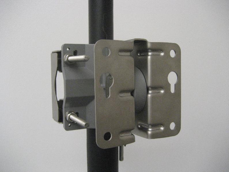
10 Tilting Screws Figure 2-9 Antenna Mounted on Pole 3. A8n and A8in Base Station Mounting Mounting for A8n and A8in are the same. Figure 10 shows the back view of A8in. A8n has the same mounting screw.

11 Figure 3-1 Back-View of A8in 3.1. A8n and A8in Base Station Mounting Kit A B C D Mounting back plate Main mounting module 4x mounting screws and nuts 4x locking screws and nuts

. 3. The mounting kit must be installed with the key hole pointing direction (Figure 3-5). 4.")
12 Figure 3-2 A8n and A8in Base Station Package 3.2. Mounting A8n and A8in on Pole 1. Assemble the mounting kit according to Figure 3-3 with one side of the screw installed. 2. Mount the kit to the pole at the desired height and tighten all 4 screws to fix its position (Figure 3-4). 3. The mounting kit must be installed with the key hole pointing direction (Figure 3-5). 4. Clamp the unit to the mounting kit, as shown in Figure 3-6 and make sure the mounting screw is locked in the key hole. 5. Screw in 4 locking screw to secure A8in with the mounting kit (Figure 3-6). 6. The mounting kit will fit with pole diameter from 1 inch to 3 inches. Figure 3-3 Mounting kit assembly


13 Figure 3-4 Completion of Mounting Kit Figure 3-5 mounting screw locking direction Figure 3-6 Clamping and secure the unit on pole

14 4. Mounting A8n 2.4GHz antenna and cable connection 4.1. Introduction 1. The A8n AP has 4 external 2.4GHz panel antennas. The A8Ein and A8in has internal 2.4GHz antenna. External 2.4GHz panel antenna gives you more freedom to adjust the direction and tilting of each antenna. Internal 2.4GHz antenna is easier for installation. 2. At the top of A8n, there are 8 N-female RF connector marked with 1-8. They are grouped to 4 groups to connect to 4 external 2.4GHz panel antenna. 3. It is recommended to seal the A8n series RF ports with weatherproof materials to prevent water leakage. Figure 4-1 Top of A8n 8 N-female RF port for external 2.4GHz panel antenna connection 4.2. Mounting of A8n 2.4GHz Panel antenna Mount the 2.4GHz radio antenna to the pole. It is recommended that to install the standard A8n 2.4GHz antenna with the RF ports facing downward, as shown in Figure 4-2. Adjust the direction and down-tilt angle of the A8n 2.4GHz antenna to align, as shown in Figure 4-3


15 Figure 4-2 Standard A8n 2.4GHz Antenna Figure 4-3 Adjust A8n 2.4GHz Antenna tilting 4.3. Cable connection from A8n to 2.4GHz panel antenna Connect RF cable from panel antenna port to A8n 2.4GHz RF port at the top of A8n. RF port 1 and 2 of A8n must connect to the same panel antenna. The same for ports (3.4), (5,6) and (7.8) which each pairs must connect to the same panel antenna. It is recommended to connect the A8n port to antenna port according Figure 4-5 mapping. It is recommended to seal the A8n series 2.4GHz antenna RF ports with weatherproof materials to get the best performance according to the procedure in chapter 6 of this document


16 Figure 4-4 RF cable connection from panel antenna Figure 4-5 Antenna port to A8n port mapping


17 Figure 4-6 A8n 2.4GHz RF port groups 5. RF Cables Connection and Mounting of 5GHz Radio Antenna 1. The standard A8n series 5GHz antenna has two RF ports. 2. Connect RF cables from the A8n series 5GHz antenna RF ports which marked a0 and a1 next to the RF ports. 3. It is recommended to seal the A8n series 5GHz antenna RF ports with weatherproof materials to get the best performance according to the procedure in chapter 6 of this document Figure 5-1 5GHz a0 & a1 antenna RF ports


18 Figure dBi 5GHz Antenna mounting Figure 5-2 Waterproof wrapping direction 6. Weatherproofing A8n Series Radio Antenna 6.1. Introduction Sealing materials are applied to outdoor antenna connectors to accomplish several goals. First and foremost is to prevent water from entering the connector. The second reason is to protect the connector from gradual degradation due to UV radiation and pollution. Sunlight and weather will oxidize metal surfaces and cause DC resistance to increase on exposed mating surfaces. It is true that the RF cable connectors are supposed to be weatherproof, but if left exposed to weather conditions, they will tarnish and start to look rather ugly in a short time. A good taping job will also prevent the RF cable connectors from loosening up, which is a common occurrence for RF cables exposed to vibration and strong winds. We recommend the following sealing materials for weatherproofing the antenna connectors: 1. High-quality, all-weather, black plastic electrical tape, preferably 3/4 (19mm) wide to make it easier to manipulate the tape around the A8n Series BTS radio antenna ports. An RF port is often first wrapped with a layer of electrical tape to make it easier to remove the butyl rubber layer. In addition, one or more layers of
 wide to make it easier to manipulate the tape around the A8n series BTS radio antenna ports.")

19 electrical tape are used as a final outer wrap to provide UV protection. We recommend the 3M Scotch Super 88 Vinyl Electrical Tape for this purpose. 2. High-quality, all-weather, black butyl rubber tape, preferably 3/4 (19mm) wide to make it easier to manipulate the tape around the A8n series BTS radio antenna ports. Butyl rubber tape is self-amalgamating - it chemically bonds to itself, forming a strong, waterproof joint. A layer of butyl rubber tape is applied around a connector joint to provide a weatherproof seal, often on top of a layer of electrical tape. We recommend the Andrew Corporation butyl rubber tape for this purpose. Figure 6-2 Andrew Corporation Butyl Rubber Tape Figure 6-1 3M Scotch Super 88 Vinyl Electrical Tape Installation Tips A few general rules about weatherproofing RF ports: 1. Always apply tape at temperature above 32 degrees F to ensure adhesion. When working in cold weather, always protect your tape rolls by storing it under your coat and next to your body to keep tape flexible. If the tape cannot stretch elastically, it will not seal properly. 2. Do not stretch the tape to the point where it distorts. Only apply enough pressure to get a smooth wrap. 3. Smooth each wrapped layer of tape with your hands to ensure proper adhesion. 4. Do not pull the tape to tear it - always cut the tape. A pulled tape will most likely unravel, decreasing protection.

20 5. In warm climates where there will be long exposure to sunlight, it is a good idea to wrap an extra layer or two of electrical plastic tape over the butyl rubber layer to enhance UV protection. 6. For vertical runs of cable, the final layer of electrical tape should be wrapped from the bottom to the top, and overlap about 50% of the width of the tape. This will provide the same effect as shingles on a house. The water will run down across the joints without going into the joints. In order to properly weatherproof of the BTS radio antenna ports, they must be prepared before the installation. 1. Cut the butyl rubber tape into 1/5 (5mm) by 4 (100mm) strips. 2. Wrap a strip of butyl rubber tape around the base of each antenna port in the clockwise direction. Take extra care to make sure that the resulting butyl rubber ring would not hinder the tightening of the RF cable connector around the antenna port. Figure 6-3 Wrap the Butyl Rubber Strip

21 Figure 6-4 Butyl Rubber Ring Finished 6.2. Connecting RF Cables 1. Make sure each RF cable and its connectors are absolutely dry. 2. Loosely connect all the RF cables from each RF port. Do not tighten up any of the connections. 3. Secure the RF cable bundles to the pole. 4. Tighten the RF cable connectors around the A8n series 5GHz antenna ports with a torque wrench to the proper torque limit to ensure that correct internal seals and surface contacts are made. If a torque wrench is not available, first tighten the connector to finger tight, then tighten it with a wrench for an additional ⅛ to ¼ turn from the finger tight position. 5. Weatherproof the A8n series antenna ports Weatherproofing on A8n 2.4GHz Radio Antenna Ports 1. Start wrapping a layer of electrical tape from 1/4 (6mm) above the edge of the RF cable connector. Overlap the tape to half width. The tape should cover the RF cable connector body, and extend 1 (25mm) above the cable connector clamping nut. The tape can be applied in one or more strips if necessary. A strip can be coiled onto an applicator such as a pencil. Apply only enough tension to get good adhesion and keep the tape smooth.
 above the electrical tape and cut the tape.")

22 Extend 1 (25mm) Figure 6-5 Wrapping direction and extends the wrap 1 above the connector clamping 2. Start wrapping a layer of butyl rubber tape from the base of the A8n series 5GHz antenna port. Overlap the tape to half width. Finish the wrap at 1 (25mm) above the electrical tape and cut the tape. Take extra care to make sure that the RF cable connector to A8n series 5GHz antenna port junction is tightly sealed. Press the tape edges together so that there are no gaps. Press the tape against the RF cable connector body and the A8n series 5GHz antenna port. 3. If enhanced UV protection is required, start wrapping a layer of electrical tape from the base of the A8n 2.4GHz antenna port. Overlap the tape to half width. Finish the wrap at 1 (25mm) above the butyl rubber tape and cut the tape Weatherproofing A8n series 5GHz Antenna RF Ports 1. Start wrapping a layer of electrical tape from 1/4 (6mm) above the edge of the RF cable connector. Overlap the tape to half width. The tape should cover the RF cable connector body, and extend 1 (25mm) above the cable connector clamping nut. The tape can be applied in one or more strips if necessary. A strip can be coiled onto an applicator such as a pencil. Apply only enough tension to get good adhesion and keep the tape smooth. 2. Start wrapping a layer of butyl rubber tape 1 (25mm) below the electrical tape. Overlap the tape to half width. Finish the wrap at the base of the antenna port and cut the tape. Take extra care to make sure that the RF cable connector to A8n series 5GHz antenna RF port junction is tightly sealed. Press the tape edges together so that there are no gaps. Press the tape against the RF cable connector body and the A8n series 5GHz antenna RF port.
23 3. Start wrapping a layer of electrical tape 1 (25mm) below the butyl rubber tape, overlapping at half-width. Finish the wrap at the base of the A8n series 5GHz antenna RF port and cut the tape. Repeat this process for a second layer, and if enhanced UV protection is required, a third layer. 7. Recommendation on Installation Pole 7.1. Antenna Pole Height and Size The antenna should be mounted at least 1 meter above any obstacle in front. Hence, the height of the pole depends on the situation. In the situation shown below, the pole should be at least 2 to 3 meters to avoid any obstacle. The mounting kit can mount the pole with diameter from 1.5 inches to 3 inches. Remark: 2 inches pole is recommended as it can install A2 and 5GHz 20dBi panel antenna in the same pole also. Figure 7-1 At Least 1m above Any Obstacle in Front 7.2. Grounding Protection

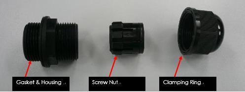
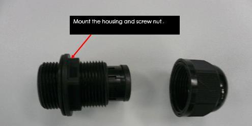
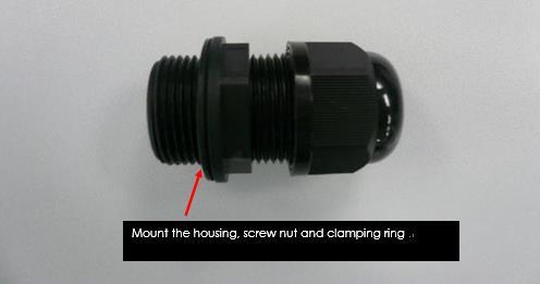
24 The A8n series must be properly connected to earth ground. Failure to do so may result in equipment damage, injury or death. Product warranty does not cover damage resulting in part or in whole from improper grounding. An external grounding wire must be installed, especially when A8-Ein is deployed on a non-metal pole or the metal pole is not properly grounded. Please consult your location s building and electrical codes and follow them, or consult standards such as National Electric Code. The grounding screw is located at the bottom of A8n series as showed in figure 30. Use 10 AWG wire with corrosion-resistant connectors for connecting to one or more approved grounding rods or building s earthling network. Earth-to-ground resistance should not be more than 10ohms. 1. Loose the grounding screw of A8n series. 2. Attach a length 10 AWG bare copper with a terminal connector to the grounding screw. 3. Tighten the screw nut. 4. Connect the other end of grounding wire to grounding rods or earth ground. Figure 7-2 Grounding Screw 8. Ethernet Connector Packet Installation The Ethernet connector packet includes the following components: 1. Gasket 2. Housing 3. Screw Nut 4. Clamping Ring
25


26 Cat 5e or cat 6 Ethernet cable are recommended. Maximum cable length between PoE adapter and A8n is 100m. The end of cable, RJ-45 modular jack pins are numbered 1 through 8 as shown:
27 The assignments of wire pairs to plug and jack pins are as follows: A8n Series Super WiFi Base Station Installation Guide Pin Pair wire Color 1 2 white / orange 2 2 orange 3 3 white / green 4 1 blue 5 1 white / blue 6 3 green 7 4 white / brown 8 4 brown Table 8-1 Assignments of wire pairs 9. Lightning Protection

28 Table 9-1 Lightning Protection System for Pole Mounting A8n Series Base Station A lightning protection system provides a means by which a lightning discharge may enter or leave earth without passing through and damaging personnel, equipment or the buildings. It does not prevent lightning from striking but provides a means for controlling it and prevents damage by providing a low resistance path for discharge of the lightning energy. A typical lightning protection system for A8n series base station is shown in Figure 24. It consists of 5 parts: Lightning Rod Ground Conductor Grounding Plate Earth Termination
29 External Lightning Protectors 1) Lightning Rod A lightning rod (air terminal) neutralizes the downward lightning strike by launching an upward ionized path. The lightning current will follow this path and is thus diverted away from personnel and electronic equipment. The lightning rod must be constructed of steel with a pointed tip and welded to a ground conductor. The lightning rod must be installed at top of the mounting post or tower higher than the highest portion of equipment it protects. For A8n base station installation, the 4- sector antennas are usually the highest points and usually protrude away from the post. Suppose the horizontal distance from the post to the top outer most point of antenna is d, the minimum height of the tip of lightning rod above the highest point of antenna (H) is recommended to be at least 2d such that a cone of protection of 60 degree is ensured around the pole or tower. In areas of high lightning activities, the height H should be increased to 5d. 2) Ground Conductor A ground conductor is a metal strip or rod usually made of copper or similar conductive metal linking the lightning rod to the earth. The prime purpose of the ground conductor is to conduct lightning current from the lightning rod to the earth termination. It also provides connection to a metal grounding plate so that the equipment under protection can be connected to at the shortest distance possible. A ground conductor must be installed straight and vertical without bends such that it connects to the earth termination at the shortest and direct path. As a rule of thumb, a minimum 50 mm 2 in cross sectional area or AWG 0 copper conductor is recommended for the ground conductor. Aluminum or iron conductor can also be used but with poorer conductivity. Minimum cross sectional area of copper, aluminum and iron ground conductor are 16, 25 and 30 mm 2 respectively. The connection between the ground conductor and the earth must be no higher than 5 ohms. This is achieved by grounding to special grounding bars in the case of post mounting or to the steel reinforcement bars at the concrete base of the tower in case of tower mounting. 3) Grounding Plate A grounding plate is a metal plate welded to the post or tower which provides a common grounding connection placed at a short distance from the equipment and
30 ground conductor. The grounding plate is connected to the ground conductor using a ground cable and clamp. The A8n series base station grounding terminal is located at the bottom of chassis compartment. This grounding terminal should be connected to the grounding plate using a ground cable and lug. AWG 10 (around 5 mm 2 cross-sectional area) copper wire is recommended for the ground cable. Only one grounding connection to the pole or tower is allowed. All antenna ports of A8n base station are grounded internally. For shielded Ethernet cable (AC model) or shielded POE cable (DC model) grounding, the ground wire of the Ethernet/ POE cable should be connected to the screw port located at the inside bottom of lower chassis compartment of A8n series base station. The other side of the Ethernet/ POE cable will be connected to indoor units via a grounded external lightning protector box. The external lightning protector box should be located outside the building as near as practicable to the entrance of the cables to the building and it is connected to an earth termination via a ground cable. 4) Earth Termination An earth termination is a metal grounding bar which is planted into the earth for conducting and dispersing lightning current from the ground conductor to earth. The ground conductor is connected to this grounding bar at one end. The mounting post or tower should have its own grounding bar. The size of metal grounding bar should be designed such that the total resistance from the lightning rod to the earth termination is less than 5 ohms. 5) External Lightning Protectors Lightning protector (or surge arrestor) is a component which provides a lower resistance path to conduct sufficient charge from the surge in order to lower the surge voltage to a safe level. External lightning protectors can be used to provide additional protection to the Altai A8n series base station embedded protectors. They can be put at strategic points such as the Ethernet port, AC power or antenna ports close to the A8n series base station. External lightning protectors are available in the market in the form of a protector box, which can be inserted simply in front of the ports to be protected. As the magnitude and speed of lightning varies in different places, the specifications of external lightning protectors should be chosen appropriately according to local protection requirements.
31 While this section gives a general guideline on lightning protection, the detail specifications of a lightning protection system must be provided by local electricians and must be maintained and checked periodically in accordance with local regulations. Altai does not provide any warranties as to the effectiveness of the suggested measures. The implementation of the suggested measures is at the customer s own discretion. Under no circumstances will Altai be liable for any consequences resulting from the implementation or lack of implementation of the suggested measures.
Copyright Black Box Corporation. All rights reserved.
 Copyright 2004. Black Box Corporation. All rights reserved. 1000 Park Drive Lawrence, PA 15055-1018 724-746-5500 Fax 724-746-0746 JULY 2004 LW6200A LW6201A Pure Networking 2.4-GHz Antennas CUSTOMER SUPPORT
Quick Start Guide. Version: 1.0 F/W: V1.2.0_RC1b. Date: December 11, 2017
 VigorAP 920R Series Ruggedized Outdoor AP with Extreme 802.11ac Power Warranty Quick Start Guide Version: 1.0 F/W: V1.2.0_RC1b Date: December 11, 2017 We warrant to the original end user (purchaser) that
DOCUMENT TR2028/R3- PICO BASE STATION WITH GPS SYNC
 19473 Fraser Way,Pitt Meadows, B.C. Canada V3Y 2V4 Phone (604) 460-6002 Fax (604) 460-6005 www.tranzeo.com DOCUMENT TR2028/R3- PICO BASE STATION WITH GPS SYNC HARDWARE INSTALLATION GUIDE Thank you for
System Requirements: D-Link Systems, Inc.
 System Requirements: Minimum System Requirements: CD-ROM Drive Computers with Windows, Macintosh, or Linux-based operating systems Installed Ether net Adapter Internet Explorer version 6.0 or Netscape
ScreenLogic Wireless Connection Kit. Installation Guide. pool/spa control system
 pool/spa control system ScreenLogic Wireless Connection Kit Installation Guide P/N 520663 - Rev A 8 Technical Support Contact Technical Support at: Sanford, North Carolina (8 A.M. to 5 P.M.) Phone: (800)
S5-ADU. Front... 4 Rear... 4
 Trantec ANTENNA DISTRIBUTOR INSTRUCTION MANUAL S5-ADU Thank you for purchasing TRANTEC Antenna Distributor. Please carefully follow the instructions in this manual to ensure long, trouble-free use of your
Installation & Weatherproofing Guide for ENCOM Broadband Radios
 Installation & Weatherproofing Guide for ENCOM Broadband Radios Read the following instructions before proceeding with your ENCOM Wireless Radio installation. Keep these instructions in safe location for
ORiNOCO AP-4000MR-LR and AP-4900MR-LR Access Points Safety and Regulatory Compliance Information
 IMPORTANT! Visit http://support.proxim.com for the latest safety and regulatory compliance information for this product. ORiNOCO AP-4000MR-LR and AP-4900MR-LR Access Points Safety and Regulatory Compliance
Cisco Aironet 2.4-GHz/5-GHz 8-dBi Directional Antenna (AIR-ANT2588P3M-N)
") Cisco Aironet.4-GHz/5-GHz 8-dBi Directional Antenna (AIR-ANT588P3M-N) This document outlines the specifications for the Cisco Aironet AIR-ANT588P3M-N.4/5-GHz 8-dBi 3-Port Directional Antenna with N-connectors
Cisco Aironet.4-GHz/5-GHz 8-dBi Directional Antenna (AIR-ANT588P3M-N) This document outlines the specifications for the Cisco Aironet AIR-ANT588P3M-N.4/5-GHz 8-dBi 3-Port Directional Antenna with N-connectors
Table of Contents. Mounting Diagram.. Wiring Information.. Setting the STR 1000 as a Repeater or a Transmitter. STR 1000 Frequently Asked Questions..
 STR 1000 Series Repeater Installation Manual (V 3.0) Table of Contents MOUNTING Mounting Diagram.. Page 2 WIRING INFORMATION Wiring Information.. Page 3 Setting the STR 1000 as a Repeater or a Transmitter.
CRUX II/BTGPS USER GUIDE. Model:D1598
 CRUX II/BTGPS USER GUIDE Model:D1598 0 Federal Communication Commission Interference Statement This equipment has been tested and found to comply with the limits for a Class B digital device, pursuant
ANT400 OPTIONAL REMOTE ANTENNA MODULE
 P516-099 ANT400 OPTIONAL REMOTE ANTENNA MODULE INSTRUCTIONS FOR ANT400-REM-I/O, ANT400-REM-I/O+6dB, ANT400-REM-CEILING, ANT400-REM-HALL Para el idioma español, navegue hacia www.schlage.com/support. Pour
Remote Control Outlets Operating Instructions
 Remote Control Outlets Operating Instructions - FOR INDOOR OR OUTDOOR USE - IMPORTANT SAFEGUARDS Signal Word Definitions NOTE: These are general definitions only; all may not pertain to the actual product
Lightning Strikes. Presented to the Greater Norwalk Amateur Radio Corporation Inc. February 8, 2017 Steven M. Simons W1SMS
 Lightning Strikes Presented to the Greater Norwalk Amateur Radio Corporation Inc. February 8, 2017 Steven M. Simons W1SMS ARRL CT State Technical Coordinator The Power of Lightning What is a Ground? Design
On-Line Cardio Theater Wireless Digital Transmitter Installation and Instruction Manual
 On-Line Cardio Theater Wireless Digital Transmitter Installation and Instruction Manual Full installation instructions accompany your Cardio Theater equipment order. This On-Line version of our Installation/Instruction
HP ProCurve 6.9/7.7dBi Dual Band Directional Antenna (J8999A) Guide
 Guide") HP ProCurve 6.9/7.7dBi Dual Band Directional Antenna (J8999A) Guide SAFETY The HP ProCurve J8999A and all associated equipment should be installed in accordance with applicable local and national electrical
HP ProCurve 6.9/7.7dBi Dual Band Directional Antenna (J8999A) Guide SAFETY The HP ProCurve J8999A and all associated equipment should be installed in accordance with applicable local and national electrical
TM14-2.4G/R6014FS/R608FS Radio Control Instruction Manual
 TM14-2.4G/R6014FS/R608FS Radio Control Instruction Manual INTRODUCTION Thank you for purchasing a FutabaR digital proportional R/C system. In order for you to make the best use of your system and to use
Installation and Operation Manual MSI. Multi-Sensor Interface Hub. Interface Module for all Sensors Network and Wireless CAUTION
 Installation and Operation Manual MSI Multi-Sensor Interface Hub Interface Module for all Sensors Network and Wireless CAUTION This equipment complies with the limits for a Class B digital device, pursuant
12V Victor 888 User Manual
 The Victor speed controllers are specifically engineered for robotic applications. The high current capacity, low voltage drop, and peak surge capacity make the Victor ideal for drive systems while its
INSTALLATION INSTRUCTIONS FOR THE CLIKCARD COMMERCIAL RECEIVER (NARROW BAND)
") Doc. 6001200 Rev. B INSTALLATION INSTRUCTIONS FOR THE CLIKCARD COMMERCIAL RECEIVER (NARROW BAND) TABLE OF CONTENTS TABLE OF CONTENTS...1 INSTALLATION FOR INFINITY AND PROCARD...3 PULLING CABLE... 3 MOUNTING
Doc. 6001200 Rev. B INSTALLATION INSTRUCTIONS FOR THE CLIKCARD COMMERCIAL RECEIVER (NARROW BAND) TABLE OF CONTENTS TABLE OF CONTENTS...1 INSTALLATION FOR INFINITY AND PROCARD...3 PULLING CABLE... 3 MOUNTING
Hughes 9450 Mobile Satellite Terminal. Installation Guide
 Hughes 9450 Mobile Satellite Terminal Installation Guide 3004129 Revision A September 15, 2010 Copyright 2010 Hughes Network Systems, LLC All rights reserved. This publication and its contents are proprietary
Cisco Aironet 13.5-dBi Yagi Mast Mount Antenna (AIR-ANT1949)
") Cisco Aironet 13.5-dBi Yagi Mast Mount Antenna (AIR-ANT1949) Overview This document describes the 13.5-dBi Yagi mast mount antenna and provides instructions for mounting it. The antenna operates in the
Cisco Aironet 13.5-dBi Yagi Mast Mount Antenna (AIR-ANT1949) Overview This document describes the 13.5-dBi Yagi mast mount antenna and provides instructions for mounting it. The antenna operates in the
Yagi and Omni Antennas Installation Manual
 Yagi and Omni Antennas Installation Manual 25500445 Rev. A0 0218 Printed in U.S.A. Copyright 2018 Federal Signal Corporation Limited Warranty This product is subject to and covered by a limited warranty,
Installation & Operating Manual. iwap202
 Installation & Operating Manual iwap202 This page is intentionally left blank. Document Number 409345 (based on 407655) (See Last Page for Revision Details) For warranty information, refer to Terms and
Instruction Manual. for Media Monkey. 1
 TM TM Instruction Manual for Media Monkey www.audioaperemote.com 1 Congratulations on acquiring your fine Audio Ape product Let s dive right in, getting up and running is a snap. Here are the components:
User's Manual F10G-5S-LCD 1 / 20 BOOST CELL PHONE SIGNAL BOOSTERS MADE BY HUAPTEC
 User's Manual F10G-5S-LCD 1 / 20 BOOST CELL PHONE SIGNAL BOOSTERS MADE BY HUAPTEC Table of contents WHAT IS INCLUDED... 3 1 HOW IT WORKS... 3 2 TOOL REQUIRED... 3 3 HOW TO INSTALL YOUR NEW CELLULAR BOOSTER...
LJ element beam for 10 or 12 meters INSTRUCTION MANUAL. CAUTION: Read All Instructions Before Operating Equipment
 LJ-113 3 element beam for 10 or 1 meters INSTRUCTION MANUAL CAUTION: Read All Instructions Before Operating Equipment 308 Industrial Park Road Starkville, MS 39759 USA Tel: 66-33-9538 Fax: 66-33-6551 VERSION
P700-WLS ioprox Receiver
 Installation Manual DN1628-1611 Pre-Installation Notes Copyright 2016 Tyco International Ltd. and its Respective Companies. All Rights Reserved. All specifications were current as of publication date and
Ambient Weather WS-0270 Wireless Indoor / Outdoor Thermometer with Indoor Humidity User Manual
 Ambient Weather WS-0270 Wireless Indoor / Outdoor Thermometer with Indoor Humidity User Manual Table of Contents 1 Introduction... 1 2 Getting Started... 1 2.1 Parts List... 2 2.2 Recommend Tools... 2
IS76 Beacon with Ferrite Antenna Installation Manual
 IS76 Beacon with Ferrite Antenna Installation Manual Edition: June 2016 Document N : F.01U.136.807 V3 Page 1 of 10 Document No F.01U.136.807 V3 IS76 Beacon with Ferrite Antenna: Installation Manual Edition:
WLS-5500 Receiver (KSF & W26)
") WLS-5500 Receiver (KSF & W26) Installation Manual DN1869-0912 Warning! This manual contains information on limitations regarding product use and function and information on the limitations as to liability
WLS-5500 Receiver (KSF & W26) Installation Manual DN1869-0912 Warning! This manual contains information on limitations regarding product use and function and information on the limitations as to liability
P700WLS IoProx Receiver
 Installation Manual Warning! This manual contains information on limitations regarding product use and function and information on the limitations as to liability of the manufacturer. The entire manual
USER MANUAL Digital Wireless Gateway U9120-W4 (P/N: 44002G-01)
") USER MANUAL Digital Wireless Gateway U9120-W4 (P/N: 44002G-01) 19549P-82 (11-16) 2016 DAVID CLARK COMPANY INCORPORATED Cautions and Warnings READ AND SAVE THESE INSTRUCTIONS. Follow the instructions in
USER MANUAL Digital Wireless Gateway U9120-W4 (P/N: 44002G-01) 19549P-82 (11-16) 2016 DAVID CLARK COMPANY INCORPORATED Cautions and Warnings READ AND SAVE THESE INSTRUCTIONS. Follow the instructions in
INSTALLATION AND OPERATING MANUAL
 INSTALLATION AND OPERATING MANUAL FOR RBDA-PCS-1/25W-90-A INDOOR REPEATER TABLE OF CONTENTS PARAGRAPH PAGE NO BDA OVERVIEW 3 BDA BLOCK DIAGRAM DESCRIPTION 3 FCC INFORMATION FOR USER 3 BDA BLOCK DIAGRAM
87.5 TO MHz BAND II 2 WAY 4.8dBi STACKED DIPOLE ANTENNA
 87.5 TO 108.0 MHz BAND II 2 WAY 4.8dBi STACKED DIPOLE ANTENNA 1. INTRODUCTION 3 1.1. GENERAL INFORMATION 3 1.2. UNPACKING AND CHECKING 3 1.3. WARRANTY 3 1.4. USER SAFETY RESPONSIBILITY 4 1.5. INSTALLATION
PAC-12 Kit Contents. Tools Needed Soldering iron Phillips screwdriver Wire stripper Wrenches, 7/16 and 1/2 Terminal crimp tool Pliers Solder
 PAC-2 Kit Contents Part Quantity Screws: 8/32 x 3/8 Screws: 8-32 x 5/6 Screw: 8-32 x /4 #8 internal tooth washers #8 solder lug ring terminals Bolt: Aluminum, /4-20 x.5 /4 internal tooth washer Nut: Aluminum
Spiderbeam Balun Construction Guide
 BALUN CONSTRUCTION GUIDE Ver. 1.0 1 The components of the Balun Kit are in a plastic bag. Most of the components are inside the plastic case of the balun. The aluminum U-profile and the RG-142 Teflon Coax
Manual Unihan UPWL6025
 Manual Unihan UPWL6025 Federal Communications Commission Statement This device complies with FCC Rules Part 15. Operation is subject to the following i. This device may not cause harmful interference,
MFJ-1750/1752 2M BASE ANTENNA with 5/8 GROUND PLANE Instruction Manual
 MFJ-1750/1752 2M BASE ANTENNA with 5/8 GROUND PLANE Thank you for purchasing the MFJ-1750/1752. The 1750 is a 5/8 wave antenna designed for operation on 144-148 MHz. The 1752 is designed to operate on
USER MANUAL MODEL: BM-162
 USER MANUAL MODEL: BM-162 Parents Unit: A. Name Power ON/OFF Key Music Key PTT Key Volume - Key Microphone Power & Low battery indicator LCD display Volume + Key Night Light and torch Key Speaker -Belt
IS76 Beacon with Ferrite Antenna Installation Manual
 IS76 Beacon with Ferrite Antenna Installation Manual V2 F.01U.278.518 2013.10 Document # F.01U.278.518 V2 IS76 Beacon with Ferrite Antenna: Installation Manual Edition: October 2013 Author: TeleAlarm TeleAlarm
METAL DETECTOR INSTRUCTION GUIDE
 METAL DETECTOR INSTRUCTION GUIDE SET UP STEP 1. STEP 2. Your NATIONAL GEOGRAPHIC detector requires no assembly or tools. Simply remove the detector from the box. Press down the red UNLOCK button on both
Instruction manual ADN-W AM. Antenna Module
 Instruction manual ADN-W AM Antenna Module For your safety www www.sennheiser.com Manual Contents For your safety... 1 The ADN-W AM antenna module... 1 Package contents... 2 Components required for wireless
Radio Link Starter Kit
 Radio Link Starter Kit Installation Manual BARTLETT Instrument Co. 1032 Avenue H Fort Madison, IA 52627 319-372-8366 www.bartinst.com Table of Contents Radio Link Starter Kit Manual... 3 System Requirements...
User Manual. Product Name:tablet Model Name:TM800A740M Brand Name:NuVision. Manufacture:Shenzhen Vastking Electronic Co.,LTD.
 User Manual Product Name:tablet Model Name:TM800A740M Brand Name:NuVision Manufacture:Shenzhen Vastking Electronic Co.,LTD. FCC Warning This device complies with part 15 of the FCC
Wireless TFT LCD Monitor
 Wireless TFT LCD Monitor Description Screen Ratio: 16 : 9 Resolution: 800*RGB*480 TV: PAL / NTCS Voltage: 10--28V Rated Capacity: 5W Brightness: 450cd/m2 Contrast: 450:1 Operate temperature: -20~65 Display
Ambient Weather F007TP 8-Channel Wireless Probe Thermometer User Manual
 Ambient Weather F007TP 8-Channel Wireless Probe Thermometer User Manual Table of Contents 1 Introduction... 2 2 Getting Started... 2 2.1 Parts List... 2 2.2 Probe Thermometer Sensor Set Up... 2 3 Remote
HotPoint TM. Hardware Installation Guide HotPoint 5200 Access Point. Published March 2014 (Revised 2016)
") HotPoint TM Hardware Installation Guide HotPoint 5200 Access Point Published March 2014 (Revised 2016) 2016 Firetide, Inc. All rights reserved. Firetide, the Firetide logo, Reliable connectivity anywhere,
HotPoint TM Hardware Installation Guide HotPoint 5200 Access Point Published March 2014 (Revised 2016) 2016 Firetide, Inc. All rights reserved. Firetide, the Firetide logo, Reliable connectivity anywhere,
INSTALLATION MANUAL PBL-UMP
 INSTALLATION MANUAL PBL-UMP Table of Contents Warning Statements... 4 Parts List... 5 Installation Tools... 5 Features... 7 Projector Preparation... 8 Bracket Installation... 10 Leveling the Mounting Bracket...
CCR24T CCR24R. User s Guide WIRELESS TRANSMITTER SYSTEM WARRANTY SERVICE CARD WARRANTY CARD
 WARRANTY SERVICE CARD WARRANTY CARD PRODUCT NAME Wireless Transceiver System PERIOD MODEL NAME CCR24GEN YEAR PURCHASE DATE.. 200_ From the date of WARRANTY PERIOD.. 200_ purchase. CUSTOMER S ADDRESS :
INSTALLATION MANUAL PBC-UMS
 INSTALLATION MANUAL. PBC-UMS Premier Mounts 3130 E. Miraloma Avenue Anaheim, CA 92806 Phone: (800) 368-9700 Fax: (800) 832-4888 mounts@mounts.com www.mounts.com Rev. 01 PBL-110 Projector Mount Page 2 Installation
Active Transmitter Combiner 8:1 AC 3200-II. Instruction manual
 Active Transmitter Combiner 8:1 AC 3200-II Instruction manual Contents Contents Important safety instructions... 2 The AC 3200-II active transmitter combiner 8:1... 4 Delivery includes... 4 Connection
Radio Link Starter Kit
 Radio Link Starter Kit Installation Manual BARTLETT Instrument Co. 1032 Avenue H Fort Madison, IA 52627 319-372-8366 www.bartinst.com Table of Contents Radio Link Starter Kit Manual... 3 System Requirements...
WS-7220U-IT 915 MHz Wireless Weather Station. Instruction Manual
 WS-7220U-IT 915 MHz Wireless Weather Station Instruction Manual 1 TABLE OF CONTENTS Introduction..3 Inventory of Contents 4 Quick Set Up 4 Detailed Set Up 4-5 Battery Installation....4-5 12 or 24 Hour
Quick Start Guide. Antenna Alignment Tool AIMWLLR0-35. QSG rev 7 AIMWLLR0-35 [NRB-0200] QSG.indd 1
![Quick Start Guide. Antenna Alignment Tool AIMWLLR0-35. QSG rev 7 AIMWLLR0-35 [NRB-0200] QSG.indd 1](/thumbs/86/94268876.jpg "Quick Start Guide. Antenna Alignment Tool AIMWLLR0-35. QSG rev 7 AIMWLLR0-35 [NRB-0200] QSG.indd 1") Quick Start Guide Antenna Alignment Tool AIMWLLR0-35 QSG-00097 rev 7 AIMWLLR0-35 [NRB-0200] QSG.indd 1 Welcome This quick start guide is designed to familiarize you with the features and use of the NetComm
Quick Start Guide Antenna Alignment Tool AIMWLLR0-35 QSG-00097 rev 7 AIMWLLR0-35 [NRB-0200] QSG.indd 1 Welcome This quick start guide is designed to familiarize you with the features and use of the NetComm
OMEGA. Communications Interface Cabinet. Antenna Installation Manual
 Ω OMEGA Communications Interface Cabinet Antenna Installation Manual 0049-0706-004 The products and programs described in this User s Guide are licensed products of Telenetics Corporation. This User s
SP GHz Digital Wireless Speakers. User s Manual. Please read before using the equipment. Please visit for details.
 SP1390 2.4GHz Digital Wireless Speakers User s Manual Please read before using the equipment. Please visit www.promowide.com for details. INTRODUCTION This 2.4G digital wireless speakers system uses latest
Ambient Weather WS-40 Wireless Indoor / Outdoor Thermometer
 Ambient Weather WS-40 Wireless Indoor / Outdoor Thermometer Table of Contents 1. Introduction... 1 2. Getting Started... 1 2.1 Parts List... 1 2.2 Thermometer Sensor Set Up... 1 2.3 Display Console Set
BT11 Hardware Installation Guide
 Overview The Mist BT11 delivers a BLE Array AP with internal antennas that are used for BLE based location. 1 Understanding the Product Included in the box: BT11 Mounting bracket with mounting hardware
Hughes 9450 Mobile Satellite Terminal Series. Installation Guide
 Hughes 9450 Mobile Satellite Terminal Series Installation Guide Document No. 3004129-0001 Revision E 17 November 2017 Copyright 2013, 2017 Hughes Network Systems, LLC All rights reserved. This publication
Hughes 9450 Mobile Satellite Terminal
 Hughes 9450 Mobile Satellite Terminal Installation Guide 3004129-0001 Revision C Copyright 2011 Hughes Network Systems, LLC All rights reserved. This publication and its contents are proprietary to Hughes
Circularly Polarized FM Broadcast Antenna
 Circularly Polarized FM Broadcast Antenna Versa2une (SLV) 6 to 12-bay, full-wave-spaced Instruction Manual Installation, Operation, & Maintenance Congratulations! Thank you for purchasing one of the finest
ELETICS ZipLine 58 (& ZipLine 2) Quickstart Installation Manual
 Quickstart Installation Manual") ELETICS ZipLine 58 (& ZipLine 2) Quickstart Installation Manual Version 2.13 September 9 2013 www.teletics.com 1 Statement of Conformity Note: This equipment has been tested and found to comply with the
ELETICS ZipLine 58 (& ZipLine 2) Quickstart Installation Manual Version 2.13 September 9 2013 www.teletics.com 1 Statement of Conformity Note: This equipment has been tested and found to comply with the
SecureMesh Repeater (RPTR-3000)
") INSTALLATION GUIDE SecureMesh Repeater (RPTR-3000) Contents Introduction... 3 SecureMesh Repeater Components... 4 Accessories... 5 Preparing for Installation... 10 Installation Location... 10 Preparation
INSTALLATION GUIDE SecureMesh Repeater (RPTR-3000) Contents Introduction... 3 SecureMesh Repeater Components... 4 Accessories... 5 Preparing for Installation... 10 Installation Location... 10 Preparation
FOR AVLEX ONLY MT-24A. User Guide. 2.4 GHz Digital Stationary Transmitter
 2.4 GHz Digital Stationary Transmitter User Guide All rights reserved. MN 017/05 Do not copy or forward without prior approvals MIPRO. Specifications and design subject to change without notice. 2 CE5
BRU-100 Physical Installation
 APPENDIX B BRU-100 In This Appendix: Warnings and Cautions, page 50, page 51 Check List, page 57 This appendix provides guidance for the physical installation of the BRU-100 Remote Unit at a subscriber
(Wireless Solution)
") Wireless Solution 21.9687.1860 (Wireless Solution) 21.9687.1861 (Lumen Radio) 21.9687.1862 (City Theatrical) Wireless DMX Receivers Installation & User s Manual For use with VL440 Spot, VL770 Spot, VL880
Wireless Solution 21.9687.1860 (Wireless Solution) 21.9687.1861 (Lumen Radio) 21.9687.1862 (City Theatrical) Wireless DMX Receivers Installation & User s Manual For use with VL440 Spot, VL770 Spot, VL880
Hughes 9300 Series Mobile Satellite Terminal
 Hughes 9300 Series Mobile Satellite Terminal Installation Guide 1038494-0001 Revision E Copyright 2011 Hughes Network Systems, LLC All rights reserved. This publication and its contents are proprietary
OMNITVEX Owner s Manual
 Owner s Manual Digital Flat Outdoor Amplified Antenna Safety Precautions This device complies with part 15 of the FCC Rules. Operation is subject to the following two conditions: (1) This device may not
Installation Instructions RF5910
 Installation Instructions RF5910 HES, Inc. 22630 N. 17th Ave. Phoenix, AZ 85027 800-626-7590 1 Product Description Dimensions Orientation Compatibility Access Control Systems Proximity Cards Frequency
SAFETY WARNINGS AND GUIDELINES
 SAFETY WARNINGS AND GUIDELINES Turn off and unplug all equipment prior to making electrical connections, including speaker wire connections. Reduce the volume level prior to making any change to the audio
WIRELESS TEMPERATURE S TATION I NSTALLATION MANUAL
 Wireless Temp Page 1 Thursday, December 7, 2000 2:09 PM WIRELESS TEMPERATURE S TATION I NSTALLATION MANUAL The Wireless Temperature Station is for use with Wireless Vantage Pro TM. COMPONENTS The Wireless
Wireless Transceiver (TRV)
") Installation and Operation Manual Wireless Transceiver (TRV) For Platinum Controls with Communication WARNING This equipment complies with the limits for a Class B digital device, pursuant to Part 15 of
Installation and Operation Manual Wireless Transceiver (TRV) For Platinum Controls with Communication WARNING This equipment complies with the limits for a Class B digital device, pursuant to Part 15 of
Users Manual AgCam /EnduraCam TM
 Users Manual AgCam /EnduraCam TM 2.4GHz Analog Wireless A/V Sender Part Number: RHPAIR RHTX & RHWPTX RHRX & RHES Contents: 1. Components... 2 1.1 Standard Kit... 2 1.2 Waterproof Transmitter... 3 1.3 Easy
CARE +MAINTENANCE Cleaning Important Safety Instructions Water Drop Heat Battery Charging Repair
 CARE +MAINTENANCE Cleaning 1. Wipe with a dry cloth. 2. Rinse with fresh water after exposure to soap, chlorine or seawater. 3. Do not use solvents, chemicals, cleaning solutions, alcohol, ammonia or abrasives.
NEO CAR AUDIO. Neo AUXiN AUX INPUT INTERFACE. Instruction Manual
 NEO CAR AUDIO Neo AUXiN AUX INPUT INTERFACE Instruction Manual IMPORTANT NOTE Neo AUXiN Dip switch positions MUST be set BEFORE any other step is taken. Otherwise, the kit will not operate properly. See
ARROW SAW PRECISE CUT 8000 RPM WITH DUST COLLECTING ATTACHMENT INSTRUCTION BOOK MODEL NO
 ATTENTION If any components of this unit are broken or the unit does not operate properly, please contact Cabela s Customer Service. Retail Store Purchases: 1-800-905-2731 (U.S. & Canada) Catalog and Internet
Outdoor Installation 2: Lightning Protection and Grounding
 Outdoor Installation 2: Lightning Protection and Grounding Training materials for wireless trainers This one hour talk covers lightning protection, grounding techniques and problems, and electrolytic incompatibility.
7878 K940. Checkpoint Antenna. Kit Instructions. Issue B
 7878 K940 Checkpoint Antenna Kit Instructions Issue B Revision Record Issue Date Remarks A July 7, 2009 First issue B Nov2013 Revised the Checkpoint installation procedures for 7878 and 7874 scanners Added
Disclaimers. Important Notice
 Disclaimers Disclaimers Important Notice Copyright SolarEdge Inc. All rights reserved. No part of this document may be reproduced, stored in a retrieval system, or transmitted, in any form or by any means,
Cisco Aironet Omnidirectional Mast Mount Antenna (AIR-ANT2506)
") Cisco Aironet Omnidirectional Mast Mount Antenna (AIR-ANT2506) This document outlines the specifications, describes the omnidirectional mast mount antenna, and provides instructions for mounting it. Designed
Cisco Aironet Omnidirectional Mast Mount Antenna (AIR-ANT2506) This document outlines the specifications, describes the omnidirectional mast mount antenna, and provides instructions for mounting it. Designed
INSTRUCTION MANUAL LCS TX
 INSTRUCTION MANUAL LCS TX 4 Channel Transmitter LCS1 Single Channel Transmitter Cardio Theater Inc Service 1-800-776-6695 Sales 1-800-CARDIO-1 1 Introduction CONGRATULATIONS on your choice of this product
Model 6025 Single-Boom
 Log Periodic FM Broadcast Antenna Model 6025 Single-Boom Instruction Manual Installation, Operation, & Maintenance Congratulations! Thank you for purchasing one of the finest FM broadcast antennas on the
XD-V30 Digital Wireless System
 XD-V30 Digital Wireless System Pilot s Handbook Manuel de pilotage Pilotenhandbuch Pilotenhandboek Manual del Piloto 取扱説明書 See www.line6.com/manuals for Advance Guide 40-00-0286 Advanced Users Guide available
Connecting the Radio:
 Connecting the Radio: Step 1: Connect the Cat5 cable from the radio into the RJ-45 jack marked CPE on the POE injector. The POE injector is not weather proof and should be installed indoors. Step 2: Connect
Manual Unihan UPWL6024
 Manual Unihan UPWL6024 Federal Communications Commission Statement This device complies with FCC Rules Part 15. Operation is subject to the following i. This device may not cause harmful interference,
ASSEMBLY AND INSTALLATION INSTRUCTIONS R , 12, 15, 17, 20, 30, 40 Meters (5/99) COMMUNICATIONS ANTENNAS
 COMMUNICATIONS ANTENNAS") ASSEMBLY AND INSTALLATION INSTRUCTIONS R7000 10, 12, 15, 17, 20, 30, 40 Meters COMMUNICATIONS ANTENNAS 951465 (5/99) WARNING THIS ANTENNA IS AN ELECTRICAL CONDUCTOR. CONTACT WITH POWER LINES CAN RESULT
ASSEMBLY AND INSTALLATION INSTRUCTIONS R7000 10, 12, 15, 17, 20, 30, 40 Meters COMMUNICATIONS ANTENNAS 951465 (5/99) WARNING THIS ANTENNA IS AN ELECTRICAL CONDUCTOR. CONTACT WITH POWER LINES CAN RESULT
Ambient Weather F007TH Wireless Thermo-Hygrometer User Manual
 Ambient Weather F007TH Wireless Thermo-Hygrometer User Manual Table of Contents 1 Introduction... 2 2 Getting Started... 2 2.1 Parts List... 2 2.2 Thermo-Hygrometer Sensor Set Up... 2 3 Remote Sensor Installation...
IRRIGATION 810-T PLUS TRANSMITTER GUIDE
 IRRIGATION 810-T PLUS TRANSMITTER GUIDE Pg. 2 HOT SHOT OVERVIEW 3 BASIC WIRING INSTRUCTIONS 4 HOW TO CONTROL AND SHARE MULTIPLE WELLS 5 TRANSMITTER FUNCTION SWITCH SETTINGS 5 LED INDICATORS 5 OPERATING
Cisco Aironet Six-Element Dual-Band MIMO Patch Array Antenna (AIR-ANT25137NP-R)
") Cisco Aironet Six-Element Dual-Band MIMO Patch Array Antenna (AIR-ANT25137NP-R) August 2, 2013 This document describes the AIR-ANT25137NP-R antenna and provides instructions for mounting it. The antenna
Cisco Aironet Six-Element Dual-Band MIMO Patch Array Antenna (AIR-ANT25137NP-R) August 2, 2013 This document describes the AIR-ANT25137NP-R antenna and provides instructions for mounting it. The antenna
AM/FM SYNTHESIZER TUNER
 OPERATING INSTRUCTIONS AM/FM SYNTHESIZER TUNER DT-930 UL TABLE OF CONTENTS 1. IMPORTANT SAFETY INSTRUCTIONS... 2 2. SAFETY PRECAUTIONS... 2 3. INFORMATION TO THE USER... 3 4. GENERAL DESCRIPTION... 3 5.
JK M Hi-Q Coil Loaded Rotatable Dipole Version
 JK-401 40M Hi-Q Coil Loaded Rotatable Dipole 2018 Version 72 Grays Bridge Road, Unit D, Brookfield, CT 06804 845.228.8700 (TEL) 845.279.5526 (FAX) info@jkantennas.com LAST UPDATED: 02-01-2018 JK Antennas
Ambient Weather F007PF 8-Channel Wireless Water Thermometer User Manual
 Ambient Weather F007PF 8-Channel Wireless Water Thermometer User Manual Table of Contents 1 Introduction... 2 2 Getting Started... 2 Parts List... 2 2.1 Water Thermometer Sensor Set Up... 2 3 Glossary
Hughes 9450 Mobile Satellite Terminal
 Hughes 9450 Mobile Satellite Terminal Installation Guide 3004129-0001 Revision C Copyright 2012 Hughes Network Systems, LLC All rights reserved. This publication and its contents are proprietary to Hughes
Firetide Installation Guide HotPort 7020 Mesh Node
 HotPort Firetide Installation Guide HotPort 7020 Mesh Node Firetide, the Firetide logo, Reliable connectivity anywhere, HotPort and HotPoint are all trademarks of Firetide, Inc. All other trademarks are
HORNET Remote Control Systems
 HORNET Remote Control Systems Up to 100metres Range 1 3 Button versions 12-30Vdc 0r 230Vac versions Reliable FM Technology Up to four 1000W Relay switches Waterproof Receiver (IP68) Momentary or Latching
General Array Layout Sketch
 General Array Layout Sketch Cold TO Panels Hot FROM Panels OR Cold TO Panels Hot FROM Panels 1 Introduction This document describes how to install EZ series panels. The EZ series panels are designed to
F AN-ASPIRATED W IRELESS T EMPERATURE/HUMIDITY S TATION
 F AN-ASPIRATED W IRELESS T EMPERATURE/HUMIDITY S TATION INSTALLATION MANUAL The Fan-Aspirated Wireless Temperature/Humidity Station, referred to in this manual as the Aspirated Temp/Hum Station, combines
N. 15th Street, Middlesboro, KY FLIP TARP DUMP BODY INSTALLATION INSTRUCTIONS
 1-800-248-7717 1002 N. 15th Street, Middlesboro, KY 40965 FLIP TARP DUMP BODY INSTALLATION INSTRUCTIONS Congratulations on your purchase of a Mountain Flip Tarp Dump Body tarping system. With tarping systems
Manual Unihan UPWL6580
 Manual Unihan UPWL6580 Federal Communications Commission Statement This device complies with FCC Rules Part 15. Operation is subject to the following i. This device may not cause harmful interference,