MAHALAKSHMI ENGINEERING COLLEGE TIRUCHIRAPALLI
|
|
|
- Lesley Bryan
- 5 years ago
- Views:
Transcription
 Synchronous optical network(sonet) is the transport technology commonly used in backbone and customer access networks.")
1 MAHALAKSHMI ENGINEERING COLLEGE TIRUCHIRAPALLI DEPARTMENT : ECE SUBJECT NAME : OPTICAL COMMUNICATION & NETWORKS SUBJECT CODE : EC Define SONET/SDH. [AUC NOV 2007] UNIT V: OPTICAL NETWORKS PART -A (2 Marks) Synchronous optical network(sonet) is the transport technology commonly used in backbone and customer access networks. SONET is a set of standards defining the rates and formats for optical networks. A similar standard SDH is established in Europe 2. List out the SONET layer? [AUC NOV 2012] Path layer Line layer Section layer Physical or photonic layer 3. Write the line rate for SONET STS-1 frame? [AUC NOV 2013] The SONET STS-1 frame has an actual line rate of Mbps that can be calculated as: Line rate = 90 columns * 9 rows * 8 bits/byte * 8000 frames/sec = 51.84Mbps. 4. What are the SONET topologies? [AUC MAY 2010] Point-to-point configuration Hubbed configuration Point-to-multi p[oint configuration Ring configuration 5. Define solitons? [AUC MAY 2013] Solitons are narrow pulses with high peak powers and special shapes. The most commonly used soliton pulses are called fundamental solitons.
2 6. Define optical CDMA? [AUC NOV 2012] Optical code division multiplexing (OCDMA) is a process by which each. Communication channel is distinguished by a specific optical code rather than a wavelength, as in WDM, or a time-slot, as in TDM. 7. Write the path over head? [AUC MAY 2012] Its main function is map the signals in to a format required by a line layer. Their function includes reading modifying the POH and interpreting. 8. Define WDM. [AUC NOV 2012] WDM is wavelength division multiplexing. The optical beam consists of different wavelengths and several channel information is transmitted over a single channel. 9. Define broadcast and select network. [AUC MAY 2013] A broadcast and select network is second generation network in which each transmitter sends a message at a fixed frequency to the central star coupler through fiber path. 10. What are the SONET network management functions? [AUC April 2004, MAY2010] Performance management Fault management Configuration management Security management Accounting management 11. Difference between SONET and SDH? [AUC MAY2012] SONET It can be abbreviated as synchronous optical networking It was deployed in north America Its bit rate is Mbps SDH It can be abbreviated as synchronous digital hierarchy It was deployed in Europe Its bit rate is Mbps 12. What are the basic performances of WDM? [AUC MAY 2009] Insertion loss Channel width Cross talk
3 13. What are the techniques to reduce optical feedback? [AUC NOV 2008] Fiber end faces with a curved surface to the laser emitting facet. Index matching oil or gel at air glass interfaces. PC connectors Optical isolators within the transmitter module.. PART (B) 1. Explain the architecture of SONET? [AUC NOV 2010] The SONET standard as ultimately developed by ANSI defines a digital hierarchy with a base rate of Mbit s 1, as shown in Table The OC notation refers to the optical carrier level signal. Hence the base rate signal is OC-1. The STS level in brackets refers to a corresponding synchronous transport signal from which the optical carrier signal is obtained after scrambling (to avoid a long string of ones or zeros and hence enable clock recovery at receivers) and electrical to optical conversion.* Thus STS-1 is the basic building block of the SONET signal hierarchy. Higher level signals in the hierarchy are Optical network transmission modes, layers and protocols. Figure 15.9 European multiplexing hierarchy: (a) existing pleisochronous structure; (b) synchronous multiplexing obtained by byte interleaving (where a byte is 8 bits) an appropriate number of STS-1 signals in a similar manner to that described for the European standard PCM system.
4 This differs from the bit interleaving approach utilized in the existing North American digital hierarchy (see Table 12.1). The STS-1 frame structure shown in Figure is precisely 125 μs and hence there are 8000 frames per second. This structure enables digital voice signal transport at 64 kbit s 1 (1 byte per 125 μs) and the North American DS1-24 channel (1.544 Mbit s 1), as well as the European 30- channel (2.048 Mbit s 1) signals (see Table 12.1) to be accommodated. Other signals in the two hierarchies can also be accommodated. The basic STS-1 frame structure illustrated in Figure comprises nine rows, each of 90 bytes, which therefore provide a total of 810 bytes or 6480 bits per 125 μs frame. This results in the Mbit s 1 base rate mentioned above. The first 3 bytes in each row of the STS-1 frame contain transport overhead bytes, leaving the remaining 783 bytes to be designated as the synchronous payload envelope (SPE). Apart from the first column (9 bytes) which is used for the path overhead, the remaining 774 bytes in the SPE constitute the SONET data payload. The transport overhead bytes are utilized for functions such as framing, scrambling, error monitoring, synchronization and multiplexing while the path overhead within the SPE is used to provide end-to-end communication between systems carrying digital voice, video and other signals which are Figure STS-1 frame structure
5 to be multiplexed onto the STS-1 signal. In the latter case a path is defined to end at a point at which the STS-1 signal is created or taken apart (i.e. demultiplexed) into its lower bit rate signals. The STS-1 SPE does not have to be contained within a single frame; it may commence in one frame and end in another. A payload pointer within the transport overhead is employed to designate the beginning of the SPE within that frame. This provides the flexibility required in order to accommodate different bit rates and a variety of services. Moreover, to accommodate sub-sts-1 signal rates a virtual tributary (VT) structure is defined comprising four rates: Mbit s 1 (VT 1.5); Mbit s 1 (VT 2); Mbit s 1 (VT 3); and Mbit s 1 (VT 6). For example, it may be observed that the Mbit s 1 and Mbit s 1 signal streams can each be mapped into a VT 1.5 and VT 2 respectively. Finally, the higher order multiplexing of a number of STS-1 signals is obviously important in order to achieve the higher bit rates required for wideband services. The format of the STS-N signal frame is shown in Figure which, as mentioned previously, is obtained by byte interleaving N STS-1 signals. In this case the transport overhead bytes of each STS-1 (i.e. the first three single-byte columns of each STS-1 signal shown in Figure 15.10)
6 are frame aligned to create the 3N bytes of transport overhead, which is illustrated in Figure However, the SPEs do not require alignment since the service payload pointers within the associated transport overhead bytes provide the location for the appropriate SPEs. The synchronous digital hierarchy, as defined by the ITU-T [Refs 18 20], operates in the same manner as described above but differs in some of its terminology [Ref. 22]. In this case the 125 μs frame structure is referred to as a synchronous transport module (STM) and the base rate STM-1 is Mbit s 1 which corresponds to OC-3 (STS-3), as may be observed from Table Hence the European 140 (i.e ) Mbit s 1 pleisochronous signal can be mapped within an STM-1 signal when including a suitable overhead. 2. Write short notes on wavelength routed networks. [AUC NOV 2011] The optical layer is based on wavelength-dependent concepts when it lies directly above the physical layer. Hence the entire physical interconnected network provides wavelength signal service among the nodes using either single or multihop. This situation is illustrated in Figure Three network nodes are interconnected using two wavelength channels (i.e. λ1 and λ2) where the solid line connecting the nodes represents the available wavelength channel and the dashed line identifies that the wavelength channel is in use.
7 If the network node 1 is required to connect with node 3 then as indicated there is no single wavelength channel available to establish a lightpath between them. When a light path cannot be established on a link using a single wavelength channel it is referred to as a wavelength continuity constraint. A methodology to reduce this wavelength continuity constraint is to switch the wavelength channel at node 2 by converting the incoming wavelength λ2 to λ1 (which is available between nodes 2 and 3) to enable a link between node 2 and 3 to be established. This process is shown in Figure 15.18(b). Wavelength conversion (see Section 10.5) is required to convert from λ2 to a compliant wavelength (i.e. λ1) at the output port of network node 2 (which functions as an intermediate node) in order to provide a path. Hence the newly set up path uses two wavelength stages (i.e. two hops) to interconnect nodes 1 and 3. Such networks which employ wavelength conversion devices (or switches) are known as wavelength convertible networks. Several network architectures can be employed to implement wavelength convertible networks. Three different WDM network architectures employing the wavelength conversion function are shown in Figure Full wavelength conversion, where each network link utilizes a dedicated wavelength converter, is depicted in Figure 15.19(a). All the wavelength channels at the output port of the optical switch will be converted into their compliant wavelength channel by the appropriate wavelength converter (WC). For example, the topmost wavelength converter changes incoming λ1 into λ2 which is then connected to a multiplexer. There is no need, however, for wavelength conversion of the local add/drop channels. It is not always required to provide the wavelength conversion function within every network node and it is more cost effective to implement networks with fewer and hence shared wavelength converters. So-called sparse wavelength convertible network architectures employing a number of wavelength converters as a wavelength converter bank (WCB) functioning on a shared basis per link and per node are shown in Figure 15.19(b) and (c), respectively.
8 The arrangement of wavelength converters organized in a WCB is illustrated in the inset to Figure 15.19(b). This figure depicts a WCB servicing the optical fiber links where only the required wavelength channels are switched through the WCB (i.e. in Figure 15.19(b) the wavelength channel λ2 is converted to wavelength channel λ3). By contrast two optical switches are required to construct the shared per node wavelength convertible network architecture indicated in Figure 15.19(c). Optical switch 2 switches the converted wavelength channels to their designated nodes. channel λ2 is converted to wavelength channel λ3 via the shared WCB and is then switched through optical switch 2 to provide connection to the multiplexer). A large number of wavelength channels on the network links, however, increase the complexity of switching nodes in ordinary OXCs which switch traffic only at the wavelength level. Moreover, the complexity worsens when multigranular OXCs (MG-OXCs) are used where the traffic is required to be accessed at multiple levels (i.e. at granularities such as the fiber, wavelength, digital cross-connects, etc.). In these cases the MG-OXC output traffic does not simply either terminate at or transparently pass through a node, but may also be required to transport from one layer to another via multiplexers/demultiplexers. This complexity can be reduced if more wavelength channels are grouped into one single waveband to be switched as a unique channel. Such waveband switching (WBS)
9 networks have been proposed as a possible solution to ease the complexity of numerous wavelength-driven channels, especially in optical core networks.
![3. Explain the concept of WDM. [AUC NVO 2010] WDM is wavelength division multiplexing.](/docs-images/89/99835898/images/10-0.jpg "The optical beam consists of different wavelengths and several channel information is transmitted over a single channel.")
10 3. Explain the concept of WDM. [AUC NVO 2010] WDM is wavelength division multiplexing. The optical beam consists of different wavelengths and several channel information is transmitted over a single channel. At the transmitting end, a multiplexer is needed to combine several optical outputs into a serial spectrum of closely spaced wavelength signals and couple them onto a single fiber. At the receiving end, a demultiplexer is required to separate the optical signals into appropriate detection channels for signal processing. At the transmitting end, the basic design challenge is to have the multiplexer provide a low-loss path from each optical source to the multiplexer output. The optical signals that are combined generally do not emit significant amount of optical power outside the designated channel spectral width, inter channel crosstalk factors therefore are relatively unimportant at the transmitting end. To prevent spurious signals from entering a receiving channel (i.e., to give good channel isolation of the different wavelengths being used), the demultiplexer must exhibit narrow spectral operation, or very stable optical filters with sharp wavelength cutoffs must be used. In general, a -10 db level is not satisfactory, whereas a level of -30 db is acceptable.
11 4. Write short notes on optical CDMA. [AUC NOV 2011] CDMA used extensively in radio frequency communication systems, especially in 2G and 3G cellular telephone networks. Basic Advantage is the way it handles a finite BW among a large number of users (more users can transmit the same data over the same Bandwidth) TDMA and WDMA schemes present significant drawbacks in Local Area Systems when large number of users must be considered. TDMA: one user tx at a time System capacity = users * tx rate WDMA: Four wave mixing as discussed (next slide) Optical CDMA does not need time and frequency management because all the users transmit using the whole BW at the same time! It can also operate asynchronously (as in wireless applications) without packet collisions. Slot allocation requirements are not needed here in contradiction to TDMA and WDMA
 which is multiplied by each bit.")
12 Simple implementation, using existing fiber networks Reduce the cost in every aspect: Equipment, outside plant Facilities, Operational Support systems SECURITY Eliminate many of intermediate time-division multiplexing steps required by SONET The principle is the same as in wireless application. Each user is assigned a unique code (spreading length -L-) which is multiplied by each bit. This code is only known to the receiver in order to demodulate the data. The most important part for correct detection is the code. This code must be uncorrelated from other user s codes and be orthogonal. O-CDMA divides the fiber spectrum into individual codes, all derived from a single broadband optical source (WDM divides the spectrum into narrow optical wavelengths) It is a simple 3 step process: Source Filter Modulator Filter: Spatial Filter can be thought an optical Bar code (fixed or programmable)

13 Optical CDMA is a broadcast technology, with all information going to all parts of the network. When a receiver is placed anywhere on the network with a bar code that matches a transmitter, that signal alone is decoded and extracted from the network. The second requirement for an all-optical network, the ability to economically add users. A simple tap and insert coupler is installed in the lateral fiber run to multiple users, and a receiver is installed at each terminating location
14 5. Write short notes on solitons? [AUC MAY 2012] Solitons are narrow pulses with high peak powers and special shapes. The most commonly used soliton pulses are called fundamental solitons. The shape of these However, the soliton pulses take advantage of nonlinear effects in silica, specifically self-phase modulation discussed in to overcome the pulse-broadening effects of group velocity dispersion. Thus these pulses can propagate for long distances with no change in shape. As mentioned in Section 2.4, and discussed in greater detail. A pulse propagates with the group velocity 1/β1 along the fiber, and in general, because of the effects of group velocity dispersion, the pulse progressively broadens as it propagates. If β2 = 0, all pulse shapes propagate without broadening, but if β2 _= 0, is there any pulse shape that propagates without broadening? The key to the answer lies in the one exception to this pulse-broadening effect that we already encountered in Section 2.4, namely, that if the chirp parameter of the pulse has the right sign (opposite to that of β2), the pulse initially undergoes compression. But we have seen that even in the pulse subsequently broadens. This happens in all cases where the chirp is independent of the pulse envelope. However, when the chirp is induced by SPM, the degree of chirp depends on the pulse envelope. If the relative effects of SPM and GVD are controlled just right, and the appropriate pulse shape is chosen, the pulse compression effect undergone by chirped pulses can exactly offset the pulse-broadening effect of dispersion. The pulse shapes for which this balance between pulse compression and broadening.
15 A pulse either undergoes no change in shape or undergoes periodic changes in shape only are called solitons. The family of pulses that undergo no change in shape are called fundamental solitons, and those that undergo periodic changes in shape are called higherorder solitons. A brief quantitative discussion of soliton propagation in optical fiber appear. The significance of solitons for optical communication is that they overcome the detrimental effects of chromatic dispersion completely.optical amplifiers can be used at periodic intervals along the fiber so that the attenuation undergone by the pulses is not significant, and the higher powers and the consequent soliton properties of the pulses are maintained. Solitons and optical amplifiers, when used together, offer the promise of very high-bit-rate, repeater less data transmission over very large distances. By the combined use of solitons and erbium-doped fiber amplifiers, repeater less data transmission at a bit rate of 80 Gb/s over a distance of 10,000 km has been demonstrated in the laboratory [NSK99].
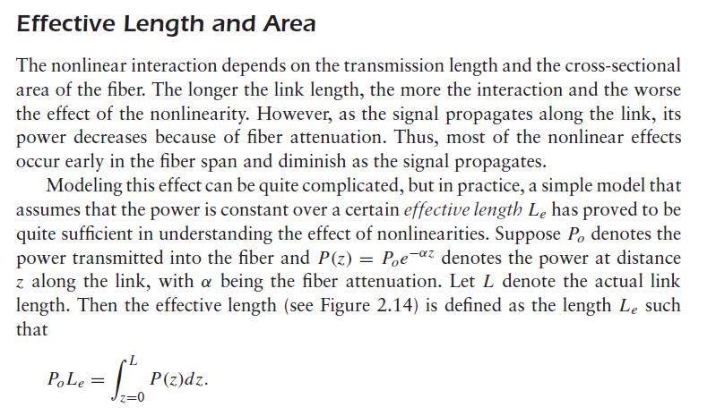
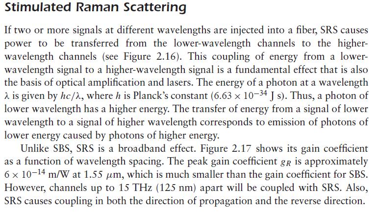
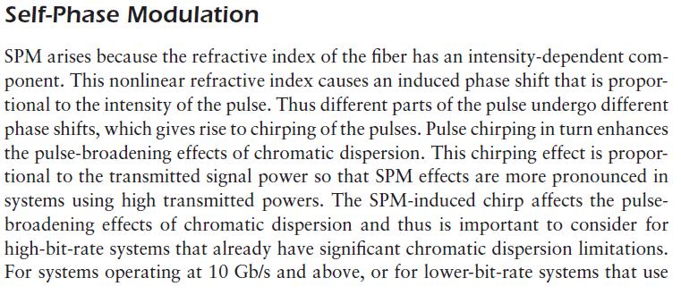
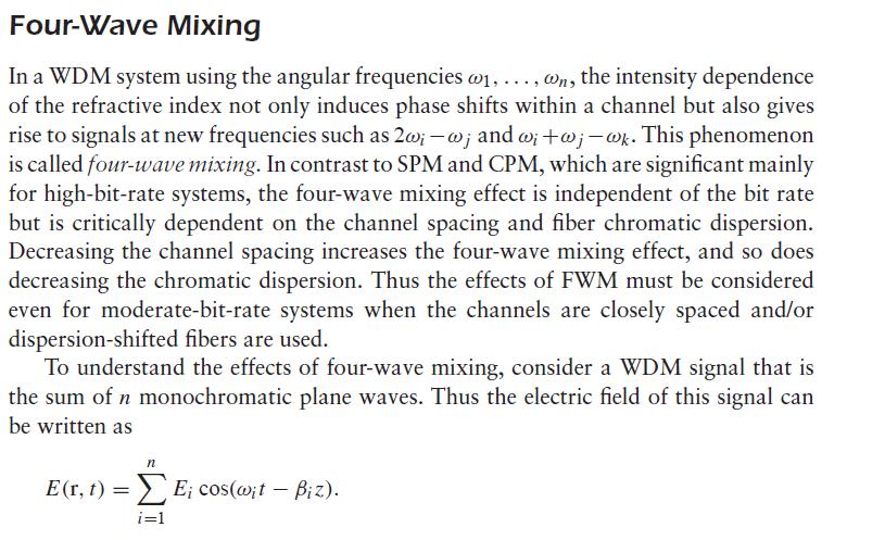
16 6. Explain about the nonlinear effects. [AUC MAY 2013]. There are two categories of nonlinear effects. The first arises due to the interaction of light waves with phonons (molecular vibrations) in the silica medium one of several types of scattering effects, of which we have already met one, namely,rayleigh scattering. The two main effects in this category are stimulated Brillouin scattering (SBS) and stimulated Raman scattering (SRS). The second set of nonlinear effects arises due to the dependence of the refractive index on the intensity of the applied electric field, which in turn is proportional to the square of the field amplitude. The most important nonlinear effects in this category are self-phase modulation (SPM) and four-wave mixing (FWM). In scattering effects, energy gets transferred from one light wave to another wave at a longer wavelength (or lower energy). The lost energy is absorbed by the molecular vibrations, or phonons, in the medium. (The type of phonon involved is different for SBS and SRS.) This second wave is called the Stokes wave. The first wave can be thought of as being a pump wave that causes amplification of the Stokes wave. As the pump propagates in the fiber, it loses power and the Stokes wave gains power. In the case of SBS, the pump wave is the signal wave, and the Stokes wave is the unwanted wave that is generated due to the scattering process. In the case of SRS, the pump wave is a high-power wave, and the Stokes wave is the signal wave that gets amplified at the expense of the pump wave. In general, scattering effects are characterized by a gain coefficient g, measured in meters per watt, and spectral width _f over which the gain is present. The gain coefficient is a measure of the strength of the nonlinear effect. In the case of selfphase modulation, the transmitted pulses undergo chirping. This induced chirp factor becomes significant at high power levels. We have already
17
18
Figure 10.1 Basic structure of SONET
 CHAPTER 10 OPTICAL NETWORKS 10.1 SONET/SDH SONET (Synchronous Optical NETwork) is a standard which was developed in the mid-1980s for fiber optic networks. SONET defines interface standards at the physical
Optical Communications and Networking 朱祖勍. Sept. 25, 2017
 Optical Communications and Networking Sept. 25, 2017 Lecture 4: Signal Propagation in Fiber 1 Nonlinear Effects The assumption of linearity may not always be valid. Nonlinear effects are all related to
Thursday, April 17, 2008, 6:28:40
 Wavelength Division Multiplexing By: Gurudatha Pai K gurudatha@gmail.com Thursday, April 17, 2008, 6:28:40 Overview Introduction Popular Multiplexing Techniques Optical Networking WDM An Analogy of Multiplexing
MODULE IV. End Sem. Exam Marks. Syllabus
 MODULE IV Syllabus Multiplexing- Space Division Multiplexing, Frequency Division Multiplexing, Wave length Division Multiplexing - Time Division multiplexing: Characteristics, Digital Carrier system, SONET/SDH,
OPTICAL NETWORKS. Building Blocks. A. Gençata İTÜ, Dept. Computer Engineering 2005
 OPTICAL NETWORKS Building Blocks A. Gençata İTÜ, Dept. Computer Engineering 2005 Introduction An introduction to WDM devices. optical fiber optical couplers optical receivers optical filters optical amplifiers
WDM. Coarse WDM. Nortel's WDM System
 WDM wavelength-division multiplexing (WDM) is a technology which multiplexes a number of optical carrier signals onto a single optical fiber by using different wavelengths (i.e. colors) of laser light.
Ph.D. Course Spring Wireless Communications. Wirebound Communications
 Ph.D. Course Spring 2005 Danyo Danev associate professor Div. Data Transmission, Dept. Electrical Engineering Linköping University SWEDEN Wireless Communications Radio transmissions Mobile telephony Satellite
Multiplexing. Chapter 8. Frequency Division Multiplexing Diagram. Frequency Division Multiplexing. Multiplexing
 Multiplexing Chapter 8 Multiplexing Frequency Division Multiplexing FDM Useful bandwidth of medium exceeds required bandwidth of channel Each signal is modulated to a different carrier frequency Carrier
Physical Layer. Dr. Sanjay P. Ahuja, Ph.D. Fidelity National Financial Distinguished Professor of CIS. School of Computing, UNF
 Physical Layer Dr. Sanjay P. Ahuja, Ph.D. Fidelity National Financial Distinguished Professor of CIS School of Computing, UNF Multiplexing Transmission channels are expensive. It is often that two communicating
UNIT - 7 WDM CONCEPTS AND COMPONENTS
 UNIT - 7 LECTURE-1 WDM CONCEPTS AND COMPONENTS WDM concepts, overview of WDM operation principles, WDM standards, Mach-Zehender interferometer, multiplexer, Isolators and circulators, direct thin film
Module 19 : WDM Components
 Module 19 : WDM Components Lecture : WDM Components - I Part - I Objectives In this lecture you will learn the following WDM Components Optical Couplers Optical Amplifiers Multiplexers (MUX) Insertion
Module 19 : WDM Components
 Module 19 : WDM Components Lecture : WDM Components - II Objectives In this lecture you will learn the following OADM Optical Circulators Bidirectional OADM using Optical Circulators and FBG Optical Cross
Data and Computer Communications. Tenth Edition by William Stallings
 Data and Computer Communications Tenth Edition by William Stallings Data and Computer Communications, Tenth Edition by William Stallings, (c) Pearson Education - Prentice Hall, 2013 CHAPTER 8 Multiplexing
ITM 1010 Computer and Communication Technologies
 ITM 1010 Computer and Communication Technologies Lecture #14 Part II Introduction to Communication Technologies: Digital Signals: Digital modulation, channel sharing 2003 香港中文大學, 電子工程學系 (Prof. H.K.Tsang)
Introduction to BER testing of WDM systems
 Introduction to BER testing of WDM systems Application note 1299 Wavelength division multiplexing (WDM) is a new and exciting technology for migrating the core optical transmission network to higher bandwidths.
Fiber-Optic Communication Systems
 Fiber-Optic Communication Systems Second Edition GOVIND P. AGRAWAL The Institute of Optics University of Rochester Rochester, NY A WILEY-iNTERSCIENCE PUBLICATION JOHN WILEY & SONS, INC. NEW YORK / CHICHESTER
(Refer Slide Time: 2:23)
") Data Communications Prof. A. Pal Department of Computer Science & Engineering Indian Institute of Technology, Kharagpur Lecture-11B Multiplexing (Contd.) Hello and welcome to today s lecture on multiplexing
Data Communications Prof. A. Pal Department of Computer Science & Engineering Indian Institute of Technology, Kharagpur Lecture-11B Multiplexing (Contd.) Hello and welcome to today s lecture on multiplexing
Optical Transport Tutorial
 Optical Transport Tutorial 4 February 2015 2015 OpticalCloudInfra Proprietary 1 Content Optical Transport Basics Assessment of Optical Communication Quality Bit Error Rate and Q Factor Wavelength Division
Computer Networks
 15-441 Computer Networks Physical Layer Professor Hui Zhang hzhang@cs.cmu.edu 1 Communication & Physical Medium There were communications before computers There were communication networks before computer
Contents for this Presentation. Multi-Service Transport
 Contents for this Presentation SDH/DWDM based Multi-Service Transport Platform by Khurram Shahzad ad Brief Contents Description for this of Presentation the Project Development of a Unified Transport Platform
Optical Communications and Networks - Review and Evolution (OPTI 500) Massoud Karbassian
 Massoud Karbassian") Optical Communications and Networks - Review and Evolution (OPTI 500) Massoud Karbassian m.karbassian@arizona.edu Contents Optical Communications: Review Optical Communications and Photonics Why Photonics?
Optical Communications and Networks - Review and Evolution (OPTI 500) Massoud Karbassian m.karbassian@arizona.edu Contents Optical Communications: Review Optical Communications and Photonics Why Photonics?
21. (i) Briefly explain the evolution of fiber optic system (ii) Compare the configuration of different types of fibers. or 22. (b)(i) Derive modal eq
 Briefly explain the evolution of fiber optic system (ii) Compare the configuration of different types of fibers. or 22. (b)(i) Derive modal eq") Unit-1 Part-A FATIMA MICHAEL COLLEGE OF ENGINEERING & TECHNOLOGY Senkottai Village, Madurai Sivagangai Main Road, Madurai - 625 020. [An ISO 9001:2008 Certified Institution] DEPARTMENT OF ELECTRONICS AND
Unit-1 Part-A FATIMA MICHAEL COLLEGE OF ENGINEERING & TECHNOLOGY Senkottai Village, Madurai Sivagangai Main Road, Madurai - 625 020. [An ISO 9001:2008 Certified Institution] DEPARTMENT OF ELECTRONICS AND
Optical networking. Emilie CAMISARD GIP RENATER Optical technologies engineer Advanced IP Services
 Optical networking Emilie CAMISARD GIP RENATER Optical technologies engineer Advanced IP Services Agenda Optical fibre principle Time Division Multiplexing (TDM) Wavelength Division Multiplexing (WDM)
Multiplexing Module W.tra.2
 Multiplexing Module W.tra.2 Dr.M.Y.Wu@CSE Shanghai Jiaotong University Shanghai, China Dr.W.Shu@ECE University of New Mexico Albuquerque, NM, USA 1 Multiplexing W.tra.2-2 Multiplexing shared medium at
Optical Fiber Enabler of Wireless Devices in the Palms of Your Hands
 Optical Fiber Enabler of Wireless Devices in the Palms of Your Hands A Presentation to EE1001 Class of Electrical Engineering Department at University of Minnesota Duluth By Professor Imran Hayee Smartphone
Wavelength Multiplexing. The Target
 The Target Design a MAN* like fiber network for high data transmission rates. The network is partial below sea level and difficult to install and to maintain. Such a fiber network demands an optimized
Advanced Optical Communications Prof. R. K. Shevgaonkar Department of Electrical Engineering Indian Institute of Technology, Bombay
 Advanced Optical Communications Prof. R. K. Shevgaonkar Department of Electrical Engineering Indian Institute of Technology, Bombay Lecture No. # 27 EDFA In the last lecture, we talked about wavelength
The Physical Layer Outline
 The Physical Layer Outline Theoretical Basis for Data Communications Digital Modulation and Multiplexing Guided Transmission Media (copper and fiber) Public Switched Telephone Network and DSLbased Broadband
EC2402 Optical Fiber Communication and Networks
 EC40 Optical Fiber Communication and Networks UNIT V Optical Networks PREPARED BY G.SUNDAR M.Tech.,MISTE., ASSISTANT PROFESSOR/ECE SEMBODAI RUKMANI VARATHA RAJAN ENGINEERING COLLEGE Network Terminology
CS420/520 Axel Krings Page 1 Sequence 8
 Chapter 8: Multiplexing CS420/520 Axel Krings Page 1 Multiplexing What is multiplexing? Frequency-Division Multiplexing Time-Division Multiplexing (Synchronous) Statistical Time-Division Multiplexing,
Power penalty caused by Stimulated Raman Scattering in WDM Systems
 Paper Power penalty caused by Stimulated Raman Scattering in WDM Systems Sławomir Pietrzyk, Waldemar Szczęsny, and Marian Marciniak Abstract In this paper we present results of an investigation into the
UNIT - 7 WDM CONCEPTS AND COMPONENTS
 UNIT - 7 WDM CONCEPTS AND COMPONENTS WDM concepts, overview of WDM operation principles, WDM standards, Mach-Zehender interferometer, multiplexer, Isolators and circulators, direct thin film filters, active
FIBER OPTICS. Prof. R.K. Shevgaonkar. Department of Electrical Engineering. Indian Institute of Technology, Bombay. Lecture: 37
 FIBER OPTICS Prof. R.K. Shevgaonkar Department of Electrical Engineering Indian Institute of Technology, Bombay Lecture: 37 Introduction to Raman Amplifiers Fiber Optics, Prof. R.K. Shevgaonkar, Dept.
Dr. Monir Hossen ECE, KUET
 Dr. Monir Hossen ECE, KUET 1 Outlines of the Class Principles of WDM DWDM, CWDM, Bidirectional WDM Components of WDM AWG, filter Problems with WDM Four-wave mixing Stimulated Brillouin scattering WDM Network
Practical Aspects of Raman Amplifier
 Practical Aspects of Raman Amplifier Contents Introduction Background Information Common Types of Raman Amplifiers Principle Theory of Raman Gain Noise Sources Related Information Introduction This document
CHAPTER 5 SPECTRAL EFFICIENCY IN DWDM
 61 CHAPTER 5 SPECTRAL EFFICIENCY IN DWDM 5.1 SPECTRAL EFFICIENCY IN DWDM Due to the ever-expanding Internet data traffic, telecommunication networks are witnessing a demand for high-speed data transfer.
Data and Computer Communications. Tenth Edition by William Stallings
 Data and Computer Communications Tenth Edition by William Stallings Data and Computer Communications, Tenth Edition by William Stallings, (c) Pearson Education, 2013 CHAPTER 8 Multiplexing It was impossible
Chapter 8. Wavelength-Division Multiplexing (WDM) Part II: Amplifiers
 Part II: Amplifiers") Chapter 8 Wavelength-Division Multiplexing (WDM) Part II: Amplifiers Introduction Traditionally, when setting up an optical link, one formulates a power budget and adds repeaters when the path loss exceeds
Chapter 8 Wavelength-Division Multiplexing (WDM) Part II: Amplifiers Introduction Traditionally, when setting up an optical link, one formulates a power budget and adds repeaters when the path loss exceeds
FIBER OPTICS. Prof. R.K. Shevgaonkar. Department of Electrical Engineering. Indian Institute of Technology, Bombay. Lecture: 26
 FIBER OPTICS Prof. R.K. Shevgaonkar Department of Electrical Engineering Indian Institute of Technology, Bombay Lecture: 26 Wavelength Division Multiplexed (WDM) Systems Fiber Optics, Prof. R.K. Shevgaonkar,
S Optical Networks Course Lecture 4: Transmission System Engineering
 S-72.3340 Optical Networks Course Lecture 4: Transmission System Engineering Edward Mutafungwa Communications Laboratory, Helsinki University of Technology, P. O. Box 2300, FIN-02015 TKK, Finland Tel:
Optical Communications and Networks - Review and Evolution (OPTI 500) Massoud Karbassian
 Massoud Karbassian") Optical Communications and Networks - Review and Evolution (OPTI 500) Massoud Karbassian m.karbassian@arizona.edu Contents Optical Communications: Review Optical Communications and Photonics Why Photonics?
Optical Communications and Networks - Review and Evolution (OPTI 500) Massoud Karbassian m.karbassian@arizona.edu Contents Optical Communications: Review Optical Communications and Photonics Why Photonics?
TELECOMMUNICATION SYSTEMS
 TELECOMMUNICATION SYSTEMS By Syed Bakhtawar Shah Abid Lecturer in Computer Science 1 MULTIPLEXING An efficient system maximizes the utilization of all resources. Bandwidth is one of the most precious resources
Chapter 12: Optical Amplifiers: Erbium Doped Fiber Amplifiers (EDFAs)
") Chapter 12: Optical Amplifiers: Erbium Doped Fiber Amplifiers (EDFAs) Prof. Dr. Yaocheng SHI ( 时尧成 ) yaocheng@zju.edu.cn http://mypage.zju.edu.cn/yaocheng 1 Traditional Optical Communication System Loss
Chapter 12: Optical Amplifiers: Erbium Doped Fiber Amplifiers (EDFAs) Prof. Dr. Yaocheng SHI ( 时尧成 ) yaocheng@zju.edu.cn http://mypage.zju.edu.cn/yaocheng 1 Traditional Optical Communication System Loss
CHAPTER ONE INTRODUCTION
 CHAPTER ONE INTRODUCTION 1.1 Background A communication system transmits information from one place to another, whether separated by a few kilometers or by transoceanic distances. Information is often
EEE 309 Communication Theory
 EEE 309 Communication Theory Semester: January 2016 Dr. Md. Farhad Hossain Associate Professor Department of EEE, BUET Email: mfarhadhossain@eee.buet.ac.bd Office: ECE 331, ECE Building Part 08 Multiplexing
Computer Networks: Multiplexing
 Computer Networks: Multiplexing EE1001 Prof. Taek M. Kwon Department of Electrical Engineering, UMD Outline EE 4321 Multiplexing EE 4321: Computer Networks EE Technical Elective Course, 3 credits Network
UNIVERSITY OF TORONTO FACULTY OF APPLIED SCIENCE AND ENGINEERING. FINAL EXAMINATION, April 2017 DURATION: 2.5 hours
 UNIVERSITY OF TORONTO FACULTY OF APPLIED SCIENCE AND ENGINEERING ECE4691-111 S - FINAL EXAMINATION, April 2017 DURATION: 2.5 hours Optical Communication and Networks Calculator Type: 2 Exam Type: X Examiner:
S.D.M COLLEGE OF ENGINEERING AND TECHNOLOGY
 VISHVESHWARAIAH TECHNOLOGICAL UNIVERSITY S.D.M COLLEGE OF ENGINEERING AND TECHNOLOGY A seminar report on Orthogonal Frequency Division Multiplexing (OFDM) Submitted by Sandeep Katakol 2SD06CS085 8th semester
ET4254 Communications and Networking 1
 Topic 5 Look at multiplexing multiple channels on a single link FDM TDM Statistical TDM ASDL and xdsl 1 Multiplexing multiple links on 1 physical line common on long-haul, high capacity, links have FDM,
DWDM Theory. ZTE Corporation Transmission Course Team. ZTE University
 DWDM Theory ZTE Corporation Transmission Course Team DWDM Overview Multiplexing Technology WDM TDM SDM What is DWDM? Gas Station High Way Prowl Car Definition l 1 l 2 l N l 1 l 2 l 1 l 2 l N OA l N OMU
Module 3: Physical Layer
 Module 3: Physical Layer Dr. Associate Professor of Computer Science Jackson State University Jackson, MS 39217 Phone: 601-979-3661 E-mail: natarajan.meghanathan@jsums.edu 1 Topics 3.1 Signal Levels: Baud
Datenkommunikation SS L03 - TDM Techniques. Time Division Multiplexing (synchronous, statistical) Digital Voice Transmission, PDH, SDH
 Digital Voice Transmission, PDH, SDH") TM Techniques Time ivision Multiplexing (synchronous, statistical) igital Voice Transmission, PH, SH Agenda Introduction Synchronous (eterministic) TM Asynchronous (Statistical) TM igital Voice Transmission
TM Techniques Time ivision Multiplexing (synchronous, statistical) igital Voice Transmission, PH, SH Agenda Introduction Synchronous (eterministic) TM Asynchronous (Statistical) TM igital Voice Transmission
SYLLABUS Optical Fiber Communication
 SYLLABUS Optical Fiber Communication Subject Code : IA Marks : 25 No. of Lecture Hrs/Week : 04 Exam Hours : 03 Total no. of Lecture Hrs. : 52 Exam Marks : 100 UNIT - 1 PART - A OVERVIEW OF OPTICAL FIBER
Reti di Telecomunicazione. Channels and Multiplexing
 Reti di Telecomunicazione Channels and Multiplexing Point-to-point Channels They are permanent connections between a sender and a receiver The receiver can be designed and optimized based on the (only)
Simulation of Optical CDMA using OOC Code
 International Journal of Scientific and Research Publications, Volume 2, Issue 5, May 22 ISSN 225-353 Simulation of Optical CDMA using OOC Code Mrs. Anita Borude, Prof. Shobha Krishnan Department of Electronics
Pass Cisco Exam
 Pass Cisco 642-321 Exam Number: 642-321 Passing Score: 800 Time Limit: 120 min File Version: 38.8 http://www.gratisexam.com/ Pass Cisco 642-321 Exam Exam Name : Cisco Optical SDH Exam (SDH) Braindumps
Bandwidth utilization is the wise use of available bandwidth to achieve specific goals.
 Note Bandwidth Utilization: Multiplexing and Spreading Bandwidth utilization is the wise use of available bandwidth to achieve specific goals. Efficiency can be achieved by multiplexing; i.e., sharing
Analyzing the Non-Linear Effects in DWDM Optical Network Using MDRZ Modulation Format
 Analyzing the Non-Linear Effects in DWDM Optical Network Using MDRZ Modulation Format Ami R. Lavingia Electronics & Communication Dept. SAL Institute of Technology & Engineering Research Gujarat Technological
International Journal of Engineering Research & Technology (IJERT) ISSN: Vol. 2 Issue 9, September
 ISSN: Vol. 2 Issue 9, September") Performance Enhancement of WDM-ROF Networks With SOA-MZI Shalu (M.Tech), Baljeet Kaur (Assistant Professor) Department of Electronics and Communication Guru Nanak Dev Engineering College, Ludhiana Abstract
Performance Enhancement of WDM-ROF Networks With SOA-MZI Shalu (M.Tech), Baljeet Kaur (Assistant Professor) Department of Electronics and Communication Guru Nanak Dev Engineering College, Ludhiana Abstract
Dr. Rüdiger Paschotta RP Photonics Consulting GmbH. Competence Area: Fiber Devices
 Dr. Rüdiger Paschotta RP Photonics Consulting GmbH Competence Area: Fiber Devices Topics in this Area Fiber lasers, including exotic types Fiber amplifiers, including telecom-type devices and high power
A review on optical time division multiplexing (OTDM)
") International Journal of Academic Research and Development ISSN: 2455-4197 Impact Factor: RJIF 5.22 www.academicsjournal.com Volume 3; Issue 1; January 2018; Page No. 520-524 A review on optical time division
International Journal of Academic Research and Development ISSN: 2455-4197 Impact Factor: RJIF 5.22 www.academicsjournal.com Volume 3; Issue 1; January 2018; Page No. 520-524 A review on optical time division
Optical DWDM Networks
 Optical DWDM Networks ain The Oh Columbus, OH 43210 Jain@CIS.Ohio-State.Edu These slides are available at http://www.cis.ohio-state.edu/~jain/cis788-99/ 1 Overview Sparse and Dense WDM Recent WDM Records
Optical Transport Technologies and Trends
 Optical Transport Technologies and Trends A Network Planning Perspective Sept 1, 2014 Dion Leung, Director of Solutions and Sales Engineering dleung@btisystem.com About BTI Customers 380+ worldwide in
Technical Aspects of LTE Part I: OFDM
 Technical Aspects of LTE Part I: OFDM By Mohammad Movahhedian, Ph.D., MIET, MIEEE m.movahhedian@mci.ir ITU regional workshop on Long-Term Evolution 9-11 Dec. 2013 Outline Motivation for LTE LTE Network
Dynamic gain-tilt compensation using electronic variable optical attenuators and a thin film filter spectral tilt monitor
 Dynamic gain-tilt compensation using electronic variable optical attenuators and a thin film filter spectral tilt monitor P. S. Chan, C. Y. Chow, and H. K. Tsang Department of Electronic Engineering, The
SOME PHYSICAL LAYER ISSUES. Lecture Notes 2A
 SOME PHYSICAL LAYER ISSUES Lecture Notes 2A Delays in networks Propagation time or propagation delay, t prop Time required for a signal or waveform to propagate (or move) from one point to another point.
Optical Fibers p. 1 Basic Concepts p. 1 Step-Index Fibers p. 2 Graded-Index Fibers p. 4 Design and Fabrication p. 6 Silica Fibers p.
 Preface p. xiii Optical Fibers p. 1 Basic Concepts p. 1 Step-Index Fibers p. 2 Graded-Index Fibers p. 4 Design and Fabrication p. 6 Silica Fibers p. 6 Plastic Optical Fibers p. 9 Microstructure Optical
Bandwidth Utilization:
 CHAPTER 6 Bandwidth Utilization: In real life, we have links with limited bandwidths. The wise use of these bandwidths has been, and will be, one of the main challenges of electronic communications. However,
Advanced Fibre Testing: Paving the Way for High-Speed Networks. Trevor Nord Application Specialist JDSU (UK) Ltd
 Ltd") Advanced Fibre Testing: Paving the Way for High-Speed Networks Trevor Nord Application Specialist JDSU (UK) Ltd Fibre Review Singlemode Optical Fibre Elements of Loss Fibre Attenuation - Caused by scattering
Advanced Fibre Testing: Paving the Way for High-Speed Networks Trevor Nord Application Specialist JDSU (UK) Ltd Fibre Review Singlemode Optical Fibre Elements of Loss Fibre Attenuation - Caused by scattering
SCTE. San Diego Chapter March 19, 2014
 SCTE San Diego Chapter March 19, 2014 RFOG WHAT IS RFOG? WHY AND WHERE IS THIS TECHNOLOGY A CONSIDERATION? RFoG could be considered the deepest fiber version of HFC RFoG pushes fiber to the side of the
MAHALAKSHMI ENGINEERING COLLEGE TIRUCHIRAPALLI
 MAHALAKSHMI ENGINEERING COLLEGE TIRUCHIRAPALLI - 621213 DEPARTMENT : ECE SUBJECT NAME : OPTICAL COMMUNICATION & NETWORKS SUBJECT CODE : EC 2402 UNIT II: TRANSMISSION CHARACTERISTICS OF OPTICAL FIBERS PART
International Journal of Advanced Research in Computer Science and Software Engineering
 ISSN: 2277 128X International Journal of Advanced Research in Computer Science and Software Engineering Research Paper Available online at: Performance Analysis of WDM/SCM System Using EDFA Mukesh Kumar
! Couplers. ! Isolators/Circulators. ! Multiplexers/Filters. ! Optical Amplifiers. ! Transmitters (lasers,leds) ! Detectors (receivers) !
 ! Detectors (receivers) !") Components of Optical Networks Based on: Rajiv Ramaswami, Kumar N. Sivarajan, Optical Networks A Practical Perspective 2 nd Edition, 2001 October, Morgan Kaufman Publishers Optical Components! Couplers!
Components of Optical Networks Based on: Rajiv Ramaswami, Kumar N. Sivarajan, Optical Networks A Practical Perspective 2 nd Edition, 2001 October, Morgan Kaufman Publishers Optical Components! Couplers!
Elements of Optical Networking
 Bruckner Elements of Optical Networking Basics and practice of optical data communication With 217 Figures, 13 Tables and 93 Exercises Translated by Patricia Joliet VIEWEG+ TEUBNER VII Content Preface
The problem of upstream traffic synchronization in Passive Optical Networks
 The problem of upstream traffic synchronization in Passive Optical Networks Glen Kramer Department of Computer Science University of California Davis, CA 95616 kramer@cs.ucdavis.edu Abstaract. Recently
Types of losses in optical fiber cable are: Due to attenuation, the power of light wave decreases exponentially with distance.
 UNIT-II TRANSMISSION CHARACTERISTICS OF OPTICAL FIBERS SIGNAL ATTENUATION: Signal attenuation in an optical fiber is defined as the decrease in light power during light propagation along an optical fiber.
Exam : : Cisco Optical SONET Exam. Title. Ver :
 Exam : 642-311 Title : Cisco Optical SONET Exam Ver : 10.05.07 QUESTION 1: The exhibit shows a 15454/15216 DWDM system and alarm indications. What are two possible sources of trouble shown in the system?
William Stallings Data and Computer Communications. Chapter 8 Multiplexing. Multiplexing
 William Stallings Data and Computer Communications Chapter 8 Multiplexing Multiplexing 1 Frequency Division Multiplexing FDM Useful bandwidth of medium exceeds required bandwidth of channel Each signal
Lecture 5 Transmission
 Lecture 5 Transmission David Andersen Department of Computer Science Carnegie Mellon University 15-441 Networking, Spring 2005 http://www.cs.cmu.edu/~srini/15-441/s05 1 Physical and Datalink Layers: 3
Multiplexing Concepts and Introduction to BISDN. Professor Richard Harris
 Multiplexing Concepts and Introduction to BISDN Professor Richard Harris Objectives Define what is meant by multiplexing and demultiplexing Identify the main types of multiplexing Space Division Time Division
Contents. Telecom Systems Chae Y. Lee. FDM Bell Systems s FDM Synchronous TDM T1, T3 Statistical TDM Multiple Access: FDMA, TDMA, CDMA
 Multiplexing Contents FDM Bell Systems s FDM Synchronous TDM T1, T3 Statistical TDM Multiple Access: FDMA, TDMA, CDMA 2 Multiplexing/Demultiplexing Multiplexing is the process of combining two or more
<#)*,$+0"$#)* ?">& B"$"')*+0"$#)* ?">&? F. S. Blair March 24, Analog and Digital Signals
*,$+0$#)* ?>& B$')*+0$#)* ?>&? F. S. Blair March 24, Analog and Digital Signals") S. Blair March 24, 2008 8 1.5. Analog and Digital Signals
S. Blair March 24, 2008 8 1.5. Analog and Digital Signals
WDM Concept and Components. EE 8114 Course Notes
 WDM Concept and Components EE 8114 Course Notes Part 1: WDM Concept Evolution of the Technology Why WDM? Capacity upgrade of existing fiber networks (without adding fibers) Transparency:Each optical channel
Chapter 6 Bandwidth Utilization: Multiplexing and Spreading 6.1
 Chapter 6 Bandwidth Utilization: Multiplexing and Spreading 6.1 Copyright The McGraw-Hill Companies, Inc. Permission required for reproduction or display. 3-6 PERFORMANCE One important issue in networking
INTRODUCTION TO COMMUNICATION SYSTEMS AND TRANSMISSION MEDIA
 COMM.ENG INTRODUCTION TO COMMUNICATION SYSTEMS AND TRANSMISSION MEDIA 9/9/2017 LECTURES 1 Objectives To give a background on Communication system components and channels (media) A distinction between analogue
Optical Fiber Communications p. 1 Introduction p. 1 History of Optical Fibers p. 1 Optical Fibers Versus Metallic Cable Facilities p.
 Optical Fiber Communications p. 1 Introduction p. 1 History of Optical Fibers p. 1 Optical Fibers Versus Metallic Cable Facilities p. 2 Advantages of Optical Fiber Systems p. 3 Disadvantages of Optical
Lecture 2. Introduction to Optical. Ivan Avrutsky, ECE 5870 Optical Communication Networks, Lecture 2. Slide 1
 Lecture 2 Introduction to Optical Networks Ivan Avrutsky, ECE 5870 Optical Communication Networks, Lecture 2 Slide 1 Optical Communication Networks 1. Why optical? 2. How does it work? 3. How to design
ANALYSIS OF DISPERSION COMPENSATION IN A SINGLE MODE OPTICAL FIBER COMMUNICATION SYSTEM
 ANAYSIS OF DISPERSION COMPENSATION IN A SINGE MODE OPTICA FIBER COMMUNICATION SYSTEM Sani Abdullahi Mohammed 1, Engr. Yahya Adamu and Engr. Matthew Kwatri uka 3 1,,3 Department of Electrical and Electronics
Chirped Bragg Grating Dispersion Compensation in Dense Wavelength Division Multiplexing Optical Long-Haul Networks
 363 Chirped Bragg Grating Dispersion Compensation in Dense Wavelength Division Multiplexing Optical Long-Haul Networks CHAOUI Fahd 3, HAJAJI Anas 1, AGHZOUT Otman 2,4, CHAKKOUR Mounia 3, EL YAKHLOUFI Mounir
Impact of Fiber Non-Linearities in Performance of Optical Communication
 Impact of Fiber Non-Linearities in Performance of Optical Communication Narender Kumar Sihval 1, Vivek Kumar Malik 2 M. Tech Students in ECE Department, DCRUST-Murthal, Sonipat, India Abstract: Non-linearity
Optical Networks and Transceivers. OPTI 500A, Lecture 2, Fall 2012
 Optical Networks and Transceivers OPTI 500A, Lecture 2, Fall 2012 1 The Simplest Network Topology Network Node Network Node Transmission Link 2 Bus Topology Very easy to add a device to the bus Common
Agilent 83430A Lightwave Digital Source Product Overview
 Agilent Lightwave Digital Source Product Overview SDH/SONET Compliant DFB laser source for digital, WDM, and analog test up to 2.5 Gb/s 52 Mb/s STM-0/OC-1 155 Mb/s STM-1/OC-3 622 Mb/s STM-4/OC-12 2488
LW Technology. Passive Components. LW Technology (Passive Components).PPT - 1 Copyright 1999, Agilent Technologies
.PPT - 1 Copyright 1999, Agilent Technologies") LW Technology Passive Components LW Technology (Passive Components).PPT - 1 Patchcords Jumper cables to connect devices and instruments Adapter cables to connect interfaces using different connector styles
LW Technology Passive Components LW Technology (Passive Components).PPT - 1 Patchcords Jumper cables to connect devices and instruments Adapter cables to connect interfaces using different connector styles
About the Tutorial. Audience. Prerequisites. Disclaimer & Copyright
 About the Tutorial Next Generation Networks (NGN) is a part of present-day telecommunication system, which is equipped with capabilities to transport all sorts of media, such as voice, video, streaming
Data Communications and Networks
 Data Communications and Networks Engr. Abdul Rahman Mahmood MS, MCP, QMR(ISO9001:2000) Usman Institute of Technology University Road, Karachi armahmood786@yahoo.com alphasecure@gmail.com alphapeeler.sf.net/pubkeys/pkey.htm
ECEN689: Special Topics in Optical Interconnects Circuits and Systems Spring 2016
 ECEN689: Special Topics in Optical Interconnects Circuits and Systems Spring 016 Lecture 7: Transmitter Analysis Sam Palermo Analog & Mixed-Signal Center Texas A&M University Optical Modulation Techniques
SC - Single carrier systems One carrier carries data stream
 Digital modulation SC - Single carrier systems One carrier carries data stream MC - Multi-carrier systems Many carriers are used for data transmission. Data stream is divided into sub-streams and each
EE 304 TELECOMMUNICATIONs ESSENTIALS HOMEWORK QUESTIONS AND ANSWERS
 Homework Question 1 EE 304 TELECOMMUNICATIONs ESSENTIALS HOMEWORK QUESTIONS AND ANSWERS Allocated channel bandwidth for commercial TV is 6 MHz. a. Find the maximum number of analog voice channels that
INTRODUCTION. LPL App Note RF IN G 1 F 1. Laser Diode OPTICAL OUT. P out. Link Length. P in OPTICAL IN. Photodiode G 2 F 2 RF OUT
 INTRODUCTION RF IN Today s system designer may be faced with several technology choices for communications links for satellite microwave remoting, cellular/broadband services, or distribution of microwave
PH-7. Understanding of FWM Behavior in 2-D Time-Spreading Wavelength- Hopping OCDMA Systems. Abstract. Taher M. Bazan Egyptian Armed Forces
 PH-7 Understanding of FWM Behavior in 2-D Time-Spreading Wavelength- Hopping OCDMA Systems Taher M. Bazan Egyptian Armed Forces Abstract The behavior of four-wave mixing (FWM) in 2-D time-spreading wavelength-hopping