Talk Back Intercom System
|
|
|
- Blaze Lawrence Gilbert
- 5 years ago
- Views:
Transcription


1 Talk Back Intercom System Model TBA P Rev. D /24/ :32 AM Ph: \ info@guardiantelecom.com \
2 Contents 1. Purpose Scope Identification of equipment TBA Model Numbering TBA Front Panel TBA Rear Panel TBA Enclosure Inside System Overview Central Station Monitored Station Stations #1, #2 and # PTT Actions Alert or Go-Ahead Tone Applications on Drilling Rigs Applications on Shipboard Application Restrictions Installation Instructions TBA Enclosure AC Supply VAC operation DC Supply Options Push to Talk Switches Microphone Speaker TBA Configurations except for TBA TBA-33 Configuration Installation Adjustments Initial Settings Powering ON the TBA Monitored Station Microphone Volume Adjustment Central Station Microphone Volume Adjustment Ringer Volume Adjustment Central Station Speaker Volume Station #1 Speaker Volume Station #2 Speaker Volume Station #3 Speaker Volume Optional Hum Cancellation Optional ringing from PTTs Replace the TBA enclosure top panel Locations of adjustments for the TBA Audio transformer tap adjustments Product Specifications...22 Page 2
3 12. Replacement Parts Warranty Disclaimer Warning Service Telephone Number Feedback Guardian Product Return...25 Figures Figure 1 - Table of...4 Figure 2 TBA-41 Front Panel...5 Figure 3 TBA-41 Rear Panel...5 Figure 4 - TBA Enclosure Inside Front...6 Figure 5 - TBA Enclosure Inside Rear...6 Figure 6 - TBA External Audio Connections...11 Figure 7 - TBA Internal Audio Connections...12 Figure 8 - TBA-33 Internal Audio Connections to Figure 9 - TBA-33 Internal Transformer Wiring Pre Figure 10 - TBA-33 Internal Audio Connections Starting Figure 11 - TBA-33 Internal Transformer Connections...16 Figure 12 - Station Connector Wiring...17 Figure 13 - Central Station Microphone Wiring...17 Figure 14 - Central Station Speaker Wiring...18 Figure 15 - Adjustment Locations...21 Package Contents (1) TBA Talk Back Amplifier (1) Loudspeaker Additional Loudspeakers (optional up to four) (1) Optional Central Station Microphone (except for model TBA-22) (1) Manual Acronyms: TBA Talk Back Amplifier PWB Printed Wiring Board PWBA Printed Wiring Board Assembly AC Alternating Current DC Direct Current KHz Thousand Hertz Hz Cycles per second Page 3
4 1. Purpose This document is provided to assist in the electrical installation and operation of a Talk Back Amplifier (TBA) as produced by Guardian Telecom Inc. 2. Scope The installation information will consist of connections to the TBA unit in the enclosure. The connections to external speakers and microphones are covered in their respective manuals. The operation information will consist of adjustment of potentiometers and power supply requirements for the TBA unit. Some information for the speaker and microphone sensitivity that relates to the TBA operation will be given to assist in the selection and installation of TBA peripherals. 3. Identification of equipment There are several models of Guardian Talk Back Amplifiers (TBA). The Printed Wiring Board Assembly (PWBA) in the TBA will support up to five speaker outputs; therefore the listing of equipment goes from five speaker outputs to two speaker outputs TBA Model Numbering The table below uses CEN for Central Station, MON for Monitored Station and #1 to #3 for Stations #1 to #3. The X in a square indicates that the speaker amplifier is populated on the PWBA. The L indicates low impedance and the H indicates high impedance. Figure 1 - Table of Note: The Central Station input for the microphone on TBA-33 is modified to have an impedance of near 1K Ohm when the PTT is not pressed. See the section titled Microphone for further information. Page 4


5 3.2. TBA Front Panel The TBA Front Panel of the enclosure has from two to five volume controls and a power indicator. The power indicator shows the presence of AC power, and is a green illumination if AC is present. The volume controls are labeled for the Station being controlled. Clockwise rotation gives more volume, the volume controls have numbers from1 to 10 to assist in setting repeatability. Figure 2 TBA-41 Front Panel 3.3. TBA Rear Panel The TBA Rear Panel of the enclosure has from two to five cable entries, an AC power connector, an AC fuse and a Power ON/OFF switch. The AC power connector is a standard connector for AC supplies. The AC fuse is a 1 amp slow blow 250 volt fuse of 1.25 long and 0.25 diameter. Buss fuse type MDL 1A is supplied with the TBA. The POWER ON/OFF switch is a rocker switch; pushing the switch upwards turns on the TBA. Figure 3 TBA-41 Rear Panel Page 5


6 3.4. TBA Enclosure Inside The photos below show the TBA-50 with the top cover removed. Figure 4 - TBA Enclosure Inside Front Figure 5 - TBA Enclosure Inside Rear Page 6
7 4. System Overview The Talk Back Amplifier (TBA) is so named because of the ability for the user to talk back to the speakers instead of using a separate microphone to talk back. The model TBA is an intercom system designed for use in situations where frequent communications between two or more stations are required. The TBA system utilizes speakers in two modes: as a speaker output to broadcast audio messages from other stations as an audio microphone to pick up audio messages Central Station The Central Station speaker normally outputs audio coming from the Monitored Station. The audio from the Monitored Station or Stations #1, #2 or #3 with their PTT depressed, will be output on the Central Station speaker. To output audio the Central Station user presses the Press to Talk (PTT) switch. The Central Station PTT switch is normally mounted on the microphone housing, but it may be a foot switch. The Central station is different from the other stations in that it has a separate microphone input as well as a speaker output. The Central Station speaker also has a low level sidetone audio from the speaker to allow the user to hear that the Central Station audio output is working. The Central Station console consists of a (goose neck) dynamic microphone and a hand switch or pedal switch for PTT. The Central Station has the highest priority in using PTT. When the Central Station PTT switch is engaged (depressed) the TBA puts a low level audio onto the Central Station speaker. This low level is to prevent acoustical feedback. The other speakers in the system are set to the speaker mode and output audio coming from the Central Station Monitored Station The Monitored Station is different from the other stations in that it will continuously send the audio heard at its speaker to the other stations when no Press to Talk (PTT) switch in the TBA is depressed. The Central Station and up to three stations normally output audio coming from the Monitored Station to their speakers. The PTT switch on the Monitored Station is used only as a Ringing or Alert Tone activation. Pressing the Monitored Station PTT will stop the audio output from the Monitored Station and put a Ringing tone onto the Central Station, Monitored Station and the other stations speakers. The Monitored Station speaker will output the audio coming from another station if the other station presses a PTT switch. When the Monitored Station speaker is outputting audio it does not send audio to the other stations. The Monitored Station speaker will change from a microphone input into a speaker output when the Central Station or another station has the PTT switch pressed Stations #1, #2 and #3 The Stations #1, #2 and #3 have a speaker and a PTT switch. The audio from the Monitored Station or any other station with a PTT depressed will be output on that station s speaker. When the station s PTT switch is depressed the station will output audio to the other stations. When the speaker is outputting audio it does not receive audio from the other stations. Page 7
8 4.4. PTT Actions The Central Station Push to Talk (PTT) switch has the highest priority in using PTT. When the PTT is pressed on the Monitored or Stations #1, #2 or #3 the stations are a first-come first-served basis for PTT. When the PTT switch on the Monitored Station is pressed the other speakers on the system will output a ringing tone for as long as the PTT is pressed. When the PTT switch on the Central Station, Stations #1, #2 or #3 is pressed the system will use the speaker on that station to generate audio for the other station speakers Alert or Go-Ahead Tone The Talk Back Amplifier (TBA) has a tone generator that sounds similar to a telephone ringing. This dual tone ( Ringing ) is generated for two purposes: Alert Go-Ahead The Alert Tone or Ringing is caused by the Monitored Station pushing the Push to Talk (PTT) switch. The Go-Ahead short Ringing is a 0.1 second long sound burst that indicates to the users that a PTT switch has just been released on the Central Station or Station #1, #2 or #3. This Go-Ahead indicates that the other station has ceased pressing the PTT switch and that normal operation can be resumed. When this post announcement short Ringing tone is heard it confirms to the listener that the system is in the receive mode. Jumper JP1 on the Printed Circuit Board Assembly (PCBA) is a switch to allow the injection of the post PTT Go-Ahead or short Ringing tone. Moving JP1 to the bottom set of terminals will disable the Go-Ahead or short Ringing tone Applications on Drilling Rigs In drilling rig applications the TBA normally consists of: Central Station at the doghouse with a speaker and microphone Monitored Station at the monkey board Station #1, #2 and #3 as needed. The monkey board or racking board for the derrick man is up on the drilling rig tower, and the derrick man s instructions to the dog house (driller s communication shack) should be continuously monitored Applications on Shipboard Audio monitoring of the wheelhouse or control station can be used to inform the engine room and other stations of the actions needed to be performed. In this way commands for ship operation can be communicated without delay by the ship operator simply speaking. The telephone intercom on board the ship is connected to a special impedance of the Central Station made for the 600 Ohm telephone system. A PTT from the telephone line is used to activate the output to the talk back speakers both FORE and AFT. After the PTT the FORE and AFT can reply back to the telephone system by talking to the speakers. The period for the FORE and AFT stations to talk back after a PTT is received from the telephone interface is selected by a jumper on Monitored Station PTT for 1 minute, or a jumper on Station #1 PTT for 10 minutes. 5. Application Restrictions The Talk Back Amplifier (TBA) enclosure is not approved for use in hazardous areas. The Central Station console microphone (as supplied) is not approved for use in hazardous areas. A microphone may be used in hazardous areas if it is connected through an approved intrinsically safe barrier. Page 8
9 The Push to Talk (PTT) switches may be of a suitable rating for use in hazardous areas, or connected through an approved intrinsically safe barrier. Any application of equipment into a hazardous area must be approved by the appropriate authority. The speakers used may be of a suitable rating for use in hazardous areas. The speakers used with the system may or may not be approved, check the labels on the speakers for ratings. Follow all local codes and requirements when installing the TBA Intercom System. The TBA does not have a weatherproof or drip-proof rating, and is not protected for prolonged exposure to high humidity and salt fog. 6. Installation Instructions The Talk Back Amplifier (TBA) is an audio amplifier that has been designed to operate in a commercial setting. In order to obtain the best results, use shielded cable and follow the instructions below TBA Enclosure The TBA enclosure houses the Printed Wiring Board Assembly (PWBA) within a steel enclosure that has a removable top cover. A wiring diagram is on the inside of the cover. The enclosure may be placed on a flat surface, mounted in an equipment rack or otherwise securely mounted. The TBA enclosure can dissipate up to 110 watts with all of the speaker amplifiers outputting maximum energy. There must be adequate heat conduction so that the enclosure does not exceed 20 deg above ambient with 110 watts dissipation. An air flow caused by convection with a 1 inch gap to surrounding side walls is normally adequate. If in doubt, test the temperature rise using a heater of 100 watts in the case and measure the resultant temperature after 1 hour. The TBA enclosure top panel may be removed by unfastening the six screws. Once the top panel has been removed, access to 120 volts AC is provided; therefore the service personnel should be qualified to work with electrical equipment. The TBA amplifier enclosure is painted and uses stainless steel hardware internally. The components within the enclosure are not waterproof or corrosion resistant so the enclosure should not be used in a corrosive or contaminated environment AC Supply The Talk Back Amplifier uses 120 VAC at 60 Hz with a maximum of 1 amp continuous current for energy supply. Note that the inrush current may be up to 10 amps for a fraction of a second. There is an inrush surge reduction circuit that reduces the capacitive charging surge on power-on. This circuit can be evaluated for inrush surge reduction if there is a problem with the external 120 volt power current surge capability VAC operation A 230 VAC to 24 VAC transformer can be special ordered for the TBA. The input voltage labeling and serial number label must be changed or marked to indicate this change. The front panel Power ON indicator must also be changed for 230 VAC operation DC Supply Options The use of a separate DC supply for 27 to 35 volts (0.5 amps maximum) is possible to replace the internal supply of the TBA logic and preamplifier sections for supply to J22 pins 1 and 3. The negative ground connection is available at J22 pin 3 and positive is attached to J22 pin 1. The use of a separate 30 to 70 volt supply (10 amps maximum) can be applied separately for the audio power amplifiers if the jumper on J22 pin 1 to 2 is removed. The negative ground connection is available at J22 pin 3. If this option is used, the internal transformer for 8 to 325 Ohms is to be removed and the amplifier will drive the 70 volt line directly. Note that the DC supply generated within the TBA is floating with respect to the chassis ground. Verify that the negative at J22 pin 3 (PWBA ground) has a low voltage and low audio frequency noise with respect to chassis ground if there is noise present on the Talk Back Amplifier system. Page 9
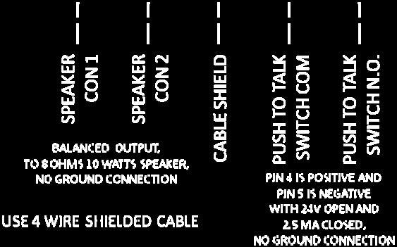
10 6.3. Push to Talk Switches The Talk Back Amplifier has a 24 volt resistive connection to Push to Talk (PTT) switches. The use of gold or silver plated switch contacts within an environmentally sealed housing is recommended for long term reliability. The switches will conduct about 0.5 milliamp when pressed, and have 24 volts across the terminals when not pressed. Each of these connections should be evaluated separately for safety Microphone For all of the models except the TBA-33 the microphone input is terminated with a low impedance of less than 10 Ohms at 1 KHz when the Central Station PTT is not pressed. The TBA-33 has a 1K Ohm impedance across its terminals when the Central Station PTT is not pressed. There is no DC supply or bias applied to the microphone line pair as the microphone input is optimized for a dynamic microphone. The level on the microphone is -80 db reference 1 volt per bar (0.1 millivolt per bar). This is 0.1 millivolt from 150 Ohms series impedance with a 94 db SPL activation. EIA sensitivity is -152 db. The Telex 785L is one microphone type that meets this specification. The connection to the microphone is a two wire shielded cable, with the shield terminated at the TBA enclosure only. Ensure the microphone cable is not routed near a source of interference such as a generator, high voltage cable or AC supply transformer. Each of these connections should be evaluated separately for safety Speaker The Talk Back Amplifier has a 10 watt at 325 ohm audio output to the speakers. This is also known as a 70 volt intercom system. The speakers used should be transformer coupled to the acoustic transducer. The acoustic transducer may be a cone type speaker or a compression driver with an expansion cone. The compression driver type of speaker is about 6 db more efficient than a cone speaker for sound input to electrical output when it used as a microphone. The speaker on the Monitored Station and Stations #1, #2 and #3 are used as audio input devices. The level of audio from these speakers is near 1 millivolt for 94 db SPL at 1 foot from the front of the speakers. Different types of speakers will have different sensitivities and the user must evaluate the performance of the speaker when at the location. The transformer on the speaker is capable of picking up surrounding magnetic fields, especially from a 60 Hz transformer nearby. Ensure that the speakers and transformers are separated from AC supply transformers and other sources of magnetic fields. The connection to the speaker is a two wire shielded cable, with the shield terminated at the TBA enclosure only. Ensure the speaker cable is not routed near a source of interference such as a generator, high voltage cable or AC supply transformer. Each of these connections should be evaluated separately for safety. Page 10
11 7. TBA Configurations except for TBA-33 The external and internal connections for the TBA s audio connections are shown in block form below. Note that the connections of Stn #1, #2 and #3 are the same as for the Monitored (Mon) station. Stations #1, #2 and #3 are connected in the same manner as the Monitored Station shown below. Figure 6 - TBA External Audio Connections Page 11
12 The 8 Ohm to 325 Ohm transformer is called a 70 volt transformer, and it connects between the output amplifier and the speaker. Stations #1, #2 and #3 are connected in the same manner as the Monitored Station shown below. Figure 7 - TBA Internal Audio Connections Page 12
13 8. TBA-33 Configuration The connections for the TBA-33 PWBAs before 2012 are shown below. The 8 Ohm to 325 Ohm transformer is called a 70 volt transformer, and it connects between the output amplifier and the speaker. Figure 8 - TBA-33 Internal Audio Connections Pre 2012 Page 13
14 Figure 9 - TBA-33 Internal Transformer Connections Pre 2012 Page 14
15 The connections for the TBA-33 PWBAs starting in 2012 are shown below. Note that the value of R161 is 10 K Ohm and R166 is 1.0 K Ohm to reduce the input gain to telephone line levels. The transformer on the Central Station output is a 600 to 10K Ohm transformer to raise the impedance from 8 Ohms to 150 Ohms in order to be closer to the impedance of a microphone input to a telephone line adaptor module. Figure 10 - TBA-33 Internal Audio Connections Starting 2012 Page 15
16 Figure 11 - TBA-33 Internal Transformer Connections Starting 2012 Page 16


17 Figure 12 - Station Connector Wiring Figure 13 - Central Station Microphone Wiring Page 17


18 Figure 14 - Central Station Speaker Wiring Page 18
19 9. Installation Adjustments The speaker outputs levels are each individually adjustable. The gain for the Central Station microphone is adjustable. The gain for the Monitored Station, Station #1, #2, and #3 are on one adjustment. Remove the TBA enclosure top panel by unfastening the six screws; retain the screws and panel. Once the top panel has been removed, access to 120 volts AC is provided; therefore the service personnel should be qualified to work with electrical equipment Initial Settings These settings are to be done before powering the TBA on for the first time. If previous adjustments have been made, note the front panel adjustment positions or mark them on the internal PWBA potentiometers. Refer to Figure 15 - Adjustment Locations for the locations of the following adjustments. Adjust these potentiometers to the 50% rotation point: Central Station Volume (R11) Monitored Station Volume (R141) Station #1 Volume (R47) Station #2 Volume (R79) Station #3 Volume (R110) Central Station Volume (Microphone R183) Stations 1 to 3 and Monitored Station Volume (Microphone R184) Ring Volume (R186) As well the following settings are to be done. Adjust Central Station Attenuation (R12) to fully counterclockwise JP1 to Ring Enable JP2 to nearest pair to R180 J21 jumper on 1 to 2 (CENTRAL RELAY) J21 jumper on 5 to 6 (MONITORED RELAY) J21 jumper on 9 to 10 (STN #1 RELAY) J21 jumper on 13 to 14 (STN #2 RELAY) J21 jumper on 17 to 18 (STN #3 RELAY) Verify the jumpers on J21 are only those shown above unless special instructions are given for RINGING settings. Page 19
20 9.2. Powering ON the TBA Turn the AC power switch on the back panel to ON. Verify that the Go-Ahead tone is heard briefly on all of the speakers attached Monitored Station Microphone Volume Adjustment Monitored Station Volume (Microphone R184) adjustment is done while listening to the output of the audio on the speaker for another station. With a sound source that is expected to be near the maximum level adjust R184 so that the sound is just starting to be distorted. Alternatively adjust R184 so the signal on J15 pin 1 is at 0.1 volts RMS with a normal voice level. Alternatively adjust R184 so that it is at 25% of the rotation clockwise Central Station Microphone Volume Adjustment Press the Central Station PTT switch. Adjust the Central Station Volume (Microphone R183). Adjustment is done while listening to the output of the audio on the speaker for another station. With a sound source that is expected to be near the maximum level adjust R183 so that the sound is just starting to be distorted. Alternatively adjust R183 so the signal on J15 pin 1 is at 0.1 volts RMS with a normal voice. Alternatively adjust R183 so that it is at 50% of the rotation clockwise Ringer Volume Adjustment Press the Monitored Station PTT switch. Adjust the Ring Volume (R186) to have a ringing signal that is loud enough but does not distort. Alternatively adjust R186 so the signal on J15 pin 1 is at 0.2 volts RMS. Alternatively adjust R186 so that it is at 50% of the rotation clockwise Central Station Speaker Volume Adjust Central Station Volume (R11) so that the voice from the Monitored Station is at a comfortable level for the Central Station operator Station #1 Speaker Volume Adjust Station #1 Volume (R47) so that the voice from the Monitored Station is at a comfortable level for the Station #1 operator Station #2 Speaker Volume Adjust Station #2 (R79) so that the voice from the Monitored Station is at a comfortable level for the Central Station operator Station #3 Speaker Volume Adjust Station #3 Volume (R110) so that the voice from the Monitored Station is at a comfortable level for the Station #3 operator Optional Hum Cancellation The jumper on JP2 should be removed and replaced. If the sound level of the background noise or hum changes with this action, replace JP2 jumper to the location nearest R180. If the sound does not change replace JP2 jumper to the location away from R180 and do not adjust R179. Adjust R179 for the minimum noise from a station speaker. This is a subjective adjustment. Page 20
21 9.11. Optional ringing from PTTs The PTTs inputs can be used to operate the speaker as a microphone with the jumpers on J21 at the RELAY position. The PTTs can also be used to directly activate the Ringer output with a jumper on J21 at the RINGING position for that station. As all of the stations PTT input circuitry locations are populated on the PCBA, it is possible to add extra Ringer Switches at unused station PTT locations without affecting the operation of the Talk Back Amplifier system. To prevent the RINGER switch from interfering with normal PTT action when it being used as a Ringer : remove the jumper on J21 for RELAY on any position used as a RINGER input Replace the TBA enclosure top panel Turn the AC Power Switch to OFF. Mark the potentiometer positions with a marker on the PWBA mounted adjustments. Note the front panel Volume control positions or numbers for future use. Replace the TBA enclosure top panel using the six screws removed earlier. 10. Locations of adjustments for the TBA The sketch below gives the approximate locations of the adjustments for the TBA. These adjustment locations are also labeled on the TBA. Figure 15 - Adjustment Locations Audio transformer tap adjustments The audio output transformers are all connected with 0 and 8 Ohms on the input and COM and 325 Ohms on the output for normal operation. If these positions are changed, mark the transformer top with a large label to caution other installers that these are not standard connections. Page 21
22 Electrical POWER REQUIREMENT POWER SUPPLY FUSE OPTIONAL POWER SUPPLIES Audio And Control Inputs 11. Product Specifications 60 HZ 250V, 1.0A, SLOW BLOW, 1AG 230V@ 50/60 HZ OR 30 VDC 10A EXTERNAL POWER CONSOLE MICROPHONE INPUT AND CONTROL PRIMARY SPEAKER WHEN USED AS A TALK BACK MICROPHONE ADDITIONAL SPEAKERS WHEN USED AS TALK BACK MICROPHONES Audio Outputs CONSOLE CHANNEL PRIMARY SPEAKER CHANNEL CHANNELS 1,2 & 3 (TBA30/40/50) Mechanical DIMENSIONS (H X W X D) NET WEIGHT STANDARD MOUNTING WIRING ACCESS HARDWARE MATERIAL AUDIO: 150 OHMS DYNAMIC MICROPHONE PTT SWITCH: DRY CONTACT SPST AUDIO: 350 OHMS 1 MILLIVOLT RMS NOM, 1 VOLT MAX PTT SWITCH: DRY CONTACT SPST AUDIO: 350 OHMS 1 MILLIVOLT RMS NOM, 1 VOLT MAX PTT SWITCH: DRY CONTACT SPST 325 OHMS (70V) LINE, 10 W 325 OHMS (70V) LINE, 10 W 325 OHMS (70V) LINE, 10 W 5 X 16.5 X 12 INCHES (127 X 419 X 305 MM) 20 POUNDS (9 KG) HORIZONTAL CABLE GLANDS STAINLESS STEEL Page 22
23 Part No. P P P P P P P P P P P P P P P P P P P P Replacement Parts Description Fuse Holder Transformer 10 Pin 70.7/25V Transformer 24V Hammond - 167L24 Fuse - 1 Amp Slo-Blow Glass Switch - Rotary Cap Pointer Black Switch - Faceplate Snap In Rocker White Label Volume Control Plate Neon Lamp - 120VAC Volume Control Switch Assembly Connector - Universal Snap-In Inlet Cord - Detachable Power Cord PCBA - TBA50 PCBA - TBA20 PCBA - TBA30 PCBA - TBA40 PCBA - TBA41 PCBA - TBA31 PCBA - TBA21 PCBA - TBA33 PCBA - TBA22 Page 23
24 13. Warranty Guardian Telecom warrants your product to be free of defects in material and workmanship for a period of one year. Guardian Telecom will repair or replace any defective unit that is under warranty free of charge. This warranty is null and void if any non-authorized modifications have been made to this product, or if it has been subjected to misuse, neglect, or accident. This warranty covers bench repairs only; such repairs must be made at Guardian Telecom or an authorized service depot. Guardian Telecom is not responsible for costs incurred for on-site service calls, freight, or brokerage. A return authorization must be obtained prior to warranty claims or repairs. 14. Disclaimer The products covered by this manual are designed for use in Industrial Environments and/or Hazardous Locations. Due to the range of possible applications for these instruments the manufacturer will not be responsible for damages or losses of any kind suffered as a result of the use of this product, including consequential damages. 15. Warning This device may be opened and reassembled by qualified personnel only, for the purposes of installing the product, making adjustments and replacing components, following the instructions in the product manual. High voltages may be present in this product when connected to system wiring. 16. Service Telephone Number Guardian Telecom provides a customer service telephone number which is toll-free within North America. If you need assistance when installing or operating this product, please call the toll-free telephone number between regular business hours (8:00AM-5:00PM), Mountain Standard Time. If you are calling outside of regular business hours, please leave a detailed message, and a member of Guardian Telecom s Service Department will return your call as soon as possible. If your product requires service, Guardian personnel will supply you with an RMA (return materials authorization) number over the telephone or through our web site product return page. This number must be included with your return address and the name of the person to contact. Guardian Telecom Inc. Toll-free Ph. (403) Fax. (403) Feedback Guardian Telecom continually strives to make reliable, durable, and easy to use products. If you, as an installer or user of our equipment, have any suggestions for improvements to this or any of our products or documents, including this manual, we would appreciate hearing from you. Page 24
25 18. Guardian Product Return Guardian products have been quality tested and are in full working order when shipped from the factory, given the rugged nature of these products shipping is not expected to damage a unit. In the unlikely event of a malfunction Guardian follows the three step procedure below. Step I - On-Site Correction The most common source of difficulties with a new product is improper installation in one of two ways: incorrect wiring connections or connection to an incorrect power source. Product wiring needs to be properly connected to the on-site wiring. Correct wiring instructions are shown in the user manual included with the product. Step II - Return Materials Authorization (RMA) When a product has been installed following user manual instructions, and the unit fails to operate, the user must contact Guardian Telecom to obtain authorization to return the product. This can be done by completing a RMA form online at or by calling the service telephone number given in this manual. After providing information on the product, the owner and the nature of the problem, Guardian will issue a RMA number, to be shown on documentation returned with the product. In addition to the RMA number, shipping documents should include name, address and telephone number of the owner along with contact information for the person responsible for the repair and/or the user who identified the malfunction. (Where a product is being returned for repair from outside of Canada, customs documentation must show the product s serial number, date of export [date of purchase], and a notation that the equipment is: Canadian goods returning. ) Step III - Factory Authorized Service Once received, each product is carefully inspected and tested. If the product is under warranty, repairs are completed and the product returned to the owner, generally within five working days of receipt by the factory. A product that has been subjected to misuse, neglect or accident or is beyond the warranty period will be evaluated. The service department will provide the owner s representative with a repair cost estimate. Once approved, repairs are completed and the product returned, generally within five working days. Page 25
26 Notes: Model No. Part No. Serial No. Date of Purchase Page 26
27 THIS PAGE INTENTIONALLY LEFT BLANK
 253-4967 www.")

28 Toll-free Phone (403) Fax. (403) CONNECTED. PROTECTED. Guardian Telecom Inc. 2015
Explosion Proof Page/Talk Paging Amplifier
 Industrial Communications Worldwide Explosion Proof Page/Talk Paging Amplifier Installation & Operation 7552-10 th Street. N.E. Calgary Alberta, Canada T2E W1 Ph: 403.25.3100 \ email:info@guardiantelecom.com
Page/Talk Weatherproof Wall Stations Models MLW80 and MLW85
 7000 Fisher Road S.E., Calgary, Alberta, Canada T2H 0W3 Telephone 403-258-3100 Fax 403-253-4967 Website: www.guardiantelecom.com Page/Talk Weatherproof Wall Stations 2 3 4 1 5 Installation & Operation
Page/Talk Hazardous Area Paging Amplifier
 Industrial Communications Worldwide Page/Talk Hazardous Area Paging Amplifier Installation & Operation Guardian Telecom Inc. C US www.guardiantelecom.com 1289924 STEEL INDOOR AMPLIFIER CSA C22.2 NO. 205
Page/Talk Wall Stations
 Industrial Communications Worldwide Page/Talk Wall Stations Installation & Operation 2 3 4 1 5 P004216 Rev. I 4/13/2004 4:18 7000 Fisher Rd. S.E. Calgary Alberta, Canada T2H 0W3 Ph: 403.258.3100 \ email:info@guardiantelecom.com
Page/Talk Hazardous Area Wall Stations
 Industrial Communications Worldwide Page/Talk Hazardous Area Wall Stations Installation & Operation 2 3 4 1 5 7000 Fisher Rd. S.E. Calgary Alberta, Canada T2H 0W3 Ph: 403.258.3100 \ email:info@guardiantelecom.com
SI-125 Power Amplifier Manual 6205 Kestrel Road; Mississauga, Ontario; Canada; L5T 2A1 November 2016, Rev 0.5
 SI-125 Power Amplifier Manual 6205 Kestrel Road; Mississauga, Ontario; Canada; L5T 2A1 November 2016, Rev 0.5 Phone: (905) 564-0801 Fax: (905) 564-0806 www.telecor.com E:\T2-108\T2-M108-ABC\T2-M108-B.doc/AD
MZ2 HEADPHONE AMPLIFIER, PREAMP, & STEREO AMPLIFIER USER GUIDE
 MZ2 HEADPHONE AMPLIFIER, PREAMP, & STEREO AMPLIFIER USER GUIDE Linear Tube Audio Takoma Park, MD, USA WARNING: For safety, the cover of this amplifier should be secured at all times. DC voltages as high
SCM-660 USER S GUIDE. Table of Contents:
 Table of Contents: USER S GUIDE Introduction... 2 Overview... 3 Precautions...4 Mounting the Microphone... 5 Selectable Polar Pattern Switch...6 High-Pass Filter... 7 Attenuation Pad... 7 Connecting the
ADA416-XLR DISTRIBUTION AMPLIFIERS OPERATING AND MAINTENANCE MANUAL
 ADA416-XLR DISTRIBUTION AMPLIFIERS OPERATING AND MAINTENANCE MANUAL Copyright 2015, ATI Audio Inc. DESCRIPTION Your ADA416-XLR provides four independent one-in by four-out circuit groups. A four-output
Model 1791 VHF Radio User's Manual
 Model 79 VHF Radio User's Manual ALL WEATHER INC 65 NATIONAL DRIVE SACRAMENTO, CA 95834 WWW.ALWEATHERINC.COM 79 VHF RADIO USER'S MANUAL CONTENTS INTRODUCTION... Description... Transmitter Module... Power
HTA125A/250A. Power Amplifiers. Installation & Use Manual
 HTA125A/250A Power Amplifiers Installation & Use Manual Specifications subject to change without notice. 2010 Bogen Communications, Inc. All rights reserved. 54-5832-04B 1011 NOTICE: Every effort was made
INTRODUCTION. Please read this manual carefully for a through explanation of the THETA Head and its functions. PRECAUTIONS
 INTRODUCTION Congratulations on your purchase of the THETA Head. You are now the owner of the most innovative guitar amplifier ever produced. The THETA Head was designed to provide the maximum possible
Classic Series Public Address Amplifiers C10 & C20 Models
 Classic Series Public Address Amplifiers C10 & C20 Models Installation and Use Manual 2009 Bogen Communications, Inc. All rights reserved. Specifications subject to change without notice. 54-5978-01B 0901
poly-planar ME-51 Subwoofer Amplifier Waterproof Marine Audio
 ME-51 Subwoofer Amplifier 1 ME-51 Subwoofer Amplifier Introduction: The ME-51 is a dual channel mono audio amplifier capable of delivering 50W RMS (100W total music power). It is designed to be used with
DA208 & DA416 DISTRIBUTION AMPLIFIERS OPERATING AND MAINTENANCE MANUAL
 DA208 & DA416 DISTRIBUTION AMPLIFIERS OPERATING AND MAINTENANCE MANUAL Copyright 2011, ATI Audio Inc. DESCRIPTION Your DA208 or DA416 provides two (DA208) or four (DA416) independent one-in by four-out
Classic Series Public Address Amplifiers C10 & C20 Models
 Classic Series Public Address Amplifiers C10 & C20 Models Installation and Use Manual 2009 Bogen Communications, Inc. All rights reserved. Specifications subject to change without notice. 54-5978-01C 1106
Opus 21 s80 Integrated Amplifier Owner's Manual
 Opus 21 s80 Integrated Amplifier Owner's Manual r e s o l u t i o n From all of us at Resolution Audio, thank you for choosing the Opus 21 s80 amplifier. We went to great lengths to design and produce
JAD SERIES OWNER S MANUAL. JAD Channel Full Range Class D Amplifier
 JAD SERIES OWNER S MANUAL JAD900.5 5 Channel Full Range Class D Amplifier Authorized Dealer Name: Purchase Date: Model Number: Serial Number: JAD900.5 PERFORMANCE MODEL: RMS Power (4 Ohms, Stereo) RMS
Owner s Manual.
 P Z R 6 0 0 A m p l i f i e r P Z R 1 0 0 0 A m p l i f i e r Owner s Manual www.pyleaudio.com Your New Pyle Pro PZR series P.A. Amplifier gives you the power and versatility you need in a professional
*TD Cinema Mid-High-Very High Loudspeaker System User Manual MHV (254mm) mid, coax high- very high compression driver.
 mid, coax high- very high compression driver.") Cinema Mid-High-Very High Loudspeaker System User Manual MHV-1090 10 (254mm) mid, coax high- very high compression driver Introduction The MHV-1090 system provides the mid, high, and very high frequency
Cinema Mid-High-Very High Loudspeaker System User Manual MHV-1090 10 (254mm) mid, coax high- very high compression driver Introduction The MHV-1090 system provides the mid, high, and very high frequency
SETUP and OPERATING MANUAL ADVANCED MULTI-CHANNEL VEHICLE INTERCOM SYSTEM (AMCVIS)
") SETUP and OPERATING MANUAL Sept 23, 2010 Rev D ADVANCED MULTI-CHANNEL VEHICLE INTERCOM SYSTEM (AMCVIS) with DIGITAL CREW CONTROL and RADIO BRIDGING The AMCVIS was designed, manufactured and is supported
SETUP and OPERATING MANUAL Sept 23, 2010 Rev D ADVANCED MULTI-CHANNEL VEHICLE INTERCOM SYSTEM (AMCVIS) with DIGITAL CREW CONTROL and RADIO BRIDGING The AMCVIS was designed, manufactured and is supported
SCM-600 USER S GUIDE. Table of Contents:
 Table of Contents: USER S GUIDE Introduction... 2 Overview... 3 Precautions...4 Mounting the Microphone... 5 Positioning the Microphone...6 High-Pass Filter...6 Attenuation Pad...6 Connecting the Microphone...
5570M Series Intercom Installation and Operation Guide
 5570M Series Intercom Installation and Operation Guide Isolated balanced/unbalanced lines Audio signals for the 5570M are transmitted over a wire pair using balanced line technology. An isolation transformer,
AD-8100 & AD-8200 Servo Amplifiers
 Instruction Manual IM-0607 AD-8100 & AD-8200 Servo Amplifiers Table of Contents General Information... 2 Basic Models... 3 Specifications... 3 Installation Wiring... 3 Setup & Calibration... 4-6 Troubleshooting
User Manual. MA 21 Two zone mixing amplifier
 User Manual MA 21 Two zone mixing amplifier Safety instructions When using this electronic device, basic precautions should always be taken, including the following: 1 Read all instructions before using
DC200A Displacement Clipper User Manual
 Trig-Tek DC200A Displacement Clipper User Manual Publication No. 980981 A Inc. 4 Goodyear, Irvine, CA 92618 Tel: (800) 722-2528, (949) 859-8999; Fax: (949) 859-7139 atsinfo@astronics.com atssales@astronics.com
441 DUAL CHANNEL 15 BAND 2/3 OCTAVE GRAPHIC EQUALIZER 451 SINGLE CHANNEL 31 BAND 1/3 OCTAVE GRAPHIC EQUALIZER
 441 DUAL CHANNEL 15 BAND 2/3 OCTAVE GRAPHIC EQUALIZER 451 SINGLE CHANNEL 31 BAND 1/3 OCTAVE GRAPHIC EQUALIZER 455 DUAL CHANNEL 31 BAND 1/3 OCTAVE GRAPHIC EQUALIZER The new ART 400 Series of Precision Graphic
WMA 4300 Professional Series Installation Power Amplifer Owner s Manual
 1 WMA 4300 Professional Series Installation Power Amplifer Owner s Manual WMA 4300 Power Amplifier ENGLISH The WMA 4300 is a high quality, commercial grade analog audio mixer/amplifier. Designed for flexibility
model 101 single channel microphone preamplifier owner s manual Rev C
 2434 30th street, boulder, CO 80306-0204 USA tel 303.443.7454 fax 303.444.4634 info@gracedesign.com / www.gracedesign.com single channel microphone preamplifier Rev C all contents Grace Design/ Lunatec
DA560D COMPACT SERIES. INSTALLATION / OWNER'S MANUAL Mobile Power Amplifiers
 DA560D COMPACT SERIES INSTALLATION / OWNER'S MANUAL Mobile Power Amplifiers Preparation Please read entire manual before installation. Due to the technical nature of amplifiers, it is highly recommended
TOA PROFESSIONAL POWER AMP
 Operating Instruction Manual TOA PROFESSIONAL POWER AMP Model P-150M, P-300M TOA ELECTRIC CO, LTD. KOBE, JAPAN Contents Precautions... 2 General Description... 2 Features... 3 Specifications... 4~5 Performance
INTRODUCTION. Please read this manual carefully for a through explanation of the THETA Pre-Amplifier and its functions.
 INTRODUCTION Congratulations on your purchase of the Theta stand alone pre-amplifier. You are now the owner of the most innovative guitar amplifier ever produced. The same innovation and killer sound that
Flying Never Sounded So Good
 aerocom III Portable Stereo Intercom with IntelliVox PILOTS GUIDE Flying Never Sounded So Good aerocom III Operation Manual Page 1 200-003-0002 Rev 5 September 2013 Congratulations on your purchase of
damage. expiration date. also include a check or money order for $18.00 for return shipping, and R.A. number
 limited warranty policy a m p l i f i e r s All Pyle products are carefully constructed and thoroughly tested before shipment. Products purchased in the USA are warranted to be free of defects in material
AMPLIFIERS BI BI BI BI4400.4
 LIMITED WARRANTY Bass Inferno warrants any products purchased in the U.S.A. from an authorized Bass Inferno dealer. All products are warranted to be free from defects in material and workmanship under
WALTx-2 Instruction Manual Weatherproof Volume Control
 waltx-2 Manual 5/16/07 12:32 PM Page 1 WALTx-2 Instruction Manual Weatherproof Volume Control WEATHERPROOF VOLUME CONTROL waltx-2 Manual 5/16/07 12:32 PM Page 2 Product Overview The WALTx-2 Weatherproof
ECW100 / ECW120 ENCORE SERIES SUBWOOFERS
 / ENCORE SERIES SUBWOOFERS CONTENT INTRODUCTION FEATURES PHYSICAL DIMENSIONS THIELE / SMALL PARAMETERS ENCLOSURES DETAILS SINGLE SPEAKER WIRING DUAL SPEAKER WIRING TROUBLESHOOTING WARRANTY 2 2 3 4 5 8
DA604D DA954D DA501D DA801D COMPACT SERIES. INSTALLATION / OWNER'S MANUAL Mobile Power Amplifiers
 DA604D DA954D DA501D DA801D COMPACT SERIES INSTALLATION / OWNER'S MANUAL Mobile Power Amplifiers Preparation Please read entire manual before installation. Due to the technical nature of amplifiers, it
DCM w Power Amplifier
 DCM500 500w Power Amplifier HI MAINS TEMP ON 24 21 18 15 12 9 6 3 0 +3 FAIL DCM 500 Operating Manual DCM500, 500 Watt Power Amplifier Product Description The DCM500 is a 500 watt power amplifier designed
DL102 Counter Loop Amplifier
 DL102 Counter Loop Amplifier USER MANUAL MAN 234A Contents Overview...3 System Includes...3 Maintenance and Recycling Instructions...3 Safety Information...4 Quick Setup...5 Setup...6 Loop Amplifier...6
user s manual PLA2170 PLA2270 PLA2370 PLA2470 PLA2570 PLA4170 PLA4270 PLA4370 limited warranty policy Brooklyn, NY 11204
 limited warranty policy a m p l i f i e r s All Pyle products are carefully constructed and thoroughly tested before shipment. Products purchased in the USA are warranted to be free of defects in material
XPR522 XPR540. XPR SERIES INSTALLATION / OWNER'S MANUAL Mobile Power Amplifiers
 XPR522 XPR540 XPR SERIES INSTALLATION / OWNER'S MANUAL Mobile Power Amplifiers Preparation Please read entire manual before installation. Due to the technical nature of amplifiers, it is highly recommended
TOA 500 SERIES MIXER POWER AMPLIFIER
 TOA 500 SERIES MIXER POWER AMPLIFIER Operation Instruction Manual A-503A A-506A A-512A Features General Description 1. High quality design and construction. 2. Full frequency response: 50-15,000Hz, ±3dB.
DA6002D-DA10004D. INSTALLATION / OWNER'S MANUAL Mobile Power Amplifiers
 DA6002D-DA10004D INSTALLATION / OWNER'S MANUAL Mobile Power Amplifiers Preparation Please read entire manual before installation. Due to the technical nature of amplifiers, it is highly recommended that
TOA 900 SERIES POWER AMPLIFIER P-924A
 Operation Instruction Manual TOA 900 SERIES POWER AMPLIFIER P-924A Features General Descriptions 1 Wide frequency response; 20 20,000 Hz, ±1dB 2 Low distortion and noise level 3 Excellent output regulation
INTRODUCTION IMPORTANT SAFTEY INSTRUCTIONS
 INTRODUCTION Congratulations on your purchase of the Beta Bass Pedal. The Beta Bass Pedal was designed to provide professional performance in a floor foot pedal. The Beta Bass Pedal includes a bass, treble
INSTRUCTION MANUAL LKG 601 Electrical Safety Analyzer
 INSTRUCTION MANUAL LKG 601 Electrical Safety Analyzer 110 Toledo Street Farmingdale, NY 11735 USA http://www.netech.org 510-USER-Manual Rev3 10/29/2007 Dear User, We appreciate your purchase of the LKG
AMPLIFIERS. Bi2200Tx Bi4200Fx. Bi1400Mx Bi2400Mx Bi3000Mx
 LIMITED WARRANTY Bass Inferno warrants any products purchased in the U.S.A. from an authorized Bass Inferno dealer. All products are warranted to be free from defects in material and workmanship under
MODEL , MODEL 310SAO, AND MODEL 310-ALT
 MODEL -0, MODEL SAO, AND MODEL -ALT VOLUME CALL AudioMaster MODEL -0 VOLTS: / VDC FEDERAL SIGNAL CORPORATION UNIVERSITY PARK, IL. U.S.A. WARNING: DISCONNECT POWER BEFORE REMOVING COVER TALK TM LISTEN 0A0
VAS35P / VAS36P SHAKER LOUDSPEAKER SYSTEMS
 VAS35P / VAS36P SHAKER LOUDSPEAKER SYSTEMS Thank you for your interest in VM Audio products. Our goal is to enhance your listening experience. The Shaker Series was designed as the economical solution
4 Channel Frequency Conscious Noise Gate. Operation Manual
 4 Channel Frequency Conscious Noise Gate Operation Manual June 2005 This page has been left intentionally blank for your notes Page 2 CONTENTS 1.0 OVERVIEW 4 2.0 DESCRIPTION OF CONTROLS 5-7 2.1 Bypass
UMA 4300 Professional Series Installation Power Amplifer Owner s Manual
 1 UMA 4300 Professional Series Installation Power Amplifer Owner s Manual UMA 4300 Professional Installation Power Amplifier ENGLISH The UMA 4300 is a high quality, commercial grade analog audio mixer/amplifier.
Ver Tornado KT2 - KT2C KTL2 - KTL2C. USER GUIDE English KT2 KTL2 KT2C KTL2C
 Tornado KT2 - KT2C KTL2 - KTL2C USER GUIDE English KT2 KTL2 KT2C KTL2C TABLE of CONTENTS SYMBOLS... 3 1. INTRODUCTION... 4 2. KEY features... 4 4. APPLICATIONS... 4 3. OPTIONAL FEATURE... 4 5. SAFETY information...
INSTRUCTION MANUAL. March 11, 2003, Revision 3
 INSTRUCTION MANUAL Model 701A Stimulator March 11, 2003, Revision 3 Copyright 2003 Aurora Scientific Inc. Aurora Scientific Inc. 360 Industrial Parkway S., Unit 4 Aurora, Ontario, Canada L4G 3V7 Tel: 1-905-727-5161
Model 5100F. Advanced Test Equipment Rentals ATEC (2832) OWNER S MANUAL RF POWER AMPLIFIER
 OWNER S MANUAL RF POWER AMPLIFIER") Established 1981 Advanced Test Equipment Rentals www.atecorp.com 800-404-ATEC (2832) OWNER S MANUAL Model 5100F RF POWER AMPLIFIER 0.8 2.5 GHz, 25 Watts Ophir RF 5300 Beethoven Street Los Angeles, CA 90066
Established 1981 Advanced Test Equipment Rentals www.atecorp.com 800-404-ATEC (2832) OWNER S MANUAL Model 5100F RF POWER AMPLIFIER 0.8 2.5 GHz, 25 Watts Ophir RF 5300 Beethoven Street Los Angeles, CA 90066
HQ-31 HQ-15 USER S GUIDE SINGLE CHANNEL 31 BAND 1/3 OCTAVE GRAPHIC EQUALIZER DUAL CHANNEL 15 BAND 2/3 OCTAVE GRAPHIC EQUALIZER
 HQ-31 SINGLE CHANNEL 31 BAND 1/3 OCTAVE GRAPHIC EQUALIZER HQ-15 DUAL CHANNEL 15 BAND 2/3 OCTAVE GRAPHIC EQUALIZER USER S GUIDE GENERAL INFORMATION SINGLE CHANNEL 31 BAND 1/3 OCTAVE GRAPHIC EQUALIZER WITH
INTRODUCTION. Please read this manual carefully for a through explanation of the Decimator ProRackG and its functions.
 INTRODUCTION The Decimator ProRackG guitar noise reduction system defines a new standard for excellence in real time noise reduction performance. The Decimator ProRackG was designed to provide the maximum
XIA3145 INSTALLATION/OWNER S MANUAL 2/1-Channel Mobile Power Amplifier
 XIA3145 INSTALLATION/OWNER S MANUAL 2/1-Channel Mobile Power Amplifier XIA3145 INSTALLATION Preparation Please read entire manual before installation. Due to the technical nature of amplifiers, it is highly
PROAUDIO AMPLIFIERS BI2400PRO BI3400PRO
 LIMITED WARRANTY Bass Inferno warrants any products purchased in the U.S.A. from an authorized Bass Inferno dealer. All products are warranted to be free from defects in material and workmanship under
AC-TX Volt/100 Volt Transformer Panel for VR61 and VR62 Loudspeakers and the CLA37 Column Loudspeaker AC-TX128
 70 Volt/100 Volt Transformer Panel for VR61 and VR62 Loudspeakers and the CLA37 Column Loudspeaker 70 Volt/100 Volt Transformer Panel for VR21 and VR51 Loudspeakers INSTRUCTION MANUAL 1. SAFETY INSTRUCTIONS
USER GUIDE English. Tornado KT2 - KT2-HV KT2C - KT2C-HV KTL2 - KTL2-HV KTL2C - KTL2C-HV KT2 - KT2-HV KTL2 - KTL2-HV KT2C - KT2C-HV KTL2C - KTL2C-HV
 Tornado KT2 - KT2-HV KT2C - KT2C-HV KTL2 - KTL2-HV KTL2C - KTL2C-HV USER GUIDE English KT2 - KT2-HV KTL2 - KTL2-HV KT2C - KT2C-HV KTL2C - KTL2C-HV NEW All Tornado models are also available in a 70V version!
Model 7000 Low Noise Differential Preamplifier
 Model 7000 Low Noise Differential Preamplifier Operating Manual Service and Warranty Krohn-Hite Instruments are designed and manufactured in accordance with sound engineering practices and should give
EQ-AMP60 60W Mixer Amplifier
 EQ-AMP60 60W Mixer Amplifier Instruction Manual 4091 AMTC Center Drive Clearwater, FL 33764-6976 (727)531-3105 (727)531-3965 www.amtc.com Features 1. MIC 1 input with front- and rear-panel connectors 2.
Electro-Voice S40. Full Range Compact Speaker System 160 Watts Power Handling Available is Black or White
 Electro-Voice S40 Full Range Compact Speaker System 160 Watts Power Handling Available is Black or White NOTE: This data sheet refers to several graphs. In order to keep the size of this document reasonable
DPA74/154 AUDAC PROFESSIONAL AUDIO EQUIPMENT. DPA74/154 Quad Channel Class-D Amplifier. User Manual & Installation Guide
 DPA74/154 PROFESSIONAL AUDIO EQUIPMENT DPA74/154 Quad Channel Class-D Amplifier AUDAC User Manual & Installation Guide AUDAC PROFESSIONAL AUDIO EQUIPMENT User Manual & Installation Guide AUDAC http://www.audac.eu
UA ª 35T II Utility Amplifier OPERATING INSTRUCTIONS
 OPERATING INSTRUCTIONS Intended to alert the user to the presence of uninsulated "dangerous voltage" within the product's enclosure that may be of sufficient magnitude to constitute a risk of electric
WS-29 DUAL CHANNEL WIRELESS BELTPACK
 WS-29 DUAL CHANNEL WIRELESS BELTPACK USER MANUAL Issue March 2011 ASL Intercom BV DESIGNED AND MANUFACTURED BY: ASL INTERCOM BV ZONNEBAAN 42 3542 EG UTRECHT THE NETHERLANDS PHONE: +31 (0)30 2411901 FAX:
XPA2100 XPA4100 XPA6100. XPA SERIES INSTALLATION/OWNER S MANUAL Mobile Power Amplifiers
 XPA2100 XPA4100 XPA6100 XPA SERIES INSTALLATION/OWNER S MANUAL Mobile Power Amplifiers XPA SERIES INSTALLATION Preparation Please read entire manual before installation. Due to the technical nature of
AMIS250P 250w Power Amplifier. Operating Manual. AMIS250P, 250 Watt Power Amplifier
 Clever Features, Contractor Friendly AMIS250P 250w Power Amplifier Operating Manual AMIS250P, 250 Watt Power Amplifier Product Description The AMIS250P power amplifier is designed for commercial installations.
CANARY AUDIO. EL34 Stereo Power Amplifier. Handcrafted in California CA-770 OWNER S MANUAL MADE IN USA
 CANARY AUDIO EL34 Stereo Power Amplifier Handcrafted in California CA-770 OWNER S MANUAL MADE IN USA Dear Customer: Please allow us to take this opportunity to thank you for purchasing this CANARY AUDIO
NCS-C150 INSTRUCTION MANUAL Rev A. Collcomm Inc. Shipping Address 2310 Pendley Road Cumming, Georgia 30041
 NCS-C150 INSTRUCTION MANUAL Rev A Collcomm Inc. d.b.a. NCS Shipping Address 2310 Pendley Road Cumming, Georgia 30041 Mailing Address 1595 Peachtree Parkway Suite 204-123 Cumming, Georgia 30041 Toll Free
PULSE DISTRIBUTION AMPLIFIER OPERATING MANUAL
 SPECTRADYNAMICS, INC PD5-RM-B PULSE DISTRIBUTION AMPLIFIER OPERATING MANUAL SPECTRADYNAMICS, INC 1849 Cherry St. Unit 2. Louisville, CO 80027 Phone: (303) 665-1852 Fax: (303) 604-6088 www.spectradynamics.com
INSTALLATION AND OPERATION MANUAL. Multiple-Radio Interface Module 41021G P-26 (11-12) 2012 David Clark Company Incorporated
 2012 David Clark Company Incorporated") INSTALLATI AND OPERATI MANUAL Multiple-Radio Interface Module 41021G-01 19537P-26 (11-12) 2012 David Clark Company Incorporated Table of Contents Cautions and Warnings... 1 Parts/Tools List... 2 Supplied
INSTALLATI AND OPERATI MANUAL Multiple-Radio Interface Module 41021G-01 19537P-26 (11-12) 2012 David Clark Company Incorporated Table of Contents Cautions and Warnings... 1 Parts/Tools List... 2 Supplied
ALM473 DUAL MONO \ STEREO AUDIO LEVEL MASTER OPERATION MANUAL IB
 ALM473 DUAL MONO \ STEREO AUDIO LEVEL MASTER OPERATION MANUAL IB6408-01 TABLE OF CONTENTS GENERAL DESCRIPTION 2 INSTALLATION 2,3,4 CONNECTION AND SETUP 4,5,6,7 FUNCTIONAL DESCRIPTION 8,9 MAINTENANCE 9
PLA-240. Small Room Loop Amplifier System. USER Manual MAN 211A
 PLA-240 Small Room Loop Amplifier System USER Manual MAN 211A Overview Thank you for purchasing the PLA 240 Small Room Loop Amplifier System. The PLA 240 Loop System provides a practical solution for hearing
411LA Broadband Power Amplifier
 411LA Broadband Power Amplifier HIGH RF VOLTAGES MAY BE PRESENT AT THE OUTPUT OF THIS UNIT. All operating personnel should use extreme caution in handling these voltages and be thoroughly familiar with
SYSTEM OPERATING CONTROLS
 SYSTEM OPERATING CONTROLS Master Station Controls 1 END CALL: Ends intercom communication and returns system to audio source. 2 DOOR TALK: Initiates intercom communication to the door speakers. 3 INSIDE/PATIO:
TOA NEW 900 SERIES MIXER POWER AMPLIFIER A-901A. General Description. TOA Corporation. Operation Instruction Manual
 Operation Instruction Manual TOA NEW 900 SERIES MIXER POWER AMPLIFIER A-901A Features 1 3-channel mixer power amplifier 2 Wide frequency response; 20 20,000 Hz, ±1dB 3 Low distortion and noise level 4
AQ-AD300.2-MICRO 2 CHANNEL WATERPROOF AMPLIFIER for Harley-Davidson Motorcycles USER / INSTALLATION MANUAL
 AQ-AD300.2-MICRO 2 CHANNEL WATERPROOF AMPLIFIER for Harley-Davidson Motorcycles USER / INSTALLATION MANUAL PLEASE READ THIS INSTRUCTION MANUAL BEFORE INSTALLATION AND OPERATION Table of Contents 1 Getting
Ambient Level Controller
 Ambient Level Controller Installation and Use Manual Issue 1, October 1999 1999 Bogen Communications, Inc. All rights reserved. 54-2028-01 9910 Model: LUALC PEC Code: 5335-621 COM Code: 408184273 Select
Model CC4041. CC Series Amplifier. Installation and Use Manual
 BASS 0 TREBLE 0-12 +12-12 +12 INPUT 1 INPUT 2 INPUT 3 INPUT 4 PEAK SIGNAL POWER POWER CC Series Amplifier Model CC4041 Installation and Use Manual 2012 Bogen Communications, Inc. All rights reserved. Specifications
EDACS WALL MOUNT STATION. Maintenance Manual. Mobile Communications LBI-31838A TABLE OF CONTENTS
 A Mobile Communications EDACS WALL MOUNT STATION TABLE OF CONTENTS SYSTEM BOARD & REGULATOR BOARD.......... LBI-31892 KEY/DISPLAY BOARD MAINTENANCE MANUAL.... LBI-31940 Maintenance Manual Printed in U.S.A.
TOA NEW 900 SERIES MIXER PREAMPLIFIER M-900A
 Operation Instruction Manual TOA NEW 900 SERIES MIXER PREAMPLIFIER M-900A Features General Description 1 6-channel mixer preamplifier 2 Wide frequency response; 20 20,000Hz, ±1dB 3 Low distortion and noise
OWNERʼS MANUAL SMS V8-G Octal Tube Preamplifier for Guitar V8G-2 / Rev. 1b 7/12/14
 OWNERʼS MANUAL SMS V8-G Octal Tube Preamplifier for Guitar V8G-2 / Rev. 1b 7/12/14 Error! TABLE OF CONTENTS PAGE 2 Introduction 3 How It Works 5 WARNINGS 6 Specifications 7 Warranty 8 Service Information
Sound Quality. Sound Engineering Martel Road Lenoir City, TN (865) FAX (865)
 FAX (865)") Sound Quality. Sound Engineering. 9800 Martel Road Lenoir City, TN 37772 (865) 988-9800 FAX (865) 988-6619 www.ps-engineering.com PM501 Low Cost 4-Place Panel Mounted Intercom Operator's and Installation
Sound Quality. Sound Engineering. 9800 Martel Road Lenoir City, TN 37772 (865) 988-9800 FAX (865) 988-6619 www.ps-engineering.com PM501 Low Cost 4-Place Panel Mounted Intercom Operator's and Installation
STUDIO PRECISION DIRECT FIELD MONITOR SYSTEM
 STUDIO PRECISION DIRECT FIELD MONITOR SYSTEM 2 Thank you for choosing the Studio Precision Direct Field Monitor System. To get the most from your new monitors, please take a moment to read this manual
Big Knob Radio User s Guide Item Number: All brand names and trademarks are the property of their respective owners
 Big Knob Radio User s Guide Item Number: 11009726 All brand names and trademarks are the property of their respective owners Contents Overview...3 Quick Start Guide...3 Package Contents...3 Diagram of
TM-800 Main Station. Instruction Manual. TELIKOU Systems All Rights Reserved
 Intercom System TM-800 Main Station Instruction Manual TELIKOU Systems All Rights Reserved I. Introduction Thank you for choosing TELIKOU intercom product. TM-800 main station is suitable for television
léìë=on ëpm=fåíéöê~íéç=^ãéäáñáéê lïåéêdë=j~åì~ä êéëçäìíáçå
 léìë=on ëpm=fåíéöê~íéç=^ãéäáñáéê lïåéêdë=j~åì~ä êéëçäìíáçå From all of us at Resolution AV, thank you for choosing the Opus 21 s30 amplifier. We went to great lengths to design and produce an integrated
HT Watt 6 Channel Class D amplifier OWNER S MANUAL
 HT-6 900 Watt 6 Channel Class D amplifier OWNER S MANUAL Congratulations! Thank you for purchasing the Wet Sounds Hydro-Tech TM series amplifier. Wet Sounds represents the ultimate in high performance
TABLE OF CONTENTS. 1) Introduction 2. 2) Unpacking your preamplifier 2. 3) Installing the preamp into your system 3
 Introduction 2. 2) Unpacking your preamplifier 2. 3) Installing the preamp into your system 3") TABLE OF CONTENTS 1) Introduction 2 2) Unpacking your preamplifier 2 3) Installing the preamp into your system 3 4) Operation of your preamplifier 6 5) Troubleshooting 8 6) Registration of your preamplifier
TABLE OF CONTENTS 1) Introduction 2 2) Unpacking your preamplifier 2 3) Installing the preamp into your system 3 4) Operation of your preamplifier 6 5) Troubleshooting 8 6) Registration of your preamplifier
KMA 24 and KMA 24H Bendix/King Audio Control Systems
 KMA 24 and KMA 24H Bendix/King Audio Systems Compact TSO d consoles make audio control push button simple Push button simplicity puts complete, flexible audio control right at your fingertips with Bendix/King
Cover for IPA 75/150T II
 Cover for IPA 75/150T II 1 Intended to alert the user to the presence of uninsulated "dangerous voltage" within the product's enclosure that may be of sufficient magnitude to constitute a risk of electric
Mirage B-320-G FEATURES
 Mirage B-320-G The Mirage B-320-G is a VHF power amplifier designed for 2 meters covering 144-148 MHz. The Hi and Lo input selector switch makes this amp useable for both handheld and mobile transceivers.
SXD SXD SXD SXD Dynamic Audio
 SXD SXD SXD SXD SXD 1000.1 2000.1 1100.2 1600.4 Dynamic Audio Company Message Congratulations on the purchase of your new SXD Series amplifier. Our engineers designed your amplifier with performance in
Classic Series Amplifiers C35, C60, & C100 Models
 Classic Series Amplifiers C35, C60, & C100 Models Installation and Use Manual 2009 Bogen Communications, Inc. All rights reserved. Specifications subject to change without notice. 54-5979-02E 1203 Notice:
P R O F E S S I O N A L A U D I O USER'S MANUAL
 PROFESSIONAL AUDIO USER'S MANUAL 0 0 0 0 USER'S MANUAL X PROFESSIONAL POWER AMPLIFIER Clip Clip ON Signal Signal POWER Protect Protect High Precision Professional Power Amplifier Channel 1 0dB Active
Guardian Telecom Inc Fisher Road S.E., Calgary, Alberta, Canada T2H 0W3 Voice Fax
 Guardian Telecom Inc. 7000 Fisher Road S.E., Calgary, Alberta, Canada T2H 0W3 Voice 403-258-3100 Fax 403-253-4967 SERVICE MANUAL AS-DA16 AUDIO DISTRIBUTION AMPLIFIER GENERAL DESCRIPTION: An AS-DA16 Audio
SL300 Snow Depth Sensor USL300 SNOW DEPTH SENSOR. Revision User Manual
 USL300 SNOW DEPTH SENSOR Revision 1.1.2 User Manual 1 Table of Contents 1. Introduction... 3 2. Operation... 3 2.1. Electrostatic Transducer... 4 2.2. SL300 Analog Board... 4 2.3. SL300 Digital Circuit
Model CC4052. CC Series Amplifier. Installation and Use Manual
 CC Series Amplifier Model CC4052 Installation and Use Manual 2012 Bogen Communications, Inc. All rights reserved. Specifications subject to change without notice. 54-2216-01A 1303 NOTICE: Every effort