Foundation Licence Training Part 2
|
|
|
- Francine Shaw
- 5 years ago
- Views:
Transcription
1 Foundation Licence Training Part 2 Gateway to Amateur Radio Fred Swainston VK3DAC 8 September 2008 TrainSafe Australia 1


2 Section 4 Transmitters and Receivers 8 September 2008 TrainSafe Australia 2
3 Section 4 Transmitters and Receivers Foundation licence holders are not permitted to build or modify transmitters Radio transmitters generate high frequency electrical energy The generated energy is radiated by the antenna as an electromagnetic wave 8 September 2008 TrainSafe Australia 3
4 Section 4 Transmitter and Receiver The basis of the transmitter is the oscillator The oscillator generates radio frequency energy at a specific frequency The radio frequency is called the carrier Turning the oscillator on and off with a key allows Morse Code to be sent 8 September 2008 TrainSafe Australia 4

5 Section 4 Transmitter and Receiver 8 September 2008 TrainSafe Australia 5
6 Section 4 Transmitter and Receiver Modulation Voice over radio is Radio Telephony Superimposing the voice frequencies on to the carrier wave is called modulation Superimposing the voice onto the amplitude of the carrier is called amplitude modulation Superimposing the voice frequency onto the frequency of the carrier is called frequency modulation 8 September 2008 TrainSafe Australia 6

7 Section 4 Transmitter and Receiver 8 September 2008 TrainSafe Australia 7

8 Section 4 Transmitter and Receiver 8 September 2008 TrainSafe Australia 8
9 Section 4 Transmitter and Receiver Single Sideband (SSB) is a form of amplitude modulation The power transmitted on SSB is dependent of the volume of the operators voice The level of the voice signal fed into the transmitter is controlled by the microphone gain control 8 September 2008 TrainSafe Australia 9
10 Section 4 Transmitter and Receiver Foundation licence holders are permitted to transmit no more than 10 watts on SSB On SSB the voice peaks (loudest volume) should not cause the transmitter to exceed 10 watts. This power is 10 watts peak envelope power (PEP) 8 September 2008 TrainSafe Australia 10
11 Section 4 Transmitter and Receiver With Frequency Modulation (FM) the output power remains constant independent of voice level. A 10 watt FM transmitter will transmit 10 watts at all times The frequency of the carrier changes when voice signals are fed into the transmitter The amount of frequency change is called deviation Deviation is FM modulation 8 September 2008 TrainSafe Australia 11
12 Section 4 Transmitter and Receiver The amount the carrier deviates is dependent on the level (volume) of the voice signal The more deviation the greater the bandwidth required to transmit the signal Either AM or FM carriers that are over modulated may cause distorted output and interference to adjacent frequencies 8 September 2008 TrainSafe Australia 12
13 Crystal Receiver 8 September 2008 TrainSafe Australia 13
14 Capacitance and Resonance This is additional information The symbol in the crystal set consisting of two parallel lines is a capacitor. The capacitors with the arrow are variable The capacitor is two plate separated by an insulating material called a dielectric The capacitor can store electrical energy in electric lines of force the form of a charge This charge behaves like a small battery As the capacitor discharges the energy is depleted 8 September 2008 TrainSafe Australia 14
15 Capacitance and Resonance This is additional information Resonance is a very special electrical condition Resonance occurs at a specific frequency A resonant circuit consists of a capacitor and a coil (inductor) At resonance energy is transferred between the capacitor and the inductor The capacitor stores the energy in its electric field and the inductor in its magnetic field At resonance current and voltages can be very high many times higher than the supply voltage Many radio circuits are tuned to resonance. 8 September 2008 TrainSafe Australia 15
16 Section 4 Transmitter and Receiver The receiver is designed to select the required signal, detect the modulation and amplify the voice signal The receiver converts the voice signal back to the way it was when spoken A simple receiver is the tuned radio frequency receiver The circuit that converts the modulated signal back into audio is called a detector FM detectors are called discriminators 8 September 2008 TrainSafe Australia 16
17 Section 4 Transmitter and Receiver 8 September 2008 TrainSafe Australia 17
18 Section 4 Transmitter and Receiver Receiver sensitivity is the ability of the receiver to receive weak signals Receiver selectivity is the ability of the receiver to select between stations that are close together in frequency Stability is the ability of the receiver to stay on the same frequency over long periods of time where there are significant changes in temperature. 8 September 2008 TrainSafe Australia 18
19 Section 4 Transmitter and Receiver FM stands for: A. Frequency modulation B. Fine modulation C. Forced modulation D. Flat modulation 8 September 2008 TrainSafe Australia 19
20 Section 4 Transmitter and Receiver The device that generates the carrier in a transmitter is the: A. Audio amplifier B. Modulator C. Power supply D. Oscillator 8 September 2008 TrainSafe Australia 20
21 Section 4 Transmitter and Receiver If a transmitter is over modulated it is likely to: A. Get hot B. Generate FM instead of AM C. Generate SSB D. Cause interference 8 September 2008 TrainSafe Australia 21
22 Section 4 Transmitter and Receiver The ability of a receiver to receive weak signals is called the receivers: A. sensitivity B. selectivity C. stability D. super-heterodyne 8 September 2008 TrainSafe Australia 22

23 Section 5 Antennas and Transmission Lines 8 September 2008 TrainSafe Australia 23
24 Section 5 Antennas and Transmission Lines The transmission line connects the transmitter to the antenna The transmission line is sometimes called a feeder because it feeds the radio frequency to the antenna The size of the antenna is dependent on the frequency to be transmitted 8 September 2008 TrainSafe Australia 24
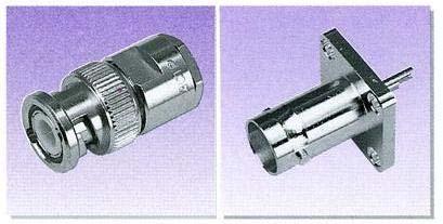
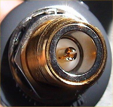
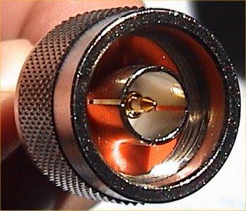
25 Section 5 Antennas and Transmission Lines There are two basic types of feedline. These are coaxial and parallel. Coaxial cable used in radio is unbalanced and is usually 50 ohm impedance Parallel line is balanced transmission line usually 300 or 600 ohm impedance Impedance can be considered as resistance to AC 8 September 2008 TrainSafe Australia 25

26 Section 5 Antennas and Transmission Lines 8 September 2008 TrainSafe Australia 26
27 Section 5 Antennas and Transmission Lines The balun is a type of transformer that can connect a balanced anced antenna to an unbalanced transmission line The balun can also be used to match impedances of transmission lines and antennas 8 September 2008 TrainSafe Australia 27
28 Section 5 Antennas and Transmission Lines The antenna (aerial) couples power from the transmitter to the space around the antenna The antenna radiates an electromagnetic wave by converting electrical signals to radio waves and vice versa The antenna should be resonant at the frequency to be transmitted/received The antenna that radiates well also receives well Antenna are affected by their height above ground and proximity to buildings, trees etc 8 September 2008 TrainSafe Australia 28
29 Section 5 Antennas and Transmission Lines The electromagnetic wave radiated from an antenna is made up of electric lines of force and magnetic lines of force Generally the orientation of the antenna with respect to the ground will indicate the polarisation Generally vertical antennas produce vertically polarised signals and horizontal antennas produce horizontally polarised signals Transmitter and receiver antenna should be the same polarisation for best results 8 September 2008 TrainSafe Australia 29
30 Section 5 Antennas and Transmission Lines The dipole is a half wavelength long and fed at the centre This is a broadside antenna (bi-directional) 8 September 2008 TrainSafe Australia 30
31 Section 5 Antennas and Transmission Lines The quarter wave antenna is the shortest of the full size antennas The driven element is a quarter wavelength long The inner of the coaxial cable is connected to the driven element and the braid connected to the ground plane 8 September 2008 TrainSafe Australia 31
32 Section 5 Antennas and Transmission Lines The folded dipole has the characteristic of being a broad band antenna Fed with 300 ohm TV ribbon 8 September 2008 TrainSafe Australia 32
33 Section 5 Antennas and A Yagi antenna is unidirectional and sends signals and receives signals in the direction the antenna is pointed. Transmission Line 8 September 2008 TrainSafe Australia 33
34 Section 5 Antennas and Transmission Line Antennas such as Yagi s s have gain, and are unidirectional. This means the electromagnetic wave is concentrated into one direction Gain of antennas is measured in decibels The directivity of antennas has a similar effect as using a higher powered transmitter The effective radiated power (ERP) of the transmitting system is increased 8 September 2008 TrainSafe Australia 34

35 Section 5 Antennas and Transmission Lines End fed antennas are usually fed with open wire transmission line and require an antenna tuning unit to match the antenna to the output of the transmitter. 8 September 2008 TrainSafe Australia 35
36 Section 5 Antennas and Transmission Lines Antenna Schematics 8 September 2008 TrainSafe Australia 36
37 Section 5 Antennas and Transmission Lines Antenna Schematics 8 September 2008 TrainSafe Australia 37
38 Section 5 Antennas and Transmission Lines Antenna impedance is measured in ohms Impedance can be considered AC resistance Most modern transmitting equipment has an output impedance of 50 or 75 ohms The output impedance of the transmitter should be matched (have the same impedance) as the transmission line and the antenna. Mismatched transmitter outputs, transmission line and antenna will cause power to be reflected back and forth along the transmission line The reflected wave is called a standing wave 8 September 2008 TrainSafe Australia 38
39 Section 5 Antennas and Transmission Lines A standing wave ratio (SWR) meter is used to measure how well the antenna system is matched. SWR meter is connected between the output of the transmitter and the antenna SWR should be checked each time you change frequency Checking the SWR on a transmission line using a SWR meter is a component of the practical for the Foundation Licence 8 September 2008 TrainSafe Australia 39
40 Section 5 Antennas and Transmission Lines Checking SWR allows for the adjustment of your antenna to bring the antenna closer to resonance by lengthening or shortening the antenna An SWR of more than 2:1 is likely to indicate a fault in the antenna system A good SWR on an antenna system is 1.5:1 or less An SWR greater than 1.5:1 may indicate the antenna needs tuning or a fault condition is developing 8 September 2008 TrainSafe Australia 40
41 Section 5 Antennas and Transmission Line An Antenna Tuning Unit (ATU) sometimes called a Transmatch can be used to provide the correct operating impedance for the transmitter. The ATU tunes the antenna system allowing operation on multiple bands using the one antenna Adjusting the ATU is not a requirement for the practical component of the Foundation Licence but knowing its purpose and location between the transmitter output and the antenna is a requirement 8 September 2008 TrainSafe Australia 41
42 Section 5 Antennas and Transmission Line 8 September 2008 TrainSafe Australia 42
43 Section 5 Antennas and Transmission Line A dummy load is a resistor typically the same output impedance as the transmitter ie 50 ohms The dummy load allows the transmitter to be tested with minimal radiation ie not tested on air via the aerial. The dummy load also allows the output power of the transmitter to be adjusted. 8 September 2008 TrainSafe Australia 43
44 Section 5 Antennas and Transmission Line The power for SSB is 10 watts PEP. For CW, FM and AM average power is not to exceed 10 watts Some power meters can be very inaccurate. Care must be taken in the selection of a power meter to measure output power. 8 September 2008 TrainSafe Australia 44
45 Section 5 Antennas and Transmission Line The purpose of an antenna is to: A. Let people know you are a radio amateur B. Provide a convenient place for birds to land C. Allow balanced transmission lines to be used D. Convert electrical signals into radio waves and visa versa. 8 September 2008 TrainSafe Australia 45
46 Section 5 Antennas and Transmission Line The longer the antenna: A. The higher the frequency of operation B. The lower the frequency of operation C. The better the antenna will work D. The more vertical polarisation will be obtained 8 September 2008 TrainSafe Australia 46
47 Section 5 Antennas and Transmission Line The reason the antenna and transmission line are matched in impedance to the transmitter output is to: A. Increase the SWR B. Eliminate the use of a dummy load C. Keep SWR to a minimum D. Keep the transmitted power to 10 watts. 8 September 2008 TrainSafe Australia 47
48 Section 5 Antennas and Transmission Line An antenna with a 3 db gain operating with at 10 watt transmitter will result in and effective radiated power (ERP) of: A. 3 watts B. 10 watts C. 20 watts D. 30 watts 8 September 2008 TrainSafe Australia 48

49 Section 6 Propagation 8 September 2008 TrainSafe Australia 49
50 Section 6 Propagation Radio waves are electromagnetic waves How these waves travel from the transmitting antenna to the receiving antenna is called propagation Radio waves travel in straight lines although they can be reflected, refracted or diffracted The further the radio wave gets from the transmitting antenna the weaker it becomes Any time a radio wave travels through anything other than free Space it will travel slower and lose strength 8 September 2008 TrainSafe Australia 50
51 Section 6 Propagation The height of the ionospheric layers is approximate The sun ionises or charges the air particles When radio waves hit the ionosphere they can be bent back to earth The bending is dependent on the layer, its density and the frequency of operation 8 September 2008 TrainSafe Australia 51

52 Section 6 Propagation The ionosphere refracts the radio wave The amount of refraction is dependent on: Sun spot activity Time of day The season The ionosphere is reliant on ultraviolet radiation from the sun Sunspots are in an 11 year cycle 8 September 2008 TrainSafe Australia 52
53 Section 6 Propagation A signal travelling from the transmitter to the receiver via two paths can cause multipath fading Selective fading occurs when the frequency components that make up the signal are refracted by different amounts 8 September 2008 TrainSafe Australia 53
54 Section 6 Propagation VHF, UHF and frequencies above UHF are dependent on an almost clear line of sight path from transmitter to receiver VHF and UHF are generally obstructed by hills and other large structures VHF and UHF signals can be bent or diffracted over some obstacles Temperature changes in the troposphere results in ducts that can cause VHF and UHF signals to be propagated over long distances 8 September 2008 TrainSafe Australia 54


55 Section 6 Propagation 8 September 2008 TrainSafe Australia 55
56 Section 6 Propagation As a radio wave is radiated from the antenna. As the wave travels further it becomes: A. Stronger B. Weaker C. Ionised D. Ducted 8 September 2008 TrainSafe Australia 56
57 Section 6 Propagation Long distance HF propagation is a result of: A. Ground wave B. Knife edge diffraction C. Tropospheric ducting D. Ionospheric refraction 8 September 2008 TrainSafe Australia 57
58 Section 6 Propagation VHF and UHF signals can be obstructed by: A. Large obstacles B. Transmission during night time C. Strong north winds D. Transmission over water 8 September 2008 TrainSafe Australia 58

59 Section 7 Interference 8 September 2008 TrainSafe Australia 59
60 Section 7 Interference Interference can generally be resolved by introducing technical solutions, however these can be complex and a qualified person should be sought to resolve these problems. Electronic equipment can operate within an electromagnetic field without interference. This is called Electromagnetic Compatibility (EMC) or radio frequency immunity 8 September 2008 TrainSafe Australia 60
61 Section 7 Interference An amateur station must not cause harmful interference to radio communications including: Other users Other services EMC issues are likely to cause neighbourhood disputes. To resolve a dispute: Discuss the problem with the person concerned, obtain dates and times of interference Try and identify the source of interference Seek advice and where necessary involve the ACMA It may be necessary to shut down your station for a time to identify the interference source but this is not mandatory 8 September 2008 TrainSafe Australia 61
62 Section 7 Interference There are many sources of potential RF noise generation that can interfere with broadcast radio and television receivers. These sources of man made noise include: Power tools Computers Arc Welders Power lines etc 8 September 2008 TrainSafe Australia 62
63 Section 7 Interference Interference can be caused to: Telephones mobile and fixed Television Radio reception Audio equipment Computers Vehicle electronic equipment Blasting devices 8 September 2008 TrainSafe Australia 63

64 Section 7 Interference There are sources of natural noise that can cause interference such as lightning, electrostatic build-up up etc. Amateur stations can cause interference to other radio communication services and television services. The cause of the interference from an amateur station is often as a result of incorrect operation of amateur transmitting equipment 8 September 2008 TrainSafe Australia 64
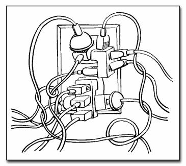
65 Section 7 Interference Potential reasons for interference from an amateur station is: Over modulation -- excessive microphone gain Incorrectly tuned antennas high SWR Breakthrough on FM or SSB close proximity of transmit antenna to receiving antenna Mains fed interference signals fed by the 240 volt mains supply 8 September 2008 TrainSafe Australia 65
66 Section 7 Interference Interference as a result of EMC issues is dependent on: Transmitted power Frequency of operation Type of emission from the transmitter ie AM, SSB, FM etc Distance the transmitter is from the affected equipment selection and location of antennas can significantly reduce the likelihood of interference. 8 September 2008 TrainSafe Australia 66
67 Section 7 Interference Filters can be used to reduce the likelihood of interference Other filters can be used in the power supply or interconnections between the equipment Filters must be fitted as close to the affected device as possible 8 September 2008 TrainSafe Australia 67


68 Section 7 Interference Ferrite rods with wire wound onto them can be used to make effective RF filters These filters are sometimes call coils or chokes 8 September 2008 TrainSafe Australia 68


69 Section 7 Interference Toroids can also be used as RF filters For the practical you will be required to make an RF filter using a toroid or a ferrite rod The RF is blocked by the filter 8 September 2008 TrainSafe Australia 69
70 Section 7 Interference An RF earth connection in an amateur station is to provide a path to minimise RF ground currents entering the mains earth system and causing interference Note the earth symbol RF Earth Power Supply Power Supply 240v Mains Mains Earth 8 September 2008 TrainSafe Australia 70
71 Section 7 Interference EMC problems are dependent on four factors; transmitted power, frequency and type of emission the fourth is: A. Brand of radio transmitter B. Weather C. Distance from the affected equipment D. Sun spot cycle 8 September 2008 TrainSafe Australia 71
72 Section 7 Interference One way interference can be fed into nearby electronic equipment via: A. The 240 volt mains B. Moist atmosphere C. PVC gas pipes D. RF chokes wound on toroids 8 September 2008 TrainSafe Australia 72
73 Section 7 Interference Interference resulting in EMC problems can be minimised by: A. Only using dipoles B. Using vertically polarised antennas C. Careful selection and locating of antennas D. Only operating from a base station 8 September 2008 TrainSafe Australia 73

74 Section 8 Operating Practices and Procedures This is the practical section and will be covered by your you instructor where you will be required to compete practical exercises. See practical assessment checklist 8 September 2008 TrainSafe Australia 74


75 Section 9 Safety 8 September 2008 TrainSafe Australia 75
76 Section 9 Safety The dangers in amateur radio include: High voltages High currents Electromagnetic fields High sound levels Working at heights Working with chemicals The Foundation licence does not permit modification to your transmitting equipment. Foundation licence transmitting equipment must be commercially manufactured. 8 September 2008 TrainSafe Australia 76

77 Electrical safety 12mA of current can kill 240v mains can provide the voltage and current to electrocute a person Vacuum tube equipment will have high voltages present Section 9 Safety 8 September 2008 TrainSafe Australia 77
78 Section 9 Safety Always treat the circuit as if it is live Never remove the covers from any equipment Beware of old equipment, it may not be up to current safety standards Look up and live when installing antennas Never remove an earth from a piece of equipment Always replace fuses with exactly the same type and rating of fuse 8 September 2008 TrainSafe Australia 78
79 Section 9 Safety Protective Earth The Australian 240 volt mains system has an earth (ground) to protect against electric shock, short circuits and faults. The earth wire is usually green/yellow or green in some older installations. The protective earth shall never be removed other than by a qualified electrician 8 September 2008 TrainSafe Australia 79
80 Section 9 Safety Power supplies have a protective earth via a standard 3 pin plug Some power supplies such as plug packs are double insulated and the earth pin is not connected Never connect earths to gas pipes 8 September 2008 TrainSafe Australia 80

81 Section 9 Safety Switch Off Or Remove From The Power 8 September 2008 TrainSafe Australia 81
82 Electric Shock Section 9 Safety Check for danger hazards, risks, safety Responsive if not call 000 Open Airway look for signs of life Give 2 initial breaths Give 30 chest compressions then 2 breaths Defibrillate as soon as possible Continue CPR until qualified person arrives or life signs return Australian Resuscitation Council 8 September 2008 TrainSafe Australia 82
83 Section 9 Safety Fuses Fuses are to protect from high currents Fuses have a predetermined current melt and open the circuit High currents can burn Replace fuses with same type and current rating 8 September 2008 TrainSafe Australia 83
84 Section 9 Safety Earth leakage breakers are sensitive to fault conditions and will trip Most often installed in switchboards Approved mains operated appliances in Australia will have a manufacturers label All states have regulations for maintenance of mains operated equipment and the requirements in relation to the qualifications of those who can work on such equipment. 8 September 2008 TrainSafe Australia 84
85 Section 9 Safety Batteries Some batteries have toxic or corrosive chemicals or produce gases Never short circuit a battery Never dispose of a battery in a fire Use protective fuses with batteries Children should not play with batteries 8 September 2008 TrainSafe Australia 85
86 Section 9 Safety Radiation Safety Electromagnetic radiation may be harmful if concentrated into a narrow beam of very high power Electromagnetic radiation may burn or heat parts of the human body or organs Keep distance between you and electromagnetic radiation 8 September 2008 TrainSafe Australia 86
87 Section 9 Safety Other safety issues: Slips trips and falls Lightning Headphones and loud tones Voltages and currents on antennas RF earthing 8 September 2008 TrainSafe Australia 87
88 Section 9 Safety Fuses are placed in circuits to protect against: A. High currents B. High voltage C. High resistance D. High frequency 8 September 2008 TrainSafe Australia 88
89 Section 9 Safety Batteries should be disposed of correctly because of the environmental issues the chemicals in them can cause. Batteries can also: A. Produce electromagnetic radiation B. Go flat very quickly if unused C. Make loud noises D. Explode or emit fumes if punctured 8 September 2008 TrainSafe Australia 89
90 Section 9 Safety Protective mains earths: A. Should be removed during fault finding B. Are not necessary in amateur radio stations C. Can only be removed or replaced by qualified persons D. Are always represented by a purple wire 8 September 2008 TrainSafe Australia 90
91 IRLP 8 September 2008 TrainSafe Australia 91
92 Continuous Tone Coded Squelch System (CTCSS) This system is designed to reduce annoying signals and will assist in masking co-channel channel interference A tone is transmitted each time the press to talk button is pressed that is detected in the receiver and allows the mute (or squelch) to open. The transmitted tone is in the 67 to 257Hz range and often referred to as a sub- audible tone 8 September 2008 TrainSafe Australia 92
93 Duel Tone Multiple Frequency (DTMF) DTMF is used for telephone signaling over a medium such as a telephone line or radio link DTMF is the signal produced by your mobile phone keypad Two voice frequency tones of different frequencies are transmitted simultaneously Often used to switch on or off and control remote equipment. 8 September 2008 TrainSafe Australia 93

94 Repeater Operation 8 September 2008 TrainSafe Australia 94
The Amateur Licence (amateur foundation station) [the Foundation Amateur Licence] may be obtained by persons
![The Amateur Licence (amateur foundation station) [the Foundation Amateur Licence] may be obtained by persons](/thumbs/96/129175697.jpg "The Amateur Licence (amateur foundation station) [the Foundation Amateur Licence] may be obtained by persons") V9 Foundation Syllabus and Examination. The Amateur Licence (amateur foundation station) [the Foundation Amateur Licence] may be obtained by persons The Foundation Amateur Licence is considered to be the
V9 Foundation Syllabus and Examination. The Amateur Licence (amateur foundation station) [the Foundation Amateur Licence] may be obtained by persons The Foundation Amateur Licence is considered to be the
Assessment Objectives. Syllabus. Amateur Operator s Certificate of Proficiency (Foundation) Syllabus and Examination.
 Syllabus and Examination.") V9 Amateur Operator s Certificate of Proficiency (Foundation) Syllabus and Examination. The Amateur Licence (amateur foundation station) [the Foundation Amateur Licence] may be obtained by persons holding
V9 Amateur Operator s Certificate of Proficiency (Foundation) Syllabus and Examination. The Amateur Licence (amateur foundation station) [the Foundation Amateur Licence] may be obtained by persons holding
Definitions of Technical Terms
 Definitions of Technical Terms Terms Ammeter Amperes, Amps Band Capacitor Carrier Squelch Diode Dipole Definitions How is an ammeter usually connected = In series with the circuit What instrument is used
Technician Licensing Class. Lesson 4. presented by the Arlington Radio Public Service Club Arlington County, Virginia
 Technician Licensing Class Lesson 4 presented by the Arlington Radio Public Service Club Arlington County, Virginia 1 Quiz Sub elements T6 & T7 2 Good Engineering Practice Sub element T8 3 A Basic Station
FCC Technician License Course
 FCC Technician License Course 2014-2018 FCC Element 2 Technician Class Question Pool Presented by: Tamiami Amateur Radio Club (TARC) WELCOME To the third of 4, 3-hour classes presented by TARC to prepare
Technician License Course Chapter 4. Lesson Plan Module 9 Antenna Fundamentals, Feed Lines & SWR
 Technician License Course Chapter 4 Lesson Plan Module 9 Antenna Fundamentals, Feed Lines & SWR The Antenna System Antenna: Transforms current into radio waves (transmit) and vice versa (receive). Feed
Milton Keynes Amateur Radio Society (MKARS)
") Milton Keynes Amateur Radio Society (MKARS) Intermediate Licence Course Feeders Antennas Matching (Worksheets 31, 32 & 33) MKARS Intermediate Licence Course - Worksheet 31 32 33 Antennas Feeders Matching
Milton Keynes Amateur Radio Society (MKARS) Intermediate Licence Course Feeders Antennas Matching (Worksheets 31, 32 & 33) MKARS Intermediate Licence Course - Worksheet 31 32 33 Antennas Feeders Matching
Antennas and Propagation Chapters T4, G7, G8 Antenna Fundamentals, More Antenna Types, Feed lines and Measurements, Propagation
 Antennas and Propagation Chapters T4, G7, G8 Antenna Fundamentals, More Antenna Types, Feed lines and Measurements, Propagation =============================================================== Antenna Fundamentals
Operating Station Equipment
 Amateur Radio License Class Operating Station Equipment Presented by Steve Gallafent October 3, 2007 Operating Station Equipment Modulation Modulation is the process of adding information to a radio signal
Technician Licensing Class. Antennas
 Technician Licensing Class Antennas Antennas A simple dipole mounted so the conductor is parallel to the Earth's surface is a horizontally polarized antenna. T9A3 Polarization is referenced to the Earth
Amateur Radio Examination EXAMINATION PAPER No. 275 MARKER S COPY
 01-6-(d) An Amateur Station is quoted in the regulations as a station: a for training new radio operators b using amateur equipment for commercial purposes c for public emergency purposes d in the Amateur
Technician License. Course
 Technician License Course Technician License Course Chapter 4 Lesson Plan Module - 9 Antenna Fundamentals Feed Lines & SWR The Antenna System The Antenna System Antenna: Transforms current into radio waves
Amateur radio syllabus - Foundation level
 13 August 2018 Page 1 of 18 Section 1 Licensing conditions and station identification 1A 1B 1A1 1A2 1A3 1A4 1A5 1B1 1 1 1 1 2 3 Nature of amateur radio, types of licence and call signs Recall that the
4/18/2012. Supplement T3. 3 Exam Questions, 3 Groups. Amateur Radio Technician Class
 Amateur Radio Technician Class Element 2 Course Presentation ti ELEMENT 2 SUB-ELEMENTS Technician Licensing Class Supplement T3 Radio Wave Characteristics 3 Exam Questions, 3 Groups T1 - FCC Rules, descriptions
4 Antennas as an essential part of any radio station
 4 Antennas as an essential part of any radio station 4.1 Choosing an antenna Communicators quickly learn two antenna truths: Any antenna is better than no antenna. Time, effort and money invested in the
Intermediate Course (5) Antennas and Feeders
 Antennas and Feeders") Intermediate Course (5) Antennas and Feeders 1 System Transmitter 50 Ohms Output Standing Wave Ratio Meter Antenna Matching Unit Feeder Antenna Receiver 2 Feeders Feeder types: Coaxial, Twin Conductors
Intermediate Course (5) Antennas and Feeders 1 System Transmitter 50 Ohms Output Standing Wave Ratio Meter Antenna Matching Unit Feeder Antenna Receiver 2 Feeders Feeder types: Coaxial, Twin Conductors
Amateur Radio License. Propagation and Antennas
 Amateur Radio License Propagation and Antennas Todays Topics Propagation Antennas Propagation Modes Ground wave Low HF and below, ground acts as waveguide Line-of-Sight (LOS) VHF and above, radio waves
4/29/2012. General Class Element 3 Course Presentation. Ant Antennas as. Subelement G9. 4 Exam Questions, 4 Groups
 General Class Element 3 Course Presentation ti ELEMENT 3 SUB ELEMENTS General Licensing Class Subelement G9 Antennas and Feedlines 4 Exam Questions, 4 Groups G1 Commission s Rules G2 Operating Procedures
Amateur Radio Examination EXAMINATION PAPER No. 276 MARKER S COPY
 01-3-(a) The Amateur Service in New Zealand is administered through this prime document: a the New Zealand Radiocommunications Regulations b the Broadcasting Act c the Telecommunications Act d the Radio
Technician License Course Chapter 2 Radio and Electronics Fundamentals. PHYS 401 Spring 2009 P. Reiff, Rice University
 Technician License Course Chapter 2 Radio and Electronics Fundamentals PHYS 401 Spring 2009 P. Reiff, Rice University Basic Station Organization Station Equipment Receiver Transmitter Antenna Power Supply
Technician Licensing Class T9
 Technician Licensing Class T9 Amateur Radio Course Monroe EMS Building Monroe, Utah January 11/18, 2014 January 22, 2014 Testing Session Valid dates: July 1, 2010 June 30, 2014 Amateur Radio Technician
Antenna Design for FM-02
 Antenna Design for FM-02 I recently received my FM-02 FM transmitter which I purchased from WLC. I researched the forum on what antennas where being used by the DIY community and found a nice write-up
Amateur Radio Examination EXAMINATION PAPER No. 272 CANDIDATE S COPY
 01-9 The holder of a General Amateur Operator Certificate of Competency may: a retransmit public broadcasts b transmit in bands allocated to the Amateur Service c repair radio equipment for profit d transmit
Radio Merit Badge Boy Scouts of America
 Radio Merit Badge Boy Scouts of America Module 2 Electronics, Safety & Careers BSA National Radio Scouting Committee2012 Class Format Three modules any order Module 1 Intro To Radio Module 2 Electronic
MFJ-949E. tuner antenowy skrzynka antenowa. Instrukcja obsługi. importer:
 Instrukcja obsługi MFJ-949E tuner antenowy skrzynka antenowa importer: PRO-FIT Centrum Radiokomunikacji InRadio ul. Puszkina 80 92-516 Łódź tel: 42 649 28 28 e-mail: biuro@inradio.pl www.inradio.pl MFJ-949E
Lesson 9: Base Stations
 Lesson 9: Base Stations Preparation for Amateur Radio Technician Class Exam Topics Home Stations Basic Station Layout RTTY and Data Communications Station Accessories Wavelengths Feed Lines Impedance-matching
Amateur Wireless Station Operators License Exam
 Amateur Wireless Station Operators License Exam Study material 2017 South India Amateur Radio Society, Chennai CHAPTER 5 1 Chapter 5 Amateur Wireless Station Operators License Exam Study Material Chapter
4/25/2012. Supplement T9. 2 Exam Questions, 2 Groups. Amateur Radio Technician Class T9A: T9A: T9A: T9A:
 Amateur Radio Technician Class Element 2 Course Presentation ti ELEMENT 2 SUB-ELEMENTS Technician Licensing Class Supplement T9 Antennas, Feedlines 2 Exam Questions, 2 Groups T1 - FCC Rules, descriptions
Results for sample general2015 test paper
 1 / 8 2016/09/22 15:51 Your answers are marked like this: A. You got this question right, this is your correct answer. A. You got this question wrong, this is your incorrect answer. A. You got this question
MFJ-969 Versa Tuner II Instruction Manual
 MFJ-969 Versa Tuner II Instruction Manual General Information The MFJ-969 is a 300 watt RF output power antenna tuner that will match any transmitter or transceiver to virtually any antenna. Peak or average
Amateur Radio Examination EXAMINATION PAPER No. 260 MARKER S COPY
 01-7-(a) An authorised officer from the Ministry of Business, Innovation & Employment can inspect a General Amateur Operator's Certificate of Competency: a at any time b during business hours c at any
CHAPTER 8 ANTENNAS 1
 CHAPTER 8 ANTENNAS 1 2 Antennas A good antenna works A bad antenna is a waste of time & money Antenna systems can be very inexpensive and simple They can also be very expensive 3 Antenna Considerations
Half-Wave Dipole. Radiation Resistance. Antenna Efficiency
 Antennas Simple Antennas Isotropic radiator is the simplest antenna mathematically Radiates all the power supplied to it, equally in all directions Theoretical only, can t be built Useful as a reference:
Technician License. Course
 Technician License Course Technician License Course Chapter 4 Lesson Plan Module - 10 Practical Antennas The Dipole Most basic antenna The Dipole Most basic antenna The Dipole Total length is ½ wavelength
Department of Examination, Sri Lanka
 Department of Examination, Sri Lanka EXAMINATION FOR THE AMATEUR RADIO OPERATORS CERTIFICATE OF PROFICIENCY ISSUED BY THE DIRECTOR GENERAL OF TELECOMMUNICATION OF SRI LANKA 2000 (GENERAL CLASS) Answer
ANTENNAS. I will mostly be talking about transmission. Keep in mind though, whatever is said about transmission is true of reception.
 Reading 37 Ron Bertrand VK2DQ http://www.radioelectronicschool.com ANTENNAS The purpose of an antenna is to receive and/or transmit electromagnetic radiation. When the antenna is not connected directly
MFJ-219/219N 440 MHz UHF SWR Analyzer TABLE OF CONTENTS
 MFJ-219/219N 440 MHz UHF SWR Analyzer TABLE OF CONTENTS Introduction...2 Powering The MFJ-219/219N...3 Battery Installation...3 Operation Of The MFJ-219/219N...4 SWR and the MFJ-219/219N...4 Measuring
Amateur Radio Examination Intermediate Level
 Amateur Radio Examination Intermediate Level Candidate: Candidate DoB: Centre: Exam Date: This paper consists of 45 questions Time Allowed: 1 hour 25 minutes. Candidate Declaration. I confirm that this
SUBELEMENT T4. Amateur radio practices and station set up. 2 Exam Questions - 2 Groups
 SUBELEMENT T4 Amateur radio practices and station set up 2 Exam Questions - 2 Groups 1 T4A Station setup: connecting microphones; reducing unwanted emissions; power source; connecting a computer; RF grounding;
CHAPTER 9 HIGH FREQUENCY RADIO OPERATION CHAPTER
 SECTION 2 ESTABLISHMENT, MAINTENANCE AND OPERATION OF COMMUNICATION SYSTEMS AND EQUIPMENT CHAPTER 9 HIGH FREQUENCY RADIO OPERATION CHAPTER 9 9.1 COMPLEXITIES AND VARIABLES The operation of High Frequency
Technician License Course Chapter 4
 Technician License Course Chapter 4 Propagation, Basic Antennas, Feed lines & SWR K0NK 26 Jan 18 The Antenna System Antenna: Facilitates the sending of your signal to some distant station. Feed line: Connects
D. Frequency. C. 1,500 milliamperes. A khz. C. One thousand volts T5A12
 T5A12 What term describes the number of times per second that an alternating current reverses direction? A. Pulse rate B. Speed C. Wavelength D. Frequency T5A12 D. Frequency ARRL Tech Manual: Page 2-1
Introduction. Understanding Power Ratings. Peak Reading SWR/Wattmeter
 Introduction The MFJ-962D is a "T" network roller inductor tuner with built-in antenna switching, RF power and SWR metering and a 1:1 balun. The largest amplifiers that can safely be used include the Heathkit
1997 MFJ ENTERPRISES, INC.
 INSTRUCTION MANUAL CAUTION: Read All Instructions Before Operating Equipment MFJ ENTERPRISES, INC. 300 Industrial Park Road Starkville, MS 39759 USA Tel: 601-323-5869 Fax: 601-323-6551 VERSION 6C COPYRIGHT
WHY YOU NEED A CURRENT BALUN
 HF OPERATORS WHY YOU NEED A CURRENT BALUN by John White VA7JW NSARC HF Operators 1 What is a Balun? A BALUN is a device typically inserted at the feed point of a dipole-like antenna wire dipoles, Yagi
Lesson 11: Antennas. Copyright Winters Version 1.0. Preparation for Amateur Radio Technician Class Exam
 Lesson 11: Antennas Preparation for Amateur Radio Technician Class Exam Topics Antenna ½ wave Dipole antenna ¼ wave Vertical antenna Antenna polarization Antenna location Beam antennas Test Equipment Exam
MFJ Balanced Line Tuner
 MFJ Balanced Line Tuner Introduction The MFJ-974H balanced line antenna tuner is a fully balanced true balanced line antenna tuner, providing superb current balance throughout a very wide matching range
Central Electronics Model 600L Linear Amplifier
 INTRODUCTION This manual has been reproduced by James Lawrence, NA5RC, a 600L owner. Text no longer applicable such as insurance claim with the carrier has been deleted. Some capitalization and grammar
T5A05 (A) What is the electrical term for the electromotive force (EMF) that causes electron flow?
 What is the electrical term for the electromotive force (EMF) that causes electron flow?") T5A05 (A) What is the electrical term for the electromotive force (EMF) that causes electron flow? A. Voltage B. Ampere-hours C. Capacitance D. Inductance No Nonsense Technician License Study Guide Question
T5A05 (A) What is the electrical term for the electromotive force (EMF) that causes electron flow? A. Voltage B. Ampere-hours C. Capacitance D. Inductance No Nonsense Technician License Study Guide Question
Improved Ionospheric Propagation With Polarization Diversity, Using A Dual Feedpoint Cubical Quad Loop
 Improved Ionospheric Propagation With Polarization Diversity, Using A Dual Feedpoint Cubical Quad Loop by George Pritchard - AB2KC ab2kc@optonline.net Introduction This Quad antenna project covers a practical
MFJ-249B HF/VHF SWR ANALYZER
 TABLE OF CONTENTS MFJ-249B... 2 Introduction... 2 Powering The MFJ-249B... 3 Battery Installation... 3 Alkaline Batteries... 3 NiCd Batteries... 4 Power Saving Mode... 4 Operation Of The MFJ-249B...5 SWR
Technician License Course Chapter 4. Lesson Plan Module 10 Practical Antennas
 Technician License Course Chapter 4 Lesson Plan Module 10 Practical Antennas The Dipole Most basic antenna Total length is ½ wavelength (½ λ) Usual construction: Two equal halves of wire, rod, or tubing
Users Manual. 200W HF/50MHz Band Auto Antenna Tuner. Model HC-200AT
 Users Manual 200W HF/50MHz Band Auto Antenna Tuner Model HC-200AT Caution 1. Never remove or open the tuner cover while transmitting. When there is RF in the circuits of the tuner, there will be high voltage
Radio Station Setup and Electrical Principles
 Radio Station Setup and Electrical Principles Covers sections: T4A-T5D Seth Price, N3MRA February 20, 2016 Outline 4.1 Station Setup 4.2 Operating Controls 4.3 Electronic Principles 4.4 Ohm s Law 4.5 Power
PRACTICE. Amateur Radio Operator Certificate Examination. Advanced Qualification
 Amateur Radio Operator ertificate Examination Advanced Qualification 2019-04-03 To pass this exam, you must correctly answer 35 out of 50 questions Exam Number: 115916 1. (A-007-008-002) Why would one
Cray Valley Radio Society. Real Life Wire Antennas
 Cray Valley Radio Society Real Life Wire Antennas 1 The basic dipole The size of an antenna is determined by the wavelength of operation In free space: ~3x10 8 m/s Frequency x Wavelength = Speed of Light,
Amateur Radio Examination Foundation Level
 Amateur Radio Examination Foundation Level Candidate: Candidate DoB: Centre: Exam Date: This paper consists of 26 questions Time Allowed: 55 minutes. Candidate Declaration. I confirm that this is all my
Test Equipment. PHYS 401 Physics of Ham Radio
 Test Equipment Voltmeter - an instrument that is used to measure voltage. It is used in parallel with a circuit to be measured. a series resistor extends the range of the meter. Ammeter - an instrument
14. COMMUNICATION SYSTEM
 14. COMMUNICATION SYSTEM SYNOPSIS : INTRODUCTION 1. The exchange of information between a sender and receiver is called communication. 2. The arrangement of devices to transfere the information is called
MODERN AM BROADCAST STATIONS AM STEREO CQUAM WITH DDS
 MODERN AM BROADCAST STATIONS AM STEREO CQUAM WITH DDS DDS EXCITER OPERATING MANUAL 20W CARRIER - 80W PEP WHAT IS DDS? IT IS THE INITIALS OF THE WORDS DIRECT DIGITAL SYNTHESIZER. THAT MEANS: DIRECT DIGITAL
Microair Avionics Pty Ltd ABN VHF Aerial Installation FAQ
 Pty Ltd ABN 92 091 040 032 P O Box 5532 Airport Drive Bundaberg West Queensland 4670 Australia Phone: Fax: Email: Web: 07 4155 3048 +61 7 4155 3048 07 4155 3049 +61 7 4155 3049 support@microair.com.au
Class Overview. Antenna Fundamentals Repeaters Duplex and Simplex Nets and Frequencies Cool Radio Functions Review
 Class Overview Antenna Fundamentals Repeaters Duplex and Simplex Nets and Frequencies Cool Radio Functions Review Antennas Antennas An antenna is a device used for converting electrical currents into electromagnetic
2. Capacitors of 8µF, 4µF and 2µF are connected in Parallel. What is the effective Capacitance? (a) 1.14µF (b) 14µF (c) 14 F (d) 1.
 1.14µF (b) 14µF (c) 14 F (d) 1.") 1 DEPARTMENT OF EXAMINATION SRI LANKA EXAMINATION FOR THE AMATEUR RADIO OPERATORS CERTIFICATE OF PROFICIENCY ISSUED BY THE DIRECTOR OF TELECOMMUNICATIONS OF SRI LANKA-APRIL 1993 (GENERAL CLASS) Index No.
1 DEPARTMENT OF EXAMINATION SRI LANKA EXAMINATION FOR THE AMATEUR RADIO OPERATORS CERTIFICATE OF PROFICIENCY ISSUED BY THE DIRECTOR OF TELECOMMUNICATIONS OF SRI LANKA-APRIL 1993 (GENERAL CLASS) Index No.
1) Transmission Line Transformer a. First appeared on the scene in 1944 in a paper by George Guanella as a transmission line transformer, the 1:1
 Transmission Line Transformer a. First appeared on the scene in 1944 in a paper by George Guanella as a transmission line transformer, the 1:1") 1) Transmission Line Transformer a. First appeared on the scene in 1944 in a paper by George Guanella as a transmission line transformer, the 1:1 Guanella Balun is the basic building Balun building block.
1) Transmission Line Transformer a. First appeared on the scene in 1944 in a paper by George Guanella as a transmission line transformer, the 1:1 Guanella Balun is the basic building Balun building block.
An Introduction to Radio Frequency Interference
 An Introduction to Radio Frequency Interference Ron Hranac, N0IVN Member, ARRL EMC Committee ARRL Colorado Section Technical Specialist What is RFI? RFI is an abbreviation for radio frequency interference
Optimizing Your Stations Performance
 Optimizing Your Stations Performance A few hints / techniques, recommendations for getting the most RF out to the Antenna from your HF, VHF / UHF station. Tonights Presenters: Doug Theriault NO1D John
SWR myths and mysteries.
 SWR myths and mysteries. By Andrew Barron ZL3DW September 2012 This article will explain some of the often misunderstood facts about antenna SWR at HF and uncover some popular misconceptions. The questions
ANTENNA THEORY WAVE PROPAGATION HF ANTENNAS
 ANTENNA THEORY WAVE PROPAGATION & HF ANTENNAS FREQUENCY SPECTRUM INFORMATION Frequency range American designator below 300 Hz..ELF (extremely Low Frequency) 300-3000 Hz..ILF (Intermediate Low Frequency)
Ham Radio Training. Level 1 Technician Level. Presented by Richard Bosch KJ4WBB
 Ham Radio Training Level 1 Technician Level Presented by Richard Bosch KJ4WBB In this chapter, you ll learn about: What is a radio signal The characteristics of radio signals How modulation adds information
Interference & Suppression Page 59
 INTERFERENCE Interference & Suppression Page 59 Front-End Overload, Cross-Modulation What is meant by receiver overload? Interference caused by strong signals from a nearby transmitter What is one way
Chapter 4. Propagation, Antennas and Feed Lines. Propagation Black magic topic #1. How do radio waves get from point A to point B?
 Chapter 4 Propagation, Antennas and Feed Lines Propagation Black magic topic #1. How do radio waves get from point A to point B? 1 Radio Wave Propagation Normally radio waves travel in a straight line,
Amateur Operator s Certificate of Proficiency (Standard) Syllabus and Examination.
 Syllabus and Examination.") V1.6 Amateur Operator s Certificate of Proficiency (Standard) Syllabus and Examination. The Amateur Licence (amateur standard station) [the Standard Amateur Licence] may be obtained by persons holding
V1.6 Amateur Operator s Certificate of Proficiency (Standard) Syllabus and Examination. The Amateur Licence (amateur standard station) [the Standard Amateur Licence] may be obtained by persons holding
Technician License Course Chapter 2. Lesson Plan Module 2 Radio Signals and Waves
 Technician License Course Chapter 2 Lesson Plan Module 2 Radio Signals and Waves The Basic Radio Station What Happens During Radio Communication? Transmitting (sending a signal): Information (voice, data,
Computer Networks Lecture -4- Transmission Media. Dr. Methaq Talib
 Computer Networks Lecture -4- Transmission Media Dr. Methaq Talib Transmission Media A transmission medium can be broadly defined as anything that can carry information from a source to a destination.
COAXIAL TRANSMISSION LINE COMMON-MODE CURRENT
 COAXIAL TRANSMISSION LINE COMMON-MODE CURRENT Introduction Coaxial transmission lines are popular for their wide frequency bandwidth and high resistance to electromagnetic interference (EMI). Coax cables
1. What is the unit of electromotive force? (a) volt (b) ampere (c) watt (d) ohm. 2. The resonant frequency of a tuned (LRC) circuit is given by
 volt (b) ampere (c) watt (d) ohm. 2. The resonant frequency of a tuned (LRC) circuit is given by") Department of Examinations, Sri Lanka EXAMINATION FOR THE AMATEUR RADIO OPERATORS CERTIFICATE OF PROFICIENCY ISSUED BY THE DIRECTOR GENERAL OF TELECOMMUNICATIONS, SRI LANKA 2004 (NOVICE CLASS) Basic Electricity,
Department of Examinations, Sri Lanka EXAMINATION FOR THE AMATEUR RADIO OPERATORS CERTIFICATE OF PROFICIENCY ISSUED BY THE DIRECTOR GENERAL OF TELECOMMUNICATIONS, SRI LANKA 2004 (NOVICE CLASS) Basic Electricity,
Technician License Course Chapter 3 Types of Radios and Radio Circuits. Module 7
 Technician License Course Chapter 3 Types of Radios and Radio Circuits Module 7 Radio Block Diagrams Radio Circuits can be shown as functional blocks connected together. Knowing the description of common
87.5 TO MHz BAND II 2 WAY 4.8dBi STACKED DIPOLE ANTENNA
 87.5 TO 108.0 MHz BAND II 2 WAY 4.8dBi STACKED DIPOLE ANTENNA 1. INTRODUCTION 3 1.1. GENERAL INFORMATION 3 1.2. UNPACKING AND CHECKING 3 1.3. WARRANTY 3 1.4. USER SAFETY RESPONSIBILITY 4 1.5. INSTALLATION
Antennas and Propagation
 Antennas and Propagation Chapter 5 Introduction An antenna is an electrical conductor or system of conductors Transmission - radiates electromagnetic energy into space Reception - collects electromagnetic
Antenna? What s That? Chet Thayer WA3I
 Antenna? What s That? Chet Thayer WA3I Space: The Final Frontier Empty Space (-Time) Four dimensional region that holds everything Is Permeable : It requires energy to set up a magnetic field within it.
Coming next: Wireless antennas for beginners
 Coming next: Wireless antennas for beginners In other rooms: Logbook of the World (Sussex Suite) SO2R contest operation (Stable Suite) Wires for your wireless: Simple wire antennas for beginners dominic
Trees, vegetation, buildings etc.
 EMC Measurements Test Site Locations Open Area (Field) Test Site Obstruction Free Trees, vegetation, buildings etc. Chamber or Screened Room Smaller Equipments Attenuate external fields (about 100dB) External
CON NEX HP. OWNER'S MANUAL Full Channel AM/FM Amateur Mobile Transceiver TABLE OF CONTENTS TUNING THE ANTENNA FOR OPTIMUM S.W.R..
 TABLE OF CONTENTS PAGE SPECIFICATIONS... 2 INSTALLATION... 3 LOCATION... 3 CON NEX - 4300HP MOUNTING THE RADIO... 3 IGNITION NOISE INTERFERENCE... 4 ANTENNA... 4 TUNING THE ANTENNA FOR OPTIMUM S.W.R..
MFJ-941E Versa Tuner II GENERAL INFORMATION:
 GENERAL INFORMATION: MFJ VERSA TUNER II The MFJ-941E is designed to match virtually any transmitter to any antenna, including dipoles, inverted-vees, verticals, mobile whips, beams, random wires, and others
Antennas and Propagation. Chapter 5
 Antennas and Propagation Chapter 5 Introduction An antenna is an electrical conductor or system of conductors Transmission - radiates electromagnetic energy into space Reception - collects electromagnetic
Television and video engineering
 Television and video engineering Unit-4 Television Receiver systems Objectives: To learn the requirements of TV receiver Study of monochrome and Colour TV receivers. To learn functions of Tuning circuits
One I had narrowed the options down, I installed some wire and started testing.
 Loft & Attic antennas for restricted spaces - M. Ehrenfried G8JNJ I ve recently been looking at designs for an efficient antenna that would fit in a loft. I hoped to find something that would work on with
SOME USES FOR RF1,RF5 and VA1 ANALYSTS. SWR Measurement
 SOME USES FOR RF1,RF5 and VA1 ANALYSTS THE HANDIEST INSTRUMENTS IN DECADES! When you put up an antenna in the the old days, it could be a real struggle. The only way to tell if it was tuned to the right
Lesson 12: Signal Propagation
 Lesson 12: Signal Propagation Preparation for Amateur Radio Technician Class Exam Topics HF Propagation Ground-wave Sky-wave Ionospheric regions VHF/UHF Propagation Line-of-sight Tropospheric Bending and
Table of Contents. MFJ-1778 G5RV Multiband Antenna
 Table of Contents MFJ-1778 G5RV Multiband Antenna Introduction... 1 Theory Of Operation... 1 80 meter band:... 1 40 meter band:... 1 30 meter band:... 2 20 meter band:... 2 17 meter band:... 2 15 meter
ANNEX 6: EXAMINATION SYLLABUS AND REQUIREMENTS FOR A HAREC INTRODUCTION
 RECOMMENDATION T/R 61-02 Page 12 ANNEX 6: EXAMINATION SYLLABUS AND REQUIREMENTS FOR A HAREC INTRODUCTION This syllabus has been produced for the guidance of the administrations so that they may prepare
The G4EGQ RAE COURSE Lesson 9 Transmitters Lesson 8 looked at a simple transmitter exciter comprising of oscillator, buffer and multiplier stages.
 Lesson 8 looked at a simple transmitter exciter comprising of oscillator, buffer and multiplier stages. The power amplifier The output from the exciter is usually very low and it is necessary to amplify
Radio Receivers. Al Penney VO1NO
 Radio Receivers Al Penney VO1NO Role of the Receiver The Antenna must capture the radio wave. The desired frequency must be selected from all the EM waves captured by the antenna. The selected signal is
Chapter 6 Antenna Basics. Dipoles, Ground-planes, and Wires Directional Antennas Feed Lines
 Chapter 6 Antenna Basics Dipoles, Ground-planes, and Wires Directional Antennas Feed Lines Some General Rules Bigger is better. (Most of the time) Higher is better. (Most of the time) Lower SWR is better.
4/30/2012. General Class Element 3 Course Presentation. Practical Circuits. Practical Circuits. Subelement G7. 2 Exam Questions, 2 Groups
 General Class Element 3 Course Presentation ti ELEMENT 3 SUB ELEMENTS General Licensing Class Subelement G7 2 Exam Questions, 2 Groups G1 Commission s Rules G2 Operating Procedures G3 Radio Wave Propagation
Technician License Course Chapter 5. Lesson Plan Module 11 Transmitters, Receivers and Transceivers
 Technician License Course Chapter 5 Lesson Plan Module 11 Transmitters, Receivers and Transceivers Generalized Transceiver Categories Mobile Single Band Dual Band All Band Multimode Handheld (HT) VHF/UHF
Lesson 3: Electronics & Circuits
 Lesson 3: Electronics & Circuits Preparation for Amateur Radio Technician Class Exam Topics Review Ohm s Law Energy & Power Circuits Inductors & Inductance Capacitors & Capacitance Analog vs Digital Exam
Nature of Amateur radio 1.1 Recall that Amateur radio is intended to facilitate hobby radiocommunications.
 V1.6.3 Amateur Operator s Certificate of Proficiency (Advanced) Syllabus and Examination. The Amateur Licence (amateur advanced station) [the Advanced Amateur Licence] may be obtained by persons holding
Module 8 Theory. dbs AM Detector Ring Modulator Receiver Chain. Functional Blocks Parameters. IRTS Region 4
 Module 8 Theory dbs AM Detector Ring Modulator Receiver Chain Functional Blocks Parameters Decibel (db) The term db or decibel is a relative unit of measurement used frequently in electronic communications
CHAPTER - 6 PIN DIODE CONTROL CIRCUITS FOR WIRELESS COMMUNICATIONS SYSTEMS
 CHAPTER - 6 PIN DIODE CONTROL CIRCUITS FOR WIRELESS COMMUNICATIONS SYSTEMS 2 NOTES 3 INTRODUCTION PIN DIODE CONTROL CIRCUITS FOR WIRELESS COMMUNICATIONS SYSTEMS Chapter 6 discusses PIN Control Circuits