HOW I REBUILT MY BLOWN KENWOOD TS-930S
|
|
|
- Adele Theresa Warren
- 5 years ago
- Views:
Transcription

1 HOW I REBUILT MY BLOWN KENWOOD TS-930S (With an Addendum on how to convert the later dual-voltage AVR board rigs to a modern power supply) John Young, W3AFC DISCLAIMER. This paper describes how I rebuilt my Kenwood TS-930S transceiver using an industrial railmount switching power supply. While this has been done by others and it works very well, I recommend reading this paper in its entirety before gutting out your existing power supply, if it works. While I am very happy with my results I can t be held liable if you perform this conversion and are not satisfied. The mods described herein do not require advanced knowledge or skills. All you need is a fine-tip soldering iron and a Digital Multimeter (DMM). Background. The Kenwood TS-930S is a true HAM OP s radio, with a logical control layout and features that make it competitive in contests even against today s radios. When it s working, it s true love. When something goes wrong with mine, I want to toss it out a window. I would say torch it, but I ve already done that by accident. My rig is a first-year production run with a serial number of 3,060,xxx, but this conversion is easy with the later models also (see Appendix). This model seems to suffer from a number of reliability issues as it ages, but the only two areas that I ve experienced trouble with so far are the power supply, and the Power Amplifier (PA). The Problem: I was in the middle of a QSO with a station in Latvia when suddenly the other OP started asking "W3AFC? Are you still there?" Everything seemed normal and even the "On the Air" light was still working. But it wasn't putting out a signal and now Ic and Power were at "zero". However, Vc was right on 28 volts. I shut down and dug in to find the problem. It sounded like a relay wasn't engaging, which led me to RL-3 at the rear underside of the signal board. Diagnostics: My tests with an RF probe showed a little over 3-V P-P of RF at RL-3, and a quick check with my 830 Sugar revealed that a nice clean modulated signal was present at the indicated frequency. But when the 930S transmit was engaged, RL-3 didn t close, so that RF went to the transverter socket on the back. It appeared that a protection circuit was keeping RF from reaching the PA by disabling RL-3. Believing that the relay itself or the coil circuit had failed, I fed the RF through a jumper to the PA but nothing happened. I would soon learn that the circuit is part of transceiver control line TXC, which comes from a 3-pin plug on the PA board near the power leads. The center is 18 volts in, and it feeds that voltage through thermistor TH1 back to the Low Pass Filter (LPF) via the TH line. The TXC line connects to the base of Q9 on the PA, and is part of a transceiver control circuit that is centered on IC1. All of this is becomes obvious if one has a clean copy of the schematic for the PA, which I found in a high-quality User s Manual PDF on Kenwood s web site. Once I had that, I began to suspect the PA, so I turned my attention there. Then, while measuring voltages in the PA, I accidentally touched the 28V B+ at Q7 s collector to ground. I was using a probe with an insulated cover, but somehow it still made contact. The rig's lights dimmed for a second and there was a click like a protection circuit had kicked in, and then everything came back to normal, like nothing had happened. A dummy load was connected and I could hear a strong local QSO coming from the speaker. But before I could give a sigh of relief, two carbon resistors on the AVR board burst into flames and set half the board on fire. I now had TWO problems to deal with.

2 The Power Supply. My first impulse was to look on ebay for a replacement AVR board, and I actually found the exact one for under $100 with shipping. But the OEM power supply was always a major area of concern for me and I began to question the wisdom of sinking money into it. I was so concerned about heat-related issues that I bought a pair of 6-inch home theater amplifier cooling fans that came on the moment I switched on the rig. Heat poured out through those fans. Volumes have already been written about improving the original voltage regulator-based power supply, including white papers by PhD s in Electrical Engineering, so I won t try to expand on that subject. For those who are unfamiliar with the problem, here s what happens: One of the TO-3 regulator transistors opens, and the AVR board feeds 40.5 volts DC instead of 28V to the PA unit. The MRF485 driver transistors are rated at a maximum of 35-volts Emitter-to-collector, so they blow. There goes $50.00 or more in a flash. The 19-volt Zener diode, D5, usually shorts too. There s no point in rebuilding a 30-year old linear power supply like this one when there are modern solutions to this problem that are safer, lighter, and that operate at MUCH lower temperatures. I investigated three different power supplies: - A 28-volt, 300-watt Nao Technologies open-frame switching power supply, - An Acopian 28-volt, 14 amp continuous (392 Watts) Gold Box W28MT14 power supply, and - Two Phoenix Contact Quint models with outputs that are adjustable from 24 to 28.5-volts or more. The two Phoenix Contact supplies are rated at 10 amps continuous at 24 Volts, but they have a boost mode reserve that lets them run up to 15 amps 1. This allows them to produce 360 watts max at 24 volts, which translates to about 12.6 amps at 28.5 volts. I liked the Acopian s continuous rating of 14 amperes at 28 volts and 392 watts, but based on its published dimensions I could not make it fit without relocating the PA. In addition, the Acopian has an AC input range of only VAC versus VAC for the Quint. Since others have installed the Quint with success, I decided to try it. The maximum stated power dissipation of the 930S during transmit is 510 watts, but that figure includes transformer and other losses due to the low efficiency of the original power supply. I reality, the 930S needs about 350 watts, based on the specifications. The PA input power is 250 watts. The receiver by itself uses 80 watts, and although the receiver is muted during transmit, it s still drawing power. So now we re up to 330 watts. If your rig has the built-in antenna tuner, it will draw power also (the exact figure is not stated in the User manual). And then there are the fans to consider. So the Phoenix Quint 10-amp model at 360 watts boost is JUST adequate. Fortunately, the Quint s data sheet states that at ambient temperatures of up to +40 C (104 o F) the boost mode reserve is available continuously. At higher temperatures it is available for around ten minutes. But the PS would not have to provide boost power that long, even in FSK mode. The Owner s manual warns that output power should be reduced by 50% to prevent damage under those conditions. A quick ebay search turned up a couple NOS surplus units for about $70 with shipping. The model I chose is the , shown below. This version has three sets of output terminals, all in parallel, which makes it easier to hook the existing wires in. But I only ended up using two of them, so the other Quint model which has two sets of outputs would work just as well. That model number is According to the published literature, the model is 25 mm thicker than the newer 763 version. Both come with a rail mount on one side, which is easy to remove. 1. Phoenix Contact now makes a 20/26-amp model that will fit in the 930S (see Appendix)

3 IMPORTANT: Some people recommend gutting out everything associated with the old power supply system, including the power relay near the voltage selector switch. That relay feeds 120 or 240 volts up to separate windings on the power transformer. I removed all of that, but then I realized that Kenwood ran very fine wires up to the front panel power switch, since they only need to carry the low current of that relay coil. But now those wires would have to handle enough primary side amps to provide 360 watts output. I felt the need to run heavier wires up to the switch. I m concerned now that the increased load on the main power switch will result in poorer reliability than that relay system. I recommend leaving in the relay system and just using the solid-conductor wires to the transformer primaries that are already in place. You will need to remove the transformer and bracket, filter capacitor assembly, voltage regulators and heatsink, and the AVR board. I used the AVR board to run the fans and front panel meter as you will see later. These can all be lifted out as one big mess with the wires still connecting them together. Set these parts aside for now. The photo below shows my model 763 Quint mounted in my radio. It fits right where the transformer was, with just enough room for the AVR board. At this point, I wanted to reconnect the receiver while I dug into the PA section. I was accustomed to using my 930S with my Swan 700 s when the noise floor at my QTH overloaded the older Swan receivers. I ve experienced a dramatic increase in impulse noise at my shack, so I often use my 930S as a receiver. But I also wanted to see if switch-mode power supply noise would cause interference in the 930s. If it did, I could stop right here before I invested more time and money in this solution. The Phoenix Contact Quint mounted in my TS-930S I took the easy way out by simply connecting the 28-volt B+ output lines from the AVR board to the terminals on the Quint. The original voltage divider system for the sub-voltages worked fine, so after testing it I decided to leave that alone. I connected the heavy black chassis ground lead to the ground terminal on the AC in side of the Quint, which required adding 4-6 inches of #10 stranded wire. I did it that way because with just the receiver in the circuit I noticed a 0.25 volt difference in DC potential between the negative terminals on the DC side of the Quint and chassis ground. I suspected that the DC minus line inside the Quint was designed to float rather than operate at chassis ground. Once the grounded black lead from the PA is connected to a negative terminal on the Quint, those terminals will be forced to chassis ground anyway, so connecting the heavy black lead to the Quint s minus output side would probably not cause a problem. But I decided not to risk it, since everything was working perfectly the way I had it hooked up.


4 Here s a closer look at how I mounted my Quint. I used the transformer mounting bracket, but I turned it 90 degrees so that when I mounted the PS, the air intake and outlet would be in line with the original VR heat sink fan. The older model is almost an inch taller than the one I used so you can t use the transformer bracket as a mount. If you do the power supply will be too high for the top half of the case to fit once you re finished. I used 3M snap lock fasteners to hold the Quint in the bracket so that I can remove it if I have to. If I plan to travel with the rig I ll put a pair of 18-inch plastic zip ties around the ends of the power supply and the bracket to lock it in place. But the snap fastener system is so strong that any impact that would shake the Quint loose would surely cause damage to other parts of the rig as well. You may have to shorten the top cover screw next to the Quint in case it hits. The resistor that creates the voltage drop for the panel meter is mounted to an existing hole for the old filter capacitor housing. I didn t want to drill new holes in the chassis because I was afraid shavings might go somewhere they shouldn t and give me another problem to fix when I switched on the rig. It looks close but there s a half inch of clearance. I drilled new holes in the transformer bracket instead of the chassis for the mounting screws the same reason. The fuse holders are held securely by high strength 3M double-sided foam tape. You could use three or four 1-inch wide strips of that tape to mount the bracket to the chassis instead of drilling and it would never work loose. With everything in place, the rig looks stock from the rear, except you can see the interior of the Quint power supply, and there s no screw in the case above the fan. I put in that case screw back in with a nut to make it look stock.


5 Some HAMs who have performed this modification have removed the parts they need from the AVR board and mounted them on a terminal strip, but I gutted the board, leaving on the connectors for the fans, as well as the two small green inductors for Ic and Vc at the front panel meter. 2 Also, I needed a place to mount a 250-ohm dropping resistor to run the cooling fans at reduced speed when the rig is turned on (red). I had to use wire jumpers to the fan connectors because the foil traces were burned completely off the board. With respect to that resistor, I used a 5-watt wire wound. The PA fan measured 59 ohms cold resistance, and the PS fan 47 ohms. So with the fans wired in series, the total resistance is 356 ohms. With 28 volts, the calculated current is milliamps, which amounts to 2.2 watts dissipation. Once the fans are running, the impedance of the fans will be higher so the dissipation will be even lower. So a 5 watt resistor works fine. This results in a solid airflow without any discernible noise. If you want more flow, you can wire the fans in parallel, which results in 276 ohms, and brings the wattage up to 2.84 watts. In a quiet room, you ll hear the fans, but it s still not intrusive. But with the switching power supply, heat will no longer be an enemy, so I used series for my own rig. NOTE: I also reworked a newer split-voltage board so that owners of post 3,100,xxx model 930 s can use a switching power supply See the Appendix at the end of this paper. My AVR board, ready to reinstall! I put the receiver and digital board circuits on a separate fuse from the PA. The receiver consumes 80 watts at 28.5 volts, which translates to 2.8 amps. A 3-amp slow-blow fuse works perfectly. For the PA, I used a 10-amp slow-blow. I hooked the rig up to a receive antenna and everything was loud and clear, without a trace of harmonics or switching hash. These are industrial-grade power supplies that retail for over $500, so I would expect them to have noise filtration built-in. 2. The two diodes and the disc capacitors actually aren t used here. I left them on the board in case I needed them to achieve proper operation of the front panel meter. But the panel meter works just as it did with the old power supply.

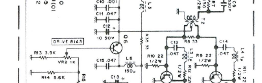
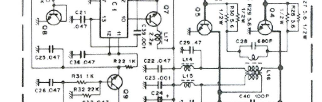
6 The Power Amp: With the receiver back online, it was time to dig into the PA. Nothing appeared burned nor were there any odors. But a run-through with a DMM/diode tester revealed that driver transistor Q2 was shorted, and Q3 was open. The 19-volt Zener diode D5 was also shorted. But the expensive Motorola NRF 422 outputs tested good. WHEW! I ordered replacement MRF485 s from an Eleflow dealer in England. They were $15 each, and shipping was another $15, so I paid $45 for the two. There are cheaper brands out there, but I ve heard they have too much gain which may cause oscillations that destroy the finals. The Eleflows arrived quickly. For D5, I bought a 5-watt version (NTE 3154A) for under $3.00 from Radio Shack to replace the original 1-watter. Installation of the replacement parts was pretty straightforward. The main thing to remember is that the drivers must sit parallel to the bottom of the circuit board, with the top of each transistor flush with the bottom of the PC board. Otherwise, the tabs on the drivers won t lie flat on the heat sink assembly and you may end up frying your new drivers. Look at your old drivers to see how the leads were bent. You don t want to have to bend them more that once or twice, because if one breaks off from fatigue at the body, you re hosed. Remember also not to go overboard when soldering in the drivers. The leads will be very short and the heat will go right to the transistor junctions. Once everything is in place, it s time for some resistance and diode tests before you power up the PA. I used the schematic from Kenwood as a guide. It comes in two sections so I used PhotoStudio to stitch it together as one. A large version is in the APPENDIX section at the end of this paper. Apparently, my rig had been worked on at least once before because someone had already fed thin wires through some of the thru holes, including the emitter and base ferrules at Q2 and Q3. A couple foil traces had been bypassed with wires also. In addition, some of the wire bundles under the signal board were held together with white kitchen ties. I m pretty sure Kenwood didn t put those there.
7 The first thing I noticed after installing everything was that an almost dead short appeared across D5, and worse yet, it appeared across the Emitter-Base leads on both drivers as well. Mine measured 15.3 ohms. However, if you look at the schematic below, you will see why. Q6 s emitter, along with D5, C10, C11, and C12 are connected to the center-tap on the secondary of transformer T2. And the ends of T2 s secondary are connected to the bases of Q2 and Q3. Since the emitters are grounded, and T2 s secondary is grounded on one end through a 22-ohm resistor, the circuit appears to be shorted - but it s not. I checked with a DMM to make sure all of the emitters that are supposed to be grounded were, and those that aren t weren t. I checked and rechecked diodes and other components as well as the shoulder washers on the collector tabs of the drivers and other transistors. I also tested for a diode relationship across the main power input leads to the PA. Finally, I bolted it all back together, hooked up the wiring, connected a dummy load, and turned the rig on. NO SMOKE! That was good. Before powering the rig up I connected my MC-50 microphone, turned off the processor, and turned the mike gain all the way down. I eased the gain up a notch or two and blew gently into the mike, and the power needle on the rig and on my peak reading wattmeter swept up to about 20 watts. I gradually increased the mike gain until the rig was putting out over 100 watts. Time to switch in the antenna!

8 I heard W1AW/7 calling from Oregon, and I called back. They came back to me immediately and gave a 59 report. I told them this was the maiden voyage of my now rebuilt 930S, and they said it sounded great. After a few more contacts, I dove into the SP DX contest that was underway, and everyone said the audio was perfect classic Kenwood. This is my baby, back in the lineup. It works just like before, except now I can put it on the upper level of my shack hutch because it weighs only 28 lbs. The overall weight loss was around 10 lbs. And the rig is balanced and easy to carry. It was left-heavy before due to the location of the power transformer. It runs so much cooler that I could set magazines on top, but you can bet I won t. Now that it s up and cruising again, I ve adjusted the output voltage on the Quint up to 28.5 volts. I started it at 26.5 VDC because I was worried about another blow up. After operating it for a few days, I had to see how often the Quint power supply was entering boost mode when operating at full power, so I pulled the cover and watched while I talked. Although the data sheet from Phoenix Contact states that the Quint can operate in boost mode almost continuously, I wanted to see if it actually was. I was most interested in SSB, but I also tried AM and CW modes. This is what I discovered: On strong SSB voice peaks where the PEP reached 100W or more, the yellow boost light came on! (See photo below) On CW it came on full brightness every time I keyed down. But it stayed dark on AM, probably because AM output is limited to 40W. This proves that the Nao Tech 28-volt, 10.7 amp power supply that I was considering in the beginning would not have had enough power to run this radio. But the Acopian 14-amp supply should have worked perfectly, had it fit.

9 The Yellow BOOST Mode Light on the Quint Power Supply One month later: How does it compare? After a month of almost nightly use with the switching power supply, I have to say I m very happy with the mod. The Quint handles the load easily, and after a full day of contesting or other use, the top of the rig is barely warm. The only part that generates any heat is the resistor bank assembly in front of the Low Pass Filter assembly. I even left my 930S on overnight by accident, and it didn t get warm. UPDATE: Phoenix Contact has a newer model PS that is rated at 20/26 amps, and based on the published dimensions, it will fit in the 930S. It s model number The published dimensions are 130mm long x 125mm wide x 90mm (3.54 in.) high. While this is substantially taller than the model that I used, it s only 5mm higher than the popular that other HAMS have used. That means it will fit in the 930S. At 624 watts, this Quint is stronger than the OEM power supply, so if you push the rig into a high SWR, it won t back down. That might spell disaster for your drivers.
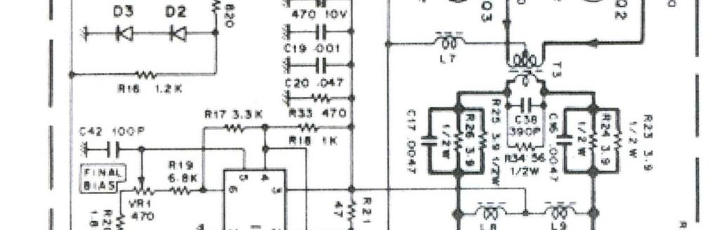
10 APPENDIX I decided to add this section so that I could include additional photos, schematics, and also instructions on how to modify your post 3,100,xxx serial number AVR board to work with the Phoenix Contact or other switching power supply. Rebuilding a TS-930S with the 28.5 & 21.7-volt AVR Board If you have a later model 930S with the dual-output AVR board and you don t feel like re-building the AVR board (or yours is completely fried), ebay sellers offer solutions - small adjustable converter boards that typically reduce 3-40-volts down to volts. There are even some that appear to be scaled-down versions of the Phoenix Quint. Many can handle 4-5 amps without a heat sink. I have to confess, I bought one just to play with. Most cost less than $15. Phoenix Contact also sells a Quint-Series DC-DC converter that has the same 125mm x 130mm length and width as either of the Quint power supplies discussed above. Its depth is 32mm, so if you mount a big Quint directly to the 930S chassis using the 3M snap-lock fastener system, the smaller Quint could sit on top using 3M double-sided tape and you could even line the terminals up so that the two could be removed as a package for service (no, I don t work for 3M). The Phoenix Quint converter handles 5 amps. The part number for it is It lists for $267, but no doubt you could find it on ebay for a lot less. Or, you can do what I did and strip the original AVR board down to the bare essentials, and reuse it. The board that I rebuilt for another HAM (N6BIZ) suffered the same blowup and fire that mine did, but the components that generate the 21.7 volts survived unscathed. A fried Post 3,100,XXX AVR Board. The same two carbon resistors exploded! The strip-down procedure for this board is pretty much the same as with the older AVRs. You just need to leave on Q6 and its associated components, and keep the TO-220 regulator Q3. If you toss the OEM PS heat sink, you will need to mount Q3 to the chassis or some other heat sink, or else it may end up in electronics component heaven.

11 The Dual-Voltage AVR Board schematic with the pertinent circuits highlighted

12 THIS is what your board will look like after it s stripped. Note from the schematic above that the 21.7-volt sub-system is literally stand-alone. It s fed 28-volts DC through the power switch from terminal 28B into pin 1 of the connector, while pin 5 receives 28 volts DC from a separate circuit via diodes D1 and D2. I used jumpers to the 28-volt line from the Quint, and everything works fine. Be sure to leave on the ferrite bead jumper and the green inductors for the panel meter circuit. The three empty spaces for the electrolytic capacitors and their associated foil traces are perfect for distributing power to the remaining circuits, as shown below. NOTE: THE RED WIRE in the picture below is not necessary if you left the orange wire to the 21.7 volt plug intact. On this board, it had been cut so I needed to create a cross-connect.
13 All you have to do is install 28-volt power leads to the plus and minus foils on your AVR board, and connect some jumpers to bring 28-volts o the 21.7-volt sub-regulator, and the green inductor for the Vc circuit. The other one is just mounted on the AVR board. As the schematic shows, it s a feed-through between pins 1 and 2 for the Ic circuit, so you won t be running 28-volts to it. If you use the stock fans as I did, you will need the dropping resistor unless you want them to roar at full speed all the time. I wired mine so that the PA fan blows in against the heat sink, and the PA fan blows out to draw air through the Quint and out of the rig. Here is the later model AVR board, ready to reinstall. Remember to install the regulator transistor using an insulating mica washer or the original rubber pad, and a shoulder washer to insulate the screw. Otherwise, you will short the 28 volt B+ right to ground. A late-model AVR board, ready to reinstall ACKNOWLEDGEMENTS I would like to give special thanks to two HAMS who provided input while I was working on this paper. They are Gary Mankoff (N6BIZ) in California, and Mike Hutchins (ZL1MH) in New Zealand. Gary shipped his toasted Post 3,100,xxx AVR board to me so that I could figure out how to modify the later 930S to work with the Quint power supply. His board is the one you see above. This should be of great value to HAMS who have the later-model 930 s. Mike has three TS-930 s, all with serial numbers under 3,100,xxx. He has already modified one using the Quint model PS that I describe on page two. He reports that his works great also. He plans to modify the second 930S using the procedure described by VK4AMZ, and leave the last rig untouched as a control. When I first started using my rebuilt 930S, I noticed that when driving at full power into a SWR over 2:1, the dial lights dimmed and the voltage dropped. I blamed the Quint. However, Mike tried that with his unmodified 930S, and he had similar results. It turned out to be caused by the ALC circuit. We corresponded at great length while I wrote this paper, and his input has been invaluable.
14
Options for Repairing your Kenwood Power Amplifier Rev. 1/08/2019 (Important note regarding Option 2)
") Options for Repairing your Kenwood Power Amplifier Rev. 1/08/2019 (Important note regarding Option 2) If the power output from your 930S is zero, or close to it and you are certain that the problem is
Options for Repairing your Kenwood Power Amplifier Rev. 1/08/2019 (Important note regarding Option 2) If the power output from your 930S is zero, or close to it and you are certain that the problem is
LEVEL 1 LEVEL 2 Tests 1a & 1b Tests 2a through 5b
 ANATOMY OF A WORKING TS-930S POWER AMPLIFIER Version 1a The purpose of this document is to help HAMs determine whether or not his/her TS-930S RF power amp is in working condition, and if tests indicate
REPAIRING THE RM KL400 LINEAR AMPLIFIER.
 REPAIRING THE RM KL400 LINEAR AMPLIFIER. Les Carpenter G4CNH December 2012 Page 1 of 20 The following is a step by step guide to fixing your KL400 amplifier. Each part will be individually tested up to
Assembly Instructions for the FRB FET FM 70 Watt Amp
 Assembly Instructions for the FRB FET FM 70 Watt Amp 1.) Orient the circuit board with the diagram 2.) Use a narrow chisel tip 25-30 watt soldering iron for assembly 3.) All the small parts are taped onto
Modifying The Heath HA-14 For 6 Meters Greg Chartrand - W7MY 4/22/07
 Introduction The Heathkit HA-14 was one of the few electron tube linear amplifiers intended for mobile use but few were purchased with the 12 volt mobile power supply. Most hams bought the HA-14 for base
Bill of Materials: PWM Stepper Motor Driver PART NO
 PWM Stepper Motor Driver PART NO. 2183816 Control a stepper motor using this circuit and a servo PWM signal from an R/C controller, arduino, or microcontroller. Onboard circuitry limits winding current,
Assembly Instructions for the 1.5 Watt Amplifier Kit
 Assembly Instructions for the 1.5 Watt Amplifier Kit 1.) All of the small parts are attached to a sheet of paper indicating both their value and id. 2.) Leave the parts affixed to the paper until you are
HAMTRONICS LPA 2-25R REPEATER POWER AMPLIFIER: ASSEMBLY, INSTALLATION, & MAINTENANCE
 HAMTRONICS LPA 2-25R REPEATER POWER AMPLIFIER: ASSEMBLY, INSTALLATION, & MAINTENANCE GENERAL INFORMATION. The Power Amplifier is a class C device designed to be installed as an integral part of a transmitter
LA502 Assembly guide Main PCB Resistors - (2)
") LA502 Assembly guide Safety warning The kits are main powered and use potentially lethal voltages. Under no circumstance should someone undertake the realisation of a kit unless he has full knowledge about
LA502 Assembly guide Safety warning The kits are main powered and use potentially lethal voltages. Under no circumstance should someone undertake the realisation of a kit unless he has full knowledge about
KN-Q10 Assembly Manual
 KN-Q10 Assembly Manual Translated by Adam Rong, BD6CR/4 with permission from Ke Shi, BA6BF Edited by Stephen, VK2RH Revision B, Oct 14, 2010 Thank you for purchasing the KN-Q10 4 Band SSB/CW Dual Mode
RadiØKit Μ CW HAM RADIO TRANSCEIVER KIT. Assembly and operating manual
 RadiØKit-120 20Μ CW HAM RADIO TRANSCEIVER KIT Assembly and operating manual Boreiou Ipirou 78 Kolonos Athens- Greece - 10444 Tel: 210.5150527 210.5132673 www.freebytes.com Thank you for buying RadiØKit-1,
Pacific Antenna Easy TR Switch
 Pacific Antenna Easy TR Switch Kit Description The Easy TR Switch is an RF sensing circuit with a double pole double throw relay that can be used to automatically switch an antenna between a separate receiver
PAT-4 POWER SUPPLY ASSEMBLY MANUAL Rev B Version
 PAT-4 POWER SUPPLY ASSEMBLY MANUAL Rev B Version 2013 AkitikA, LLC All rights reserved Revision Bp01 November 3, 2013 Page 1 of 16 Table of Contents Table of Contents... 2 Table of Figures... 2 Section
TS500 Assembly guide. Soldering. TS500 Assembly guide Main PCB 1. Diodes. Document revision 1.2 Last modification : 17/12/16
 TS500 Assembly guide Safety warning The kits are main powered and use potentially lethal voltages. Under no circumstance should someone undertake the realisation of a kit unless he has full knowledge about
SoftRock v6.0 Builder s Notes. May 22, 2006
 SoftRock v6.0 Builder s Notes May 22, 2006 Be sure to use a grounded tip soldering iron in building the v6.0 SoftRock circuit board. The soldering iron needs to have a small tip, (0.05-0.1 inch diameter),
Easy Transmitter. Support ETX_REV5_Manual V2.7 Revised
 Easy Transmitter Introduction The Easy Transmitter kit from qrpkits.com provides a basic, crystal controlled transmitter with VXO tuning to provide a small tuning range around the crystal frequency. It
Ameritron ALS-600 Retrofit ALS-600-LPF Assembly Manual
 Ameritron ALS-600 Retrofit ALS-600-LPF Assembly Manual FEATURES Automatic band change based on TX frequency. PIN diode QSK RX/TX switch. Temperature controlled FAN for quiet operation. RS-232 serial port
Pacific Antenna - Easy TR Switch
 Pacific Antenna - Easy TR Switch Kit Description The Easy TR Switch is an RF sensing switch that can be used to switch an antenna between a receiver and transmitter. It also has a second switched pair
Construction Manual 4m-Linear-Transverter XV4-15
 Construction Manual 4m-Linear-Transverter XV4-15 Holger Eckardt DF2FQ Kirchstockacherstr. 33 D-85662 Hohenbrunn 3207 Technical data exciter frequency: 21.0... 21.5 MHz RF frequency: 70.0.. 70.5 MHz supply
Assembly Instructions
 Assembly Instructions For the SSQ-2F 3.1 MHz Rife Controller Board Kit v1.41 Manual v1.00 2012 by Ralph Hartwell Spectrotek Services GENERAL ASSEMBLY INSTRUCTIONS Arrange for a clean work surface with
C.M.HOWES COMMUNICATIONS CTU150 Instructions
 CTU150 Instructions The HOWES CTU150 is an antenna matching unit for use with shortwave transmitters and receivers. A novel constructional method is used - all parts being mounted on a Printed Circuit
75 Meter SSB Project Design by KD1JV Built by Paul Jorgenson KE7HR NSS 39382FE
 75 Meter SSB Project Design by KD1JV Built by Paul Jorgenson KE7HR NSS 39382FE After completing a 75 meter DSB project (and using it underground, caving), I wanted to try building a SSB rig. I was searching
Ameritron QSK-5/Kenwood TS-570/Relay-free Ameritron AL-811H Use
 Ameritron QSK-5/Kenwood TS-570/Relay-free Ameritron AL-811H Use After getting a used QSK-5, I studied up on the history and required convoluted interpretation of the manual for my application to the TS-570
You Just Brought an Old Radio Home: Now What Do You Do?
 You Just Brought an Old Radio Home: Now What Do You Do? Raymond Cady goldenageradiorestoration.com Whether you are just beginning to collect antique radios or you have been at it for a number of years,
Manual AMERITRON QSK-5PC T/R SWITCH PC BOARD INTRODUCTION
 Manual Instruction AMERITRON QSK-5PC T/R SWITCH PC BOARD INTRODUCTION The Ameritron QSK-5PC is a PIN diode QSK circuit board designed for use in Ameritron's AL-80A, AL-80B, AL-82, AL-1500 and AL- 1200
POWER SUPPLY MODEL XP-720. Instruction Manual ELENCO
 POWER SUPPLY MODEL XP-720 Instruction Manual ELENCO Copyright 2016, 1997 by ELENCO Electronics, Inc. All rights reserved. Revised 2016 REV-H 753270 No part of this book shall be reproduced by any means;
Vectronics VC-300D DIGITAL BARGRAPH ANTENNA TUNER
 Vectronics VC-300D DIGITAL BARGRAPH ANTENNA TUNER FEATURES The Vectronics VC-300D Antenna Tuner optimizes the performance of your antenna and transmitter, receiver, or transceiver by providing adjustable
AUDIO PROBE EXPLAINED
 AUDIO PROBE EXPLAINED An Audio Probe is an essential tool for the DIY pedal builder. This along with a test box, are tools you should have at your disposal for easier debugging when things go wrong! They
G6ALU 20W FET PA Construction Information
 G6ALU 20W FET PA Construction Information The requirement This amplifier was designed specifically to complement the Pic-A-Star transceiver developed by Peter Rhodes G3XJP. From the band pass filter an
Project 747 VERSION 1.3 USER MANUAL February 22nd 2018
 VERSION 1.3 USER MANUAL February 22nd 2018 WWW.GARAGE1217.COM WARNING: Project requires knowledge of AC electrical systems, repair of said systems and restoration of said systems. If proper safety measures
DEM Part Number L144-28INTCK 144 MHz Transverter Kit and complete kit
 DEM Part Number L144-28INTCK 144 MHz Transverter Kit and complete kit Power Out: Noise Figure and Gain: DC Power Requirement: 50 mw linear minimum 3.5 db NF nominal, 5 dbg maximum 12-15.5 VDC, 13.8 nominal
Specimen Products Single Ended Stereo Amp Instruction Book
 Specimen Products Single Ended Stereo Amp Instruction Book Specimen tube amplifier designs are informed by decades of servicing and building musical instrument amps. As a result of being subjected to the
Assembly Manual V1R2B-Rev1.0D
 Assembly Manual V1R2B-Rev1.0D for 4 State QRP MagicBox - Solid State Transmit/Receive System Designed by: Jim Kortge, K8IQY Copyright 2009-2012 - All rights reserved This system is the result of some brainstorming
IPR LA-3 KIT last update 15 march 06
 IPR LA-3 KIT last update 15 march 06 PART-2: Audio Circuitry CIRCUIT BOARD LAYOUT: Power and Ground Distribution Now that your power supply is functional, it s time to think about how that power will be
PM24 Installation Instructions
 Marchand Electronics Inc. PO Box 473, Webster, NY 14580 Tel:(716) 872-0980 Fax:(716) 872-1960 info@marchandelec.com http://www.marchandelec.com (c)1997 Marchand Electronics Inc. PM24 Installation Instructions
INPUT: 110/220VAC. Parallel Input Series Input Parallel Output Series Output (W/CT)
") Linear power supply design: To make a simple linear power supply, use a transformer to step down the 120VAC to a lower voltage. Next, send the low voltage AC through a rectifier to make it DC and use a
Linear power supply design: To make a simple linear power supply, use a transformer to step down the 120VAC to a lower voltage. Next, send the low voltage AC through a rectifier to make it DC and use a
Construction Manual 6m-Linear-Transverter XV6/10
 Construction Manual 6m-Linear-Transverter XV6/10 Holger Eckardt DF2FQ Kirchstockacherstr. 33 D-85662 Hohenbrunn 2606 Technical data exciter frequency: 28... 30 MHz RF frequency: 50... 52 MHz supply voltage:
Telecaster Wiring Kits Please Read All Instructions Before Beginning. Tools you will need: Soldering tips: Removing Current Wiring: Step 1. Step 2.
 Telecaster Wiring Kits Please Read All Instructions Before Beginning. Tools you will need: Soldering Iron (35 watt preferably) Solder Wet Sponge Wire Clippers Wire Strippers 3/8 Drill Bit 5/32 Drill Bit
D ELCO. electronic parts AUTO RADIO BULLETIN. Connect Signal Generator to
 D ELCO electronic parts AUTO RADIO BULLETIN Bulletin 6D-864 Date 10-15-56 Page 1 FIRST ISSUE SUBJECT: SERVICE INSTRUCTIONS - CHEVROLET CUSTOM DELUXE WITH PUSH BUTTON TUNING - MODEL 987575 GENERAL M O U
DIODE / TRANSISTOR TESTER KIT
 DIODE / TRANSISTOR TESTER KIT MODEL DT-100K Assembly and Instruction Manual Elenco Electronics, Inc. Copyright 1988 Elenco Electronics, Inc. Revised 2002 REV-K 753110 DT-100 PARTS LIST If you are a student,
SoftRock v6.0 Builder s Notes. April 6, 2006
 SoftRock v6.0 Builder s Notes April 6, 006 Be sure to use a grounded tip soldering iron in building the v6.0 SoftRock circuit board. The soldering iron needs to have a small tip, (0.05-0. inch diameter),
Switcher Assembly guide. Switcher Assembly guide 1. Soldering. 2. Switcher3 vs Switcher2. 3. PCB split.
 Safety warning The kits are main powered and use potentially lethal voltages. Under no circumstance should someone undertake the realisation of a kit unless he has full knowledge about safely handling
Trouble Shooting an Astron Linear Power Supply CAUTION ====> ALWAYS UNPLUG THE SUPPLY BEFORE YOU MAKE ANY CHANGE <=======
 Trouble Shooting an Astron Linear Power Supply Jim Ussailis W1EQO We will need some tools: Philips screwdriver, VOM, and a load. NOT YOUR TRANSCEIVER!! Two loads capable of full rated current and something
How to use your antenna tuner.
 How to use your antenna tuner. There's more to it than what is in your manual or on most how to do it websites! http://www.arrl.org/tis/info/ant-tuner-op.html Here is a neat site with a "T" network simulator.
SoftRock v5.0 Builder s Notes. December 12, Building a QSD Kit
 SoftRock v5.0 Builder s Notes December 12, 2005 Building a QSD Kit Be sure to use a grounded tip soldering iron in building the QSD board. The soldering iron needs to have a small tip, (0.05-0.1 inch diameter),
MHz (FM BAND) 50 Volts Input/output 50 ohms Pout: 1000W minimum 78% 23dB Gain NXP BLF184XR Mosfet
 50 Volts Input/output 50 ohms Pout: 1000W minimum 78% 23dB Gain NXP BLF184XR Mosfet") Model P600FM-184XR FM Pallet Amplifier This amplifier module is ideal for final output stages in FM Broadcast Applications. 87.5 108.1MHz (FM BAND) 50 Volts Input/output 50 ohms Pout: 1000W minimum 78%
Model P600FM-184XR FM Pallet Amplifier This amplifier module is ideal for final output stages in FM Broadcast Applications. 87.5 108.1MHz (FM BAND) 50 Volts Input/output 50 ohms Pout: 1000W minimum 78%
CW-ADD. Universal CW Adapter for SSB Transceivers. Assembly manual. Last updated: October 1,
 CW-ADD Universal CW Adapter for SSB Transceivers Assembly manual Last updated: October 1, 2017 ea3gcy@gmail.com Updates and news at: www.ea3gcy.com Thanks for building the Universal CW Adapter kit CW-ADD
Modifying the Qualcomm 1W Ku-Band PA for use on 3.4, 5.7 or 10.3 GHz
 Web Version 10-9-2001 Modifying the Qualcomm 1W Ku-Band PA for use on 3.4, 5.7 or 10.3 GHz K-Banke- 07/13/01 Hundreds of Ku-Band Qualcomm 1 watt power amplifiers have been modified and found their way
CON NEX HP. OWNER'S MANUAL Full Channel AM/FM Amateur Mobile Transceiver TABLE OF CONTENTS TUNING THE ANTENNA FOR OPTIMUM S.W.R..
 TABLE OF CONTENTS PAGE SPECIFICATIONS... 2 INSTALLATION... 3 LOCATION... 3 CON NEX - 4300HP MOUNTING THE RADIO... 3 IGNITION NOISE INTERFERENCE... 4 ANTENNA... 4 TUNING THE ANTENNA FOR OPTIMUM S.W.R..
Review: The Ameritron ALS Watt HF Power Amplifier Phil Salas AD5X
 Review: The Ameritron ALS-1300 1200-Watt HF Power Amplifier Phil Salas AD5X Introduction The new Ameritron ALS-1300 is a 160-10 meter 1200 watt output all solid-state amplifier with manual band switching
Current Draw (Circuit breakers and fuses blow. Burning smell or smoke)
") T r o u b l e s h o o t i n g Current Draw (Circuit breakers and fuses blow. Burning smell or smoke) Excessive current without signal present Fast current draw Medium current draw Slow current draw Runaway
T r o u b l e s h o o t i n g Current Draw (Circuit breakers and fuses blow. Burning smell or smoke) Excessive current without signal present Fast current draw Medium current draw Slow current draw Runaway
HT-1A Dual Band CW QRP Transceiver. Kit Building Instructions
 HT-A Dual Band CW QRP Transceiver Kit Building Instructions Rev B, July 8, 08 Designed by BD4RG Exclusively distributed by CRKITS.COM and its worldwide distributors Join the group http://groups.io/g/crkits
Repairing your Porsche 928 Central Warning System (CWS) controller
 controller") Repairing your Porsche 928 Central Warning System (CWS) controller Disclaimer: This procedure is for a 1984 Porsche 928 S controller. Overview: Under the left foot pedal (dead pedal) of the Porsche 928
Repairing your Porsche 928 Central Warning System (CWS) controller Disclaimer: This procedure is for a 1984 Porsche 928 S controller. Overview: Under the left foot pedal (dead pedal) of the Porsche 928
Custom Integrated Circuit (MSM9520RS) Replacement Module
 Replacement Module") FT-101Z/ FT-107/ FT-707/ FT-901,902 (later version) DISPLAY COUNTER UNIT (PB-2086A) Custom Integrated Circuit (MSM9520RS) Replacement Module Assembly and Installation Manual (v1.3e) STEP-BY-STEP PROCEDURES
FT-101Z/ FT-107/ FT-707/ FT-901,902 (later version) DISPLAY COUNTER UNIT (PB-2086A) Custom Integrated Circuit (MSM9520RS) Replacement Module Assembly and Installation Manual (v1.3e) STEP-BY-STEP PROCEDURES
DX 33HML. Full Channel AM/FM Mobile Transceiver OWNER S MANUAL. Printed In Malaysia AT H PD000802
 DX 33HML Full Channel AM/FM Mobile Transceiver Printed In Malaysia AT3601014H PD000802 OWNER S MANUAL TABLE OF CONTENTS Page Specification.................................... 2 Installation Location.....................................
A 100-Watt Transmitter Using a Pair of VT1625s
 12/16/2007 6:00 PM VT1625 100 Watt Transmitter A 100-Watt Transmitter Using a Pair of VT1625s FIG. 10.6 A 100-watt transmitter for five bands, using salvaged TV power transformer and surplus 1625 amplifier
LED S METER CONSTRUCTION MANUAL. LED S meter Construction Manual Issue 1.0 Page 1
 LED S METER CONSTRUCTION MANUAL LED S meter Construction Manual Issue 1.0 Page 1 Important Please read before starting assembly STATIC PRECAUTION The LED S Meter kit contains components which can be damaged
1 FUNCTIONAL DESCRIPTION WAY SPLITTER/INPUT BOARD FET RF AMPLIFIERS WAY POWER COMBINER VSWR CONTROL BOARD...
 CONTENTS 1 FUNCTIONAL DESCRIPTION...1 2 4-WAY SPLITTER/INPUT BOARD...2 3 FET RF AMPLIFIERS...3 4 4-WAY POWER COMBINER...4 5 VSWR CONTROL BOARD...5 6 ADJUSTMENT OF BIAS VOLTAGE TO ESTABLISH PROPER QUIESCENT
N3ZI Kits General Coverage Receiver, Assembly & Operations Manual (For Jun 2011 PCB ) Version 3.33, Jan 2012
 Version 3.33, Jan 2012") N3ZI Kits General Coverage Receiver, Assembly & Operations Manual (For Jun 2011 PCB ) Version 3.33, Jan 2012 Thank you for purchasing my general coverage receiver kit. You can use the photo above as a
N3ZI Kits General Coverage Receiver, Assembly & Operations Manual (For Jun 2011 PCB ) Version 3.33, Jan 2012 Thank you for purchasing my general coverage receiver kit. You can use the photo above as a
Step by Step Building PJ meter ARDF Receiver Kit. CRKITS.COM August 5, 2013
 Step by Step Building PJ-80 80-meter ARDF Receiver Kit CRKITS.COM August 5, 2013 What is ARDF? ARDF is the abbreviation of Amateur Radio Direction Finding, or so called Fox Hunting. If you are looking
Building a Bitx20 Version 3
 Building a Bitx20 Version 3 The board can be broken into sections and then built and tested one section at a time. This will make troubleshooting easier as any problems will be confined to one small section.
D. Gillespie Designs. SCA-35 Capacitor Board. Installation Manual. D. Gillespie Designs with EFB TM
 D. Gillespie Designs SCA-5 Capacitor Board with EFB TM Installation Manual D. Gillespie Designs www.tronola.com Thank you for choosing our SCA-5 Capacitor Board with *EFB. We feel it is the single most
Installation... 3 Installing The Radio... 3 Ignition Noise Interference... 4 Antenna... 4 External Speaker... 4 Public Address...
 TABLE OF CONTENTS CHAPTER 1 Specifications.............................................. 2 PAGE BIG RIG SERIES S 1 MOD PW R 20 0 3 SW R 40 1 5 5 60 1.5 7 10 2 9 20 80 3 30 +20 40 50 +40 100% MAX db +60
The ROSE 80 CW Transceiver (Part 1 of 3)
") Build a 5 watt, 80 meter QRP CW Transceiver!!! Page 1 of 10 The ROSE 80 CW Transceiver (Part 1 of 3) Build a 5 watt, 80 meter QRP CW Transceiver!!! (Designed by N1HFX) A great deal of interest has been
Build a 5 watt, 80 meter QRP CW Transceiver!!! Page 1 of 10 The ROSE 80 CW Transceiver (Part 1 of 3) Build a 5 watt, 80 meter QRP CW Transceiver!!! (Designed by N1HFX) A great deal of interest has been
Kenwood TH-F6. Conversion modifications YES, IT CAN BE DONE!
 Kenwood TH-F6 Conversion modifications YES, IT CAN BE DONE! TH F6 and TH F7 is, actually, the same transceiver. Well, there is a difference: one diode. Warning: This modification will reset your radio
Building and Operating: LF Converter An SA612 based LF up-converter from Jackson Harbor Press
 Introduction: Building and Operating: LF Converter An SA612 based LF up-converter from Jackson Harbor Press The frequencies below the broadcast band are covered by few receivers on the market - those that
PM124 Installation Instructions. See important note about revisions of this board on the last page.
 Marchand Electronics Inc. PO Box 473, Webster, NY 14580 Tel:(716) 872-0980 Fax:(716) 872-1960 info@marchandelec.com http://www.marchandelec.com (c)1997 Marchand Electronics Inc. PM124 Installation Instructions
Modification of the AM For 432 MHz
 Modification of the AM6154-6155 For 432 MHz by Ron Whitsel, W3RJW Updated 1/18/04 It seems the modifications to the venerable Fair Radio FAA amps for use on 432 has been lost in space. Following are the
TS-930: Installing the Inrad Roofing Filter Mod
 TS-930: Installing the Inrad Roofing Filter Mod The TS-930 roofing filter mod consists of a 6 pole, 4 to 5 khz wide filter followed by a high dynamic range, feedback amplifier. The amplifier provides enough
Weekend VHF/UHF Power Amplifier
 www.svet-el.si/english AX elektronika d.o.o. Špruha 33 1236 TRZIN SLOVENIA Magazine publisher tel.: 00386 1 549 14 00 tel.:00386 1 528 26 88 fax: 00386 1 528 56 88 prodaja04@svet-el.si www.svet-el.si Weekend
Find a place where you can work through completion, without disturbing your
 Scan by Manual Manor ARIES SYSTEM 300 MUSIC SYNTHESIZER Page I of 4 MODULE AR-334 SEQUENCER ASSEMBLY INSTRUCTIONS It is recommended that you do the following before you proceed: Find a place where you
GCX GRADE CROSSING EXPANDER
 GCX GRADE CROSSING EXPANDER By The Solution W. S. Ataras Engineering, Inc. PO Box 25 West Terre Haute, IN 47885 Rev. B, 3/31/2003 Copyright 1998, 2003 W. S. Ataras Engineering, Inc. All Rights Reserved
HW-8-TR V3 PARTS LIST
 HW-8-TR V3 PARTS LIST Qty Ref Description Markings 4C2 C3 C4 C5 Capacitor Disc.1ls.1uF 104 1 C1 Capacitor Disc.2ls.1uF 100V 104 1 QSKMOD-C92 Capacitor Electrolytic 1uF 50V 1 QSKMOD Capacitor Mylar.47uF
HAMTRONICS TB901 FM EXCITER INSTALLATION, OPERATION, & MAINTENANCE
 HAMTRONICS TB901 FM EXCITER INSTALLATION, OPERATION, & MAINTENANCE GENERAL INFORMATION. The TB901 is a single-channel low power fm transmitter (exciter) designed to provide 300-600 milliwatts continuous
VC-300D VECTRONICS R. Digital Bar Graph Antenna Tuner. Owner's Manual. CAUTION: Read All Instructions Before Operating Equipment!
 VC-300D Digital Bar Graph Antenna Tuner CAUTION: Read All Instructions Before Operating Equipment! VECTRONICS R... the finest amateur radio products made 300 Industrial Park Road Starkville, MS 39759 (662)
Bozak Symphony sonic refresh, repair, binding post addition notes.
 Bozak Symphony sonic refresh, repair, binding post addition notes. Documentation: Build Date: 724 (April 1972) Tweeters: B-200YC Midrange: B-209BC Woofer B-199AC Crossover Compliment: Bi-Amped at the factory-
MHz (FM BAND) 50 Volts Input/output 50 ohms Pout: 1250W minimum Up to 85% efficiency 22dB Gain NXP MRF1K50 Mosfet Planar RF Transformers
 50 Volts Input/output 50 ohms Pout: 1250W minimum Up to 85% efficiency 22dB Gain NXP MRF1K50 Mosfet Planar RF Transformers") Model MRF1K50-PLA FM Pallet Amplifier This amplifier module is ideal for final output stages in FM Broadcast Applications. 87.5 108.1MHz (FM BAND) 50 Volts Input/output 50 ohms Pout: 1250W minimum Up to
Model MRF1K50-PLA FM Pallet Amplifier This amplifier module is ideal for final output stages in FM Broadcast Applications. 87.5 108.1MHz (FM BAND) 50 Volts Input/output 50 ohms Pout: 1250W minimum Up to
Step 3. Remove the strings from your guitar.
 VSTK-1 Vintage Stratocaster Kit Please Read All Instructions Before Beginning. Tools you will need: Soldering Iron (35 watt preferably) Solder Wet Sponge Wire Clippers Electric Drill 3/16 Drill Bit 11/64
The Walford Electronics Ford Receiver Kit Project Construction Manual
 The Walford Electronics Ford Receiver Kit Project Construction Manual Walford Electronics Ford Receiver construction manual V1.5 Page 1 of 22 Introduction The Ford receiver has four stages: The first stage
V6.2 SoftRock Lite Builder s Notes. November 17, 2006
 V6.2 SoftRock Lite Builder s Notes November 17, 2006 Be sure to use a grounded tip soldering iron in building the v6.2 SoftRock circuit board. The soldering iron needs to have a small tip, (0.05-0.1 inch
The 6LE8 One Tube Broadcaster
 The 6LE8 One Tube Broadcaster Introduction The purpose of this broadcaster is to transmit your favorite music to every AM radio in your home. The transmitting power is so low that it should not bother
MZ2 HEADPHONE AMPLIFIER, PREAMP, & STEREO AMPLIFIER USER GUIDE
 MZ2 HEADPHONE AMPLIFIER, PREAMP, & STEREO AMPLIFIER USER GUIDE Linear Tube Audio Takoma Park, MD, USA WARNING: For safety, the cover of this amplifier should be secured at all times. DC voltages as high
Pacific Antenna SLT+ Switched Long wire Tuner
 Pacific Antenna SLT+ Switched Long wire Tuner The SLT+ is designed to match the high impedance load of an end feed, half wave antenna wire to a 50 ohm transmitter using manually switched inductors and
Central Electronics Model 600L Linear Amplifier
 INTRODUCTION This manual has been reproduced by James Lawrence, NA5RC, a 600L owner. Text no longer applicable such as insurance claim with the carrier has been deleted. Some capitalization and grammar
Users Manual. 200W HF/50MHz Band Auto Antenna Tuner. Model HC-200AT
 Users Manual 200W HF/50MHz Band Auto Antenna Tuner Model HC-200AT Caution 1. Never remove or open the tuner cover while transmitting. When there is RF in the circuits of the tuner, there will be high voltage
5 With the transceiver off, press and hold the [F] and [V/M] keys; while holding them in, turn the radio on. Modification is now complete.
![5 With the transceiver off, press and hold the [F] and [V/M] keys; while holding them in, turn the radio on. Modification is now complete.](/thumbs/82/85803307.jpg "5 With the transceiver off, press and hold the [F] and [V/M] keys; while holding them in, turn the radio on. Modification is now complete.") FT-897 mods View PDF mods file 1 Remove the 8 screws affixing the top panel of the transceiver and gently lift it off. 2 Carefully remove the small 2-pin speaker plug from the left rear corner of the transceiver
FT-897 mods View PDF mods file 1 Remove the 8 screws affixing the top panel of the transceiver and gently lift it off. 2 Carefully remove the small 2-pin speaker plug from the left rear corner of the transceiver
Connecting the FCC-2 to the Hendricks DC Kits Bob Okas, W3CD
 Connecting the FCC-2 to the Hendricks DC Kits Bob Okas, W3CD This is an application note that describes how you can connect the NorCal FCC-1/2 combination to the DC kits. It involves a few extra components
RF Linear Amplifier PCB Assembly Manual
 Page 1 of 46 Table of Contents Introduction... 3 Required Parts List... 4 Before You Start... 6 Assembly Instructions... 7 Step #1 - Spacer (SPACER1, SPACER2, SPACER3, SPACER4)... 7 Step #2 - Transformer
Jason Stull. Physics 498 (Physics of Music) Valve Junior Modification 5/13/2010
 Valve Junior Modification 5/13/2010") Jason Stull Physics 498 (Physics of Music) Valve Junior Modification 5/13/2010 1 Introduction My original idea for a class project was to build a tube guitar amplifier. I have wanted a tube amp for some
Jason Stull Physics 498 (Physics of Music) Valve Junior Modification 5/13/2010 1 Introduction My original idea for a class project was to build a tube guitar amplifier. I have wanted a tube amp for some
ALX-SSB Transceiver Kit Assembly Manual
 ALX-SSB Transceiver Kit Assembly Manual 20 August 2018 REV A Transceiver This radio is based on the popular CS-Series SSB Transceiver Kit developed by Adam Rong, BD6CR/4 CRKITS.com. Thanks to B. Bartosh
QSK Conversion of the Ameritron ALS-600 and ALS-500 HF Amplifiers Phil Salas AD5X
 QSK Conversion of the Ameritron ALS-600 and ALS-500 HF Amplifiers Phil Salas AD5X Introduction I ve had a previous QSK conversion article for the ALS-600 on this website for awhile. During this time I
LogiTALKER OWNER S MANUAL. Voice Keyer. Idiom Press. PO Box 1015, Merlin, OR USA
 LogiTALKER Voice Keyer OWNER S MANUAL Idiom Press www.idiompress.com PO Box 0, Merlin, OR -0 USA + -- Preface Thank you for purchasing our LogiTALKER, a stand-alone voice keyer for your radio. To put the
MP573 Assembly guide. Soldering. MP573 Assembly guide PCB split PCB split. Document revision 2.2 Last modification : 22/08/17
 MP573 Assembly guide Safety warning The kits are main powered and use potentially lethal voltages. Under no circumstance should someone undertake the realisation of a kit unless he has full knowledge about
Read This Page First
 Read This Page First If you are reading this you know the manuals are always available at QRPKITS.com. If you have questions contact qrpkits.com@gmail.com There is no need to print out the whole assembly
KL0S Shack Note #27 Drake L-4B HF RF Amplifier High Voltage Transformer Replacement
 KL0S Shack Note #27 Drake L-4B HF RF Amplifier High Voltage Transformer Replacement In Shack Note #25 I described my repair of a Drake L-4B/L7 HF amplifier power supply for my good friend Gray W4NGR. Little
MHz (FM BAND) 50 Volts Input/output 50 ohms Pout: 1000W minimum Up to 85% efficiency 24dB Gain NXP BLF188XR Mosfet Planar RF Transformers
 50 Volts Input/output 50 ohms Pout: 1000W minimum Up to 85% efficiency 24dB Gain NXP BLF188XR Mosfet Planar RF Transformers") Model P1000FM-188PLA FM Pallet Amplifier This amplifier module is ideal for final output stages in FM Broadcast Applications. 87.5 108.1MHz (FM BAND) 50 Volts Input/output 50 ohms Pout: 1000W minimum Up
Model P1000FM-188PLA FM Pallet Amplifier This amplifier module is ideal for final output stages in FM Broadcast Applications. 87.5 108.1MHz (FM BAND) 50 Volts Input/output 50 ohms Pout: 1000W minimum Up
PAT-4 UPGRADES ASSEMBLY MANUAL
 PAT-4 UPGRADES ASSEMBLY MANUAL Line amp distortion reducer Tone control switch 2013 AkitikA, LLC All rights reserved Revision 1p92 May 1, 2013 Page 1 of 20 Table of Contents Table of Contents... 2 Table
ALS-1306 Vacuum relay modification
 ALS-1306 Vacuum relay modification This modification installs two vacuum relays in the amplifier to allow nearly silent QSK operation. NG7M first did the modification to his ALS-1300 with input from Tom,
WA3RNC 30 METER CRYSTALPLEXER TRANSMITTER KIT ASSEMBLY INSTRUCTIONS
 WA3RNC 30 METER CRYSTALPLEXER TRANSMITTER KIT ASSEMBLY INSTRUCTIONS Description The WA3RNC 30 Meter Crystalplexer is a low power crystal controlled QRP transmitter offering a significantly improved tuning
Pacific Antenna 10 Watt HF Amplifier Kit
 Pacific Antenna 0 Watt HF Amplifier Kit Description Our 0 watt Linear, HF amplifier kit is designed to increase the power output of low power transmitters. Gives up to 5dB gain and includes an input attenuator