User s Manual. F2 Calculator. A metering component for thermal energy applications
|
|
|
- Mitchell Tucker
- 5 years ago
- Views:
Transcription


1 User s Manual F2 Calculator A metering component for thermal energy applications Rev
2


3 1 Installation 1.1 At delivery F2 calculators are delivered in the Transport Mode. Only the clock is active and no measurements can take place in this mode. The Transport Mode is indicated by a "no" in the upper left hand corner of the display screen. Before beginning installation, the meter needs to be set to operating mode. To move the F2 out of transport mode, simply press and hold the display button for approximately five seconds. Depending on the factory settings of the calculator, it will then enter either Service Mode, or go directly into Operation Mode. You can tell which mode the calculator has entered by looking at the upper left hand portion of the display window no will have been replaced by 00 when entered into Service Mode, or 10 if entered into Operation Mode. If your calculator goes into Service mode, please refer to section 4 for further details. Fig. 1.1a, Transport Mode Note: In order to complete the installation the F2 must be set to Operation Mode.
4 1.2 Connections The screw terminal blocks are located under the plastic cover on the rear side of the calculator. Note: a seal protects the cover s retaining screws. Fig. 1, Connection terminal F2 3V Kt 0 F F R R P1 0 P2 A A1 B1 MBus MBus / This Calculator is equppped with pulse outputs Fig. 6, Labels on the on the backside of the F2 cover. Numbering according to EN1434 Terminal Block Marking Description 9 3V Flow sensor power supply (+) 10 Kt Flow sensor (+) 11 0 Flow sensor (-) 5 F High temperature sensor (H) 6 F High temperature sensor (H) 7 R Low temperature sensor (L) 8 R Low temperature sensor (L) 16 P1 Pulse input/output 1 (+) 17/19 0 Pulse input/output 1 and 2 (-) 18 P2 Pulse input/output 2 (+) 60 A1 Siox input (option) 61 B1 Siox input (option) 24 MBUS M-Bus input 25 MBUS M-Bus input 4

5 2 Mounting The F2 can be mounted either on a wall, or on the flow meter itself. 2.1 Mounting on a flow sensor The adapter allows the calculator to be mounted vertically or horizontally, see fig 2.1. Attach the calculator to the adapter with the provided retaining screw. 1. Screw for attaching the adapter 2. Guide rails 3. Adapter 2.2 Wiring 2 1 Fig. 2.2 Fig 2.1 The F2 has six holes for connecting cables. To ensure proper sealing, it is vital that the diameters of cables are of the following gauges: 1. Flow sensor and temperature sensor: gauge. 2. Spare (communication) gauge Dimensions All dimensions are in [mm]. Fig. 2.3b, Wall Adapter 5

6 2.4 Installation test When installation has been completed, a simple test can be done to verify that the calculator has been installed correctly. Watch the very lower left hand corner of the main display. If the flow sensor is supplying a pulse, it will result in a blinking square. If the F2 is receiving a pulse from the flow meter, then installation has been a success. Now is also a good time to become familiar with recognizing and cycling through the display sequences provided by the F2. Simply press and hold the Display button on the front of the calculator. 2.5 Instantaneous values Calculations for instantaneous power (display sequence 20 ) and instantaneous flow (display sequence 21 ) follow these rules: As long as the time between the flow sensor pulses is longer than five seconds, flow and power are calculated and displayed for each flow sensor pulse. When the time between pulses is less than five seconds, the pulses are added together for approximately five seconds and then displayed. 6

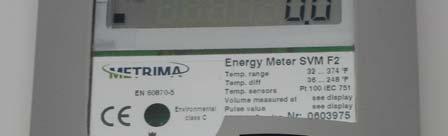
7 3 Handling 3.1 Display Every F2 is equipped with an LCD (Liquid Crystal Display). The data retrieved by the calculator is organized and accessible through display sequences visible on the LCD. The left-most digits indicate the current selected sequence. The right-hand digits show the relevant value for the currently selected sequence. A tap of the display button results in a move to the next value in the your current sequence. To change to a new sequence, press and hold the Display button until the left-hand digits starts to increment. Release the button at the desired sequence. The right-hand digits will now display the values and readings related to your newly selected sequence. If you wish to return the display to the original sequence, simply do not press the display button for ~60 seconds. The display is configured as below: 1. Sequence digits 2. Flow sensor pulse indicator 3. Relevant value shown here, maximum 7 digits 4. Arrow that indicates unit for displayed value m³ C m³/h kw F2 Made in Sweden Nr: OPTO interface Display button HOLD xx xx xx PUSH 70 xx Fig , Tap to toggle to next value. Press and hold to enter next sequence.
8 3.2 Display sequence table 10 Accumulated energy (Default position) 11 Accumulated volume according to flow sensor 1 12 Display test, see fig Accumulated volume for pulse input 1 14 Accumulated volume for pulse input 2 15 Error code, see Error code 16 Error time, [Minutes] 20 Momentary power 21 Momentary flow 22 High temperature, 0 decimals 23 Low temperature, 0 decimals 24 Temperature difference, 1 decimal 30 Account days, when values are stored, [YYMMDD] 31 Account days, Accumulated energy 32 Account days, Accumulated volume according to flow sensor 33 Account days, Accumulated volume according to energy calculation 34 Account days, Accumulated volume pulse input 1, [gal] 35 Account days, Accumulated volume pulse input 2, [gal] 36 Possible error code, at time of storage of account days 37 Possible accumulated error time, at the time of storage account days, [Minutes] 40 Monthly registers, date when values are stored, [YYMMDD] 41 Monthly registers, Accumulated energy 42 Monthly registers, Accumulated volume according to flow sensor 43 Monthly registers, Accumulated volume according to energy calculation 44 Monthly registers, Accumulated volume pulse input 1, [m3] 45 Monthly registers, Accumulated volume pulse input 2, [m3] 46 Possible error code, at time of storage of monthly register 47 Possible accumulated error time, at the time of storage, [Minutes] 4x Following monthly registers (loop back) 50 Operating time, [Hours] 51 Relevant date, [YYMMDD] 52 Relevant time, [HH.MM] 53 Recommended date for battery replacement, [YYMMDD] 60 Communication address, Primary address A0 Communication address, Secondary address (normally same as meter S/N) bx Calculator serial number (S/N) 63 Pulse value [l/p] 64 Placing of flow sensor, [H/L], L = Low, H = High 70 Accumulated volume corresponding to accumulated energy 73 Last remote reading of accumulated energy 74 Time since latest remote reading of accumulated energy, [Hours] 75 Accumulated total error time, [Minutes] 1 The calculator has two values for accumulated volume. Sequence 11 is calculated relative to flow pulses. Value 70 is incremented in conjunction with energy calculation. 8
9 Error codes Error codes are shown in display sequence 15. Code Description 0001 Break in low temperature sensor (L) 0002 Short circuit in low temperature sensor (L) 0004 Break in high temperature sensor (H) 0008 Short circuit in high temperature sensor (H) 0005 Error code combination A Error code combination Low flow 0100 Battery replacement recommended Display sequence 15 - error codes 9
10
11 4 Service Note: Do not attempt to change any values until you have read and understand all sections of this manual. If you have any questions, please contact TCT before attempting to access or alter any values in this mode. After installing the F2, please bypass this mode by skipping through to the exit sequence as shown below in table 4.1 As mentioned in section 1, most calculators will enter the Service Mode upon installation and exit of the Transport Mode. The Service Mode allows for changes to certain parameters of the calculator. If you wish to re-enter the Service Mode, use the following steps: 1. Break the seal to the Service button (fig 3.2) on the rear side of the calculator with a small screwdriver. 2. Press and hold down the Display button on the front of the calculator. 3. While holding the Display button pressed, use the screwdriver to press and hold the Service button. 4. Keep the Service button and Display button pressed for ~5 seconds. 5. First release the Display button, then release the Service button. The calculator is now in the Service mode, and the display will show 00 in the upper left-hand corner as confirmation. To leave the Service mode follows the same procedure described above. Navigating through the Service sequence and changing values This is similar to cycling through the F2 s main LCD sequences as discussed in section 3. Tapping the Display button alters the value for the blinking digit. To change to the next digit, hold the Display button pressed until next digit starts to blink. To change to the Service sequence hold, the Display button pressed until next service sequence is reached (indicated by the left-hand digits). Note: The changed values are not saved until the next sequence is displayed. Service Sequences Time 00 is the real time clock, with the right hand digits representing the format HHMM Date 01 the relevant date in the format YYMMDD Pulse value 02 and 03 indicate pulse values. 02 is the sequence for the pulse value itself and 03 denotes the number of decimals applied for the pulse value. Example 1 The pulse value shall be 2.5 [l/p]. 02 shall be 2500, and 03 shall be 3. E.g with 3 decimals = 2.5 [l/p]. Example 2 The pulse value shall be 10 [l/p]. 02 = 1000, 03 = 2. E.g. 10 [l/p] Account days 04 and 05 are account days with the format MMDD. F2 calculators can store up to two. To deactivate the account days set MMDD to For most applications, this sequence can be skipped.
12 2.2.4 Communication address 06 is the communication address. The address is set with four digits. Skip this sequence unless intending to implement a remote reading device, such as Mcomm Flow sensor placing 08 sets flow sensor placing, format 0 or 1. 0 = Flow sensor installed in low (cold) 1 = Flow sensor installed in high (hot) Reset the accumulated error time 07 is the reset value for accumulated error time. Format 0 or 1. 0 = Reset error time 1 = Do not reset error time Recommended date for battery replacement 09 sets the battery replacement date, format YYMMDD. 2.2.A Exit service mode 0A allows you to exit the service mode depending on which value is set: 0 = Return to sequence 00 1 = Exit Service Sequence 4.1 Service sequence table Service sequence Description 00 Time [hhmm] 01 Date [YYYMMDD] 02 Pulse value for flow meter, without decimal placing, 4 digits 03 Pulse value decimal placing, Account days 1, MMDD 05 Account days 2, MMDD 06 Primary communication address, set with 3 digits, e.g. 5 is set Reset stored error time 0 = Reset stored error time (default) 1 = Do not reset error time 08 Flow sensor placing, 0 = Installed at low end (L / cold) 1 = Installed at high end (H / hot) 09 Recommended battery replacement date. Do not change without consulting with TCT Solar. 0A Exit service sequence, 1 = EXIT 2 = return to service sequence 00 Table 4.1, Service sequence, Servic e Test Save data Fig. 3.2a, Service button Service button 12
13 5 Seals 1. Service seal 2. Test seal 3. Electronic seals 4. Installation seals 1 SV SV SV SV SV
14
15 6 Technical data 6.1 Power supply Battery 3V 2.2Ah Maximum operation time: 10 yrs Table 7.1, Power supply 6.2 Temperature sensors Approved and matching pairs of temperature sensors of the type Pt 100 or Pt 500 are to be used, with a maximum current of 4 A for PT100. Cable area [gauge] Maximum cable length for PT100 sensors [ft] Table 7.2, Cable areas for PT Flow sensors Flow sensor with pulse output. Max. frequency [Hz] 12 Pulse value range [l/p] Min. pulse length [ms] 40 Max. voltage [V] 3 Max. cable length [ft] 49.2 Table 7.2, Technical specifications 6.4 Temperature range Temperature range F Temperature difference 2 120K Table 7.4, Temperature range 6.5 Ambient temperature & temperature class F2 complies with the prerequisites for Environmental Class C according to EN1434. Ambient temperature storage/transport -4 F to 158 F Ambient temperature operation 41 F to 131 F Table 7.5, Ambient temperature ranges

16 6.6 Flow sensor placing F2 can be configured for flow sensor placement in high or low end of the pipe (supply or return pipe). This is marked H = high (hot) or L = low (cold) in display sequence Maximum values for power The values below represent MWh and standard decimal setting Pulse value [l/p] Maximum power [ MW ] Table 7.7, maximum power displays relative to pulse values 6.8 Dynamic behavior Instantaneous measurements are calculated for each flow sensor pulse, when the time between the pulses is five (5) seconds or longer. If the time between pulses is less than five seconds, measurements takes place every pulse and are added for 5 seconds. When the period between the flow sensor pulses exceeds 60 seconds, a measurement takes place every 60th second. For this kind of measurement, only the temperature is updated. 6.9 Data output interface M-Bus acc. to EN Via OPTO-interface (EN ) bus connection (terminals) Table 7.9, data output interfaces 16
17 6.10 Pulse outputs F2 can be equipped with two pulse outputs for Energy (pulse output 1) and Volumetric values (pulse output 2). The last digit and unit of energy will determine pulse weight. Example: sequence 10 (energy) on display is shown MWh => pulse weight = 0.01 MWh/pulse. Pulse output 1 Energy - one pulse per display update in the energy register (sequence 10 ). Pulse output 2 Volume - one pulse per display update in the flow register (sequence 11 ). Pulse value [ms] 250 Voltage [V] 3 30 Maximum current [µa] 20 Table 7.10, Pulse output data 6.11 Pulse inputs Standard F2s are equipped with two pulse inputs. The pulse inputs can be used for measuring another meter equipped with pulse outputs. The pulse inputs can be set as volume registers. These registers accumulate the pulses into two volume registers with the value [gal]. Frequency [Hz] 12 Min. pulse duration [ms] 40 Max. Voltage [V] 3 Table 7.11, Pulse inputs +3V 6.12 Alarm output The F2 is equipped with one alarm output. The alarm output sends a pulse every hour as long as an error code exists. The pulse duration 250 [ms] can be altered using the Service program version 2 or higher in 125 [ms] increments. Alarm frequency when an Once every hour error exists Pulse [ms]
18 7 Appendix Displayed values on the F2 calculator will vary depending on the set pulse value, and follow the diagram below. Smaller pulse values result in readings to more decimal places than larger pulse values. 7.1 Decimal placing F2 The decimal setting for F2 follows utility standards. Pulse value [l/p] MWh GJ m³ KWh MBTU kw m³/h Table A Decimal placing Pulse value [l/p] m³
19 7.2 Ordering Key F2 ABCDEFGHIJ KLM A 1 Pt100 2-wire measurement, flow in low temperature A 2 Pt100 2-wire measurement, flow in high temperature A 5 Pt500 2-wire measurement, flow in low temperature A 6 Pt500 2-wire measurement, flow in high temperature B 1 Battery supply B 2 Bus supply B 5 24 VAC C 0 Kt Input 2.5 l/p C 1 Kt Input 25 l/p C 2 Kt Input 250 l/p C 3 Kt Input 2500 l/p C 4 Kt Input 1 l/p C 5 Kt Input 10 l/p C 6 Kt Input 100 l/p C 7 Kt Input 1000 l/p C 8 KWh D A MWh C B GJ C C MBTU D 0 Standard order D 1 Special, Extra information at the order, e.g. customer information D 2 Pulse Inputs, 2.5 l/p, dec. 2 D 3 Pulse Inputs, 25 l/p, dec. 1 E - Pulse Inputs, 250 l/p, dec. 0 E S Pulse Inputs, 1 l/p, dec. 3 F 1 Pulse Inputs, 10 l/p, dec. 2 F 2 Pulse Inputs, 100 l/p, dec. 1 F 3 Pulse Inputs, 1000 l/p, dec. 0 F 5 Pulse Outputs F 6 Backlight on display (not recommended on battery supplied meters) F 7 No Backlight F 8 For wall mounting, with adapter incl. F 9 Compact mounted with Hydrometer BR431 G 0 Compact mounted with other flow sensor, with adapter incl. G 1 With adapter for BR471 G 4 With out adapter G 5 Standard H 0 Standard H 1 Country code, 3 = Standard English H 2 Standard H 3 Standard H 4 Pt100 2-wire measurement, flow in low temperature I - Pt100 2-wire measurement, flow in high temperature J 1 Pt500 2-wire measurement, flow in low temperature K 1 Pt500 2-wire measurement, flow in high temperature L 0 Battery supply M 0 Bus supply 19
20
21 101 Copeland Street Jacksonville, Florida Phone: Fax:
SVM F2 Calculator. A small competent calculator for compact or wall montage. Users manual
 SVM F2 Calculator A small competent calculator for compact or wall montage Users manual Users manual F2 1 INSTALLATION... 5 1.1 AT DELIVERY... 5 1.2 CONNECTIONS... 6 2 MOUNTING... 7 2.1 MOUNTING ON A
SVM F22. Calculator for heating or cooling applications. Data sheet
 SVM F22 Calculator for heating or cooling applications Data sheet Application area F22 is a flexible calculator designed for measuring and monitoring of small to medium-sized heating or cooling installations.
SVM F27 Compact. Ultrasonic heatmeter. Data sheet
 SVM F27 Compact Ultrasonic heatmeter Data sheet Application field F27 is a heat meter for debiting and monitoring heat energy consumption. F27 is a flexible compact heat meter with an ultra sonic flow
SVM F27 Compact. Compact heat meter. Users manual
 SVM F27 Compact Compact heat meter Users manual Users manual 1 INSTALLATION... 5 1.1 CONNECTION AND MOUNTING... 5 1.1.1 Flow part, mounting... 5 1.1.2 Temperature sensors, mounting... 5 1.1.3 Calculator,
SVM F27 / C27. Ultrasonic BTU meter for heating or cooling. Data sheet
 SVM F27 / C27 Ultrasonic BTU meter for heating or cooling Data sheet Application field F27/C27 is a BTU meter for debiting and monitoring energy consumption (F27 for heating and C27 for cooling). F27/C27
SVM F22 SVM F27. Calculator for heating or cooling applications. Ultraljudsmätare. Installation Guide. Datablad
 F Calculator for heating or cooling applications Ultraljudsmätare F7 Installation Guide Datablad Calculator F installation guide For more detailed information, see F manual Delivery The calculator is normally
Brunata Optuna H. Properties. Counter
 Brunata Optuna H Brunata Optuna H measures energy consumption in large and small heating and cooling systems as well as combined heating and cooling systems. The meter is compact and belongs to the first
SONOMETER TM 1100 Ultrasonic compact energy meter
 Data sheet SONOMETER TM 1100 Ultrasonic compact energy meter Description/Application MID examination certificate no. : DE-10-MI004-PTB003 The SONOMETER 1100 is an ultrasonic static compact energy meter
SHARKY 775 ULTRASONIC COMPACT METER. 4 Approved according EN 1434 and MID in class 2 with dynamic range of 1:250 (qi:qp) in class 2
 in class 2") APPLICATION ultrasonic compact energy meter can be used for measuring the energy consumption in heating / cooling application for billing purposes. The measurement principle is static and based on the
APPLICATION ultrasonic compact energy meter can be used for measuring the energy consumption in heating / cooling application for billing purposes. The measurement principle is static and based on the
Brunata Optuna H Ultrasonic energy meter Type 775 Installation Guide Edition 1.2
 Ultrasonic energy meter Type 775 Installation Guide Edition 1.2 UK-QB101575 / 29.05.2012 Brunata a/s is a Danish owned company. We have more than 90 years of experience within developing and producing
SonoMeter 31 Energy Meters
 SonoMeter 31 Energy Meters Description MID examination certificate no.: LT-1621-MI004-023 The Danfoss SonoMeter 31 is a range of ultrasonic, compact energy meters intended for measuring energy consumption
SONOMETER TM 1100 Ultrasonic compact energy meter
 Data sheet SONOMETER TM 1100 Ultrasonic compact energy meter Description/Application MID examination certificate no. : DE-10-MI004-PTB003 The SONOMETER 1100 is an ultrasonic static compact energy meter
INFOCAL 8 Energy calculator
 Data sheet INFOCAL 8 Energy calculator Description/Application MID examination certificate no.: DE-10-MI004-PTB008 The INFOCAL 8 is an energy calculator e.g. for combination with SONO 1500 CT especially
SHARKY 775 ULTRASONIC COMPACT METER. 4 Approved according EN 1434 and MID in class 2 with dynamic range of 1:250 (qi:qp) in class 2
 in class 2") APPLICATION ultrasonic compact energy meter can be used for measuring the energy consumption in heating / cooling application for billing purposes. The measurement principle is static and based on the
APPLICATION ultrasonic compact energy meter can be used for measuring the energy consumption in heating / cooling application for billing purposes. The measurement principle is static and based on the
SHARKY 775 ULTRASONIC COMPACT METER. 4 Approval with dynamic range up to 1:250 (qi:qp) MID in class 2 (depends on meter size), standard 1:100
 MID in class 2 (depends on meter size), standard 1:100") APPLICATION ultrasonic compact energy meter can be used for measuring the energy consumption in heating / cooling application for billing purposes. The measurement principle is static and based on the
APPLICATION ultrasonic compact energy meter can be used for measuring the energy consumption in heating / cooling application for billing purposes. The measurement principle is static and based on the
Supercal 531 Multi function Integrator that lives up to Your highest expectations
 n Thermal Energy n Flow Metering n Supercal 531 Multi function Integrator that lives up to Your highest expectations Supercal 531 Multi functional integrator with unlimited options The Supercal 531 convinces
Infocal 9 Energy calculator
 Infocal 9 Energy calculator Description/Application MID examination certificate no.: LT-1621-MI004-028 The INFOCAL 9 is an energy calculator, e.g. for combination with or SonoSensor 30. It is especially
3 PHASE ENERGY ELECTRONIC METERS MKT & MKT2. (Code to ) INSTRUCTION MANUAL ( M / 00 A ) (c) CIRCUTOR S.A.
 INSTRUCTION MANUAL ( M / 00 A ) (c) CIRCUTOR S.A.") 3 PHASE ENERGY ELECTRONIC METERS MKT & MKT2 (Code 7 71 071 to 7 71 083) INSTRUCTION MANUAL ( M 981 200 / 00 A ) (c) CIRCUTOR S.A. ----- MKT- MKT2 - ELECTRONIC METERS -------- M-981 200 --- Page Nº 2 3
3 PHASE ENERGY ELECTRONIC METERS MKT & MKT2 (Code 7 71 071 to 7 71 083) INSTRUCTION MANUAL ( M 981 200 / 00 A ) (c) CIRCUTOR S.A. ----- MKT- MKT2 - ELECTRONIC METERS -------- M-981 200 --- Page Nº 2 3
1.2 M-Bus (optional) The M-Bus is a galvanically isolated interface for the transmission of meter data (absolute values).
 The M-Bus is a galvanically isolated interface for the transmission of meter data (absolute values).") Operating Instructions Communication Interfaces 1 Interfaces and Options 1.1 Optical (infrared) interface For communication with the optical interface an optocoupler and the Device Monitor software are
Operating Instructions Communication Interfaces 1 Interfaces and Options 1.1 Optical (infrared) interface For communication with the optical interface an optocoupler and the Device Monitor software are
6000 W, 2450 MHz Microwave Generator GMP 60K SM 56T400 FST 3 IR
 6000 W, 2450 MHz Microwave Generator GMP 60K SM 56T400 FST 3 IR Power supply It is based upon the latest switch mode power supply technology, offering size reduction (smallest 6 kw available on the market,
SUPPLY NETWORK ANALYZER. CVMk SERIES. CVMk-4C SERIES INSTRUCTION MANUAL. ( M / 00 B - Manual 1 / 2 ) (c) CIRCUTOR S.A.
 (c) CIRCUTOR S.A.") SUPPLY NETWORK ANALYZER CVMk SERIES & CVMk-4C SERIES INSTRUCTION MANUAL ( M 981 171 / 00 B - Manual 1 / 2 ) (c) CIRCUTOR S.A. ----- Supply network analyzer CVMk and CVMk-ITF ------ Manual 1 / 2 --- Page
SUPPLY NETWORK ANALYZER CVMk SERIES & CVMk-4C SERIES INSTRUCTION MANUAL ( M 981 171 / 00 B - Manual 1 / 2 ) (c) CIRCUTOR S.A. ----- Supply network analyzer CVMk and CVMk-ITF ------ Manual 1 / 2 --- Page
ENCORE 300 SERIES INSTALLATION AND OPERATING INSTRUCTIONS
 ENCORE 300 SERIES INSTALLATION AND OPERATING INSTRUCTIONS Copyright 2002-2006 PRI Ltd. 9600-3004-2 Issue C Information contained within this document is subject to change without notice and does not represent
Eltek TU GenII GD900A Energy monitor (multidrop NDRail350) transmitter user instructions
 transmitter user instructions") Eltek TU1043 - GenII GD900A Energy monitor (multidrop NDRail350) transmitter user instructions System configuration diagram GD900A NDRail350 AC supply 240V nominal RS485 AC AC AC For 1 x three phase load
Eltek TU1043 - GenII GD900A Energy monitor (multidrop NDRail350) transmitter user instructions System configuration diagram GD900A NDRail350 AC supply 240V nominal RS485 AC AC AC For 1 x three phase load
RAY MECHANICAL COMPACT METER. 4 MID approved class 2 from ND 15 mm qp 0,6 m3/h up to ND 40 mm qp 10 m3/h
 APPLICATION Ray is a fully electronic multi-jets compact heat meter or compact cooling and heat meter with impeller scanning for recording energy and volume data. Ray is equipped with 2 temperature sensors.
ULTRASONIC D. Compact ultrasonic heat meter
 ULTRASONIC D Compact ultrasonic heat meter Applications ULTRASONIC D is a compact ultrasonic heat meter used for measuring energy in heating and cooling plants in facility management systems as well as
ENA33LCD. Power line analyzer. User and service manual. Obrezija 5 SI-1411 Izlake
 ENA33LCD Power line analyzer User and service manual version 2.9 (FW version 6.8 and newer) ETI, d.o.o. Obrezija 5 SI-1411 Izlake www.etigroup.eu/products-services 1. Front control panel and terminal plate
RAY COMPACT ENERGY METER MECHANICAL
 APPLICATION Fully electronic compact heat meter or compact cooling and heat meter with impeller scanning for recording energy and volume data. Highly accurate recording of all billing data in a heating
12/2 Product overview. 12/3 7KT1 14, 7KT1 53 E-counters. 12/9 7KT1 11, 7KT1 12 digital measuring devices. 12/11 7KT1 0 analog measuring devices
 BETA Measuring /2 Product overview /3 7KT1 14, 7KT1 53 E-counters /9 7KT1 11, 7KT1 digital measuring devices /11 7KT1 0 analog measuring devices / 7KT5 8 time and pulse counters /14 7KT5 5, 7KT5 6 time
USER MANUAL ENGLISH 1450 COIN COUNTER & SORTER
 USER MANUAL ENGLISH 1450 COIN COUNTER & SORTER INTRODUCTION ENGLISH Thank you for purchasing the Safescan 1450 coin counter and sorter. For proper use and maintenance, we advise to read this user manual
SONOMETER TM 1000 Ultrasonic compact heat meter
 SONOMETER TM 1000 Ultrasonic compact heat meter Description/Application The SONOMETER 1000 is a static compact heat meter with fully electronic measurement based on the ultrasonic principle. It is especially
R PROFLAME Instruction Book Collection
 9.956.028 R00 584 PROFLAME Instruction Book Collection 4-17 18-29 584 PROFLAME System 30-39 Appendix: DIP SWITCH NUMBER (0=ON 1=OFF) 40-41 4-17 Fig. 1 The SIT is a device that allows, in conjunction with
Electronic Heating Energy Meters
 5 333 SIEMECA Electronic Heating Energy Meters WFM... WFQ... Electronic, mains-independent meters to acquire heating energy consumption in autonomous heating and domestic hot water plants. Storage and
INSTALLATION & OPERATION MANUAL
 INSTALLATION & OPERATION MANUAL AN25 Totalizer/ Rate Indicator DOC#: MN-AN25.doc Sponsler Co., Inc. AN25 Totalizer/Rate Indicator pg. 2 DOC#: MN-AN25 SPECIFICATIONS Temperature: Operating 0 to 70 C Storage
MULTICAL Energy meter TS PTB. Application
 MULTICAL Energy meter Can be connected to flow meters from qp 0.6 to 3000 m 3 /h Additional connection for electricity or water meters Measures heat or cooling Leak detection Battery back-up Data logging
SonoSelect 10 and SonoSafe 10 Energy Meters
 SonoSelect 10 and SonoSafe 10 Energy Meters Description The Danfoss SonoSelect 10 and SonoSafe 10 are ultrasonic compact energy meters intended for measuring energy consumption in heating and cooling applications
Installation & User Manual Radio Remote RCS-10E
 Installation & User Manual Radio Remote RCS-10E SLEIPNER MOTOR AS P.O. Box 519 N-1612 Fredrikstad Norway Tel: +47 69 30 00 60 Fax: +47 69 30 00 70 www.side-power.com sidepower@sleipner.no Made in Norway
SULTANATE OF OMAN METERING AND DATA EXCHANGE CODE
 1.0 GENERAL SULTANATE OF OMAN METERING AND DATA EXCHANGE CODE STANDARD: OES-22F THREE PHASE KILOWATT-HOUR DIGITAL METERS, CURRENT TRANSFORMER OPERATED, CONNECTED FOR SERVICE CONNECTIONS Electronic three
RAY MC COMPACT ENERGY METER MECHANICAL
 APPLICATION Fully electronic measuring capsule heat meter, heat and cooling meter or cooling meter with impeller scanning for volume measuring and energy calculation. Highly accurate recording of all billing
PREMIER INSTALLATION AND OPERATING INSTRUCTIONS
 PREMIER INSTALLATION AND OPERATING INSTRUCTIONS Copyright 2002-2006, PRI Ltd. 9600-3003-2 Issue C Information contained within this document is subject to change without notice and does not represent a
PLA 33. Power line analyzer. User and service manual. version 2.4
 PLA 33 Power line analyzer User and service manual version 2.4 Content. Front control panel and terminal plate...3 7.2.2. System frequency setting...0 2. Device description...4 7.2.3. Password protection...0
Micromate User Manual
 Microcoin Table of Contents Page Essential Information 2 1.0 Connection and Configuration 3 1.1 Connection 3 1.2 Switch On 4 1.3 Configuration for Use 4 2.0 Check the Configuration of a Validator 5 2.1
Heat meter Q heat 5 US
 Heat meter Q heat 5 US Ultrasonic heat meter with ultrasonic measurement technology (runtime difference method) with IrDA interface and an interface for retrofitting external modules. Exact measurement
Dial-type digital bar graph. LEDs for Open Collector, Relays and Warning Indicator
 Specifications General Input Channels One Input Types Digital (S 3 L) Serial ASCII, TTL level, 9600 bps Frequency Range 0.5 to 1500 Hz Accuracy 0.5% of reading Measurement Types Flow, ph/orp, Conductivity/Resis
Signet 9900 Transmitter
 Signet 9900 Transmitter Member of the SmartPro Family of Instruments Features Panel Mount Field Mount Multi-Parameter input selection Large auto-sensing backlit display with at a glance visibility Dial-type
impact VC-500LR Monolight INSTRUCTIONS
 impact lighting equipment and accessories VC-500LR Monolight INSTRUCTIONS Congratulations on your purchase of the Impact VC-500LR Monolight. We feel that it will contribute much to your photographic skill
MULTICAL 601 DATA SHEET
 Precise measuring of heat and cooling up to 3000 m³/h Pt100, 2-wire Pt500, 2- and 4-wire Available with ULTRAFLOW from q p 0.6 to 1000 m³/h 24 VAC, 230 VAC or 10 years battery supply Data logging for 460
Installation & Operation Manual
 Badger Series 340N2 METASYS Compatible Energy Transmitter Installation & Operation Manual BadgerMeter, Inc. 872033 Rev. 6 4-09 Introduction The Badger Meter Series 340N2 Btu transmitter is an economical,
FLOMID-MX Control unit for electromagnetic flowmeters USERS MANUAL. instrumentación para fluidos. Realitzat: Revisat R+D Electrònic: Aprovat: Data:
 instrumentación para fluidos FLOMID-MX Control unit for electromagnetic flowmeters USERS MANUAL Realitzat: Data: Revisat R+D Electrònic: Data: Revisat Of. Comercial: Data: Aprovat: Data: R-MI-Flomid-MX
A1000 ALPHA and A1200 ALPHA Meter Installation Instructions. General. Installation. For A1000 ALPHA Type R, A1000 ALPHA Type C, and A1200 ALPHA Meters
 January 003 IL4-401B A1000 ALPHA and A100 ALPHA Meter Installation Instructions For A1000 ALPHA Type R, A1000 ALPHA Type C, and A100 ALPHA Meters General This leaflet contains general installation instructions
M1 Series. Humidity - Temperature Transmitter INSTRUCTION MANUAL
 M1 Series Humidity - Temperature Transmitter INSTRUCTION MANUAL 20031110 -2- CONTENTS Overview... 3 Operation... 4 Power supply... 4 Operating range and limits... 4 Temperature compensation of the humidity
Aqua-Gen 3BR INSTRUCTIONS
 Aqua-Gen 3BR INSTRUCTIONS INSTALLATION INSTRUCTIONS CONTROLLER: Find a suitable location to mount the control box* radio note. The controller must be installed out of direct weather and no closer than
Instruction. INFOCAL 8 Energy calculator. 1.0 Table of contents. 2.0 Safety notes and product information
 Instruction INFOCAL 8 Energy calculator 1.0 Table of contents 1.0 Table of contents...1 2.0 Safety notes and product information...1 3.0 Installation of energy calculator...2 4.0 Installation of temperature
MultiCube Multi-Function Electricity Meter. Installation and Operation
 MultiCube Multi-Function Electricity Meter Installation and Operation PREFACE MultiCube Operating Guide Revision 1.08 Jan 2007 This manual represents your meter as manufactured at the time of publication.
ME162 Single-Phase Electronic Meter
 Energy Measurement and Management ME162 Single-Phase Electronic Meter Technical Description Version 1.1, 02.06. 2006 Index: ME162 Electronic single-phase time-of-use kwh-meter... 3 1. Meter appearance...
Siemens Switzerland Ltd HVAC Products. SIEMECA Electronic Heat and Cooling Meters
 5 338 SIEMECA Electronic Heat and Cooling Meters WFR WFN Electronic, mains-independent meters to acquire the heat and cooling energy consumption in autonomous heating, cooling and domestic hot water plants.
Instruction. SONOMETER 1100 Ultrasonic compact energy meter. 1.0 Table of contents. 2.0 Safety notes and product information
 Instruction SONOMETER 1100 Ultrasonic compact energy meter 1.0 Table of contents 1.0 Table of contents...1 2.0 Safety notes and product information...1 3.0 Installation of energy meter...2 4.0 Installation
Contents. Introduction and description Package contents Device identification PM Options... 80
 Contents 1 Introduction and description Package contents... 77 Device identification... 77 2 Characteristics PM500... 78 Options... 80 3 Installation Front-panel cut-out... 82 Mounting... 82 4 Connections
Power-meters three-phase
 ADP3-0C Digital display symbols for all three phases: I - U-PF -Hz -P- Q-S, active energy export/import by IR side set up communication Power-meters three-phase Direct connection 0 A Application The new
Signet 9900 Transmitter
 Signet 9900 Transmitter Member of the SmartPro Family of Instruments Features Panel Mount Field Mount Multi-Parameter input selection Large auto-sensing backlit display with at a glance visibility Dial-type
WIRELESS Energy Monitor - Smart Meter
 Energy saving made simple MONITOR CONTROL SAVE WIRELESS Energy Monitor - Smart Meter Monitors your electricity use and cost in real time Instruction Manual EW4500 IMPORTANT Please retain your Instruction
MULTICAL 602 DATA SHEET
 Complete range of communication modules High Power RadioRouter module Data loggers Info loggers Data backup in case of power failure EN 1434 MID-2004/22/EC M11 0200 Heat and cooling meters with unlimited
INTRODUCING SOME GREAT NEW PRODUCTS FROM OUR DWYER INSTRUMENTS RANGE:
 Unit 1 / 14 Biscayne Way Jandakot WA 6104 P.O. Box 3232, Success WA 6964 Tel: (08) 9414 7666 Fax: (08) 9414 7677 Email: dg@dginstruments.com.au Website: www.dginstruments.com.au A.B.N: 59 113 005 959 DATE:
TROVIS 5500 Automation System TROVIS 5578 Heating and District Heating Controller. Mounting and Operating Instructions EB 5578 EN
 TROVIS 5500 Automation System TROVIS 5578 Heating and District Heating Controller Mounting and Operating Instructions EB 5578 EN Firmware version 2.2x Edition May 2015 Definition of signal words DANGER!
SONOMETER 2000 Ultrasonic heat meter
 SONOMETER 2000 Ultrasonic heat meter Description/Application The SONOMETER 2000 is an ultrasonic heat meter especially designed for measuring the water and energy consumption in district heating networks.
3-phase meter with direct connection and pulse or Modbus RS485 output
 87045 LIMOGES Cedex Telephone: +33 (0)5 55 06 87 87 Fax: +33 (0)5 55 06 88 88 3-phase meter with direct connection and CONTENTS PAGES 1. Description, usage... 1 2. Range... 1 3. Dimensions... 1 4. Positioning...
Operating manual IMPORTANT! READ CAREFULLY BEFORE USE. KEEP FOR THE ENTIRE LIFE OF THE PRODUCT. Heat meters. Deltamess TKS-WM compact heat meter
 Operating manual IMPORTANT! READ CAREFULLY BEFORE USE. KEEP FOR THE ENTIRE LIFE OF THE PRODUCT. Heat meters Deltamess TKS-WM compact heat meter 1 Contents Safety and warranty... 3 Radio system... 3 Lithium
SolarEdge Export Limitation Application Note
 SolarEdge Export Limitation Application Note Europe and APAC Version 2.3 Disclaimers Disclaimers Important Notice Copyright SolarEdge Inc. All rights reserved. No part of this document may be reproduced,
MA7200 PLUS INVERTER SERIES PID Quick Start Manual For Fan and Pump Applications
 MA7200 PLUS INVERTER SERIES PID Quick Start Manual For Fan and Pump Applications 3 to 75 HP Models- MA7200-2003-N1 Thru MA7200-2040-N1 (230V) & MA7200-4003-N1 Thru MA7200-4075-N1 (460V) speed time Rev.
I n s t a l l a t i o n M a n u a l. T E D P r o L i t e A B C. f o r. Shop for The Energy Detective products online at: Rev 3.
 Rev 3.5 I n s t a l l a t i o n M a n u a l f o r T E D P r o H o m e T E D P r o L i t e A B C Shop for The Energy Detective products online at: 1.877.766.5412 IMPORTANT: The installation of your TED
Temperature Controller model MFC-301/T-Dry. Version for Dry Transformers and Motors. Technical Manual. Licht
 Temperature Controller model MFC-301/T-Dry Version for Dry Transformers and Motors Technical Manual Licht Contents 1 Introduction 2 2 Operating principle 3 2.1 General principle 3 2.2 RTD operation 3 3
RI-F200 Series. Single and Three Phase Multifunction Energy Meter. Telephone : +44 (0) Displayed Parameters
 Displayed Parameters") RI-F200 Series Single and Three Phase Multifunction Energy Meter DIN 96 panel mounted -/1A or -/5A current transformer input Single phase or three phase network compatible Programmable voltage and current
RI-F200 Series Single and Three Phase Multifunction Energy Meter DIN 96 panel mounted -/1A or -/5A current transformer input Single phase or three phase network compatible Programmable voltage and current
Technical Information
 Date of last update: Aug-14 Ref: REFRIGERATION - CONTROLLING DIGITAL SCROLL Application Engineering Europe 1 Introduction Refrigeration applications such as retail and convenience stores are requesting
1: Introduction : Caution : Tips for Reading this Manual : Preface : System Highlights : Receiver
 1: Introduction....1 1 2: Caution.... 2 2 3: Tips for Reading this Manual....3 3 4: Preface....4 4 5: System Highlights....6 6 6: Receiver..7 7 6.1: Specifications......7 7 6.2: Receiver Operation... 7
RI-D440. Three Phase easywire Multifunction DIN Rail Energy Meter. Telephone : +44 (0) Displayed Parameters
 Displayed Parameters") RI-D440 Three Phase easywire Multifunction DIN Rail Energy Meter Four module DIN rail mounted Energy pulse LED 330mV Input from easywire CTs (or -/1A and -/5A current transformer input with TAS-SCTEWA
RI-D440 Three Phase easywire Multifunction DIN Rail Energy Meter Four module DIN rail mounted Energy pulse LED 330mV Input from easywire CTs (or -/1A and -/5A current transformer input with TAS-SCTEWA
Signet 9900 Transmitter
 Signet 9900 Transmitter Member of the SmartPro Family of Instruments Features Multiple sensor types supported with one instrument Dial-type digital bar graph Modules are field installable and replaceable
Operating Guide October 2006
 Operating Guide October 2006 Safety 1 Safety This manual represents your meter as manufactured at the time of publication. It assumes standard software. Special versions of software may be fitted, in which
Keyed latch. Cover. Service Outlet 115VAC, 15A. Plastic base. Unpack. Operator. the Operator
 Service Outlet Quick Start Steps Keyed latch Cover 115VAC, 15A Plastic base Operator Unpack the Operator Site Planning and Operator Installation The illustrations and instructions presented in this guide
Dual T/C & RTD Calibrator With Auto Stepping
 Model 525 Dual T/C & RTD Calibrator With Auto Stepping Practical Instrument Electronics Operating Instructions Basic Keypad Operations j EZ-Check Switch For Simulation - Slide the switch to select from
Laboratory Grade Instruments Series & 4021 Power Meter SERIES Power Sensor
 Laboratory Grade Instruments 4020 Series & 4021 Power Meter Semiconductor 4020 SERIES Power Sensor 4021 4022 4024 4025 Power Input 300 mw to 1 kw 300 mw to 1 kw 3 W to 10 kw 3 W to 10 kw (1.2 kw max.)
Signet 9900 Transmitter
 Signet 9900 Transmitter Member of the SmartPro Family of Instruments Features Field Mount Multi-Parameter input selection Large auto-sensing backlit display with at a glance visibility Dial-type digital
INSTALLATION & PROGRAMMING MANUAL PROGRAMMABLE TIMER (MODEL LP-2)
") INSTALLATION & PROGRAMMING MANUAL PROGRAMMABLE TIMER (MODEL LP-2) Copyright Lencore Acoustics Corp. All rights reserved. April 2000 CONTENTS Introduction 3 Display 3 Keyboard 4 Installation 4 Set Up 4
INSTALLATION & PROGRAMMING MANUAL PROGRAMMABLE TIMER (MODEL LP-2) Copyright Lencore Acoustics Corp. All rights reserved. April 2000 CONTENTS Introduction 3 Display 3 Keyboard 4 Installation 4 Set Up 4
RAY MC COMPACT ENERGY METER MECHANICAL
 APPLICATION Fully electronic measuring capsule heat meter, heat and cooling meter or cooling meter with impeller scanning for volume measuring and energy calculation. Highly accurate recording of all billing
GIMA Multi-Function Electricity Meter OPERATOR S MANUAL
 GIMA Multi-Function Electricity Meter OPERATOR S MANUAL SIMPSON ELECTRIC COMPANY 520 Simpson Avenue Lac du Flambeau, WI 54538 715-588-3311 FAX: 715-588-7930 Printed in U.S.A. Part No. 06-117285, Edition
Single phase meter with direct connection and pulse or Modbus RS485 output
 87045 LIMOGES Cedex Telephone: +33(0)5 55 06 87 87 Fax: +33(0)5 55 06 88 88 Single phase meter with direct connection CONTENTS PAGES 1. Description, usage... 1 2. Range... 1 3. Dimensions... 1 4. Positioning...
ultego III smart plus
 Ultrasonic heating and cooling meter ultego III smart plus Residential ultego III smart plus Technical description 32 22 101 001 a Date: 07.04.2017 ista Middle East FZE Outstanding features 2/26 Outstanding
TROVIS 5500 Automation System TROVIS 5578 Heating and District Heating Controller. Mounting and Operating Instructions EB 5578 EN
 TROVIS 5500 Automation System TROVIS 5578 Heating and District Heating Controller Mounting and Operating Instructions EB 5578 EN Firmware version 2.30 Edition November 2017 Definition of signal words DANGER!
Installation & User Manual Radio Remote RCS 20E
 Installation & User Manual Radio Remote RCS 20E SLEIPNER MOTOR AS P.O. Box 519 N-1612 Fredrikstad Norway Tel: +47 69 30 00 60 Fax: +47 69 30 00 70 www.side-power.com sidepower@sleipner.no Made in Norway
Aqua-Gen 3PV INSTRUCTIONS
 Aqua-Gen 3PV INSTRUCTIONS INSTALLATION INSTRUCTIONS CONTROLLER: Find a suitable location to mount the control box* radio note. The controller must be installed out of direct weather and no closer than
HEAT CALCULATOR MODEL 212
 HEAT CALCULATOR MODEL 212 July 1998 CONTENTS 1. Overview 3 1.1 Model Number Designation 5 1.2 Conversion Factors 6 2. Specification 7 3. Operation 11 3.1 Display Operation 13 3.1.1 Normal Operation 13
DIGEM f 96 x 48 EK. Applications. Description
 3-349-002-03 1/7.98 Front panel dimensions: 96 x 48 mm LED display: red or green, 14 mm high Max. display range: 19 999 to + 32 765 Modular connectors for flexible use Simple adjustments at front panel
Energate Foundation Meter Data Collector Installation Guide
 Energate Foundation Meter Data Collector Installation Guide The Meter Data Collector works with Foundation s built-in Meter Data Receiver. The collector attaches to the meter provided by your electricity
HDU-SF (Horizontal Distribution Units - Single Flat)
") MAKING MODERN LIVING POSSIBLE Service Guide www.heating.danfoss.com Danfoss A/S is not liable or bound by warranty if these instructions are not adhered to during installation or service. The English language
MAKING MODERN LIVING POSSIBLE Service Guide www.heating.danfoss.com Danfoss A/S is not liable or bound by warranty if these instructions are not adhered to during installation or service. The English language
Centrale de mesure Power Meter PM500 Merlin Gerin
 Notice d'installation et d'utilisation Installation and user manual Centrale de mesure Power Meter PM500 Merlin Gerin 059473_D Introduction and description Package contents c one PM500 power meter with
MULTICAL 602. Data sheet. Heat and cooling meters with unlimited communication
 Data sheet MULTICAL 602 Heat and cooling meters with unlimited communication Complete range of communication modules High Power RadioRouter module Data loggers Info loggers Data backup in case of power
ND 510 ND 550 Y Z SPEC FCT MOD
 HEIDENHAIN Working with the digital readouts ND 510 ND 550 Actual value and input display (7-segment LED, 8 decades and sign) Downwards: X-axis, Y-axis, ND 550 only: Z-axis Select coordinate axis (Z-axis
FIELD MOUNTED RATE TOTALISER MODEL 202D
 FIELD MOUNTED RATE TOTALISER MODEL 202D 1 February 1999 CONTENTS 1. Introduction 1 1.1 Model Number Designation 3 1.2 Intrinsic Safety Considerations 4 2. Specification 6 3. Operation 8 3.1 Display 8
Instruction Manual. The AquaSun 3RP is a premium automatic solar controller with temperature adjustment, manual, winter mode features.
 Instruction Manual DESCRIPTION The AquaSun 3RP is a premium automatic solar controller with temperature adjustment, manual, winter mode features. Aquasun 3 RP Instruction rb2.docx 1 INSTALLATION INSTRUCTIONS
INSTALLATION MANUAL FOR RADIO CONTROL SESAM 6099 TRANSMITTER
 1 (12) MANUAL FOR RADIO CONTROL SESAM 6099 TRANSMITTER 2 (12) Revision History Document ID Version Date Reason A0 2008-01-14 First edition Minor reformatting 3 (12) Table of Contents Revision History...2
Measurement. SITRANS F US Inline. 3/262 Siemens FI Transmitter SITRANS FUS080/FUE080
 Overview The transmitter is available in an IP67/NEMA 4X/6 enclosure and is designed for use in the flowmeters series: SONOKIT (1-path or -path) FUS80 (-path) FUE80 (-path) The transmitter FUS080 is always
Energy Management Energy Meter Type EM21 72R Retro-Fit
 Energy Management Energy Meter Type EM21 72R Retro-Fit Including 3 miniature split-core current sensors 10mm (90A), 16mm (150A) and 24mm (250A) diameter holes Class A (kwh) according to EN50470-3 Class