TOSHIBA CCD Linear Image Sensor CCD (Charge Coupled Device) TCD1209DG
|
|
|
- Sara Stevens
- 5 years ago
- Views:
Transcription
1 TOSHIBA CCD Linear Image Sensor CCD (Charge Coupled Device) TCD1209DG
2 TOSHIBA CCD LINEAR IMAGE SENSOR CCD(Charge Coupled Device) TCD1209DG TCD1209DG The TCD1209DG is a high sensitive and low dark current 2048 elements linear image sensor. The sensor is designed for facsimile, image scanner and OCR. The device contains a row of 2048 elements photodiodes which provide 8lines / mm (200 DPI) resolution across a B4 size paper. The device is operated by 5V pulses and 12V power supply. FEATURES Pixel Number : 2048 Pixel Size : 14μm 14μm (14μm pitch) Photo Sensing element : High Sensitive & Low Dark Current pn Photodiode Clock : 2 phase (5V) Package : 22 Pin CERDIP WDIP22-G H ABSOLUTE MAXIMUM RATINGS (Note 1) CHARACTERISTIC SYMBOL RATING UNIT Clock Pulse Voltage Shift Pulse Voltage RS Pulse Voltage Clamp Pulse Voltage V V SH V RS V CP 0.3 to +8.0 V Power Supply Voltage V OD -0.3 to V Operating Temperature T opr 25 to +60 C Storage Temperature T stg 40 to +100 C PIN CONNECTION (TOP VIEW) Note 1: All voltage are with respect to SS terminals. (Ground) None of the ABSOLUTE MAXIMUM RATINGS must be exceeded, even instantaneously. If any one of the ABSOLUTE MAXIMUM RATINGS is exceeded, the electrical characteristics, reliability and life time of the device cannot be guaranteed. If the ABSOLUTE MAXIMUM RATINGS are exceeded, the device can be permanently damaged or degraded. Create a system design in such a manner that any of the ABSOLUTE MAXIMUM RATINGS will not be exceeded under any circumstances. 1


3 CIRCUIT DIAGRAM PIN NAMES PIN No. SYMBOL NAME PIN No. SYMBOL NAME 1 OS Signal Output 22 SH Shift Gate 2 SS Ground 21 CP Clamp Gate 3 OD Power 20 NC Non Connection 4 NC Non Connection 19 NC Non Connection 5 1 Clock (Phase 1) 18 RS Reset Gate 6 2 Clock (Phase 2) 17 2B Final Stage Clock (Phase 2) 7 NC Non Connection 16 NC Non Connection 8 NC Non Connection 15 NC Non Connection 9 NC Non Connection 14 NC Non Connection 10 NC Non Connection 13 NC Non Connection 11 NC Non Connection 12 NC Non Connection 2
4 OPTICAL / ELECTRICAL CHARACTERISTICS Ta = 25 C, VOD = 12V, V = V SH = V RS = V CP =5V (PULSE), f = 1MHz, tint (INTEGRATION TIME) = 10ms, LIGHT SOURCE = DAYLIGHT FLUORESCENT LAMP TCD1209DG CHARACTERISTIC SYMBOL MIN TYP. MAX UNIT NOTE Sensitivity R V/lx s Photo Response Non Uniformity PRNU(1) 3 10 % (Note2) PRNU (3) 4 10 mv (Note8) Saturation Output Voltage V SAT V (Note3) Saturation Exposure SE lx s (Note4) Dark Signal Voltage V DRK mv (Note5) Dark Signal Non Uniformity DSNU mv (Note5) DC Power Dissipation P D mw Total Transfer Efficiency TTE % Output Impedance Z O kω Dynamic Range DR 2000 (Note6) DC Signal Output Voltage V OS V (Note7) Random Noise NDσ 0.6 mv (Note9) Note 2: Measured with 500mV signal output (typ.) Definition of PRNU (1) PRNU (1) 100 (%) : Average of total signal outputs : The maximum deviation from. Note 3: VSAT is defined as the minimum saturation output voltage of all effective pixels. Note 4: Definition of SE SE VSAT R (lx s) Note 5: VDRK is defined as average dark signal voltage of all effective pixels. OS V DRK DSNU DSNU is defined by the difference between average value (VDRK) and the maximum value of the dark voltage. Note 6: Definition of DR V DR SAT V DRK VDRK is proportional to tint (Integration time). So the shorter integration time makes wider dynamic range. 3
5 Note 7: DC signal output voltage is defined as follows: OS V OS SS Note 8: Measured with 50mV signal output (typ.) PRNU (3) is defined as the maximum output level difference between two adjacent effective pixels. Note 9: Random noise is defined as the standard deviation (sigma) of the output level difference between two adjacent effective pixels under no illumination (i.e. dark condition) calculated by the following procedure. Video output period Video output period Output signal (effective pixels under dark condition) 200 ns 200 ns V 1) Two adjacent pixels (pixel n and n 1) in one reading are fixed as measurement points. 2) Each of the output levels at video output periods averaged over 200 nanosecond period to get Vn and Vn 1. 3) Vn 1 is subtracted from Vn to get V. V = Vn Vn 1 4) The standard deviation of V is calculated after procedure 2) and 3) are repeated 30 times (30 readings). 30 ΔVi ΔV V Vi σ 30 i 1 30 i 1 5) Procedure 2), 3) and 4) are repeated 10 times to get 10 sigma values j 10 j 1 6) value calculated using the above procedure is observed times larger than that measured relative to the ground level. So we specify the random noise as follows. Random noise 1 2 Pixel n Pixel n
6 OPERATING CONDITION For best performance, the device should be used within the Recommended Operating Conditions. Clock Pulse Voltage CHARACTERISTIC SYMBOL MIN TYP. MAX UNIT Final Stage Clock Voltage Shift Pulse Voltage Reset Pulse Voltage Clamp Pulse Voltage H Level V 1 V L Level H Level V 2B L Level H Level V SH L Level H Level V RS L Level H Level V CP L Level Power Supply Voltage V OD V V V V V V CLOCK CHARACTERISTICS For best performance, the device should be used within the Recommended Operating Conditions. CHARACTERISTIC SYMBOL MIN TYP. MAX UNIT Clock Pulse Frequency f 1 20 MHz Reset Pulse Frequency f RS 1 20 MHz Clock Capacitance (Note10) C C Final Stage Clock Capacitance C 2B pf Shift Gate Clock Capacitance C SH 30 pf Reset Gate Clock Capacitance C RS pf Clamp Gate Clock Capacitance C CP pf Note 10: V OD = 12V pf 5

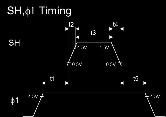
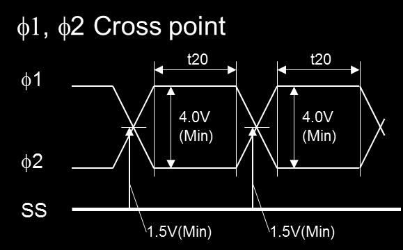
7 TIMING CHART 6
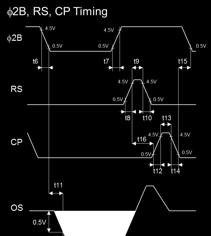
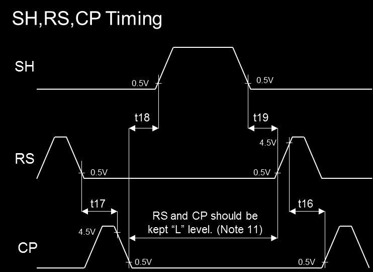
8 TIMING REQUIREMENTS Note 11: RS and CP should be kept L level on this period. 7
9 CHARACTERISTIC SYMBOL MIN TYP. (Note12) MAX UNIT Pulse Timing of SH and 1 Pulses t1, t t8+t12+t13 +t14+t ns Rise/Fall Time of SH Pulse t2, t ns H Level Period of SH Pulse t ns Rise/Fall Time of 2B Pulse t6, t ns Rise/Fall Time of RS Pulse t8, t ns H Level Period of RS Pulse t ns Video Data Delay Time t11 15 ns Rise/Fall Time of CP Pulse t12, t ns H Level Period of CP Pulse t ns Pulse Timing of 2B and CP Pulses t ns t Pulse Timing of RS and CP Pulses ns t Pulse Timing of SH and CP Pulses t ns Pulse Timing of SH and RS Pulses t ns Pulse Timing of 1 and 2 Pulses t20 17 ns Note 12: Typical condition is on the case that f = 1.0MHz. 8
10 CAUTION 1. Window Glass TCD1209DG The dust and stain on the glass window of the package degrade optical performance of CCD sensor. Keep the glass window clean by saturating a cotton swab in alcohol and lightly wiping the surface, and allow the glass to dry, by blowing with filtered dry N2. Care should be taken to avoid mechanical or thermal shock because the glass window is easily to damage. 2. Electrostatic Breakdown Store in shorting clip or in conductive foam to avoid electrostatic breakdown. CCD Image Sensor is protected against static electricity, but interior puncture mode device due to static electricity is sometimes detected. In handing the device, it is necessary to execute the following static electricity preventive measures, in order to prevent the trouble rate increase of the manufacturing system due to static electricity. a. Prevent the generation of static electricity due to friction by making the work with bare hands or by putting on cotton gloves and non-charging working clothes. b. Discharge the static electricity by providing earth plate or earth wire on the floor, door or stand of the work room. c. Ground the tools such as soldering iron, radio cutting pliers of or pincer. It is not necessarily required to execute all precaution items for static electricity. It is all right to mitigate the precautions by confirming that the trouble rate within the prescribed range. 3. Incident Light CCD sensor is sensitive to infrared light. Note that infrared light component degrades resolution and PRNU of CCD sensor. 4. Lead Frame Forming Since this package is not strong against mechanical stress, you should not reform the lead frame. We recommend to use a IC-inserter when you assemble to PCB. 5. Soldering Soldering by the solder flow method cannot be guaranteed because this method may have deleterious effects on prevention of window glass soiling and heat resistance. Using a soldering iron, complete soldering within 10 seconds for lead temperatures of up to 260 C, or within 3 seconds for lead temperatures of up to 350 C. 9
11 PACKAGE DIMENSIONS WDIP22-G H Unit: mm Note 1: 1 st sensing element (S1) to the edge of the package. Note 2: Top of the sensor chip to the bottom of the package. Note 3: Glass thickness (n = 1.5) 10
12 RESTRICTIONS ON PRODUCT USE Toshiba Corporation and its subsidiaries and affiliates are collectively referred to as TOSHIBA. Hardware, software and systems described in this document are collectively referred to as Product. TOSHIBA reserves the right to make changes to the information in this document and related Product without notice. This document and any information herein may not be reproduced without prior written permission from TOSHIBA. Even with TOSHIBA's written permission, reproduction is permissible only if reproduction is without alteration/omission. Though TOSHIBA works continually to improve Product's quality and reliability, Product can malfunction or fail. Customers are responsible for complying with safety standards and for providing adequate designs and safeguards for their hardware, software and systems which minimize risk and avoid situations in which a malfunction or failure of Product could cause loss of human life, bodily injury or damage to property, including data loss or corruption. Before customers use the Product, create designs including the Product, or incorporate the Product into their own applications, customers must also refer to and comply with (a) the latest versions of all relevant TOSHIBA information, including without limitation, this document, the specifications, the data sheets and application notes for Product and the precautions and conditions set forth in the "TOSHIBA Semiconductor Reliability Handbook" and (b) the instructions for the application with which the Product will be used with or for. Customers are solely responsible for all aspects of their own product design or applications, including but not limited to (a) determining the appropriateness of the use of this Product in such design or applications; (b) evaluating and determining the applicability of any information contained in this document, or in charts, diagrams, programs, algorithms, sample application circuits, or any other referenced documents; and (c) validating all operating parameters for such designs and applications. TOSHIBA ASSUMES NO LIABILITY FOR CUSTOMERS' PRODUCT DESIGN OR APPLICATIONS. PRODUCT IS NEITHER INTENDED NOR WARRANTED FOR USE IN EQUIPMENTS OR SYSTEMS THAT REQUIRE EXTRAORDINARILY HIGH LEVELS OF QUALITY AND/OR RELIABILITY, AND/OR A MALFUNCTION OR FAILURE OF WHICH MAY CAUSE LOSS OF HUMAN LIFE, BODILY INJURY, SERIOUS PROPERTY DAMAGE AND/OR SERIOUS PUBLIC IMPACT ("UNINTENDED USE"). Except for specific applications as expressly stated in this document, Unintended Use includes, without limitation, equipment used in nuclear facilities, equipment used in the aerospace industry, medical equipment, equipment used for automobiles, trains, ships and other transportation, traffic signaling equipment, equipment used to control combustions or explosions, safety devices, elevators and escalators, devices related to electric power, and equipment used in finance-related fields. IF YOU USE PRODUCT FOR UNINTENDED USE, TOSHIBA ASSUMES NO LIABILITY FOR PRODUCT. For details, please contact your TOSHIBA sales representative. Do not disassemble, analyze, reverse-engineer, alter, modify, translate or copy Product, whether in whole or in part. Product shall not be used for or incorporated into any products or systems whose manufacture, use, or sale is prohibited under any applicable laws or regulations. The information contained herein is presented only as guidance for Product use. No responsibility is assumed by TOSHIBA for any infringement of patents or any other intellectual property rights of third parties that may result from the use of Product. No license to any intellectual property right is granted by this document, whether express or implied, by estoppel or otherwise. ABSENT A WRITTEN SIGNED AGREEMENT, EXCEPT AS PROVIDED IN THE RELEVANT TERMS AND CONDITIONS OF SALE FOR PRODUCT, AND TO THE MAXIMUM EXTENT ALLOWABLE BY LAW, TOSHIBA (1) ASSUMES NO LIABILITY WHATSOEVER, INCLUDING WITHOUT LIMITATION, INDIRECT, CONSEQUENTIAL, SPECIAL, OR INCIDENTAL DAMAGES OR LOSS, INCLUDING WITHOUT LIMITATION, LOSS OF PROFITS, LOSS OF OPPORTUNITIES, BUSINESS INTERRUPTION AND LOSS OF DATA, AND (2) DISCLAIMS ANY AND ALL EXPRESS OR IMPLIED WARRANTIES AND CONDITIONS RELATED TO SALE, USE OF PRODUCT, OR INFORMATION, INCLUDING WARRANTIES OR CONDITIONS OF MERCHANTABILITY, FITNESS FOR A PARTICULAR PURPOSE, ACCURACY OF INFORMATION, OR NONINFRINGEMENT. Do not use or otherwise make available Product or related software or technology for any military purposes, including without limitation, for the design, development, use, stockpiling or manufacturing of nuclear, chemical, or biological weapons or missile technology products (mass destruction weapons). Product and related software and technology may be controlled under the applicable export laws and regulations including, without limitation, the Japanese Foreign Exchange and Foreign Trade Law and the U.S. Export Administration Regulations. Export and re-export of Product or related software or technology are strictly prohibited except in compliance with all applicable export laws and regulations. Please contact your TOSHIBA sales representative for details as to environmental matters such as the RoHS compatibility of Product. Please use Product in compliance with all applicable laws and regulations that regulate the inclusion or use of controlled substances, including without limitation, the EU RoHS Directive. TOSHIBA ASSUMES NO LIABILITY FOR DAMAGES OR LOSSES OCCURRING AS A RESULT OF NONCOMPLIANCE WITH APPLICABLE LAWS AND REGULATIONS. 11
TCD1209DG TCD1209DG FEATURES PIN CONNECTION. MAXIMUM RATINGS (Note 1) (TOP VIEW)
 (TOP VIEW)") TOSHIBA CCD LINEAR IMAGE SENSOR CCD (Charge Coupled Device) TCD1209DG TCD1209DG The TCD1209DG is a high speed and low dark current 2048 elements CCD image sensor. The sensor is designed for facsimile,
TOSHIBA CCD LINEAR IMAGE SENSOR CCD (Charge Coupled Device) TCD1209DG TCD1209DG The TCD1209DG is a high speed and low dark current 2048 elements CCD image sensor. The sensor is designed for facsimile,
TCD1711DG TCD1711DG. Features. Pin Connection (top view) Maximum Ratings (Note 1)
 Maximum Ratings (Note 1)") TOSHIBA CCD Linear Image Sensor CCD (Charge Coupled Device) TCD7DG TCD7DG The TCD7DG is a high sensitive and low dark current 7450 elements CCD image sensor. The sensor is designed for facsimile, imagescanner
TOSHIBA CCD Linear Image Sensor CCD (Charge Coupled Device) TCD7DG TCD7DG The TCD7DG is a high sensitive and low dark current 7450 elements CCD image sensor. The sensor is designed for facsimile, imagescanner
TCD2557D TCD2557D FEATURES PIN CONNECTION. MAXIMUM RATINGS (Note 1) (TOP VIEW) TOSHIBA CCD LINEAR IMAGE SENSOR CCD (Charge Coupled Device)
 (TOP VIEW) TOSHIBA CCD LINEAR IMAGE SENSOR CCD (Charge Coupled Device)") TOSHIBA CCD LINEAR IMAGE SENSOR CCD (Charge Coupled Device) TCD2557D TCD2557D The TCD2557D is a high sensitive and low dark current 5340 elements 3 line CCD color image sensor which includes CCD drive
TOSHIBA CCD LINEAR IMAGE SENSOR CCD (Charge Coupled Device) TCD2557D TCD2557D The TCD2557D is a high sensitive and low dark current 5340 elements 3 line CCD color image sensor which includes CCD drive
TOSHIBA CCD Linear Image Sensor CCD (charge coupled device) TCD2561D
 TCD2561D") TOSHIBA CCD Linear Image Sensor CCD (charge coupled device) TCD2561D The TCD2561D is a high sensitive and low dark current 5340 elements 4 line CCD color image sensor which includes CCD drive circuit,
TOSHIBA CCD Linear Image Sensor CCD (charge coupled device) TCD2561D The TCD2561D is a high sensitive and low dark current 5340 elements 4 line CCD color image sensor which includes CCD drive circuit,
TCD1501D TCD1501D FEATURES PIN CONNECTION. MAXIMUM RATINGS (Note 1) (TOP VIEW) TOSHIBA CCD LINEAR IMAGE SENSOR CCD (Charge Coupled Device)
 (TOP VIEW) TOSHIBA CCD LINEAR IMAGE SENSOR CCD (Charge Coupled Device)") TOSHIBA CCD LINEAR IMAGE SENSOR CCD (Charge Coupled Device) TCD1501D TCD1501D The TCD1501D which includes sample and hold circuit is a high sensitive and low dark current 5000 elements CCD image sensor.
TOSHIBA CCD LINEAR IMAGE SENSOR CCD (Charge Coupled Device) TCD1501D TCD1501D The TCD1501D which includes sample and hold circuit is a high sensitive and low dark current 5000 elements CCD image sensor.
TOSHIBA CCD LINEAR IMAGE SENSOR CCD(Charge Coupled Device) TCD1205DG
 TCD1205DG") Preliminary TOSHIBA CCD LINEAR IMAGE SENSOR CCD(Charge Coupled Device) TCD1205DG The TCD1205DG is a high sensitive and low dark current 2048 elements linear image sensor. The sensor can be used for POS
Preliminary TOSHIBA CCD LINEAR IMAGE SENSOR CCD(Charge Coupled Device) TCD1205DG The TCD1205DG is a high sensitive and low dark current 2048 elements linear image sensor. The sensor can be used for POS
Preliminary TCD2704D. Features. Pin Connections (top view) Maximum Ratings (Note 1)
 Maximum Ratings (Note 1)") Preliminary TOSHIBA CCD Linear Image Sensor CCD (charge coupled device) T C D 2 7 0 4 D The TCD2704D is a high sensitive and low dark current 7500 elements 4 line CCD color image sensor which includes
Preliminary TOSHIBA CCD Linear Image Sensor CCD (charge coupled device) T C D 2 7 0 4 D The TCD2704D is a high sensitive and low dark current 7500 elements 4 line CCD color image sensor which includes
TOSHIBA CCD Linear Image Sensor CCD (Charge Coupled Device) TCD2564DG
 TCD2564DG") TOSHIBA CCD Linear Image Sensor CCD (Charge Coupled Device) TCD2564DG TCD2564DG The TCD2564DG is a high sensitive and low dark current 5400 elements 3 line CCD color image sensor. The sensor is designed
TOSHIBA CCD Linear Image Sensor CCD (Charge Coupled Device) TCD2564DG TCD2564DG The TCD2564DG is a high sensitive and low dark current 5400 elements 3 line CCD color image sensor. The sensor is designed
TOSHIBA CCD LINEAR IMAGE SENSOR CCD(Charge Coupled Device) TCD1208AP
 TCD1208AP") TOSHIBA CCD LINEAR IMAGE SENSOR CCD(Charge Coupled Device) TCD1208AP TCD1208AP The TCD1208AP is a high sensitive and low dark current 2160 element image sensor. The sensor can be used for facsimile, imagescanner
TOSHIBA CCD LINEAR IMAGE SENSOR CCD(Charge Coupled Device) TCD1208AP TCD1208AP The TCD1208AP is a high sensitive and low dark current 2160 element image sensor. The sensor can be used for facsimile, imagescanner
TOSHIBA CCD LINEAR IMAGE SENSOR CCD(Charge Coupled Device) TCD1304AP
 TCD1304AP") TOSHIBA CCD LINEAR IMAGE SENSOR CCD(Charge Coupled Device) TCD1304AP TCD1304AP The TCD1304AP is a high sensitive and low dark current 3648 elements linear image sensor. The sensor can be used for POS scanner.
TOSHIBA CCD LINEAR IMAGE SENSOR CCD(Charge Coupled Device) TCD1304AP TCD1304AP The TCD1304AP is a high sensitive and low dark current 3648 elements linear image sensor. The sensor can be used for POS scanner.
TOSHIBA Field Effect Transistor Silicon N Channel MOS Type 2SK1829
 TOSHIBA Field Effect Transistor Silicon N Channel MOS Type 2SK1829 High Speed Switching Applications Analog Switch Applications Unit: mm 2.5 V gate drive Low threshold voltage: V th = 0.5 to 1.5 V High
TOSHIBA Field Effect Transistor Silicon P Channel MOS Type 2SJ200
 TOSHIBA Field Effect Transistor Silicon P Channel MOS Type High Power Amplifier Application Unit: mm High breakdown voltage : V DSS = 180 V High forward transfer admittance : Y fs = 4.0 S (typ.) Complementary
TOSHIBA Field Effect Transistor Silicon N Channel MOS Type 2SK2009
 TOSHIBA Field Effect Transistor Silicon N Channel MOS Type 2SK2009 High Speed Switching Applications Analog Switch Applications Unit: mm High input impedance. Low gate threshold voltage: V th = 0.5~1.5
TOSHIBA Transistor Silicon NPN Epitaxial Type (PCT process) 2SC4213
 2SC4213") TOSHIBA Transistor Silicon NPN Epitaxial Type (PCT process) 2SC4213 For Muting and Switching Applications Unit: mm High emitter-base voltage: V EBO = 25 V (min) High reverse h FE : Reverse h FE = 150 (typ.)
TOSHIBA Transistor Silicon NPN Epitaxial Type (PCT process) 2SC4213 For Muting and Switching Applications Unit: mm High emitter-base voltage: V EBO = 25 V (min) High reverse h FE : Reverse h FE = 150 (typ.)
TOSHIBA Transistor Silicon NPN Epitaxial Type (PCT process) 2SC2240
 2SC2240") TOSHIBA Transistor Silicon NPN Epitaxial Type (PCT process) 2SC2240 Low Noise Audio Amplifier Applications Unit: mm The 2SC2240 is a transistor for low frequency and low noise applications. This device
TOSHIBA Transistor Silicon NPN Epitaxial Type (PCT process) 2SC2240 Low Noise Audio Amplifier Applications Unit: mm The 2SC2240 is a transistor for low frequency and low noise applications. This device
SSM3K35CTC SSM3K35CTC. 1. Applications. 2. Features. 3. Packaging and Pin Assignment Rev.3.0. Silicon N-Channel MOS
 MOSFETs Silicon N-Channel MOS 1. Applications High-Speed Switching Analog Switches 2. Features (1) 1.2-V gate drive voltage. (2) Low drain-source on-resistance = 9.0 Ω (max) (@V GS = 1.2 V, I D = 10 ma)
TA75W01FU TA75W01FU. Dual Operational Amplifier. Features Pin Connection (Top View)
") TOSHIBA Bipolar Linear Integrated Circuit Silicon Monolithic TA75W01FU Dual Operational Amplifier Features In the linear mode the input common mode voltage range includes ground. The internally compensated
TOSHIBA Bipolar Linear Integrated Circuit Silicon Monolithic TA75W01FU Dual Operational Amplifier Features In the linear mode the input common mode voltage range includes ground. The internally compensated
TLP3924 TELECOMMUNICATION PROGRAMMABLE CONTROLLERS MOSFET GATE DRIVER. Features. Pin Configuration (top view)
") TOSHIBA PHOTOCOUPLER GaAlAs IRED & PHOTO DIODE ARRAY TELECOMMUNICATION PROGRAMMABLE CONTROLLERS MOSFET GATE DRIVER. Unit: mm φ. The TOSHIBA SSOP coupler is a small outline coupler, suitable for surface
TOSHIBA PHOTOCOUPLER GaAlAs IRED & PHOTO DIODE ARRAY TELECOMMUNICATION PROGRAMMABLE CONTROLLERS MOSFET GATE DRIVER. Unit: mm φ. The TOSHIBA SSOP coupler is a small outline coupler, suitable for surface
TC4069UBP, TC4069UBF, TC4069UBFT
 TOSHIBA CMOS Digital Integrated Circuit Silicon Monolithic TC4069UBP/UBF/UBFT TC4069UBP, TC4069UBF, TC4069UBFT TC4069UB Hex Inverter TC4069UB contains six circuits of inverters. Since the internal circuit
TOSHIBA Field Effect Transistor Silicon N Channel Junction Type 2SK mw
 TOSHIBA Field Effect Transistor Silicon N Channel Junction Type Audio Frequency Low Noise Amplifier Applications Unit: mm Including two devices in SM5 (super mini type with 5 leads.) High Y fs : Y fs =
TC4001BP, TC4001BF, TC4001BFT
 TOSHIBA CMOS Digital Integrated Circuit Silicon Monolithic TC4001BP/BF/BFT TC4001BP, TC4001BF, TC4001BFT TC4001B Quad 2 Input NOR Gate The TC4001B is 2-input positive NOR gate, respectively. Since the
RN4987 RN4987. Switching, Inverter Circuit, Interface Circuit and Driver Circuit Applications. Equivalent Circuit and Bias Resister Values
 TOSHIBA Transistor Silicon NPN/PNP Epitaxial Type (PCT Process) (Transistor with Built-in Bias Resistor) RN4987 RN4987 Switching, Inverter Circuit, Interface Circuit and Driver Circuit Applications Unit:
SSM3K339R SSM3K339R. 1. Applications. 2. Features. 3. Packaging and Pin Assignment Rev.1.0. Silicon N-Channel MOS
 MOSFETs Silicon N-Channel MOS SSM3K339R SSM3K339R 1. Applications Power Management Switches DC-DC Converters 2. Features (1) 1.8-V gate drive voltage. (2) Low drain-source on-resistance : R DS(ON) = 145
HN1B01F HN1B01F. Audio-Frequency General-Purpose Amplifier Applications Q1: Q2: Marking. Q1 Absolute Maximum Ratings (Ta = 25 C)
") TOSHIBA Transistor Silicon PNP Epitaxial Type (PCT Process) Silicon NPN Epitaxial Type (PCT Process) Audio-Frequency General-Purpose Amplifier Applications Q1: High voltage and high current : VCEO = 50
TOSHIBA Transistor Silicon PNP Epitaxial Type (PCT Process) Silicon NPN Epitaxial Type (PCT Process) Audio-Frequency General-Purpose Amplifier Applications Q1: High voltage and high current : VCEO = 50
TOSHIBA INSULATED GATE BIPOLAR TRANSISTOR SILICON N CHANNEL IGBT GT30J322
 TOSHIBA INSULATED GATE BIPOLAR TRANSISTOR SILICON N CHANNEL IGBT GT30J322 GT30J322 FOURTH-GENERATION IGBT CURRENT RESONANCE INVERTER SWITCHING APPLICATIONS Unit: mm FRD included between emitter and collector
SSM6J507NU SSM6J507NU. 1. Applications. 2. Features. 3. Packaging and Pin Assignment Rev Toshiba Corporation
 MOSFETs Silicon P-Channel MOS (U-MOS) 1. Applications Power Management Switches 2. Features (1) 4 V gate drive voltage. (2) Low drain-source on-resistance : R DS(ON) = 20 mω (max) (@V GS = -10 V) R DS(ON)
(Note 1), (Note 2) (Note 1) (Note 1) (Silicon limit) (T c = 25 ) (t = 1 ms) (t = 10 s) (t = 10 s) (Note 3) (Note 4) (Note 5)
, (Note 2) (Note 1) (Note 1) (Silicon limit) (T c = 25 ) (t = 1 ms) (t = 10 s) (t = 10 s) (Note 3) (Note 4) (Note 5)") MOSFETs Silicon N-channel MOS (U-MOS-H) TPN6R003NL TPN6R003NL 1. Applications Switching Voltage Regulators DC-DC Converters 2. Features (1) High-speed switching (2) Small gate charge: Q SW = 4.3 nc (typ.)
MOSFETs Silicon N-channel MOS (U-MOS-H) TPN6R003NL TPN6R003NL 1. Applications Switching Voltage Regulators DC-DC Converters 2. Features (1) High-speed switching (2) Small gate charge: Q SW = 4.3 nc (typ.)
SSM3J356R SSM3J356R. 1. Applications. 2. Features. 3. Packaging and Pin Assignment Rev.3.0. Silicon P-Channel MOS (U-MOS )
") MOSFETs Silicon P-Channel MOS (U-MOS) SSM3J356R SSM3J356R 1. Applications Power Management Switches 2. Features (1) AEC-Q101 qualified (Note 1) (2) 4 V gate drive voltage. (3) Low drain-source on-resistance
MOSFETs Silicon P-Channel MOS (U-MOS) SSM3J356R SSM3J356R 1. Applications Power Management Switches 2. Features (1) AEC-Q101 qualified (Note 1) (2) 4 V gate drive voltage. (3) Low drain-source on-resistance
HN1B04FU HN1B04FU. Audio Frequency General Purpose Amplifier Applications. Marking. Q1 Absolute Maximum Ratings (Ta = 25 C)
") TOSHIBA Transistor Silicon NPN Epitaxial Type (PCT Process) Silicon PNP Epitaxial Type (PCT Process) HN1B04FU Audio Frequency General Purpose Amplifier Applications Unit: mm Q1: High voltage and high current
TOSHIBA Transistor Silicon NPN Epitaxial Type (PCT Process) Silicon PNP Epitaxial Type (PCT Process) HN1B04FU Audio Frequency General Purpose Amplifier Applications Unit: mm Q1: High voltage and high current
SSM6N55NU SSM6N55NU. 1. Applications. 2. Features. 3. Packaging and Pin Configuration Rev.2.0. Silicon N-Channel MOS
 MOSFETs Silicon N-Channel MOS 1. Applications Power Management Switches DC-DC Converters 2. Features (1) 4.5V gate drive voltage. (2) Low drain-source on-resistance : R DS(ON) = 46 mω (max) (@V GS = 10
TC4011BP,TC4011BF,TC4011BFN,TC4011BFT
 TOSHIBA CMOS Digital Integrated Circuit Silicon Monolithic TC4011BP/BF/BFN/BFT TC4011BP,TC4011BF,TC4011BFN,TC4011BFT TC4011B Quad 2 Input NAND Gate The TC4011B is 2-input positive logic NAND gate respectively.
TOSHIBA Transistor Silicon NPN Epitaxial Type (PCT Process) RN1110MFV,RN1111MFV
 RN1110MFV,RN1111MFV") RN0MFV,RNMFV TOSHIBA Transistor Silicon NPN Epitaxial Type (PCT Process) RN0MFV,RNMFV Switching, Inverter Circuit, Interface Circuit and Driver Circuit Applications Ultra-small package, suited to very
RN0MFV,RNMFV TOSHIBA Transistor Silicon NPN Epitaxial Type (PCT Process) RN0MFV,RNMFV Switching, Inverter Circuit, Interface Circuit and Driver Circuit Applications Ultra-small package, suited to very
TC7SB3157CFU TC7SB3157CFU. 1. Functional Description. 2. General. 3. Features. 4. Packaging and Pin Assignment. 5. Marking Rev.4.
 CMOS Digital Integrated Circuits Silicon Monolithic TC7SB3157CFU TC7SB3157CFU 1. Functional Description Single 1-of-2 Multiplexer/Demultiplexer 2. General The TC7SB3157CFU is a high-speed CMOS single 1-of-2
TOSHIBA Field Effect Transistor Silicon N Channel Junction Type 2SK211. Characteristics Symbol Test Condition Min Typ. Max Unit
 TOSHIBA Field Effect Transistor Silicon N Channel Junction Type FM Tuner Applications VHF Band Amplifier Applications Unit: mm Low noise figure: NF = 2.5dB (typ.) (f = 100 MHz) High forward transfer admitance:
TLP206A TLP206A. Measurement Instrument Data Acquisition Programmable Control. Pin Configuration (top view) Internal Circuit
 Internal Circuit") TOSHIBA Photocoupler GaAs IRED & Photo-MOSFET TLP206A Measurement Instrument Data Acquisition Programmable Control Unit: mm The TOSHIBA TLP206A consists of gallium arsenide infrared emitting diode optically
TOSHIBA Photocoupler GaAs IRED & Photo-MOSFET TLP206A Measurement Instrument Data Acquisition Programmable Control Unit: mm The TOSHIBA TLP206A consists of gallium arsenide infrared emitting diode optically
SSM3K341R SSM3K341R. 1. Applications. 2. Features. 3. Packaging and Pin Assignment Rev.5.0. Silicon N-channel MOS (U-MOS -H)
") MOSFETs Silicon N-channel MOS (U-MOS-H) SSM3K341R SSM3K341R 1. Applications Power Management Switches DC-DC Converters 2. Features (1) AEC-Q101 qualified (Note 1) (2) 175 MOSFET (3) 4.0 V drive (4) Low
MOSFETs Silicon N-channel MOS (U-MOS-H) SSM3K341R SSM3K341R 1. Applications Power Management Switches DC-DC Converters 2. Features (1) AEC-Q101 qualified (Note 1) (2) 175 MOSFET (3) 4.0 V drive (4) Low
TOSHIBA Field Effect Transistor Silicon N Channel MOS Type 2SK302
 TOSHIBA Field Effect Transistor Silicon N Channel MOS Type FM Tuner, VHF RF Amplifier Applications Unit: mm Low reverse transfer capacitance: C rss = 0.035 pf (typ.) Low noise figure: NF = 1.7dB (typ.)
TOSHIBA Transistor Silicon PNP Epitaxial Type 2SA2065
 TOSHIBA Transistor Silicon PNP Epitaxial Type 2SA265 High-Speed Switching Applications DC-DC Converter Applications Strobe Applications Unit: mm High DC current gain: h FE = 2 to 5 (I C =.5 A) Low collector-emitter
SSM3J118TU SSM3J118TU. High-Speed Switching Applications. Absolute Maximum Ratings (Ta = 25 C) Electrical Characteristics (Ta = 25 C)
 Electrical Characteristics (Ta = 25 C)") TOSHIBA Field-Effect Transistor Silicon P-Channel MOS Type High-Speed Switching Applications 4 V drive Low ON-resistance: R on = 48 mω (max) (@V GS = 4 V) R on = 24 mω (max) (@V GS = V) Absolute Maximum
TOSHIBA Field-Effect Transistor Silicon P-Channel MOS Type High-Speed Switching Applications 4 V drive Low ON-resistance: R on = 48 mω (max) (@V GS = 4 V) R on = 24 mω (max) (@V GS = V) Absolute Maximum
RN2101MFV, RN2102MFV, RN2103MFV RN2104MFV, RN2105MFV, RN2106MFV
 RN21MFV TOSHIBA Transistor Silicon PNP Epitaxial Type (PCT Process) (Bias Resistor built-in Transistor) RN21MFV, RN22MFV, RN23MFV,, Switching, Inverter Circuit, Interface Circuit and Driver Circuit Applications
SSM3K357R SSM3K357R. 1. Applications. 2. Features. 3. Packaging and Pin Assignment Rev.2.0. Silicon N-Channel MOS.
 MOSFETs Silicon N-Channel MOS SSM3K357R SSM3K357R 1. Applications Relay Drivers 2. Features (1) AEC-Q101 Qualified (Note1). (2) 3.0-V gate drive voltage. (3) Built-in Internal Zener diodes and resistors.
TC7MBL3245AFT, TC7MBL3245AFK
 TOSHIBA CMOS Digital Integrated Circuit Silicon Monolithic TC7MBL3245AFT/FK TC7MBL3245AFT, TC7MBL3245AFK Octal Low Voltage Bus Switch The TC7MBL3245A provides eight bits of low-voltage, high-speed bus
TOSHIBA Original CMOS 16-Bit Microcontroller. TLCS-900/H Series TMP95C061BFG TMP95C061BDFG. Semiconductor Company
 TOSHIBA Original CMOS 16-Bit Microcontroller TLCS-900/H Series TMP95C061BFG TMP95C061BDFG Semiconductor Company TMP95C061B Document Change Notification The purpose of this notification is to inform customers
(Note 1,2) (Note 1,3) (Note 1) (Silicon limit) (t = 1 ms) (T c = 25 ) (Note 4)
 (Note 1,3) (Note 1) (Silicon limit) (t = 1 ms) (T c = 25 ) (Note 4)") MOSFETs Silicon N-channel MOS (U-MOS-H) TKE10N1 TKE10N1 1. Applications Switching Voltage Regulators 2. Features (1) Low drain-source on-resistance: R DS(ON) = 2.8 mω (typ.) (V GS = 10 V) (2) Low leakage
MOSFETs Silicon N-channel MOS (U-MOS-H) TKE10N1 TKE10N1 1. Applications Switching Voltage Regulators 2. Features (1) Low drain-source on-resistance: R DS(ON) = 2.8 mω (typ.) (V GS = 10 V) (2) Low leakage
TC75W57FU, TC75W57FK
 Dual Comparator TOSHIBA CMOS Linear Integrated Circuit Silicon Monolithic TC75W57FU, TC75W57FK TC75W57FU/FK TC75W57 is a CMOS type general-purpose dual comparator capable of single power supply operation
TLP206A TLP206A. Measurement Instrument Data Acquisition Programmable Control. Pin Configuration (top view) Internal Circuit
 Internal Circuit") TOSHIBA Photocoupler GaAs IRED & Photo-MOSFET TLP206A Measurement Instrument Data Acquisition Programmable Control Unit: mm The TOSHIBA TLP206A consists of gallium arsenide infrared emitting diode optically
TOSHIBA Photocoupler GaAs IRED & Photo-MOSFET TLP206A Measurement Instrument Data Acquisition Programmable Control Unit: mm The TOSHIBA TLP206A consists of gallium arsenide infrared emitting diode optically
TOSHIBA Transistor Silicon PNP Epitaxial Type 2SA2060
 TOSHIBA Transistor Silicon PNP Epitaxial Type 2SA26 High-Speed Switching Applications DC-DC Converter Applications Strobe Applications Unit: mm High DC current gain: h FE = 2 to 5 (I C =.3 A) Low collector-emitter
TC7W04FU, TC7W04FK TC7W04FU/FK. 3 Inverters. Features. Marking TOSHIBA CMOS Digital Integrated Circuit Silicon Monolithic
 TOSHIBA CMOS Digital Integrated Circuit Silicon Monolithic TC7W04FU, TC7W04FK TC7W04FU/FK 3 Inverters The TC7W04 is a high speed C 2 MOS Buffer fabricated with silicon gate C 2 MOS technology. The internal
Bipolar Transistors. Bipolar Transistors Application Note. Description
 Bipolar Transistors Description This document describes the terms used in data sheets bipolar transistors. 1 218-7-1 Table of Contents Description... 1 Table of Contents... 2 1. Glossary... 3 1.1. Absolute
TC4093BP, TC4093BF TC4093BP/BF. TC4093B Quad 2-Input NAND Schmitt Triggers. Pin Assignment. Logic Diagram
 TOSHIBA CMOS Digital Integrated Circuit Silicon Monolithic TC4093BP, TC4093BF TC4093B Quad 2-Input NAND Schmitt Triggers The TC4093B is a quad 2-input NAND gate having Schmitt trigger function for all
TOSHIBA Multi-Chip Transistor Silicon NPN / PNP Epitaxial Type TPC6901A. Rating Unit. P C (Note 2) 500 mw. (Note 2) (Note 2) R th (j-a) (Note 2)
 500 mw. (Note 2) (Note 2) R th (j-a) (Note 2)") TPC69A TOSHIBA Multi-Chip Transistor Silicon NPN / PNP Epitaxial Type TPC69A High-Speed Switching Applications MOS Gate Drive Applications Unit: mm NPN and PNP transistors are mounted on a compact and
TPC69A TOSHIBA Multi-Chip Transistor Silicon NPN / PNP Epitaxial Type TPC69A High-Speed Switching Applications MOS Gate Drive Applications Unit: mm NPN and PNP transistors are mounted on a compact and
TLP3215. Measuring Instruments Logic IC Testers / Memory Testers Board Testers / Scanners. Features. Pin Configuration (Top View)
") TLP5 TOSHIBA PHOTOCOUPLER PHOTO RELAY TLP5 Measuring Instruments Logic IC Testers / Memory Testers Board Testers / Scanners. φ. Unit: mm The TOSHIBA TLP5 is an ultra-small photorelay suitable for surface-mount
TLP5 TOSHIBA PHOTOCOUPLER PHOTO RELAY TLP5 Measuring Instruments Logic IC Testers / Memory Testers Board Testers / Scanners. φ. Unit: mm The TOSHIBA TLP5 is an ultra-small photorelay suitable for surface-mount
TLP127 TLP127. Programmable Controllers DC Output Module Telecommunication. Pin Configurations (top view)
") TOSHIBA Photocoupler GaAs Ired & Photo Transistor TLP27 Programmable Controllers DC Output Module Telecommunication Unit: mm The TOSHIBA mini-flat coupler TLP27 is a small outline coupler, suitable for
TOSHIBA Photocoupler GaAs Ired & Photo Transistor TLP27 Programmable Controllers DC Output Module Telecommunication Unit: mm The TOSHIBA mini-flat coupler TLP27 is a small outline coupler, suitable for
TC7W00FU, TC7W00FK TC7W00FU/FK. Dual 2-Input NAND Gate. Features. Marking. Pin Assignment (top view)
") TOSHIBA CMOS Digital Integrated Circuit Silicon Monolithic TC7W00FU, TC7W00FK TC7W00FU/FK Dual 2-Input NAND Gate Features High Speed : t pd = 6ns (typ.) at V CC = 5V Low power dissipation : I CC = 1μA
TOSHIBA CMOS Digital Integrated Circuit Silicon Monolithic TC7W00FU, TC7W00FK TC7W00FU/FK Dual 2-Input NAND Gate Features High Speed : t pd = 6ns (typ.) at V CC = 5V Low power dissipation : I CC = 1μA
TLP3543 TLP Applications. 2. General. 3. Features. 4. Packaging and Pin Assignment Rev.3.0. Start of commercial production
 Photocouplers Photorelay TLP343 TLP343. Applications Mechanical relay replacements Security Systems Measuring Instruments Factory Automation (FA) Amusement Equipment 2. General The TLP343 photorelay consists
TPW1R005PL TPW1R005PL. 1. Applications. 2. Features. 3. Packaging and Internal Circuit Rev Toshiba Corporation
 MOSFETs Silicon N-channel MOS (U-MOS-H) TPW1R005PL TPW1R005PL 1. Applications High-Efficiency DC-DC Converters Switching Voltage Regulators Motor Drivers 2. Features (1) High-speed switching (2) Small
TOSHIBA Schottky Barrier Rectifier Schottky Barrier Type CMS (Note 1)
") TOSHIBA Schottky Barrier Rectifier Schottky Barrier Type CMS06 Switching Mode Power Supply Applications Portable Equipment Battery Applications Unit: mm Forward voltage: V FM = 0.37 V (max) Average forward
TOSHIBA Schottky Barrier Rectifier Schottky Barrier Type CMS06 Switching Mode Power Supply Applications Portable Equipment Battery Applications Unit: mm Forward voltage: V FM = 0.37 V (max) Average forward
TOSHIBA Field Effect Transistor Silicon N Channel MOS Type SSM3K16FU
 SSMKFU TOSHIBA Field Effect Transistor Silicon N Channel MOS Type SSMKFU High Speed Switching Applications Analog Switching Applications Unit: mm Suitable for high-density mounting due to compact package
TOSHIBA Transistor Silicon PNP / NPN Epitaxial Type (PCT Process) HN4B101J. Rating Unit PNP NPN. DC (Note 1) I C A Pulse (Note 1) I CP
 HN4B101J. Rating Unit PNP NPN. DC (Note 1) I C A Pulse (Note 1) I CP") TOSHIBA Transistor Silicon PNP / NPN Epitaxial Type (PCT Process) MOS Gate Drive Applications Switching Applications Small footprint due to a small and thin package High DC current gain : h FE = 2 to 5
TOSHIBA Transistor Silicon PNP / NPN Epitaxial Type (PCT Process) MOS Gate Drive Applications Switching Applications Small footprint due to a small and thin package High DC current gain : h FE = 2 to 5
TOSHIBA Field Effect Transistor Silicon P Channel MOS Type SSM3J01T. A Pulse. 3.4 (Note 2) 1250 mw
 1250 mw") SSMJT TOSHIBA Field Effect Transistor Silicon P Channel MOS Type SSMJT Power Management Switch High Speed Switching Applications Unit: mm Small Package Low on Resistance : R on =.4 Ω (max) (@V GS = ) :
SSMJT TOSHIBA Field Effect Transistor Silicon P Channel MOS Type SSMJT Power Management Switch High Speed Switching Applications Unit: mm Small Package Low on Resistance : R on =.4 Ω (max) (@V GS = ) :
TOSHIBA Field-Effect Transistor Silicon N-Channel MOS Type SSM3K35MFV. DC I D 180 ma Pulse I DP 360
 SSMKMFV TOSHIBA Field-Effect Transistor Silicon N-Channel MOS Type SSMKMFV High-Speed Switching Applications Analog Switch Applications Unit: mm. V drive Low ON-resistance : R on = Ω (max) (@V GS =. V)
TOSHIBA Transistor Silicon PNP Triple Diffused Type 2SA2142
 TOSHIBA Transistor Silicon PNP Triple Diffused Type 2SA242 High-Voltage Switching Applications Unit: mm High breakdown voltage: V CEO = 6 V Absolute Maximum Ratings (Ta = ) Characteristic Symbol Rating
TLP3341 TLP Applications. 2. General. 3. Features. 4. Packaging and Pin Configuration Rev.3.0
 Photocouplers Photorelay TLP3341 TLP3341 1. Applications High-Speed Memory Testers High-Speed Logic IC Testers Radio-Frequency Measuring Instruments ATE (Automatic Test Equipment) 2. General The TLP3341
TOSHIBA CMOS Digital Integrated Circuit Silicon Monolithic TC7S14F, TC7S14FU
 TOSHIBA CMOS Digital Integrated Circuit Silicon Monolithic TC7S14F, TC7S14FU Schmitt Inverter The TC7S14 is a high speed C 2 MOS Schmitt Inverter fabricated with silicon gate C 2 MOS technology. It achieves
SSM3K36FS N X SSM3K36FS. High-Speed Switching Applications. Equivalent Circuit (top view) Absolute Maximum Ratings (Ta = 25 C)
 Absolute Maximum Ratings (Ta = 25 C)") TOSHIBA Field-Effect Transistor Silicon N Channel MOS Type High-Speed Switching Applications.5-V drive Low ON-resistance : R on =.5 Ω (max) (@V GS =.5 V) : R on =.4 Ω (max) (@V GS =.8 V) : R on =.85 Ω
TOSHIBA Field-Effect Transistor Silicon N Channel MOS Type High-Speed Switching Applications.5-V drive Low ON-resistance : R on =.5 Ω (max) (@V GS =.5 V) : R on =.4 Ω (max) (@V GS =.8 V) : R on =.85 Ω
TOSHIBA Field Effect Transistor Silicon N Channel MOS Type SSM3K37FS. JEDEC Storage temperature range T stg 55 to 150 C
 TOSHIBA Field Effect Transistor Silicon N Channel MOS Type High Speed Switching Applications Analog Switch Applications Unit: mm.vdrive Low ON-resistance R DS(ON) =.6 Ω (max) (@V GS =. V) R DS(ON) =. Ω
TOSHIBA Schottky Barrier Diode CRS12
 CRS2 TOSHIBA Schottky Barrier Diode CRS2 Switching Mode Power Supply Applications (Output voltage: 2 V) / Converter Applications Unit: mm Forward voltage: V FM =.58 V (max) Average forward current: I F
TOSHIBA Schottky Barrier Diode CMS14
 TOSHIBA Schottky Barrier Diode CMS4 Switching Mode Power Supply Applications (Output voltage: 2 V) / Converter Applications Unit: mm Forward voltage: V FM =.58 V (max) Average forward current: I F (AV)
TOSHIBA Field Effect Transistor Silicon N Channel MOS Type (L 2 -π-mos V) 2SK2963
 2SK2963") TOSHIBA Field Effect Transistor Silicon N Channel MOS Type (L 2 -π-mos V) 2SK2963 2SK2963 DC-DC Converter, Relay Drive and Motor Drive Applications Unit: mm 4-V gate drive Low drain-source ON-resistance:
TOSHIBA Field Effect Transistor Silicon N Channel MOS Type (L 2 -π-mos V) 2SK2963 2SK2963 DC-DC Converter, Relay Drive and Motor Drive Applications Unit: mm 4-V gate drive Low drain-source ON-resistance:
TOSHIBA Schottky Barrier Diode CMS14
 TOSHIBA Schottky Barrier Diode CMS4 Switching Mode Power Supply Applications (Output voltage: 2 V) / Converter Applications Unit: mm Forward voltage: V FM =.58 V (max) Average forward current: I F (AV)
TOSHIBA Transistor Silicon PNP / NPN Epitaxial Type (PCT Process) HN4B102J. Rating
 HN4B102J. Rating") HN4BJ TOSHIBA Transistor Silicon PNP / NPN Epitaxial Type (PCT Process) HN4BJ MOS Gate Drive Applications Switching Applications Small footprint due to a small and thin package High DC current gain : PNP
HN4BJ TOSHIBA Transistor Silicon PNP / NPN Epitaxial Type (PCT Process) HN4BJ MOS Gate Drive Applications Switching Applications Small footprint due to a small and thin package High DC current gain : PNP
TOSHIBA Field Effect Transistor Silicon N Channel MOS Type SSM3K17FU
 SSMK7FU TOSHIBA Field Effect Transistor Silicon N Channel MOS Type SSMK7FU High Speed Switching Applications Analog Switch Applications Unit: mm Suitable for high-density mounting due to compact package
TLP191B TLP191B. Telecommunication Programmable Controllers MOS Gate Driver MOS FET Gate Driver. TOSHIBA Photocoupler GaAlAs IRED & Photo-Diode Array
 TLP9B TOSHIBA Photocoupler GaAlAs IRED & Photo-Diode Array TLP9B Telecommunication Programmable Controllers MOS Gate Driver MOS FET Gate Driver Unit: mm The TOSHIBA mini-flat coupler TLP9B is a small outline
TK4P60DB TK4P60DB. 1. Applications. 2. Features. 3. Packaging and Internal Circuit Rev.1.0. Silicon N-Channel MOS (π-mos )
") MOSFETs Silicon N-Channel MOS (π-mos) TK4P60DB TK4P60DB 1. Applications Switching Voltage Regulators 2. Features (1) Low drain-source on-resistance : R DS(ON) = 1.6 Ω (typ.) (2) High forward transfer admittance
MOSFETs Silicon N-Channel MOS (π-mos) TK4P60DB TK4P60DB 1. Applications Switching Voltage Regulators 2. Features (1) Low drain-source on-resistance : R DS(ON) = 1.6 Ω (typ.) (2) High forward transfer admittance
(Note 1) (Note 1) (Note 2) (Note 1) (Note 1)
 (Note 1) (Note 2) (Note 1) (Note 1)") MOSFETs Silicon N-Channel MOS (DTMOS-H) TK31E60X TK31E60X 1. Applications Switching Voltage Regulators 2. Features (1) Low drain-source on-resistance: R DS(ON) = 0.073 Ω (typ.) by used to Super Junction
MOSFETs Silicon N-Channel MOS (DTMOS-H) TK31E60X TK31E60X 1. Applications Switching Voltage Regulators 2. Features (1) Low drain-source on-resistance: R DS(ON) = 0.073 Ω (typ.) by used to Super Junction
TOSHIBA Transistor Silicon NPN Epitaxial Planar Type 2SC5086. Characteristics Symbol Test Condition Min Typ. Max Unit
 TOSHIBA Transistor Silicon NPN Epitaxial Planar Type 2SC5086 VHF~UHF Band Low Noise Amplifier Applications Unit: mm Low noise figure, high gain. NF = 1.1dB, S 21e 2 = 11dB (f = 1 GHz) Absolute Maximum
TOSHIBA Field Effect Transistor Silicon N Channel MOS Type (L 2 π MOSV) 2SK2615
 2SK2615") TOSHIBA Field Effect Transistor Silicon N Channel MOS Type (L 2 π MOSV) 2SK2615 2SK2615 DC DC Converter, Relay Drive and Motor Drive Applications Unit: mm Low drain source ON resistance : R DS (ON) = 0.23
TOSHIBA Field Effect Transistor Silicon N Channel MOS Type (L 2 π MOSV) 2SK2615 2SK2615 DC DC Converter, Relay Drive and Motor Drive Applications Unit: mm Low drain source ON resistance : R DS (ON) = 0.23
TLP3902 TLP3902 SOLID STATE RELAY PROGRAMMABLE CONTROLLERS MOSFET GATE DRIVER. Features. Pin Configuration (top view)
") TOSHIBA PHOTOCOUPLER GaAs IRED & PHOTO-DIODE ARRAY TLP92 SOLID STATE RELAY PROGRAMMABLE CONTROLLERS MOSFET GATE DRIVER Unit: mm The TOSHIBA mini flat coupler TLP92 is a small outline coupler, suitable
TOSHIBA PHOTOCOUPLER GaAs IRED & PHOTO-DIODE ARRAY TLP92 SOLID STATE RELAY PROGRAMMABLE CONTROLLERS MOSFET GATE DRIVER Unit: mm The TOSHIBA mini flat coupler TLP92 is a small outline coupler, suitable
TC75S56F, TC75S56FU, TC75S56FE
 TOSHIBA CMOS Linear Integrated Circuit Silicon Monolithic TC75S56F/FU/FE TC75S56F, TC75S56FU, TC75S56FE Single Comparator The TC75S56F/TC75S56FU/TC75S56FE is a CMOS generalpurpose single comparator. The
TOSHIBA Transistor Silicon NPN Epitaxial Type (PCT Process) 2SC2705
 2SC2705") TOSHIBA Transistor Silicon NPN Epitaxial Type (PCT Process) Audio Frequency Amplifier Applications Unit: mm Small collector output capacitance: C ob =.8 pf (typ.) High transition frequency: f T = 2 MHz
TOSHIBA Transistor Silicon NPN Epitaxial Type (PCT Process) Audio Frequency Amplifier Applications Unit: mm Small collector output capacitance: C ob =.8 pf (typ.) High transition frequency: f T = 2 MHz
TC7USB40FT TC7USB40FT. 1. Functional Description. 2. General. 3. Features. 4. Packaging and Pin Assignment Rev.2.0. Dual SPDT USB Switch
 CMOS Digital Integrated Circuits TC7USB40FT Silicon Monolithic TC7USB40FT 1. Functional Description Dual SPDT USB Switch 2. General The TC7USB40FT is high-speed CMOS dual 1-2 multiplexer/demultiplexer.
TOSHIBA Schottky Barrier Rectifier Schottky Barrier Type CMS04. Junction temperature T j 40~125 C JEITA
 CMS4 TOSHIBA Schottky Barrier Rectifier Schottky Barrier Type CMS4 Switching Mode Power Supply Applications Portable Equipment Battery Applications Unit: mm Forward voltage: V FM =.37 V (max) Average forward
TOSHIBA Field-Effect Transistor Silicon N-Channel MOS Type SSM3K35MFV. DC I D 180 ma Pulse I DP 360
 SSMKMFV TOSHIBA Field-Effect Transistor Silicon N-Channel MOS Type SSMKMFV High-Speed Switching Applications Analog Switch Applications Unit: mm. V drive Low ON-resistance : R on = Ω (max) (@V GS =. V)
RN2101, RN2102, RN2103, RN2104, RN2105, RN2106
 TOSHIBA Transistor Silicon PNP Epitaxial Type (PCT Process) RN2101,,,,, RN2101 Switching, Inverter Circuit, Interface Circuit and Driver Circuit Applications Unit: mm Built-in bias resistors Simplified
TOSHIBA Transistor Silicon NPN Epitaxial Type (PCT process) 2SC3303. TOSHIBA 2-7J1A temperature/current/voltage and the significant change in
 2SC3303. TOSHIBA 2-7J1A temperature/current/voltage and the significant change in") SC TOSHIBA Transistor Silicon NPN Epitaxial Type (PCT process) SC High Current Switching Applications DC-DC Converter Applications Industrial Applications Unit: mm Low collector saturation voltage: V CE
SC TOSHIBA Transistor Silicon NPN Epitaxial Type (PCT process) SC High Current Switching Applications DC-DC Converter Applications Industrial Applications Unit: mm Low collector saturation voltage: V CE
TC4584BP, TC4584BF TC4584BP/BF. TC4584B Hex Schmitt Trigger. Pin Assignment. Logic Diagram. Input/Output Voltage Characteristic
 TC484BP/BF TC484B Hex Schmitt Trigger TOSHIBA CMOS Digital Integrated Circuit Silicon Monolithic TC484BP, TC484BF The TC484B is the 6-circuit inverter having the Schmitt trigger function at the input terminal.
TOSHIBA Field Effect Transistor Silicon N-Channel Dual Gate MOS Type 3SK292
 TOSHIBA Field Effect Transistor Silicon N-Channel Dual Gate MOS Type 3SK292 TV Tuner, VHF RF Amplifier Application Unit: mm Superior cross modulation performance. Low reverse transfer capacitance: C rss
TLX9185A. Pin Configuration TOSHIBA Photocoupler IRLED & Photo-Transistor. Unit: mm
 TLX985A TOSHIBA Photocoupler IRLED & Photo-Transistor TLX985A 〇 Various Controllers 〇 Signal transmission between different circuit potential 〇 HEV (Hybrid Electric Vehicle) and EV (Electric Vehicle) Applications
TOSHIBA Transistor Silicon PNP Triple Diffused Type 2SA2142
 TOSHIBA Transistor Silicon PNP Triple Diffused Type 2SA242 High-Voltage Switching Applications Unit: mm High breakdown voltage: V CEO = 6 V Absolute Maximum Ratings (Ta = ) Characteristic Symbol Rating
TOSHIBA Field Effect Transistor Silicon N Channel MOS Type 2SK3078A
 TOSHIBA Field Effect Transistor Silicon N Channel MOS Type VHF/UHF Band Amplifier Applications (Note)The TOSHIBA products listed in this document are intended for high frequency Power Amplifier of telecommunications
TOSHIBA Transistor Silicon NPN Triple Diffused Mesa Type 2SC5201
 2SC52 TOSHIBA Transistor Silicon NPN Triple Diffused Mesa Type 2SC52 High-Voltage Switching Applications Unit: mm High breakdown voltage: V CEO = 6 V Low saturation voltage: V CE (sat) =. V (max) (I C
(Note 1) (Note 1) (Note 2) (Note 3) (Note 4) (t = 10 s) (t = 10 s)
 (Note 1) (Note 2) (Note 3) (Note 4) (t = 10 s) (t = 10 s)") MOSFETs Silicon P-Channel MOS (U-MOS) TPC8132 TPC8132 1. Applications Lithium-Ion Secondary Batteries Power Management Switches 2. Features (1) Small footprint due to small and thin package (2) Low drain-source
MOSFETs Silicon P-Channel MOS (U-MOS) TPC8132 TPC8132 1. Applications Lithium-Ion Secondary Batteries Power Management Switches 2. Features (1) Small footprint due to small and thin package (2) Low drain-source
TOSHIBA Schottky Barrier Rectifier Schottky Barrier Type CRS (50 Hz) 22 (60 Hz)
 22 (60 Hz)") CRS TOSHIBA Schottky Barrier Rectifier Schottky Barrier Type CRS High Speed Rectifier Applications Unit: mm Low forward voltage: V FM =.37 V @ I FM =.7 A Average forward current: I F (AV) =. A Repetitive
CRS TOSHIBA Schottky Barrier Rectifier Schottky Barrier Type CRS High Speed Rectifier Applications Unit: mm Low forward voltage: V FM =.37 V @ I FM =.7 A Average forward current: I F (AV) =. A Repetitive
Note: The product(s) described herein should not be used for any other application.
 described herein should not be used for any other application.") Discrete IGBTs Silicon N-Channel IGBT GT40QR21 GT40QR21 1. Applications Dedicated to Voltage-Resonant Inverter Switching Applications Note: The product(s) described herein should not be used for any other
Discrete IGBTs Silicon N-Channel IGBT GT40QR21 GT40QR21 1. Applications Dedicated to Voltage-Resonant Inverter Switching Applications Note: The product(s) described herein should not be used for any other
TOSHIBA Schottky Barrier Rectifier Schottky Barrier Type CMS (Ta = 34 C) 2.0 (Tl = 119 C) JEDEC Storage temperature T stg 40~150 C
 2.0 (Tl = 119 C) JEDEC Storage temperature T stg 40~150 C") TOSHIBA Schottky Barrier Rectifier Schottky Barrier Type CMS Switching Mode Power Supply Applications Portable Equipment Battery Applications Unit: mm Forward voltage: V FM =.55 V (max) Average forward
TOSHIBA Schottky Barrier Rectifier Schottky Barrier Type CMS Switching Mode Power Supply Applications Portable Equipment Battery Applications Unit: mm Forward voltage: V FM =.55 V (max) Average forward
TOSHIBA Field-Effect Transistor Silicon N Channel MOS Type SSM3K7002F
 SSMK7F TOSHIBA Field-Effect Transistor Silicon N Channel MOS Type SSMK7F High-Speed Switching Applications Analog Switch Applications Unit: mm Small package Low ON-resistance : R on =. Ω (max) (@V GS =.
TOSHIBA Transistor Silicon NPN Epitaxial Type 2SC3225. JEITA Storage temperature range T stg 55 to 150 C
 2SC22 TOSHIBA Transistor Silicon NPN Epitaxial Type 2SC22 Switching Applications Solenoid Drive Applications Industrial Applications Unit: mm High DC current gain: h FE = (min) (I C = 4 ma) Low collector-emitter
TC7SBL66CFU, TC7SBL384CFU
 TOSHIBA CMOS Digital Integrated Circuit Silicon Monolithic TC7SBL66C,384CFU TC7SBL66CFU, TC7SBL384CFU Low Voltage / Low Capacitance Single Bus Switch The TC7SBL66C and TC7SBL384C are a Low Voltage / Low
4. Absolute Maximum Ratings (Note) (Unless otherwise specified, T a = 25 ) Symbol V RRM I F(DC) I FP. I 2 t. T j T stg TOR
 (Unless otherwise specified, T a = 25 ) Symbol V RRM I F(DC) I FP. I 2 t. T j T stg TOR") SiC Schottky Barrier Diode TRS12N65D TRS12N65D 1. Applications Power Factor Correction Solar Inverters Uninterruptible Power Supplies DC-DC Converters 2. Features (1) Forward DC current(/) I F(DC) = 6/12
SiC Schottky Barrier Diode TRS12N65D TRS12N65D 1. Applications Power Factor Correction Solar Inverters Uninterruptible Power Supplies DC-DC Converters 2. Features (1) Forward DC current(/) I F(DC) = 6/12
TOSHIBA Field Effect Transistor Silicon N-Channel Dual Gate MOS Type 3SK294
 TOSHIBA Field Effect Transistor Silicon N-Channel Dual Gate MOS Type TV Tuner, VHF RF Amplifier Application Unit: mm Superior cross modulation performance Low reverse transfer capacitance: C rss = 20 ff