User Manual. Data Acquisition Modules/ Distributed IO Modules
|
|
|
- Victoria Harmon
- 5 years ago
- Views:
Transcription


1 User Manual Data Acquisition Modules/ Distributed IO Modules UMIOE Rev 5.0, 10/2009
2 COPYRIGHT NOTICE This manual is a publication of Brainchild Electronics Co.. Ltd. and is provided for use by its customers only. The contents of the manual are copyrighted by Brainchild Electronics; reproduction in whole or in part, for use other than in support of Brainchild Electronics equipment, is prohibited without the specific written permission from Brainchild Electronics SERVICE If service is required then pack the unit in its original packaging container or, if unavailable, any suitable rigid container. If a substitute container is used, surround the unit with shock absorbing material; damage in shipment is not covered by the warranty. Include a letter with the unit describing the difficulty of usage and request Brainchild for RMA procedure. Send the equipment to the following address: Brainchild Electronic. Co. Ltd 6F, 209, Chung yong Road, Nan Kang Dist, Taipei, Taiwan, R.O.C Tel: Fax: sales@brainchild.com.tw All returns will be tested to verify customer claims of noncompliance with the product warranty. Improper return packaging, which makes verification impossible, will void the warranty. If noncompliance is verified and is not due to customer abuse or the other exceptions described with product warranty, Brainchild Electronics will, at its option, repair or replace the Product returned to it, freight prepaid, which fail to comply with the foregoing warranty, provided Brainchild is notified of such noncompliance within the one-year warranty period. ASSISTANCE This manual is designed to provide the necessary information for trouble-free installation and operation of your new IO Series. However, if you need assistance, please call Brainchild Electronic Co. Ltd. at Ext 613 or visit our web site at www. Brainchild.com.tw MANUAL REVISION If you contact us in reference to this manual, please include the following document number Name: User Manual for IO modules Document: UMIOB, 08, 2007 Revision: 2.0 Warranty Certificate For New product: This product is warranted against defects in materials and workmanship for a period of 12 months from the date of shipment to Buyer. For Rectified Products: Any product that will be replaced will have Warranty for 6 months or up to Original Product Warranty period whichever is greater. The warranty is limited to repair or replacement of the defective unit at the option of the manufacturer. This warranty is void if the product has been altered, misused, dismantled, or otherwise abused. 2
3 ALL OTHER WARRANTIES, EXPRESSED OR IMPLIED, ARE EXCLUDED, INCLUDING BUT NOT LIMITED TO THE IMPLIED WARRANTIES OF MERCHANTABILITY AND FITNESS FOR A PARTICULAR PURPOSE. MAINTENANCE & SERVICE There are no parts that can be serviced by the user. Service should be performed on a unit substitution basis only. Do not attempt to remove, replace or service any printed circuit board, components or any hardware/software related with display product. If problem within the display product occurs, contact the factory for service information or repair. Any Mechanical or Electrical Modification to this Unit will void all Warranties DISCLAIMER Information contained herein are subject to change without notice. Every precaution has been taken in the preparation of this manual. Nevertheless, Brainchild Electronics assumes no responsibility, express or implied, for errors or omissions or any damages resulting from the use of the information contained in this publication. All trademarks belong to their respective owners 3
4 TABLE OF CONTENTS 1. AN OVERVIEW OF THE IO SYSTEM INTRODUCTION APPLICATION CONFIGURATIONS I/O Expansion Data Acquisition MODULE SELECTION TABLE IO GENERAL INFORMATION PHYSICAL DIMENSIONS GROUNDING/SHIELDING NETWORK TERMINATION RS485 NETWORKING SETTING THE MODBUS NODE ID Node ID Table DIP Switch Status Register COMMUNICATIONS SETTINGS Communications Settings with DIP Switch 10 OFF (Default) Communications Settings with DIP Switch 10 ON (Programmed Baud Rate) Communications Settings Registers Modbus Register Types IO MODULES IO-16DI - DIGITAL INPUTS WITH COUNTERS Description Technical Specification of IO-16DI Status Indicators Wiring Switch Settings IO-16DI Data Registers (MODULE TYPE = 100) IO-16DO - DIGITAL OUTPUTS Description Technical Specification of IO-16DO Status Indicators Wiring Switch Setting IO-16DO Data Registers (MODULE TYPE = 101) IO-4RO - RELAY OUTPUTS Description Technical Specification of IO-4RO Status Indicators Wiring Switch Setting IO-4RO Data Registers (MODULE TYPE = 113) IO-8DIO - DIGITAL INPUTS / OUTPUTS Description Technical Specification of IO-DIO Status Indicators Wiring Switch Settings Jumper Settings IO-8DIO Data Registers (MODULE TYPE = 102) IO-8AII AND IO-8AIV - ANALOG INPUTS Description Technical Specification of IO-8AI Status Indicators Wiring
5 3.5.5 Switch Settings IO-8AI Data Registers (IO8AII TYPE = 103 / IO-8AIV TYPE = 104) IO-8AIIS AND IO-8AIVS - ISOLATED ANALOG INPUTS Description Technical Specification of IO-8AIIS and IO-8AIVS Status Indicators Wiring Switch Settings IO-8AIIS Data Registers (8AII TYPE = 107/8AIV TYPE = 108) IO-8TC - THERMOCOUPLE INPUTS Description Technical Specification of IO-8TC Status Indicators Wiring Switch Settings IO-8TC Data Registers (MODULE TYPE = 105) IO-8TCS - ISOLATED THERMOCOUPLE INPUTS Description Technical Specification of IO-8TCS Status Indicators Wiring Switch Settings IO-8TCS Data Registers (MODULE TYPE = 106) IO-6RTD - RTD INPUTS Description Technical Specification of IO-6RTD Status Indicators Wiring Switch Settings IO-6RTD Data Registers (MODULE TYPE = 109) IO-DAIO DIGITAL + ANALOG INPUTS AND OUTPUTS Description Technical Specification of IO-DAIO Status Indicators Wiring Switch Settings Jumper Settings IO-DAIO Data Registers (MODULE TYPE = 112) IO-8AOI - ANALOG OUTPUTS Description Technical Specification of IO-8AOI Status Indicators Wiring Switch Settings IO-8AOI Data Registers (MODULE TYPE = 110) IO-8AOV - ANALOG OUTPUTS Description Technical Specification of IO-8AOV Status Indicators Wiring Switch Settings IO-8AOV Data Registers (MODULE TYPE = 111) IO STUDIO SPECIFICATIONS ENVIRONMENTAL EMC INSTALLATION INSTRUCTIONS CONFORMITY CERTIFICATE EMC TEST RESULTS
6 1. AN OVERVIEW OF THE IO SYSTEM 1.1 Introduction Modular IO system from Brainchild is innovative which provides a simple low cost solution for distributed I/O requirements. The IO system consists of stand-alone Digital and Analog - Input/Output modules which are connected together on a RS485 two wire multi-drop network. The modules communicate using the MODBUS RTU protocol. A 32bit ARM CPU is used in the modules to provide high speed data processing and fast communications turn around times. Multiple baud rates are selectable from 2400 to baud. All IO modules plug directly onto an industry standard DIN rail. All modules have a minimum isolation of 1000VAC rms between the field and logic. The modules have been equipped with status led s which are used to indicate the status of the Inputs or outputs. This visual indication assists with fault finding and diagnostics. 1.2 Application Configurations There are a number of different configurations in which the IO modules may be used in a system. Some are listed as follows: I/O Expansion. There are a number of devices such as PLC s (Programmable Logic Controllers) and HMI (Human machine interface) which have a MODBUS Communications facility available. Many PLC and HMI manufacturers provide Modbus Master and Modbus slave drivers to communicate directly with third party devices using Modbus protocol using different kind of hardware connection. PLC/HMI can be configured as a MODBUS Master. IO modules are attached to the RS485 network and configured as RTU slaves. The address setting is via dip switches on the IO module itself. The PLC/HMI system use IO modules as remote I/O reducing cabling costs and increasing the I/O capability of the control system. 6
7 1.2.2 Data Acquisition Another use of the IO Modules is for Data Acquisition where a PC (Personal Computer) is connected to the Network. Many SCADA software packages support the MODBUS Master Protocol and can hence retrieve data from Input Modules or send data to Output Modules. The serial port of the PC is connected to an RS232/RS485 Converter which in turn is connected to the Network. 1.3 Module Selection Table MODEL MODULE TYPE IO-16DI IO-16DO IO-4RO IO-8DIO IO-8AII IO-8AIV IO-8AIIS IO-8AIVS IO-8TC IO-8TCS IO-6RTD IO-DAIO IO-8AOI IO-8AOV I/O MODULES 16 DIGITAL INPUT MODULE INCLUDING COUNTERS 16 DIGITAL OUTPUT MODULE 4 RELAY OUTPUT MODULE 8 DIGITAL INPUT / 8 DIGITAL OUTPUT MODULE 8 ANALOG INPUT 0-20mA / 4-20mA 8 ANALOG INPUT 0-5V / 1-5V / 0-10V / 2-10V 8 ANALOG INPUT 0-20mA / 4-20mA / ±20mA FULLY ISOLATED 8 ANALOG INPUT 0-1V / 0-10V / ±1V / ±10V FULLY ISOLATED 8 THERMOCOUPLE INPUT MODULE INCL. 0-50mV & ±100mV I/P 8 TC INPUT MODULE INCL. 0-50mV & ±100mV I/P FULLY ISOLATED 6 RTD INPUT MODULE - PT100, Ni120, PT1000, Ni1000, Ni1000LG & Ohms 2 RTD I/P, 2 ANALOG INPUT 0(4) - 20mA / 0(2) - 10V, 1 ANALOG OUTPUT 0(4) - 20mA / 0(2) - 10V, 4 DIGITAL INPUTS, 2 DIGITAL OUTPUTS 8 ANALOG OUTPUT MODULE 0(4) 20mA 8 ANALOG OUTPUT MODULE 0(2) 10V 7
8 2. IO GENERAL INFORMATION 2.1 Physical Dimensions The IO enclosure is shown below. The module clips directly onto an industry standard DIN rail. Field wiring is on the front of the module via a separate plug in connector. The module power and RS485 communications wiring is on a separate plug in connector on the bottom side of the housing. Allow at least 25mm on front and below the module to accommodate the wiring. Ensure that enough space is available above and below the module for good ventilation Grounding/Shielding In most cases, IO modules will be installed in an enclosure along with other devices which generate electromagnetic radiation. Examples of these devices are relays and contactors, transformers, motor controllers etc. This electromagnetic radiation can induce electrical noise into both power and signal lines, as well as direct radiation into the module causing negative effects on the system. Appropriate grounding, shielding and other protective steps should be taken at the installation stage to prevent these effects. These protective steps include control cabinet grounding, module grounding, cable shield grounding, protective elements for electromagnetic switching devices, correct wiring as well as consideration of cable types and their cross sections. 2.3 Network Termination Transmission line effects often present a problem on data communication networks. These problems include reflections and signal attenuation. To eliminate the presence of reflections from the end of the cable, the cable must be terminated at both ends with a resistor across the line equal to its characteristic impedance. Both ends must be terminated since the direction of propagation is bi-directional. In the case of an RS485 twisted pair cable this termination is typically 120 ohms. 8
9 2.4 RS485 Networking RS485 is designed to be used with a single twisted pair cable. One of the restrictions of this system is that the common mode voltages of the nodes on the network should not exceed -7V or +10V. In order to ensure that this condition is met, it is recommended that the 0V connections on the modules be connected together. For modules that are far apart, a second twisted pair should be used In certain applications where there are strong possibilities of an earth loop being caused by the 0V link, the link should be tied to the 0V terminal on each module through a 100 ohm resistor to limit the earth loop current Where earth loop problems exist, it may be necessary to isolate the RS485 network either using optical fiber or isolated RS485 repeater RS485 Cabling Methodology Method-1, Single Twisted pair, No shield In this case, Earth is ground and it is inexpensive, easy to install. This kind of cabling is suitable if conduits are used for communication cables, power supply cables are not available and environment is free from electrical noise. This method is not recommended for industrial applications Method-2, Shielded single twisted pair + Earth wire One pair is used for RS-485 communications and extra wire used specifically for a ground wire. Method-3, Shielded single twisted pair cable One pair is used for RS-485 communications and shield is used for return Method-4, Shielded twisted pair, 2 pairs One pair is used for the RS-485 communications and another pair is used for ground Method 2 to 4 would reduce noise induced through ground potential differences. This is the preferred option in areas where there is a potential for high electrical noise or if cabling lacks the cleanliness of conduit or wire trays. The drawback of the three conductor option is elevated cable pricing and is slightly more difficult to install. Care must also be taking using this option not to create a ground loop. 9
10 Note: Ground on IO module is Pin1 at 4 pin connector which is 0V or - V, Power supply Good installation practice for RS485 systems: 1. Use isolated power supplies to ensure that the IO modules are not earthed. Only one module on the network should be earthed. (Module1). 2. Use RS485 shielded twisted cable to prevent electrical noise pickup. 3. Use a ground wire to connect all of the 0V terminals on the modules together. This will ensure that all of the modules are at the same potential. The ground wire must be earthed at Module1 only. 4. Use a screened cable to prevent electrical noise pickup. This screen must be earthed at one end only, Module1. If a ground wire is not available then the screen can be used instead. To get the best performance this is not recommended. 5. The RS485 and power supply is wired correctly 6. Do not carry RS485 and 24V DC power supply in same cables 7. Use Separate isolated 24V DC for RS485 devices power supply and field inputs 8. The 0V of the power supply must be earthed. 9. The screen of the RS485 cable must be earthed. 10. The RS485 devices must be at the same earth potential. 11. Use optical isolators in RS485 line to provide protection from low frequency interference from ground loops 12. Do proper termination and/or shielding to provide isolation from high frequency interference, RFI, and transients 13. The power supply must have good filters and protection on the 220V/110V side. 10
11 14. The RS485 line should have external over voltage protection to protect from high voltage electrical noise being induced into the RS485 cable. 15. Make sure there is dedicated Instrumentation ground system to be used with RS485 devices Note: Ground on IO module is Pin1 at 4 pin connector which is 0V or - V, Power supply Warning: Failure to follow improper installation practice of RS485 wiring and power supply wiring may cause failure of IO modules, specifically communication failures 11
12 2.5 Setting the Modbus Node ID Node ID Table The following table assists with the setting up of DIP switches for the required NODE ID. NODE ID DIP SWITCH SETTINGS SW1 SW2 SW3 SW4 SW5 SW6 SW7 0 OFF OFF OFF OFF OFF OFF OFF 1 ON OFF OFF OFF OFF OFF OFF 2 OFF ON OFF OFF OFF OFF OFF 3 ON ON OFF OFF OFF OFF OFF 4 OFF OFF ON OFF OFF OFF OFF 5 ON OFF ON OFF OFF OFF OFF 6 OFF ON ON OFF OFF OFF OFF 7 ON ON ON OFF OFF OFF OFF 8 OFF OFF OFF ON OFF OFF OFF 9 ON OFF OFF ON OFF OFF OFF 10 OFF ON OFF ON OFF OFF OFF 11 ON ON OFF ON OFF OFF OFF 12 OFF OFF ON ON OFF OFF OFF 13 ON OFF ON ON OFF OFF OFF 14 OFF ON ON ON OFF OFF OFF 15 ON ON ON ON OFF OFF OFF 16 OFF OFF OFF OFF ON OFF OFF 17 ON OFF OFF OFF ON OFF OFF 18 OFF ON OFF OFF ON OFF OFF 19 ON ON OFF OFF ON OFF OFF 20 OFF OFF ON OFF ON OFF OFF 21 ON OFF ON OFF ON OFF OFF 22 OFF ON ON OFF ON OFF OFF 23 ON ON ON OFF ON OFF OFF 24 OFF OFF OFF ON ON OFF OFF 25 ON OFF OFF ON ON OFF OFF 26 OFF ON OFF ON ON OFF OFF 27 ON ON OFF ON ON OFF OFF 28 OFF OFF ON ON ON OFF OFF 29 ON OFF ON ON ON OFF OFF 30 OFF ON ON ON ON OFF OFF 31 ON ON ON ON ON OFF OFF 32 OFF OFF OFF OFF OFF ON OFF 33 ON OFF OFF OFF OFF ON OFF 34 OFF ON OFF OFF OFF ON OFF 35 ON ON OFF OFF OFF ON OFF 36 OFF OFF ON OFF OFF ON OFF 37 ON OFF ON OFF OFF ON OFF 38 OFF ON ON OFF OFF ON OFF 39 ON ON ON OFF OFF ON OFF 40 OFF OFF OFF ON OFF ON OFF 41 ON OFF OFF ON OFF ON OFF 42 OFF ON OFF ON OFF ON OFF 43 ON ON OFF ON OFF ON OFF 44 OFF OFF ON ON OFF ON OFF 12
13 NODE ID DIP SWITCH SETTINGS SW1 SW2 SW3 SW4 SW5 SW6 SW7 45 ON OFF ON ON OFF ON OFF 46 OFF ON ON ON OFF ON OFF 47 ON ON ON ON OFF ON OFF 48 OFF OFF OFF OFF ON ON OFF 49 ON OFF OFF OFF ON ON OFF 50 OFF ON OFF OFF ON ON OFF 51 ON ON OFF OFF ON ON OFF 52 OFF OFF ON OFF ON ON OFF 53 ON OFF ON OFF ON ON OFF 54 OFF ON ON OFF ON ON OFF 55 ON ON ON OFF ON ON OFF 56 OFF OFF OFF ON ON ON OFF 57 ON OFF OFF ON ON ON OFF 58 OFF ON OFF ON ON ON OFF 59 ON ON OFF ON ON ON OFF 60 OFF OFF ON ON ON ON OFF 61 ON OFF ON ON ON ON OFF 62 OFF ON ON ON ON ON OFF 63 ON ON ON ON ON ON OFF 64 OFF OFF OFF OFF OFF OFF ON 65 ON OFF OFF OFF OFF OFF ON 66 OFF ON OFF OFF OFF OFF ON 67 ON ON OFF OFF OFF OFF ON 68 OFF OFF ON OFF OFF OFF ON 69 ON OFF ON OFF OFF OFF ON 70 OFF ON ON OFF OFF OFF ON 71 ON ON ON OFF OFF OFF ON 72 OFF OFF OFF ON OFF OFF ON 73 ON OFF OFF ON OFF OFF ON 74 OFF ON OFF ON OFF OFF ON 75 ON ON OFF ON OFF OFF ON 76 OFF OFF ON ON OFF OFF ON 77 ON OFF ON ON OFF OFF ON 78 OFF ON ON ON OFF OFF ON 79 ON ON ON ON OFF OFF ON 80 OFF OFF OFF OFF ON OFF ON 81 ON OFF OFF OFF ON OFF ON 82 OFF ON OFF OFF ON OFF ON 83 ON ON OFF OFF ON OFF ON 84 OFF OFF ON OFF ON OFF ON 85 ON OFF ON OFF ON OFF ON 86 OFF ON ON OFF ON OFF ON 87 ON ON ON OFF ON OFF ON 88 OFF OFF OFF ON ON OFF ON 89 ON OFF OFF ON ON OFF ON 90 OFF ON OFF ON ON OFF ON 91 ON ON OFF ON ON OFF ON 92 OFF OFF ON ON ON OFF ON 93 ON OFF ON ON ON OFF ON 94 OFF ON ON ON ON OFF ON 95 ON ON ON ON ON OFF ON 96 OFF OFF OFF OFF OFF ON ON 97 ON OFF OFF OFF OFF ON ON 13
14 NODE ID DIP SWITCH SETTINGS SW1 SW2 SW3 SW4 SW5 SW6 SW7 98 OFF ON OFF OFF OFF ON ON 99 ON ON OFF OFF OFF ON ON 100 OFF OFF ON OFF OFF ON ON 101 ON OFF ON OFF OFF ON ON 102 OFF ON ON OFF OFF ON ON 103 ON ON ON OFF OFF ON ON 104 OFF OFF OFF ON OFF ON ON 105 ON OFF OFF ON OFF ON ON 106 OFF ON OFF ON OFF ON ON 107 ON ON OFF ON OFF ON ON 108 OFF OFF ON ON OFF ON ON 109 ON OFF ON ON OFF ON ON 110 OFF ON ON ON OFF ON ON 111 ON ON ON ON OFF ON ON 112 OFF OFF OFF OFF ON ON ON 113 ON OFF OFF OFF ON ON ON 114 OFF ON OFF OFF ON ON ON 115 ON ON OFF OFF ON ON ON 116 OFF OFF ON OFF ON ON ON 117 ON OFF ON OFF ON ON ON 118 OFF ON ON OFF ON ON ON 119 ON ON ON OFF ON ON ON 120 OFF OFF OFF ON ON ON ON 121 ON OFF OFF ON ON ON ON 122 OFF ON OFF ON ON ON ON 123 ON ON OFF ON ON ON ON 124 OFF OFF ON ON ON ON ON 125 ON OFF ON ON ON ON ON 126 OFF ON ON ON ON ON ON 127 ON ON ON ON ON ON ON All modules will respond to a default Node ID of DIP Switch Status Register. Each module uses register to store the status of the DIP switches. MSB DIP SWITCH REGISTER LSB ADDRESS SW 1 SW 2 SW 3 SW 4 SW 5 SW 6 SW 7 SW 8 SW 9 SW 10
15 2.6 Communications Settings The data in the modules is stored in 16 bit registers. These registers are accessed over the network using the MODBUS RTU communication protocol Communications Settings with DIP Switch 10 OFF (Default) BAUD RATE 9600 DATA BITS 8 PARITY NONE STOP BITS Communications Settings with DIP Switch 10 ON (Programmed Baud Rate) BAUD RATE 2400, 4800, 9600, 19200, 38400, 57600, DATA BITS 8 PARITY None, Even, Odd STOP BITS 1, 2 Note: These settings are done from IO Studio PC software or Modbus Master device. For ex: If you are planning to use HMI (Brainchild) as Master device, then it is possible to set above parameters writing a small application program in HMI. During this mode, DIP switch10 should be OFF such that, Master device can communicate with IO module on default communication settings Communications Settings Registers Baud Rate R/W 2400, 4800, 9600, 19200, 38400,57600, Parity 0 2 R/W 0 = none, 1 = even, 2 = odd Stop Bits 1 2 R/W 1 = 1 stop bit, 2 = 2 stop bits Reply Delay R/W (x10ms) Baud Rate Register (40121) The baud rate value is programmed directly into the baud rate register. The only exception is the baud rate where the value is used Parity Register (40122) The parity can be set to none by writing a 0 to the parity register, set to even by writing a 1 to the parity Register or set to odd by writing a 2 to the parity register Stop Bits Register (40123) The number of stop bits can be set to 1 by writing a 1 to the stop bits register or set to 2 by writing a 2 to the stop bits Register. 15
16 Reply Delay Register (40124) The reply delay is a time delay between the Modbus message received to the reply being sent. In some applications where a modem or radio is used in the RS485 network, it may be necessary to add a reply delay due to turn around delays in the equipment. Reply Delay Rx Request Tx Reply Time (x10ms) Modbus Register Types There are 4 types of variables which can be accessed from the module. Each module has one or more of these data variables. Type Start Address Variable Access Digital Outputs Read & Write Digital Inputs Read Only Input registers (Analog) Read Only Output registers (Analog) Read & Write (Holding type) Note: The Modbus message length must be limited to 100 consecutive read or write registers. If more registers are required then a new poll group must be added for the next xxx registers. 3. IO MODULES 3.1 IO-16DI - DIGITAL INPUTS WITH COUNTERS Description The IO-16DI module is a 16 channel digital input module. The inputs are isolated from the logic by bi-directional opto-couplers. The inputs are divided into 2 isolated groups of 8 inputs each. This allows for many configurations in which the input module may be used. One such configuration could be where one group is connected as common positive and the second group connected as common negative.z The counters operate in three modes. In mode 0: All the counters are disabled. In mode 1: The counters are 32 bit counters allowing a count value from 0 to The count value can be cleared by writing a zero to the associated registers or preset to any other value using the same method. 16
17 In mode 2: The inputs are connected as up/down counters. Input 1 will increment counter 1 while input 2 decrements counter1. In the same way, inputs 3&4 operate counter 2, inputs 5&6 operate counter 3 and inputs 7&8 operate counter 4 etc.. * When the input filter is configured for > 10ms (Filter > 1, Ex: Value at register is 2 i.e., 2 X 10 msec. = 20 msec.), then the 16 counters are saved in non-volatile memory and the count value will be saved when the power fails The format of the registers allows the status of the inputs to be read as either single bits or all at once as a single register on the Modbus network Technical Specification of IO-16DI Power Supply Digital Inputs Counters (Filter disabled) Counters (Filter > 1) * Temperature Connectors Logic Supply Voltage Vdc Logic Supply Current 12V / 24V Input Points 16 Input Voltage Range Vdc Input Current per input 12Vdc / 24Vdc Isolation 1500Vrms between field and logic Inputs 1 to 16 Resolution 32 Bits Frequency 1KHz (max) Pulse Width 500us (min) Inputs 1 to 16 Resolution 32 Bits Frequency 25Hz (max) Pulse Width 20ms (min) Operating Temperature. -10 C to + 50 C Storage Temperature -40 C to + 85 C Logic Power and Comms. 4 Pin Connector on bottom side of unit Inputs 18 Way screw connector on front Note: Inputs 1 to 16 are used as both digital inputs and counter inputs. * Version V09 onwards Status Indicators Power: Flashes to indicate the CPU is running. RS485 Rx: Flashes to indicate the unit has received a valid Modbus message. RS485 Tx: Flashes to indicate the unit has sent a Modbus message. Input Status: OFF when the input is off. ON when the input is on. Power RS485 Rx Input Status 1-16 RS485 Tx Switch 1 Switch 10 17
18 3.1.4 Wiring The following diagram shows how the digital inputs are connected to potential free switches. The common can be connected to positive or negative as indicated. Input 1 Input 2 Input 3 Input 4 Input 5 Input 6 Input 7 Input 8 Common 1 Input 9 Input 10 Input 11 Input 12 Input 13 Input 14 Input 15 Input 16 Common Vdc or 0Vdc Vdc or 0Vdc 0Vdc Vdc 0Vdc Vdc The following diagram shows how the digital inputs are connected a NPN transistor or a PNP transistor. Input 1 NPN Transistor Common 1 Input 9 0Vdc Vdc PNP Transistor Common Vdc 0Vdc 18
19 The following diagram shows the wiring for the power and RS485 communications. Pin Connection - 30mA + 17mA + Comms - RS485 Note: If power/communication connections are reversed, module may become faulty Switch Settings SWITCH FUNCTION DESCRIPTION 1 NODE ID +1 Node ID s from 0 to 127 are set up using switches 1 to 7 2 NODE ID +2 3 NODE ID +4 4 NODE ID +8 5 NODE ID NODE ID NODE ID INVERT When switched ON the status of the inputs is inverted in the Modbus status register (30002). 9 - Not Used. 10 BAUD RATE Selects 9600 (off) or Programmed Baud Rate (on) IO-16DI Data Registers (MODULE TYPE = 100) Modbus Address Register Name Low Limit High Limit Access Description Digital Input R Status of Digital Inputs Digital Input R " Digital Input R " Digital Input R " Digital Input R " Digital Input R " Digital Input R " Digital Input R " Digital Input R " Digital Input R " Digital Input R " Digital Input R " Digital Input R " Digital Input R " Digital Input R " Digital Input R " 19
20 Modbus Address Register Name S/W Version / Module Type Low Limit High Limit Access Description N/A N/A R High Byte = Software Version Low Byte = Digital Inputs N/A N/A R Digital Inputs in 16 bits Counter 1 MSB R/W Counter MSB and LSB combine to give a 32 bit Counter 1 LSB R/W Counter with range 0 to Counter 2 MSB R/W " Counter 2 LSB R/W " Counter 3 MSB R/W " Counter 3 LSB R/W " Counter 4 MSB R/W " Counter 4 LSB R/W " Counter 5 MSB R/W " Counter 5 LSB R/W " Counter 6 MSB R/W " Counter 6 LSB R/W " Counter 7 MSB R/W " Counter 7 LSB R/W " Counter 8 MSB R/W " Counter 8 LSB R/W " Counter 9 MSB R/W " Counter 9 LSB R/W " Counter 10MSB R/W " Counter 10LSB R/W " Counter 11MSB R/W " Counter 11LSB R/W Counter MSB and LSB combine to give a 32 bit Counter 12MSB R/W Counter with range 0 to Counter 12LSB R/W " Counter 13MSB R/W " Counter 13LSB R/W " Counter 14MSB R/W " Counter 14LSB R/W " Counter 15MSB R/W " Counter 15LSB R/W " Counter 16MSB R/W " Counter 16LSB R/W " Counter Capture R/W Bit1 = 1 to Capture Counter1, Bit2 = 1 to Capture Counter2, etc CCounter 1 MSB R/W Capture Counter Registers. MSB and LSB CCounter 1 LSB R/W combine to give a 32 bit Value CCounter 2 MSB R/W Counter with range 0 to CCounter 2 LSB R/W CCounter 3 MSB R/W " CCounter 3 LSB R/W " CCounter 4 MSB R/W " CCounter 4 LSB R/W " 20
21 Modbus Address Register Name Low Limit High Limit Access Description CCounter 5 MSB R/W " CCounter 5 LSB R/W " CCounter 6 MSB R/W " CCounter 6 LSB R/W " CCounter 7 MSB R/W " CCounter 7 LSB R/W " CCounter 8 MSB R/W " CCounter 8 LSB R/W " CCounter 9 MSB R/W " CCounter 9 LSB R/W " CCounter 10MSB R/W " CCounter 10LSB R/W " CCounter 11MSB R/W " CCounter 11LSB R/W " CCounter 12MSB R/W " CCounter 12LSB R/W " CCounter 13MSB R/W " CCounter 13LSB R/W " CCounter 14MSB R/W " CCounter 14LSB R/W " CCounter 15MSB R/W " CCounter 15LSB R/W " CCounter 16MSB R/W " CCounter 16LSB R/W " DIP Switch R Status of DIP Switch on Front Panel Counter Mode 0 2 R/W 0=Disable, 1=Up Counting, 2=Up/Down Count Input Filter R/W 0 = Disable, >0 = Enable. (x10ms) Capture Zero R/W 0 = Disabled, bit1 = auto zero counter Baud Rate R/W 2400, 4800, 9600, 19200, 38400,57600, Parity 0 2 R/W 0 = none, 1 = even, 2 = odd Stop Bits 1 2 R/W 1 = 1 stop bit, 2 = 2 stop bits Reply Delay R/W 0 = Disable, >0 = Enable. (x10ms) Digital Input Register. The digital inputs can be read in a single register as follows: MSB IO-6DI DIGITAL INPUTS LSB ADDRESS Digital Input Number 21
22 Counter Registers. The counters are stored a two 16 bit registers. The first register is the High Register and the second register is the Low Register. To get the actual 32 bit count value the registers must be combined as follows: Counter High Value = Register Counter Low Value = Register Counter Value = (Counter High Value X 65535) + Counter Low Value Counter Capture. To capture a counter a 1 must be written to the corresponding bit position in the Counter Capture Register For example: 1. Writing 1 to Register results in Counter 1 value being captured to Counter Capture Writing 2 to Register results in Counter 2 value being captured to Counter Capture Writing 3 to Register results in Counter 1 value being captured to Counter Capture 1 and Counter 2 value being captured to Counter Capture 2. Once the module has captured the counters the Counter Capture Register is cleared to zero. It is possible to read this register to get confirmation that the capture is complete before reading the captured counter values Counter Auto Zero. The counter being captured can be auto zeroed. The purpose of this function is to let the module zero the counter so that no counts get lost due to delays from communication latency, etc. To ensure that a counter is auto zeroed, a 1 must be written to the corresponding bit position in the Capture Zero Register For example: Writing 1 to Register results in Counter 1 value being zeroed when the Counter Capture bit is 1, the value in the Capture Zero Register is permanently stored in memory and only has to be configured once. 22
23 3.2 IO-16DO - DIGITAL OUTPUTS Description This module has 16 open collector (NPN) digital outputs. The outputs may be used to drive lamps or external relays when more drive capability is required. The outputs are isolated from the logic and they share a common negative terminal. When switch 9 is off, the module is configured as a slave module for the Modbus master device such as a PC / PLC / HMI. When used as a slave module, the outputs are written to by the Modbus master device such as a PC/PLC/HMI. Each output can be individually switched on or off, or all outputs can be set up at the same time by writing a single number to the output register which represents the status of all outputs. An output watchdog timer can be configured to switch off all the outputs if there has been no communications with the module for up to 255 seconds. A value of 0 seconds will disable this timer and the outputs will remain in the last programmed state Technical Specification of IO-16DO Power Supply Digital Outputs Temperature Connectors Logic Supply Voltage Vdc Logic Supply Current 12V / 24V Field Supply Voltage Vdc Field Supply Current 12V / 24V Output Points 16 Maximum Voltage 36 Vdc Maximum Current 100 ma per output Vceon 1.1V Max Isolation 1500Vrms between field and logic Operating Temperature. -10 C to + 50 C Storage Temperature -40 C to + 85 C Logic Power and Comms. 4 Pin Connector on underside of unit Outputs 18 Way screw connector on front Status Indicators Power: Flashes to indicate the CPU is running. RS485 Rx: Flashes to indicate the unit has received a valid Modbus message. RS485 Tx: Flashes to indicate the unit has sent a Modbus message. Output Status: OFF when the output is off ON when the output is on. Power RS485 Rx Output Status 1-16 RS485 Tx Switch 1 Switch 10 23
24 3.2.4 Wiring The following diagram shows how the digital outputs are connected to the coil of a relay. The coil is connected to positive and switched to negative. Output 1 Output 2 Output 3 Output 4 Output 5 Output 6 Output 7 Output 8 Output 9 Output 10 Output 11 Output Vdc + RELAY - Output 13 Output 14 Output 15 Output 16 +V 0V Vdc 0Vdc The following diagram shows the wiring for the power and RS485 communications. Pin Connection - 23mA + 14mA + Comms - RS485 Note: If power/communication connections are reversed, module may become faulty Switch Setting SWITCH FUNCTION DESCRIPTION 1 NODE ID +1 Node ID s from 0 to 127 are set up using switches 1 to 7 2 NODE ID +2 3 NODE ID +4 4 NODE ID +8 5 NODE ID NODE ID NODE ID Not Used. 9 MODE Slave (Off) 10 BAUD RATE Selects 9600 (off) or Programmed Baud Rate (on) 24
25 3.2.6 IO-16DO Data Registers (MODULE TYPE = 101) Modbus Address Register Name Low Limit High Limit Access Comments Digital Output R/W Status of Digital Outputs Digital Output R/W " Digital Output R/W " Digital Output R/W " Digital Output R/W " Digital Output R/W " Digital Output R/W " Digital Output R/W " Digital Output R/W " Digital Output R/W " Digital Output R/W " Digital Output R/W " Digital Output R/W " Digital Output R/W " Digital Output R/W " Digital Output R/W " S/W Version / Module Type N/A N/A R High Byte = Software Version Low Byte = Digital Outputs N/A N/A R/W Digital Outputs in bits. 16(msb) 1(lsb) DIP Switch R Status of DIP Switch on Front Panel Watchdog Timer R/W Timer in seconds. 0 = disabled = enabled Baud Rate R/W 2400, 4800, 9600,19200, 38400,57600, Parity 0 2 R/W 0 = none, 1 = even, 2 = odd Stop Bits 1 2 R/W 1 = 1 stop bit, 2 = 2 stop bits Reply Delay R/W 0 = Disable, >0 = Enable. (x10ms) Digital Output Register. The digital outputs can be read /written in a single register as follows MSB IO-16DO DIGITAL OUTPUTS LSB ADDRESS Digital Output Output Watchdog Timer The watchdog timer is used to switch off all of the outputs in the event of a communications failure. When set to zero (register 40101) the watchdog timer is disabled. 25
26 3.3 IO-4RO - RELAY OUTPUTS Description The IO-4RO module has 4 normally open/ normally closed relay outputs. These modules may be used when a higher drive capability is required, or when isolation between outputs are required. When switch 9 is off, the module is configured as a slave module for the Modbus master device such as a PC / PLC / HMI. When used as a slave module, the outputs are written to by the Modbus master device such as a PC/PLC/HMI. Each output can be individually switched on or off, or all outputs can be set up at the same time by writing a single number to the output register which represents the status of all outputs. An output watchdog timer can be configured to switch off all the outputs if there has been no communications with the module for up to 255 seconds. A value of 0 seconds will disable this timer and the outputs will remain in the last programmed state Technical Specification of IO-4RO Power Supply Relay Outputs Temperature Connectors Logic Supply Voltage 24 Vdc Logic Supply Current 42 ma Output Points 4 Maximum Current 220VAC / 28VDC Isolation 1000Vrms between field and logic 1000Vrms between outputs Operating Temperature. -10 C to + 50 C Storage Temperature -40 C to + 85 C Logic Power and Comms. 4 Pin Connector on underside of unit Outputs 18 Way screw connector on front Status Indicators Power: Flashes to indicate the CPU is running. RS485 Rx: Flashes to indicate the unit has received a valid Modbus message. RS485 Tx: Flashes to indicate the unit has sent a Modbus message. Output Status: OFF when the output is off ON when the output is on. Power RS485 Rx Output Status 1-4 RS485 Tx Switch 1 Switch 10 26
27 3.3.4 Wiring The following diagram shows how the digital outputs are connected to the coil of a relay. The coil is connected to positive and switched to negative. Relay 1 Common Relay 1 Normally Open Relay 1 Normally Closed Relay 2 Common Relay 2 Normally Open Relay 2 Normally Closed Relay 3 Common Relay 3 Normally Open Relay 3 Normally Closed +24Vdc / 220Vac + RELAY - 0Vdc / 220Vac Relay 4 Common Relay 4 Normally Open Relay 4 Normally Closed The following diagram shows the wiring for the power and RS485 communications. Pin Connection - 24Vdc 42mA + Comms - RS485 Note: If power/communication connections are reversed, module may become faulty Switch Setting SWITCH FUNCTION DESCRIPTION 1 NODE ID +1 Node ID s from 0 to 127 are set up using switches 1 to 7 2 NODE ID +2 3 NODE ID +4 4 NODE ID +8 5 NODE ID NODE ID NODE ID Not Used. 9 MODE Slave (Off) 10 BAUD RATE Selects 9600 (off) or Programmed Baud Rate (on) 27
28 3.3.6 IO-4RO Data Registers (MODULE TYPE = 113) Modbus Address Register Name Low Limit High Limit Access Comments Relay Output R/W Status of Digital Outputs Relay Output R/W " Relay Output R/W " Relay Output R/W " S/W Version / Module Type N/A N/A R High Byte = Software Version Low Byte = Digital Outputs N/A N/A R/W Digital Outputs in bits. 4(msb) 1(lsb) DIP Switch R Status of DIP Switch on Front Panel Watchdog Timer R/W Timer in seconds. 0 = disabled = enabled Baud Rate R/W 2400, 4800, 9600,19200, 38400,57600, Parity 0 2 R/W 0 = none, 1 = even, 2 = odd Stop Bits 1 2 R/W 1 = 1 stop bit, 2 = 2 stop bits Reply Delay R/W 0 = Disable, >0 = Enable. (x10ms) Relay Output Register The relay outputs can be read /written in a single register as follows MSB IO-4RO DIGITAL OUTPUTS LSB ADDRESS Relay Output Output Watchdog Timer The watchdog timer is used to switch off all of the outputs in the event of a communications failure. When set to zero (register 40101) the watchdog timer is disabled. 28
29 3.4 IO-8DIO - DIGITAL INPUTS / OUTPUTS Description The IO-8DIO module is an 8 channel digital input and 8 channel digital output module. The inputs are isolated from the logic by bi-directional opto-couplers. The common is connected internally to either the -volts or +volts field power supply terminals using a jumper link which is situated inside the housing. The inputs have internal counters associated with them. These counters are 32 bit counters allowing a count value from 0 to The count value can be cleared by writing a zero to the associated registers or preset to any other value using the same method. Note: The count values are not battery backed-up and will be lost if power is turned off. The format of the registers allows the status of the inputs to be read as either single bits or all at once as a single register on the Modbus network. The 8 digital outputs are open collector (NPN). The outputs may be used to drive lamps or external relays when more drive capability is required. The outputs are isolated from the logic and they share a common negative terminal. The module may be configured as slave, where PC/ PLC/ HMI acting as master on the Modbus network. Dip switch 9 should be switched off to make this module as slave. Each output on the module can be individually switched on or off, or all outputs can be set up at the same time by writing a single number to the output register which represents the status of all outputs Technical Specification of IO-DIO Power Supply Digital Inputs Digital Outputs Counters Temperature Connectors Logic Supply Voltage Vdc Logic Supply Current 12V / 24V Field Supply Voltage Vdc Field Supply Current 12V / 24V Input Points 8 Input Voltage Range Vdc Input Current per input 5mA@12Vdc / Isolation 1500Vrms between field and logic Output Points 8 Maximum Voltage 36 Vdc Maximum Current 100 ma per output Vceon 1.1V Max. Isolation 1500Vrms between field and logic Inputs 1 to 16 Resolution 32 Bits Frequency 1KHz (max) Pulse Width 500us (min) Operating Temperature. -10 C to + 50 C Storage Temperature -40 C to + 85 C Logic Power and Comms. 4 Pin Connector on underside of unit Outputs 18 Way screw connector on front 29
30 Note: Inputs 1 to 8 are used as both digital inputs and counter inputs Status Indicators Power: Flashes to indicate the CPU is running. RS485 Rx: Flashes to indicate the unit has received a valid Modbus message. RS485 Tx: Flashes to indicate the unit has sent a Modbus message. Input Status: OFF when the input is off ON when the input is on. Output Status: OFF when the output is off ON when the output is on. Power RS485 Rx Input Status 1-8 RS485 Tx Output Status 1-8 Switch 1 Switch Wiring The following diagram shows how the digital inputs and outputs are connected. Input 1 Input 2 Input 3 Input 4 Input 5 Input 6 Input 7 Input 8 Output 1 Output 2 Output 3 Output 4 Output 5 Output 6 Output 7 Output 8 +V 0V ( Set internal jumper ) Vdc or 0Vdc Vdc + RELAY Vdc 0Vdc 30

31 The following diagram shows the wiring for the power and RS485 communications. Pin Connection - 33mA + 19mA + Comms - RS485 Note: If power/communication connections are reversed, module may become faulty Switch Settings SWITCH FUNCTION DESCRIPTION 1 NODE ID +1 Node ID s from 0 to 127 are set up using switches 1 to 7 2 NODE ID +2 3 NODE ID +4 4 NODE ID +8 5 NODE ID NODE ID NODE ID INVERT When switched ON the status of the inputs is inverted in the Modbus status register (30002). 9 MODE Off (Slave) 10 BAUD RATE Selects 9600 (off) or Programmed Baud Rate (on) Jumper Settings The Digital inputs can be configured as NPN inputs. This means that the inputs can be operated by switching to 0V. Open the IO Module. Change the link LK1 to the NPN position as shown below. LK1 31
 Modbus Address Register Name Low Limit High Limit Access 10001 Digital Input 1 0 1 R Status of Digital Inputs.")
32 The Digital inputs can be configured as PNP inputs. This means that the inputs can be operated by switching to +12V to +24V. Open the IO Module. Change the link LK1 to the PNP position as shown below IO-8DIO Data Registers (MODULE TYPE = 102) Modbus Address Register Name Low Limit High Limit Access Digital Input R Status of Digital Inputs. Comments Digital Input R " Digital Input R " Digital Input R " Digital Input R " Digital Input R " Digital Input R " Digital Input R " Digital Output R/W Status of Digital Outputs Digital Output R/W " Digital Output R/W " Digital Output R/W " Digital Output R/W " Digital Output R/W " Digital Output R/W " Digital Output R/W " S/W Version / Module Type N/A N/A R High Byte = Software Version Low Byte = Digital Inputs N/A N/A R Digital Inputs in lower 8 bits Digital Outputs N/A N/A R/W Digital Outputs in lower 8 bits Counter 1 MSB R/W Counter MSB and LSB combine to give a 32 bit Counter 1 LSB R/W Counter with range 0 to Counter 2 MSB R/W " Counter 2 LSB R/W " Counter 3 MSB R/W " Counter 3 LSB R/W " Counter 4 LSB R/W " Counter 4 LSB R/W " 32
33 40012 Counter 5 MSB R/W " Counter 5 LSB R/W " Counter 6 MSB R/W " Counter 6 LSB R/W " Counter 7 MSB R/W " Counter 7 LSB R/W " Counter 8 MSB R/W " Counter 8 LSB R/W " DIP Switch R Status of DIP Switch on Front Panel Watchdog Timer R/W Timer in seconds. 0 = disabled = enabled Counter Mode 0 2 R/W 0=Disable, 1=Up Counting, 2=Up/Down Count Input Filter R/W 0 = Disable, >0 = Enable. (x10ms) Baud Rate R/W 2400, 4800, 9600, 19200, 38400,57600, Parity 0 2 R/W 0 = none, 1 = even, 2 = odd Stop Bits 1 2 R/W 1 = 1 stop bit, 2 = 2 stop bits Reply Delay R/W 0 = Disable, >0 = Enable. (x10ms) Digital Input Register. The digital inputs can be read in a single register as follows: MSB IO-8DIO DIGITAL INPUTS LSB ADDRESS Digital Input Number Digital Output Register The digital outputs can be read /written in a single register as follows: MSB IO-8DIO DIGITAL OUTPUTS LSB ADDRESS Digital Output Number Counter Registers. The counters are stored a two 16 bit registers. The first register is the High Register and the second register is the Low Register. To get the actual 32 bit count value the registers must be combined as follows: Counter High Value = Register Counter Low Value = Register Counter Value = (Counter High Value X 65535) + Counter Low Value. 33
34 Output Watchdog Timer The watchdog timer is used to switch off all of the outputs in the event of a communications failure. When set to zero (register 40101) the watchdog timer is disabled. 3.5 IO-8AII and IO-8AIV - ANALOG INPUTS Description The Analog Input modules are supplied as either a current input module (IO8AII) or a voltage input module (IO-AIV). The inputs are isolated from the logic and share a common negative terminal. The standard setting for the IO-8AII module is 0-20mA input current which represents an output value of (12 bits) in the corresponding Modbus register. To obtain an output value of 0 to 4095 for an input signal of 4 to 20mA the offset switch is switched on. The same applies to the IO-8AIV module. An input voltage of 0-10Volts represents an output of and 2 volts would give a reading of 819 ± 1LSB. To obtain an output value of 0 to 4095 for an input signal of 2 to 10V the offset switch is switched on. An input range of 0(1) to 5Vdc is available by removing the jumper link located on the analogue board inside the enclosure Technical Specification of IO-8AI Power Supply Voltage Inputs IO-8AIV Current Inputs IO-8AII Temperature Connectors Logic Supply Voltage Vdc Logic Supply Current 12V / 24V Field Supply Voltage Vdc Field Supply Current 12V / 24V Input Points 8 Input Voltage 0(2) - 10 Vdc or 0(1) - 5 Vdc Input Resistance 20kohms Resolution 12 bits Drift 50ppm/ C Accuracy 0.2% of span Isolation 1500Vrms between field and logic Input Points 8 Input Current 0(4) - 20 ma Input Resistance 250ohms Resolution 12 bits Drift 50ppm/ C Accuracy 0.2% of span Isolation 1500Vrms between field and logic Operating Temperature. -10 C to + 50 C Storage Temperature -40 C to + 85 C Logic Power and Comms. 4 Pin Connector on underside of unit Inputs 18 Way screw connector on front Status Indicators Power: RS485 Rx: RS485 Tx: Flashes to indicate the CPU is running. Flashes to indicate the unit has received a valid Modbus message. Flashes to indicate the unit has sent a Modbus message. Input Status: ON when the input is zero. 34
35 OFF when the input is greater than zero and less than Flashing when the input is over range, greater or equal to 4095 Power RS485 Rx Input Status 1-8 RS485 Tx Switch 1 Switch Wiring The following diagram shows how the analog inputs are connected to a 0(4)-20mA source. All of the common terminals are connected together, and are connected to 0V internally. +24Vdc + Two Wire Transmitter 0(4)-20mA Input 1 Common Input 2 Common Input 3 Common Input 4 Common Input 5 Common Input 6 Common Input 7 Common Input 8 Common +V 0V/Common Current Source 0(4)-20mA +24Vdc Vdc 0Vdc Sensor 35
36 The following diagram shows how the analog inputs are connected to a 0(2)-10Vdc source. All of the common terminals are connected together, and are connected to 0V internally. Input 1 Common Input 2 Common Input 3 Common Input 4 Common Input 5 Common Input 6 Common Input 7 Common Input 8 Common +V 0V/Common + - Voltage Source 0(2)-10Vdc +24Vdc Vdc 0Vdc Sensor The following diagram shows the wiring for the power and RS485 communications. Pin Connection - 27mA + 16mA + Comms - RS485 Note: If power/communication connections are reversed, module may become faulty Switch Settings SWITCH FUNCTION DESCRIPTION 1 NODE ID +1 Node ID s from 0 to 127 are set up using switches 1 to 7 2 NODE ID +2 3 NODE ID +4 4 NODE ID +8 5 NODE ID NODE ID NODE ID Not used. 9 OFFSET When switched ON the inputs scaled to accept a 2V or 4mA offset 10 BAUD RATE Selects 9600 (off) or Programmed Baud Rate (on) 36
37 3.5.6 IO-8AI Data Registers (IO8AII TYPE = 103 / IO-8AIV TYPE = 104) Modbus Address Register Name S/W Version / Module Type Low Limit High Limit Access Description N/A N/A R High Byte = Software Version Low Byte = 103(IO-8AII) or 104(IO-8AIV) Analog Input R Analog Input lower 12 Bits Analog Input R " Analog Input R " Analog Input R " Analog Input R " Analog Input R " Analog Input R " Analog Input R " Input Status R bit2 = 0(open circuit or < 2), bit2 = 1(over range) bit1 = 0(OK),bit1 = 1(error) DIP Switch R Status of DIP Switch on Front Panel Baud Rate R/W 2400, 4800, 9600, 19200, 38400,57600, Parity 0 2 R/W 0 = none, 1 = even, 2 = odd Stop Bits 1 2 R/W 1 = 1 stop bit, 2 = 2 stop bits Reply Delay R/W 0 = Disable, >0 = Enable. (x10ms) Analog Input Registers. The analog inputs are read as a 12 bit value in the registers as follows: MSB IO-8AI ANALOG INPUTS LSB ADDRESS XX x x x x x x x x x x x x Analog Input Status Analog Input: 12 Bit Value (0-4095) There are two status bits associated with each analog input. These bits are used to indicate if the input is zero or open circuit, in the working range , or over range. If the input is open circuit or over range, then the error bit will be set. When the error bit is set, the range bit is zero if the input is open circuit and set if the input is over range, ie., Bit 1- Error Bit 2-Range Condition Status LED 0 don t care Input working OK (LED OFF) 1 0 Input Open circuit or zero (LED ON) 1 1 Input Over range (LED FLASH) 37
38 The analog input status can be read in a single register as follows: MSB IO-8AI ANALOG INPUT STATUS LSB ADDRESS IP1 Error IP1 Range IP2 Error IP2 Range IP3 Error IP3 Range IP4 Error IP4 Range IP5 Error IP5 Range IP6 Error IP6 Range IP7 Error IP7 Range IP8 Error IP8 Range 3.6 IO-8AIIS and IO-8AIVS - ISOLATED ANALOG INPUTS Description The Analog Input modules are supplied as either a current input module (IO-8AIIS) or a voltage input module (IO-8AIVS). The inputs are fully isolated from input to logic and between inputs. This module is ideal for monitoring existing 4-20mA current loops which are isolated from each other and cannot be connected to a common point of reference. The standard setting for the IO-8AIIS module is 0-20mA input current which represents an output value of (12 bits) in the corresponding Modbus register. To obtain an output value of 0 to 4095 for an input signal of 4 to 20mA the offset switch is switched on. This module can also be configured for a mA input range or +/ mA input. The same applies to the IO-8AIV module. An input voltage of 0-10Volts represents an output of and 2 volts would give a reading of 819 ± 1LSB. To obtain an output value of 0 to 4095 for an input signal of 2 to 10V the offset switch is switched on. This module can also be configured for a V input range or +/ V input. 38
39 3.6.2 Technical Specification of IO-8AIIS and IO-8AIVS Power Supply Voltage Inputs IO-8AIVS Current Inputs IO-8AIIS Temperature Connectors Logic Supply Voltage Vdc Logic Supply Current 12V / 24V Input Points 8 Input Voltage 0(2) - 10 Vdc InputType Range Resolution bits V 1Mv 3 +/ V 1mV V 0.1mV 5 +/ V 0.1mV Drift 100ppm/ C Isolation 1500Vrms between field and logic 350Vpeak between each input Input Points 8 Input Current 0(4) - 20 ma InputType Range Resolution bits mA 1uA 3 +/ mA 1uA Drift 100ppm/ C Isolation 1000Vrms between field and logic 350Vpeak between each input Operating Temperature. -10 C to + 50 C Storage Temperature -40 C to + 85 C Logic Power and Comms. 4 Pin Connector on underside of unit Inputs 18 Way screw connector on front Status Indicators Power: Flashes to indicate the CPU is running. RS485 Rx: Flashes to indicate the unit has received a valid Modbus message. RS485 Tx: Flashes to indicate the unit has sent a Modbus message. Input Status: ON when the input is zero. OFF when the input is greater than zero and less than Flashing when the input is over range, greater or equal to 4095 Power RS485 Rx Input Status 1-8 RS485 Tx Switch 1 Switch 10 39
40 3.6.4 Wiring The following diagram shows how the analog inputs are connected to a 0(4)-20mA source. All of the common terminals are isolated from each other. +24Vdc + Two Wire Transmitter 0(4)-20mA Input 1 Common 1 0Vdc Input 2 Common 2 Input 3 Common 3 Input 4 Common 4 Input Current Source 0(4)-20mA Sensor Common 5 Input 6 Common 6 Input 7 +24Vdc Common 7 Input 8 Common 8 The following diagram shows how the analog inputs are connected to a 0(2)-10Vdc source. All of the common terminals are isolated from each other. Input 1 Common 1 Input 2 Common 2 Input 3 Common 3 Input 4 Common 4 Input 5 Common 5 Input 6 Common 6 Input 7 Common 7 Input 8 Common Voltage Source 0(2)-10Vdc +24Vdc Sensor 40
41 The following diagram shows the wiring for the power and RS485 communications. Pin Connection - 58mA + 31mA + Comms - RS485 Note: If power/communication connections are reversed, module may become faulty Switch Settings SWITCH FUNCTION DESCRIPTION 1 NODE ID +1 Node ID s from 0 to 127 are set up using switches 1 to 7 2 NODE ID +2 3 NODE ID +4 4 NODE ID +8 5 NODE ID NODE ID NODE ID OFF SET When switched ON the inputs scaled to accept a 2V or 4mA offset 9 OUT OF RANGE An out of range is given when the input is too negative or too positive. When switched off the analog value will be loaded with when out of range. When switched on the analog value will be loaded with when out of range 10 BAUD RATE Selects 9600 (off) or Programmed Baud Rate (on) IO-8AIIS Data Registers (8AII TYPE = 107/8AIV TYPE = 108) Modbus Address Register Name S/W Version / Module Type Low Limit High Limit Access Description N/A N/A R High Byte = Software Version Low Byte = 107(IO8AII) or 108(IO8AIV) Analog Input R Analog Input lower 12 Bits Analog Input R " Analog Input R " Analog Input R " Analog Input R " Analog Input R " Analog Input R " Analog Input R " Input Status R bit2 = 0(open circuit or < 2), bit2 = 1(over range) bit1 = 0(OK),bit1 = 1(error) DIP Switch R Status of DIP Switch on Front Panel Baud Rate R/W 2400, 4800, 9600, 19200, 38400,57600, Parity 0 2 R/W 0 = none, 1 = even, 2 = odd Stop Bits 1 2 R/W 1 = 1 stop bit, 2 = 2 stop bits Reply Delay R/W 0 = Disable, >0 = Enable. (x10ms) 41
42 Analog Input Registers. The analog inputs are read as a 12 bit value in the registers as follows: MSB IO-8AI ANALOG INPUTS LSB ADDRESS XX x x x x x x x x x x x x Analog Input: 12 Bit Value (0-4095) Analog Input Status There are two status bits associated with each analog input. These bits are used to indicate if the input is zero or open circuit, in the working range , or over range. If the input is open circuit or over range, then the error bit will be set. When the error bit is set, the range bit is zero if the input is open circuit and set if the input is over range, ie: Bit 1- Error Bit 2-Range Condition Status LED 0 don t care Input working OK (LED OFF) 1 0 Input Open circuit or zero (LED ON) 1 1 Input Over range (LED FLASH) The analog input status can be read in a single register as follows: MSB IO-8AI ANALOG INPUT STATUS LSB ADDRESS IP1 Error IP1 Range IP2 Error IP2 Range IP3 Error IP3 Range IP4 Error IP4 Range IP5 Error IP5 Range IP6 Error IP6 Range IP7 Error IP7 Range IP8 Error IP8 Range 42
43 3.7 IO-8TC - THERMOCOUPLE INPUTS Description The IO-8TC module is a 8 thermocouple input module. The module uses differential inputs to reduce effects of electrical noise and mains pickup. The thermocouple inputs are isolated from the logic. If inter channel isolation is required then the IO-8TCS should be used. The thermocouple voltage is read by the module circuitry, linearised and converted to degrees Centigrade. No ranging is required as the module covers the full range as indicated in the table of TC types. The value that is read from the Modbus register is the actual temperature in degrees centigrade to 0.1 C resolution. ie: a value of 3451 corresponds to a temperature of C. The thermocouple type is setup by writing a value to the TC Type register. The value is obtained from the table below. For example to select type K thermocouples, the value "2" must be written to the TC Type register. All 8 thermocouple inputs adopt the same TC type. The DIP switch 9 is used to select upscale or downscale burnout. A value of is used to indicate upscale burnout and a value of is used to indicate downscale burnout. The module has built in Cold Junction Compensation. Use must be made of the correct thermocouple extension wire to avoid reading errors. The thermocouple module can also be configured for a 0-50mV input range. The TC Type register must be set to 9 for this option. The value in the register which is read back over the network is 0-50,000. Note: As there is no inter-channel isolation, isolated thermocouples must be used in order to prevent ground loops and reading errors Technical Specification of IO-8TC Power Supply TC Inputs TC Type Logic Supply Voltage Vdc Logic Supply Current 12V / 24V Input Points 8 Resolution 0.1 C Drift 100ppm/ C Typ. Isolation 1500Vrms between field and logic Number Type Range Accuracy 1 J -150 to 760 C ± 0.2 C 2 K -200 to 1370 C ± 0.3 C 3 E 0 to 600 C ± 0.1 C 4 T -200 to 400 C ± 0.3 C 5 N 0 to 1300 C ± 0.3 C 6 B 400 to 1820 C ± 0.5 C 7 S -50 to 1767 C ± 0.6 C 8 R -50 to 1767 C ± 0.7 C 9 mv 0 to 50mV ± 0.1% 10 C 0 to C ± 0.7 C 11 D 0 to C ± 0.7 C 12 G 0 to C ± 0.9 C 13 m V +/- 100mV ± 0.1% 43
44 Cold Junction CJC Error ±0.5 C Typ. After 30 Minutes warm up time. Temperature Operating Temperature. -10 C to + 50 C Storage Temperature -40 C to + 85 C Connectors Logic Power and Comms. 4 Pin Connector on underside of unit Inputs 18 Way screw connector on front Status Indicators Power: Flashes to indicate the CPU is running. RS485 Rx: Flashes to indicate the unit has received a valid Modbus message. RS485 Tx: Flashes to indicate the unit has sent a Modbus message. Input Status: ON when the thermocouple is open circuit. OFF when the thermocouple is connected. Power RS485 Rx Input Status 1-8 RS485 Tx Switch 1 Switch Wiring The following diagram shows how the inputs are connected to a thermocouple. Input 1 + Input 1 - Input 2 + Input 2 - Input 3 + Input 3 - Input 4 + Input 4 - Input 5 + Input 5 - Input 6 + Input 6 - Input 7 + Input 7 - Input 8 + Input Thermocouple 44
45 The following diagram shows the wiring for the power and RS485 communications. Pin Connection - 62mA + 33mA + Comms - RS485 Note: If power/communication connections are reversed, module may become faulty Switch Settings SWITCH FUNCTION DESCRIPTION 1 NODE ID +1 Node ID s from 0 to 127 are set up using switches 1 to 7 2 NODE ID +2 3 NODE ID +4 4 NODE ID +8 5 NODE ID NODE ID NODE ID Not used. 9 BREAK TC break. When switched off the TC value will be loaded with when the TC is faulty. When switched on the TC value will be loaded with BAUD RATE Selects 9600 (off) or Programmed Baud Rate (on) IO-8TC Data Registers (MODULE TYPE = 105) Modbus Address Register Name S/W Version / Module Type Low Limit High Limit Access 45 Description N/A N/A R High Byte = Software Version Low Byte = TC Input 1 -xxx.x yyyy.y R Thermocouple Inputs. See table for range TC Input 2 -xxx.x yyyy.y R Resolution in 0.1 C TC Input 3 -xxx.x yyyy.y R " TC Input 4 -xxx.x yyyy.y R " TC Input 5 -xxx.x yyyy.y R " TC Input 6 -xxx.x yyyy.y R " TC Input 7 -xxx.x yyyy.y R " TC Input 8 -xxx.x yyyy.y R " CJC Temp. -xxx.x yyyy.y R CJC Temperature in 0.1 C resolution Input Status R bit1 = 0(OK),bit1 = 1(error or open circuit) DIP Switch R Status of DIP Switch on Front Panel TC Type 1 13 R/W See TC Tables Line Frequency R/W Line Frequency CJC Offset R/W 100 = zero offset (0.0) Units Type 1 2 R/W 1= C, 2= F Baud Rate R/W 2400, 4800, 9600, 19200, 38400,57600, Parity 0 2 R/W 0 = none, 1 = even, 2 = odd Stop Bits 1 2 R/W 1 = 1 stop bit, 2 = 2 stop bits Reply Delay R/W 0 = Disable, >0 = Enable. (x10ms)
46 3.8 IO-8TCS - ISOLATED THERMOCOUPLE INPUTS Description The IO-8TCS module is a 8 isolated thermocouple input module. The module uses differential inputs to reduce effects of electrical noise and mains pickup. The thermocouple inputs are isolated from the logic and from each other. This module is operated in an identical way to the IO-8TC module and is fully interchangeable. The thermocouple voltage is read by the module circuitry, linearised and converted to degrees Centigrade. No ranging is required as the module covers the full range as indicated in the TC table. The value that is read from the Modbus register is the actual temperature in degrees centigrade to 0.1 C resolution. ie: a value of 3451 corresponds to a temperature of C. The thermocouple type is setup by writing a value to the TC Type register. The value is obtained from the table below. For example to select type K thermocouples, the value "2" must be written to the TC Type register. All 8 thermocouple inputs adopt the same TC type. The DIP switch 9 is used to select upscale or downscale burnout. A value of is used to indicate upscale burnout and a value of is used to indicate downscale burnout. The module has built in Cold Junction Compensation. Use must be made of the correct thermocouple extension wire to avoid reading errors. The thermocouple module can also be configured for a 0-50mV input range. The TC Type register must be set to 9 for this option. The value in the register which is read back over the network is 0-50, Technical Specification of IO-8TCS Power Supply TC Inputs TC Type Logic Supply Voltage Vdc Logic Supply Current 12V / 24V Input Points 8 Resolution 0.1 C Drift 100ppm/ C Typ. Isolation 1500Vrms between field and logic 350Vpeak between each TC input Number Type Range Accuracy 1 J -150 to 760 C ± 0.2 C 2 K -200 to 1370 C ± 0.3 C 3 E 0 to 600 C ± 0.1 C 4 T -200 to 400 C ± 0.3 C 5 N 0 to 1300 C ± 0.3 C 6 B 400 to 1820 C ± 0.5 C 7 S -50 to 1767 C ± 0.6 C 8 R -50 to 1767 C ± 0.7 C 9 mv 0 to 50mV ± 0.1% 10 C 0 to C ± 0.7 C 11 D 0 to C ± 0.7 C 12 G 0 to C ± 0.9 C 13 m V +/- 100mV ± 0.1% 46
47 Cold Junction CJC Error ±0.5 C Typ. After 30 Minutes warm up time. Temperature Operating Temperature. -10 C to + 50 C Storage Temperature -40 C to + 85 C Logic Power and Comms. 4 Pin Connector on underside of unit Connectors Inputs 18 Way screw connector on front Status Indicators Power: Flashes to indicate the CPU is running. RS485 Rx: Flashes to indicate the unit has received a valid Modbus message. RS485 Tx: Flashes to indicate the unit has sent a Modbus message. Input Status: ON when the thermocouple is open circuit. OFF when the thermocouple is connected. Power RS485 Rx Input Status 1-8 RS485 Tx Switch 1 Switch 10 47
48 3.8.4 Wiring The following diagram shows how the inputs are connected to a thermocouple. Input 1 + Input 1 - Input 2 + Input 2 - Input 3 + Input 3 - Input 4 + Input 4 - Input Thermocouple Input 5 - Input 6 + Input 6 - Input 7 + Input 7 - Input 8 + Input 8 - The following diagram shows the wiring for the power and RS485 communications. Pin Connection - 58mA + 31mA + Comms - RS485 Note: If power/communication connections are reversed, module may become faulty Switch Settings SWITCH FUNCTION DESCRIPTION 1 NODE ID +1 Node ID s from 0 to 127 are set up using switches 1 to 7 2 NODE ID +2 3 NODE ID +4 4 NODE ID +8 5 NODE ID NODE ID NODE ID Not used. 9 BREAK TC break. When switched off the TC value will be loaded with when the TC is faulty. When switched on the TC value will be loaded with BAUD RATE Selects 9600 (off) or Programmed Baud Rate (on) 48
49 3.8.6 IO-8TCS Data Registers (MODULE TYPE = 106) Modbus Address Register Name S/W Version / Module Type Low Limit High Limit Access Description N/A N/A R High Byte = Software Version Low Byte = TC Input 1 -xxx.x yyyy.y R Thermocouple Inputs. See table for range TC Input 2 -xxx.x yyyy.y R Resolution in 0.1 C TC Input 3 -xxx.x yyyy.y R " TC Input 4 -xxx.x yyyy.y R " TC Input 5 -xxx.x yyyy.y R " TC Input 6 -xxx.x yyyy.y R " TC Input 7 -xxx.x yyyy.y R " TC Input 8 -xxx.x yyyy.y R " CJC Temp. -xxx.x yyyy.y R CJC Temperature in 0.1 C resolution Input Status R bit1 = 0(OK),bit1 = 1(error or open circuit) DIP Switch R Status of DIP Switch on Front Panel TC Type 1 13 R/W See TC Tables Line Frequency R/W Line Frequency CJC Offset R/W 100 = zero offset (0.0) Units Type 1 2 R/W 1= C, 2= F Baud Rate R/W 2400, 4800, 9600, 19200, 38400,57600, Parity 0 2 R/W 0 = none, 1 = even, 2 = odd Stop Bits 1 2 R/W 1 = 1 stop bit, 2 = 2 stop bits Reply Delay R/W 0 = Disable, >0 = Enable. (x10ms) 3.9 IO-6RTD - RTD INPUTS Description The IO-6RTD module is a 6 RTD input module. The module can accommodate either 2 or 3 wire RTD sensors. The RTD inputs are isolated from the logic. The RTD resistance is read by the module circuitry, linearised and converted to degrees Centigrade. No ranging is required as the module covers the full range of the RTD as indicated in the RTD table. The value that is read from the Modbus register is the actual temperature in degrees centigrade to 0.1 C resolution. ie: a value of 3451 corresponds to a temperature of C. The RTD type is setup by writing a value to the RTD Type register. The value is obtained from the table below. For example to select a PT100 RTD, the value "1" must be written to the RTD Type register. All 6 RTD inputs adopt the same RTD type. The DIP switch 9 is used to select upscale or downscale burnout for break detection. A value of is used to indicate upscale burnout and a value of is used to indicate downscale burnout. Note: As there is no inter-channel isolation, isolated RTD's must be used in order to prevent ground loops and reading errors. 49
50 3.9.2 Technical Specification of IO-6RTD Power Supply RTD Inputs RTD Type Temperature Connectors Logic Supply Voltage Vdc Logic Supply Current 12V / 24V Input Points 6 RTD Configuration 2 or 3 Wire Resolution 0.1 C Drift 100ppm/ C Typ. Line resistance effect < 0.1 C balanced Max. line resistance 100ohms Isolation 1500Vrms between field and logic Number Type Range Accuracy 1 PT to 850 C ± 0.3 C,IEC 751: Ni to 320 C ± 0.3 C 3 PT to 850 C ± 0.3 C 4 Ni1000-DIN -200 to 850 C ± 0.3 C 5 Ni to 850 C ± 0.3 C Landys&Gyr 6 Ohms ohms ± 0.05% 7 Ohms ohms ± 0.05% Operating Temperature. -10 C to + 50 C Storage Temperature -40 C to + 85 C Logic Power and Comms. 4 Pin Connector on underside of unit Inputs 18 Way screw connector on front Status Indicators Power: Flashes to indicate the CPU is running. RS485 Rx: Flashes to indicate the unit has received a valid Modbus message. RS485 Tx: Flashes to indicate the unit has sent a Modbus message. Input Status: ON when the RTD is open circuit. OFF when the RTD is connected. Power RS485 Rx Input Status 1-6 RS485 Tx Switch 1 Switch 10 50
51 3.9.4 Wiring The following diagram shows how the inputs are connected to a 2 and 3 wire RTD. Input 1a Input 1b Input 1c Input 2a Input 2b Input 2c Input 3a Input 3b Input 3c Input 4a Input 4b Input 4c Input 5a RTD 3 Wire RTD 2 Wire Input 5b Input 5c Input 6a Input 6b Input 6c The following diagram shows the wiring for the power and RS485 communications. Pin Connection - 87mA + 45mA + Comms - RS485 Note: If power/communication connections are reversed, module may become faulty Switch Settings SWITCH FUNCTION DESCRIPTION 1 NODE ID +1 Node ID s from 0 to 127 are set up using switches 1 to 7 2 NODE ID +2 3 NODE ID +4 4 NODE ID +8 5 NODE ID NODE ID NODE ID Not used. 9 BREAK RTD break. When switched off the RTD value will loaded with when the RTD is faulty. When switched on the RTD value will be loaded with BAUD RATE Selects 9600 (off) or Programmed Baud Rate (on) 51
52 3.9.6 IO-6RTD Data Registers (MODULE TYPE = 109) Modbus Address Register Name S/W Version / Module Type Low Limit High Limit Access Description N/A N/A R High Byte = Software Version Low Byte = RTD Input 1 -xxx.x yyyy.y R RTD Inputs. See table for range RTD Input 2 -xxx.x yyyy.y R Resolution in 0.1 C RTD Input 3 -xxx.x yyyy.y R " RTD Input 4 -xxx.x yyyy.y R " RTD Input 5 -xxx.x yyyy.y R " RTD Input 6 -xxx.x yyyy.y R " Input Status R bit1 = 0(OK),bit1 = 1(error or open circuit) DIP Switch R Status of DIP Switch on Front Panel RTD Type 1 7 R/W See RTD Tables Line Frequency R/W Line Frequency Units Type 1 2 R/W 1= C, 2= F Baud Rate R/W 2400, 4800, 9600, 19200, 38400,57600, Parity 0 2 R/W 0 = none, 1 = even, 2 = odd Stop Bits 1 2 R/W 1 = 1 stop bit, 2 = 2 stop bits Reply Delay R/W 0 = Disable, >0 = Enable. (x10ms) RTD Input Status. There is one status bits associated with each RTD input. These bits are used to indicate if the input is open circuit or over range. If the input is open circuit or over range, then the error bit will be set. Bit 1- Error Bit 2-Not Used Condition Status LED 0 0 Input working OK (LED OFF) 1 0 Open circuit / Over range (LED ON) The analog input status can be read in a single register as follows MSB IO-6RTD ANALOG INPUT STATUS LSB ADDRESS IP1 Error IP2 Error IP3 Error IP4 Error IP5 Error IP6 Error 52
53 3.10 IO-DAIO DIGITAL + ANALOG INPUTS AND OUTPUTS Description The IO-DAIO module is a multipurpose combination of inputs and outputs. The module can accommodate either 2 or 3 wire RTD sensors, current (0-20mA) and voltage (0-10V) inputs, current (0-20mA) or voltage (0-10V) output, and digital inputs and outputs. RTD INPUTS: There are 2 RTD inputs on the module. The RTD resistance is read by the module circuitry, linearised and converted to degrees Centigrade. No ranging is required as the module covers the full range of the RTD as indicated in the RTD table. The value that is read from the Modbus register is the actual temperature in degrees centigrade to 0.1 C resolution. ie: a value of 3451 corresponds to a temperature of C. The RTD type is setup by writing a value to the RTD Type register. The value is obtained from the table below. For example to select a PT100 RTD, the value "1" must be written to the RTD Type register. A value of is used to indicate downscale burnout. Note: As there is no inter-channel isolation, isolated RTD's must be used in order to prevent ground loops and reading errors. ANALOG INPUTS: The Analog Inputs (2) can be configured by internal jumpers as either a current input (0-20mA) or a voltage input (0-10V). An input of 0-20mA input current or 0 10V input voltage represents an output value of (12 bits) in the corresponding Modbus register. ANALOG OUTPUT: There is a single analog output which can be configured with internal jumpers for a current output (0-20mA) or voltage output (0-10V). The resolution is 12 bits, so writing a value to the Modbus register for each output of would give an output current of 0-20mA. A value of 819 ± 1LSB will give a current output of 4mA. DIGITAL INPUTS: There are 4 digital inputs on the module. The inputs share a common terminal and can be configured for common positive or common negative. The inputs have got counters associated with them. The counters operate in three modes. In mode 0 all the counters are disabled. 53
54 In mode 1 all counters are 32 bit counters allowing a count value from 0 to The count value can be cleared by writing a zero to the associated registers or preset to any other value using the same method. In mode 2 the inputs are connected as up/down counters. Input 1 will increment counter 1 while input 2 decrements counter1. Note: The count values are not battery backed-up and will be lost if power is turned off. The format of the registers allows the status of the inputs to be read as either single bits or all at once as a single register on the Modbus network. DIGITAL OUTPUTS: The module has 2 open collector (NPN) digital outputs. The outputs may be used to drive lamps or external relays when more drive capability is required. The outputs are written to by the Modbus master device such as a PC/ PLC/ HMI. Each output can be individually switched on or off, or all outputs can be set up at the same time by writing a single number to the output register which represents the status of all outputs. An output watchdog timer can be configured to switch off all the outputs if there has been no communications with the module for up to 255 seconds. A value of 0 seconds will disable this timer and the outputs will remain in the last programmed state Technical Specification of IO-DAIO Power Supply RTD Inputs RTD Type Current Inputs Logic Supply Voltage Vdc Logic Supply Current 12V / 24V Field Supply Voltage 24 Vdc Field Supply Current 25mA Input Points 2 RTD Configuration 2 or 3 Wire Resolution 0.1 C Drift 100ppm/ C Typ. Line resistance effect < 0.1 C balanced Max. line resistance 100ohms Isolation 1500Vrms between field and logic Number Type Range Accuracy 1 PT to 850 C ± 0.3 CIEC 751: Ni to 320 C ± 0.3 C 3 PT to 850 C ± 0.3 C 4 Ni1000-DIN -200 to 850 C ± 0.3 C 5 Ni to 850 C ± 0.3 C Landys&Gyr 6 Ohms ohms ± 0.05% 7 Ohms ohms ± 0.05% Input Points 2 Input Current 0-20 ma Input Resistance 250ohms Input Type Range Resolution bits mA 1uA 54
55 3 +/ mA 1uA Drift 100ppm/ C Accuracy 0.2% of span Isolation 1000Vrms between field and logic Voltage Inputs Input Points 2 Input Voltage 0-1 Vdc or 0 10 Vdc Input Resistance 190kohms Input Type Range Resolution bits V 1mV 6 +/ V 1mV V 0.1mV 8 +/ V 0.1mV Drift 100ppm/ C Accuracy 0.2% of span Isolation 1000Vrms between field and logic Current Output Output Points 1 Output Current 0-20 ma Output Range Resolution Type bits Drift 100ppm/ C Accuracy 0.05% of span Compliance 1000 ohms 24Vdc 500 ohms 12Vdc Voltage Output Output Points 1 Output Voltage 0-10 V Output Range Resolution Type bits Drift 100ppm/ C Accuracy 0.05% of span Compliance 2000 ohms min. load Digital Inputs Input Points 4 Input Voltage Range Vdc Input Current per input 4mA@12Vdc / Counters Inputs 1 to 4 Resolution 32 Bits Frequency 50 Hz (max) Pulse Width 20 ms (min) Digital Outputs Output Points 2 Maximum Voltage 36 Vdc Maximum Current 100 ma per output Vceon 1.1V Max. Isolation Between field and logic 1500Vrms between field and logic Temperature Operating Temperature. -10 C to + 50 C Storage Temperature -40 C to + 85 C Connectors Logic Power and Comms. 4 Pin Connector on underside of unit Inputs 18 Way screw connector on front 55
56 Status Indicators Power: RS485 Rx: RS485 Tx: ON when module has power. Flashes to indicate the unit has received a valid Modbus message. Flashes to indicate the unit has sent a Modbus message. * Please note that LED status is not available for Digital and Analog IO s in IO-DAIO Module Power RS485 Rx RS485 Tx Switch 1 Switch Wiring The following diagram shows how the inputs and outputs are connected to the DAIO module. +24Vdc RTD Input 1a RTD Input 1b RTD Input 2a RTD Input 2c Common/0V Analog Input 1 Analog Input 2 Analog Out put 1 Common/0V RTD 3 Wire + - Two Wire Transmitter 0(4)-20mA Digital Input 1 Digital Input 2 Digital Input 3 Digital Input 4 Digital Input Common Digital Output 1 Digital Output 2 +V Common/0V +24Vdc 0Vdc +24Vdc 0Vdc or 0Vdc +24Vdc +24Vdc + - RELAY + - 0Vdc Analog Load 0-20mA or 0-10V 56
57 The following diagram shows the wiring for the power and RS485 communications. Pin Connection - 115mA + 58mA + Comms - RS485 Note: If power/communication connections are reversed, module may become faulty Switch Settings SWITCH FUNCTION DESCRIPTION 1 NODE ID +1 Node ID s from 0 to 127 are set up using switches 1 to 7 2 NODE ID +2 3 NODE ID +4 4 NODE ID +8 5 NODE ID NODE ID NODE ID Not used. 9 - Not used. 10 BAUD RATE Selects 9600 (off) or Programmed Baud Rate (on) Jumper Settings Current Input and Output The Analog inputs can be configured as a current 0-20mA input by placing the jumper on J7 for AI1 and J8 for AI2. The Analog output can be configured as a current 0-20mA output by placing the jumpers J9, J10 and J11 on the I position as shown below. J7 J8 J9 J11 J10 57
58 Voltage Input and Output The Analog inputs can be configured as a voltage 0-10V input by removing the jumper from J7 for AI1 and J8 for AI2. The Analog output can be configured as a voltage 0-10V output by placing the jumpers J9, J10 and J11 on the V position as shown below J7 J8 J9 J11 J IO-DAIO Data Registers (MODULE TYPE = 112) Modbus Address Register Name Low Limit High Limit Access Digital Input R Status of Digital Inputs Digital Input R " Digital Input R " Digital Input R " Comments Digital Output R/W Status of Digital Outputs Digital Output R/W " S/W Version / Module Type N/A N/A R High Byte = Software Version Low Byte = Digital Inputs N/A N/A R Digital Inputs in lower 8 bits Digital Outputs N/A N/A R/W Digital Outputs in lower 8 bits RTD Input 1 -xxx.x yyyy.y R RTD Inputs. See table for range RTD Input 2 -xxx.x yyyy.y R Resolution in 0.1 C Analog Input R Analog Input lower 12 Bits Analog Input R Analog Input lower 12 Bits Analog Output R/W Analog Output lower 12 Bits Counter 1 MSB R/W Counter MSB and LSB combine to give a 32 bit Counter 1 LSB R/W Counter with range 0 to Counter 2 MSB R/W Counter 2 LSB R/W 58
59 40013 Counter 3 MSB R/W Counter 3 LSB R/W Counter 4 MSB R/W Counter 4 LSB R/W DIP Switch R Status of DIP Switch on Front Panel Watchdog Timer R/W Timer in seconds. 0 = disabled = enabled Counter Mode 0 2 R/W 0=Disable, 1=Up Counting, 2=Up/Down Count Input Filter R/W 0 = Disable, >0 = Enable. (x10ms) RTD 1 Type 1 7 R/W See RTD Tables RTD 2 Type 1 7 R/W See RTD Tables AI 1 Type 1 8 R/W 1 = (ma input) 2 = 0-20 ma 3=+/- 20 ma 4 = (V input) 5= V 6=+/ V 7= V 8=+/ V AI 2 Type 1 8 R/W " AO Type 1 2 R/W 1 = 0-20 ma, 2 = 0-10 V Line Frequency R/W Line Frequency Units Type 1 2 R/W 1= C, 2= F Baud Rate R/W 2400, 4800, 9600, 19200, 38400,57600, Parity 0 2 R/W 0 = none, 1 = even, 2 = odd Stop Bits 1 2 R/W 1 = 1 stop bit, 2 = 2 stop bits Reply Delay R/W 0 = Disable, >0 = Enable. (x10ms) 3.11 IO-8AOI - ANALOG OUTPUTS Description The IO-8AOI is a 8 channel current output module. Each channel can be set to output a current in the range 0-20mA. The outputs are isolated from the logic and share a common negative terminal. The resolution is 12 bits, so writing a value to the Modbus register for each output of would give an output current of 0-20mA. A value of 819 ± 1LSB will give a current output of 4mA. The module configured as slave, where PC/ PLC/ HMI act as Master in the Modbus network. DIP switch 9 should be switched off to make this module as slave. The outputs are written to by the Modbus master device such as a PC/ PLC/ HMI. 59
60 Technical Specification of IO-8AOI Power Supply Logic Supply Voltage Vdc Logic Supply Current 12V / 24V Field Supply Voltage 24 Vdc Field Supply Current 175mA Current Output Output Points 8 Output Current 0(4) - 20 ma Resolution 12 bits Drift 100ppm/ C Accuracy 0.05% of span Compliance 1000 ohms 24Vdc 500 ohms 12Vdc Isolation Between field and logic 1500Vrms between field and logic Temperature Operating Temperature. -10 C to + 50 C Storage Temperature -40 C to + 85 C Connectors Logic Power and Comms. 4 Pin Connector on underside of unit Inputs 18 Way screw connector on front Status Indicators Power: Flashes to indicate the CPU is running. RS485 Rx: Flashes to indicate the unit has received a valid Modbus message. RS485 Tx: Flashes to indicate the unit has sent a Modbus message. Output Status: ON when the output is zero OFF when the output is between zero and full scale. Flashing when the output is at full scale Power RS485 Rx Output Status 1-8 RS485 Tx Switch 1 Switch 10 60
61 Wiring The following diagram shows how the analog outputs are connected to a load. Output 1 Common Output 2 Common Output 3 Common Output 4 Common Output 5 Common Output 6 Common Output 7 Common Output 8 Common + - Analog Load 0-20mA +V 0V/Common +24Vdc 0Vdc The following diagram shows the wiring for the power and RS485 communications. Pin Connection - 32mA + 18mA + Comms - RS485 Note: If power/communication connections are reversed, module may become faulty Switch Settings SWITCH FUNCTION DESCRIPTION 1 NODE ID +1 Node ID s from 0 to 127 are set up using switches 1 to 7 2 NODE ID +2 3 NODE ID +4 4 NODE ID +8 5 NODE ID NODE ID NODE ID When switched ON the outputs are scaled to accept a 4mA offset 9 MODE Slave (Off) 10 BAUD RATE Selects 9600 (off) or Programmed Baud Rate (on) 61
62 IO-8AOI Data Registers (MODULE TYPE = 110) Modbus Address Register Name S/W Version / Module Type Low Limit High Limit Access Comments N/A N/A R High Byte = Software Version Low Byte = Current Output R/W Current Outputs = 0(4) - 20mA Current Output R/W " Current Output R/W " Current Output R/W " Current Output R/W " Current Output R/W " Current Output R/W " Current Output R/W " Output Status R bit2 = 0(0), bit2 = 1(4095) bit1 = 0(OK),bit1 = 1(error) DIP Switch R Status of DIP Switch on Front Panel Watchdog Timer R/W Timer in seconds. 0 = disabled = enabled Baud Rate R/W 2400,4800,9600,19200,38400,57600, Parity 0 2 R/W 0 = none, 1 = even, 2 = odd Stop Bits 1 2 R/W 1 = 1 stop bit, 2 = 2 stop bits Reply Delay R/W 0 = Disable, >0 = Enable. (x10ms) 3.12 IO-8AOV - ANALOG OUTPUTS Description The IO-8AOV is a 8 channel voltage output module. Each channel can be set to output a voltage in the range 0 10V. The outputs are isolated from the logic and share a common negative terminal. The resolution is 12 bits, so writing a value to the Modbus register for each output of would give an output current of 0 10V. A value of 819 ± 1LSB will give a current output of 2V. The module configured as slave, where PC/ PLC/ HMI act as Master in the Modbus network. DIP switch 9 should be switched off to make this module as slave. The outputs are written to by the Modbus master device such as a PC/ PLC/ HMI. 62
63 Technical Specification of IO-8AOV Power Supply Logic Supply Voltage Vdc Logic Supply Current 12V / 24V Field Supply Voltage 24 Vdc Field Supply Current 85 ma max. Voltage Output Output Points 8 Output Voltage 0(2) - 10 V Resolution 12 bits Drift 100ppm/ C Accuracy 0.05% of span Compliance 2000 ohms min. load Isolation Between field and logic 1500Vrms between field and logic Temperature Operating Temperature. -10 C to + 50 C Storage Temperature -40 C to + 85 C Connectors Logic Power and Comms. 4 Pin Connector on underside of unit Outputs 18 Way screw connector on front Status Indicators Power: Flashes to indicate the CPU is running. RS485 Rx: Flashes to indicate the unit has received a valid Modbus message. RS485 Tx: Flashes to indicate the unit has sent a Modbus message. Output Status: ON when the output is zero OFF when the output is between zero and full scale. Flashing when the output is at full scale Power RS485 Rx Output Status 1-8 RS485 Tx Switch 1 Switch 10 63
64 Wiring The following diagram shows how the analog outputs are connected to a load. Output 1 Common Output 2 Common Output 3 Common Output 4 Common Output 5 Common Output 6 Common Output 7 Common Output 8 Common + - Analog Load (Voltage) 0-10Vdc +V 0V/Common +24Vdc 0Vdc The following diagram shows the wiring for the power and RS485 communications. Pin Connection - 32mA + 18mA + Comms - RS485 Note: If power/communication connections are reversed, module may become faulty Switch Settings SWITCH FUNCTION DESCRIPTION 1 NODE ID +1 Node ID s from 0 to 127 are set up using switches 1 to 7 2 NODE ID +2 3 NODE ID +4 4 NODE ID +8 5 NODE ID NODE ID NODE ID When switched ON the outputs are scaled to accept a 2V offset 9 MODE Off (Slave) 10 BAUD RATE Selects 9600 (off) or Programmed Baud Rate (on) 64
65 IO-8AOV Data Registers (MODULE TYPE = 111) Modbus Address Register Name S/W Version / Module Type Low Limit High Limit Access Comments N/A N/A R High Byte = Software Version Low Byte = Voltage Output R/W Voltage Outputs = 0-10V Voltage Output R/W " Voltage Output R/W " Voltage Output R/W " Voltage Output R/W " Voltage Output R/W " Voltage Output R/W " Voltage Output R/W " Output Status R bit2 = 0(0), bit2 = 1(4095) bit1 = 0(OK),bit1 = 1(error) DIP Switch R Status of DIP Switch on Front Panel Watchdog Timer R/W Timer in seconds. 0 = disabled = enabled Baud Rate R/W 2400,4800,9600,19200,38400,57600, Parity 0 2 R/W 0 = none, 1 = even, 2 = odd Stop Bits 1 2 R/W 1 = 1 stop bit, 2 = 2 stop bits Reply Delay R/W 0 = Disable, >0 = Enable. (x10ms) 65

66 4. IO STUDIO This is PC software used for setting communication parameters of the IO module, Read IO status directly in PC, Force Outputs to test the module and used as tool for module diagnostic purpose. PC RS232/RS485 or RS485- Ethernet Converter IO Module Ex: 16DI IO studio software from Version 2.1 onwards, it requires.net framework version 3.5. So before installing IO studio software download.net frame work V 3.5 from Microsoft website via Internet directly or alternatively, install from CD. This.Net frame work is available in CD along with IO studio software from V2.1 onwards. If.Net frame work 3.5 is not installed in PC and if you attempt to install IO studio software, it prompts the following message After completing installation of.net frame work version 3.5, install IO Studio software in PC. 66


67 67


68 Note: If you install DAQ studio software, then IO studio will be installed automatically in PC IO Module: Set address say 1 for the IO Module using DIP switches on the Module itself. Connect 24V DC Power supply and make sure that Dip switch10 is Off to allow communication of IO Module with other devices on Default communication settings. If you are using RS232/RS485 converter like SNA10A from Brainchild make sure that you have selected all the communication settings properly as follows. BAUD RATE 9600 DATA BITS 8 PARITY NONE STOP BITS 1 In the PC, select above settings at the COM port. Right click on My computer Properties - Hardware-Device Manager- COM ports 68


69 Start the IO Studio software as shown above. 69

70 If every thing is proper, IO Studio will read the IO Module and show the status of the IO registers. If it shows RED indication as above, then please check the dip switch status on the IO Module, RS232/RS485 converter settings and COM settings in the PC and also check the cable that is used between PC and RS232/RS485 converter. Many times, you might have more than one COM port on your PC, You should make sure that which COM port is using for this purpose and select the correct COM port in the above shown setup. 70


71 71

72 72
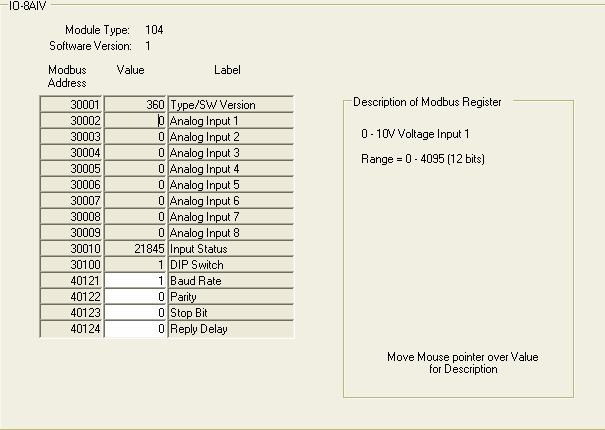

73 73

74 74

75 Configuration: For ex: If you want set baud rate, enter the required value in the register 40121, then press enter in the PC keyboard. Set all the parameters once and then switch off the power supply to the IO Module. Now switch on the Dip switch 10 on the module to make above settings effective, then, user defined communication settings will b effective instead of default communication settings from factory. After power on, the IO Module will have new Communication settings. Please note that at this point of time, IO module may not communicate with PC because you may have different settings at RS232/RS485 converter and also COM port settings in the PC. Testing the IO Module: For ex: If you want to test IO-16DO module. It contains total 16 digital outputs. You can connect IO module with PC as explained above via RS232/RS485 converter. You can force digital output from low to high and check its status at the IO module and also u can observe LED status on the IO Module itself. Note: In field installations, it need to follow good RS485 wiring practice, other wise, it may lead to communication failures. Please refer section 2.4 for more information about RS485 networking If there are problems in communication, it need to test IO modules individually. Connect only one IO module to PC, make sure dipswitch1 is on, dipswitch10 is OFF and then test from IO studio software 75
Data Acquisition Modules/ Distributed IO Modules
 User Manual Data Acquisition Modules/ Distributed IO Modules Future Design Controls, Inc. 7524 West 98 th Place / P.O. Box 1196 Bridgeview, IL 60455 888.751.5444 - Office: 888.307.8014 - Fax 866.342.5332
PROMUX Distributed MODBUS I/O Modules Catalog and Design Guide
 PROMUX Distributed MODBUS I/O Modules Catalog and Design Guide 14/11/2006 V10 P.O.Box 24 Stanfield 3613 SOUTH AFRICA Tel: +27 (031) 7028033 Fax: +27 (031) 7028041 Email: proconel@proconel.com Web: www.proconel.com
PROMUX Distributed MODBUS I/O Modules Catalog and Design Guide
 PROMUX Distributed MODBUS I/O Modules Catalog and Design Guide 12/03/2012 V11.0 P.O.Box 164 Seven Hills 1730 NSW AUSTRALIA Tel: +61 2 96248376 Fax: +61 2 9620 8709 Email: proconel@proconel.com Web: www.proconel.com
NetBiter I/O Extender 4RO 6RTD 8DIO - DAIO User Manual Revision 1.00
 NetBiter I/O Extender 4RO 6RTD 8DIO DAIO User Manual Revision 1.00 IntelliCom Innovation AB Linjegatan 3D SE302 50 Halmstad SWEDEN Phone +46 35 18 21 70 Fax +46 35 18 21 99 email info@intellicom.se www
User Manual Netbiter IO Extender 4RO 6RTD 8DIO DAIO 8AIx 8AIIx
 User Manual Netbiter IO Extender 4RO 6RTD 8DIO DAIO 8AIx 8AIIx Doc. ID. HMSI27228 Rev. 1.20 Connecting Devices TM HALMSTAD CHICAGO KARLSRUHE TOKYO BEIJING MILANO MULHOUSE COVENTRY PUNE COPENHAGEN HMS Industrial
Netbiter IO Extender 4RO 6RTD 8DIO DAIO 8AIV 8AIIS
 USER MANUAL Netbiter IO Extender 4RO 6RTD 8DIO DAIO 8AIV 8AIIS Doc ID: HMSI-27-228 Version: 2.0 HALMSTAD CHICAGO KARLSRUHE TOKYO BEIJING MILANO MULHOUSE COVENTRY PUNE COPENHAGEN RAVENSBURG HMS Industrial
MODBUS MULTIPLEXING I/O SYSTEM CATALOG AND DESIGN GUIDE
 MODMUX MODBUS MULTIPLEXING I/O SYSTEM CATALOG AND DESIGN GUIDE 22/02/2008 V19 P.O.Box 24 Stanfield 3613 SOUTH AFRICA Tel: 27 (031) 7028033 Fax: 27 (031) 7028041 Email: proconel@proconel.com Web: www.proconel.com
Single Channel Loop Detector
 Single Channel Loop Detector Model LD120T Series The LD120T is a series of single channel inductive loop detectors. The use of microprocessor and surface mount technology enables a large number of functions
PL420 PROGRAMMABLE LOGIC CONTROLLER
 PL420 PROGRAMMABLE LOGIC CONTROLLER USER MANUAL 12/01/2007 V02 P.O.Box 24 STANFIELD 3613 SOUTH AFRICA Tel: +27 (031) 7028033 Fax: +27 (031) 7028041 Email: proconel@proconel.com Web: www.proconel.com TABLE
Industrial Modbus I/O Modules
 Industrial Modbus I/O Modules Modbus I/O Modules Introduction & Features Digital Input / Output Modules Analog Input / Output Modules Modbus I/O Modules The Best Choice For Your SCADA Applications Introduction
High Performance Process & Temperature Controllers
 C22 C62 C82 C83 High Performance Process & Temperature Controllers C72 C42 R22 01. Multi Color LCD Display 02. High Accuracy 18 Bit A-D Input and 15 Bit D-A Output 03. 200 msec Sampling Rate 04. True Universal
Instruction Manual MTX-8485C MRX-8485C Four Channel Video Multiplexer with Bi-directional Data
 Instruction Manual MTX-8485C MRX-8485C Four Channel Video Multiplexer with Bi-directional Data Copyright 2005, American Fibertek, Inc. 1027JD Table of Contents Functional Description...3 Installation...3
Excellent low-cost Process & Temperature Controllers
 C22 C62 C82 C83 Excellent low-cost Process & Temperature Controllers C72 C42 R22 01. High Quality LCD Display 02. High Accuracy 18 Bit A-D Input and 15 Bit D-A Output 03. The Fast Sampling Rate in 200
Instruction Manual MTX-8485 MRX-8485 Four Channel Video Multiplexer with Bi-directional Data
 Instruction Manual MTX-8485 MRX-8485 Four Channel Video Multiplexer with Bi-directional Data Copyright 2003, American Fibertek, Inc. 0530JD Table of Contents 2 Functional Description... 4 Installation...
isma-b-w0202 Modbus User Manual GC5 Sp. z o.o. Poland, Warsaw
 isma-b-w0202 isma-b-w0202 Modbus User Manual GC5 Sp. z o.o. Poland, Warsaw www.gc5.com 1. Introduction... 4 2. Safety rules... 4 3. Technical specifications... 5 4. Dimension... 6 5. LED Indication...
PLC-K506 Series FEATURES DESCRIPTION FEATURES
 FEATURES Two High Speed Counters Two Pulse Train Outputs Two Pulse Width Modulation Outputs Inputs 10 Outputs 1 RS232 Port 2 RS485 Ports Supports Modbus RTU Protocol Communicate With Up to 32 Devices DESCRIPTION
ERV-M ELECTRONIC FAN SPEED CONTROLLER. Mounting and operating instructions
 ELECTRONIC FAN SPEED CONTROLLER Mounting and operating instructions Table of contents SAFETY AND PRECAUTIONS 3 PRODUCT DESCRIPTION 4 ARTICLE CODES 4 INTENDED AREA OF USE 4 TECHNICAL DATA 4 STANDARDS 5
UniStream Uni-I/O Modules
 UniStream Uni-I/O Modules Technical Specifications UIS-WCB1 This guide provides specifications for Unitronics Uni-I/O Wide module UIS-WCB1. This module comprises: 10 Digital inputs, 24VDC, sink/source,
AMERITRON RCS-12 AUTOMATIC ANTENNA SWITCH
 AMERITRON RCS-12 AUTOMATIC ANTENNA SWITCH INSTRUCTION MANUAL PLEASE READ THIS MANUAL BEFORE OPERATING THIS EQUIPMENT! 116 Willow Road Starkville, MS 39759 USA 662-323-8211 Version 3B Printed in U.S.A.
Instruction Manual MX-485-S Bi-directional RS485 Data Transceiver
 Instruction Manual MX-485-S Bi-directional RS485 Data Transceiver Copyright 2005, American Fibertek, Inc. 1020JD Table of Contents Functional Description...3 Installation...3 Power Source...3 Power Connection...3
02/11/2015
 Modem communication plug and play solutions GSM Part number 88970119 For remote control of your application Automatic notification of alarms via SMS (GSM Modem) / email or on a PC with M3 ALARM software.
The wireless alternative to expensive cabling...
 The wireless alternative to expensive cabling... ELPRO 105U ISO 9001 Certified New Products... New Solutions The ELPRO 105 range of telemetry modules provide remote monitoring and control by radio or twisted-pair
KNC-PLC-K506 Series FEATURES DESCRIPTION FEATURES
 FEATURES Two High Speed Counters Two Pulse Train Outputs Two Pulse Width Modulation Outputs Inputs 10 Outputs 1 RS232 Port 2 RS485 Ports Supports Modbus RTU Protocol Communicate with up to 32 devices DESCRIPTION
MV110-8AS. Analog input module 8 channel. User guide
 MV110-8AS Analog input module 8 channel User guide MV110-8AS_2016.12_0226_EN All rights reserved Subject to technical changes and misprints Contents 1 Description... 2 1.1 Function... 2 1.2 RS485 network...
905U Wireless. New Products... New Solutions. The wireless alternative to expensive cabling... Simple but Reliable. Easy to Use
 Wireless New Products... New Solutions The range of telemetry modules provide remote monitoring and control by radio or twisted-pair wire, over short or long distances. Transducer signals connected at
PM-311x Quick Start Ver PM-311x introduction 1.1. Caution & Warning 1.2. Product Warranty & Customer Support
 PM-311x Quick Start Ver. 1.1 1. PM-311x introduction ICP DAS brings the most powerful, cost-effective, advanced Smart Power Meters PM-3000 series that gives you access to real-time electric usage for single-phase
Uni-Mux XQL Multi-Channel Data Acquisition Module
 Uni-Mux XQL Multi-Channel Data Acquisition Module Uni-Mux XQL Multi-Channel Data Acquisition Module * 8 channel differential inputs. * 16 channel single ended inputs. * User programmable via P.C. software.
sw rev. 55B DEVICE FOR THE PERMANENT CONTROL OF INSULATION ON THE SUPPLY LINES IN MEDICAL PRACTICE PLACES INSTALLATIONS
 INSTRUCTIONS MANUAL IM831-U v0.92 HRI-R40W sw rev. 55B DEVICE FOR THE PERMANENT CONTROL OF INSULATION ON THE SUPPLY LINES IN MEDICAL PRACTICE PLACES INSTALLATIONS INDEX: GENERAL TYPES ACESSORIES AND OPTIONS
VFSC9 ELECTRONIC SPEED CONTROLLER. Mounting and operating instructions
 ELECTRONIC SPEED CONTROLLER Mounting and operating instructions Table of contents SAFETY AND PRECAUTIONS 3 PRODUCT DESCRIPTION 4 ARTICLE CODES 4 INTENDED AREA OF USE 4 TECHNICAL DATA 4 STANDARDS 5 WIRING
MU110-16R(K) Digital output module 16 channel. User guide
 Digital output module 16 channel. User guide") MU110-16R(K) Digital output module 16 channel User guide MU110-16R(K)_2016.12_0220_EN All rights reserved Subject to technical changes and misprints akytec GmbH Vahrenwalder Str. 269 A 30179 Hannover Germany
MU110-16R(K) Digital output module 16 channel User guide MU110-16R(K)_2016.12_0220_EN All rights reserved Subject to technical changes and misprints akytec GmbH Vahrenwalder Str. 269 A 30179 Hannover Germany
Model FLSC-C3-XX. DC Powered Microprocessor Controlled Transmitter
 Model FLSC-C3-XX DC Powered Microprocessor Controlled Transmitter CONTENTS. Introduction----------------------------------------------------------------- 2 2. Specifications ---------------------------------------------------------------
CCE Image may differ from the actual product By Martin Labbé, eng., Jasmin Goupil & Louis Perreault
 CCE-32 1.09 Image may differ from the actual product By Martin Labbé, eng., Jasmin Goupil & Louis Perreault Index 1. General description... 5 2. Applications... 5 3. Installation... 5 4. Connections...
Instruction Manual TABLE OF CONTENTS 1 PRINCIPLE OF OPERATION Limitations INSTALLATION Mains connection...
 instrumentación para fluidos CI- pulse / ma Converter Instruction Manual TABLE OF CONTENTS PRINCIPLE OF OPERATION.... Limitations.... INSTALLATION.... Mains connection........ Input connection........
02/11/2015
 Modem communication plug and play solutions GSM Part number 88970119 For remote control of your application Automatic notification of alarms via SMS (GSM Modem) / email or on a PC with M3 ALARM software.
Instruction Manual MX-480 Bi-directional Multi-Protocol Data
 Instruction Manual MX-480 Bi-directional Multi-Protocol Data Copyright 2007, American Fibertek, Inc. 1210JD Table of Contents Functional Description...3 Installation...3 Power Source...3 Power Connection...4
The wireless alternative to expensive cabling...
 The wireless alternative to expensive cabling... ELPRO 905U Wireless Solutions for Process Applications New Products... New Solutions The ELPRO 905U range of telemetry modules provide remote monitoring
ADAM 4000/4100 Series
 ADAM 4000/4100 Series Common Dimensions Communication RS-485 (2-wire) to host Speeds: 1200, 2400, 4800, 9600, 19200, 38400, 57600, 115200 bps (ADAM-4080, ADAM-4080D only support up to 38400 bps) Max. communication
Z-10-D-IN. RS485 Modbus Module 10 Digital Inputs
 S SENECA Z-PC Line EN Installation Manual Contents: - General specifications - Technical specifications - Installation rules - Electrical connections - Modbus connection rules - DIP-switches settings -
Analog Module D1-15P User Manual
 D1-15P Manual Analog Module D1-15P User Manual Sielco Elettronica Srl Edison Street 209 20019 Settimo Milanese (MI) - Italy http://www.sielcoelettronica.com info @ sielcoelettronica.com Tel 02 48916252
Modbus communication module for TCX2: AEX-MOD
 Modbus communication module for TCX2: Communication Specification TCX2 is factory installed in TCX2 series controllers with -MOD suffix, and is also available separately upon request for customer installation
The wireless alternative to expensive cabling...
 The wireless alternative to expensive cabling... ELPRO 105U Wireless Solutions for Process Applications New Products... New Solutions The ELPRO 105U range of wireless I/O provides a low cost alternative
Series 500. Owner s Manual. Analog Transmitters by Data Industrial. Data Industrial. Data Industrial 2/95 PN 72806
 Series 500 Analog Transmitters by Data Industrial Data Industrial Owner s Manual Data Industrial 2/95 PN 72806 Table of Contents Introduction... 1 4-20 ma Loop Supply Requirements... 2 Installation...
AMU-214 Auxiliary Monitor Unit Operations Manual
 AMU-214 Auxiliary Monitor Unit THIS MANUAL CONTAINS TECHNICAL INFORMATION FOR THE AMU-214 SERIES ITS CABINET AUXILIARY MONITOR UNIT. REVISION: SEPTEMBER 2008 pn 888-0214-001 THE AMU-214 SERIES AUXILIARY
PROCESS & TEMPERATURE CONTROLLERS
 PROCESS & TEMPERATURE CONTROLLERS NOVA PD54 Series Thermocouple, RTD, & Process Inputs High Accuracy Auto-Tuning PID Heating & Cooling Models Universal Power Supply 1-24 VAC Up to 3 Relays & 2 Analog Outputs
DISCRETE INPUT MODULE, 16 points
 INSTRUCTION MANUAL DISCRETE INPUT MODULE, points (Modbus) RM-DA MODEL RM-DA BEFORE USE... Thank you for choosing M-System. Before use, please check contents of the package you received as outlined below.
K-Factor Scaler F5140 and Programming Kit F5141 Installation & Operating Instructions
 F5140 and Programming Kit F5141 8635 Washington Avenue Racine, WI 53406 USA Tel: 800-433-5263 or 262-639-6770 Fax: 800-245-3569 or 262-639-2267 E-Mail: flo-techsales@racinefed.com www.flo-tech.com TABLE
815PT Smart Pressure Transmitter
 815PT Smart Pressure Transmitter General Instructions These instructions provide information for installation, process connection, electrical connection, configuration, operation and maintenance of the
MU110-8R(K) Digital output module 8 channel. User guide
 Digital output module 8 channel. User guide") MU110-8R(K) Digital output module 8 channel User guide MU110-8R(K)_2019.01_0296_EN All rights reserved Subject to technical changes and misprints akytec GmbH Vahrenwalder Str. 269 A 30179 Hannover Germany
MU110-8R(K) Digital output module 8 channel User guide MU110-8R(K)_2019.01_0296_EN All rights reserved Subject to technical changes and misprints akytec GmbH Vahrenwalder Str. 269 A 30179 Hannover Germany
Ocean Controls KT-5221 Modbus IO Module
 Ocean Controls Modbus IO Module 8 Relay Outputs 4 Opto-Isolated Inputs 2 Analog Inputs (10 bit) 1 PWM Output (10 bit) 4 Input Counters Connections via Pluggable Screw Terminals 0-5V or 0-20mA Analog Inputs,
MBC Bipolar Microstep Driver. User s Guide E. Landon Drive Anaheim, CA
 MBC10641 Bipolar Microstep Driver User s Guide A N A H E I M A U T O M A T I O N 4985 E. Landon Drive Anaheim, CA 92807 e-mail: info@anaheimautomation.com (714) 992-6990 fax: (714) 992-0471 website: www.anaheimautomation.com
Quick Start Guide. ELPRO 905U-L-T Wireless I/O Transmitter Unit. man_905u-l-t_quickstart_v1-7.doc
 Quick Start Guide ELPRO 905U-L-T Wireless I/O Transmitter Unit man_905u-l-t_quickstart_v1-7.doc ELPRO 905U-L-T Wireless I/O Transmitter Unit Quick Start Guide About this document This document is the ELPRO
Programmable K-Factor Scaler B and Programming Software Kit B
 Programmable K-Factor Scaler B220-885 and Programming Software Kit B220-900 INSTALLATION & INSTRUCTION MANUAL 8635 Washington Avenue Racine, Wisconsin 53406 Toll Free: 800.235.1638 Phone: 262.639.6770
Custom "Compact" range with display CD20 Custom Part number
 Custom "Compact" range with display CD20 Custom Part number 88974051 "Modular" versions designed for Custom application-specific functions (Custom functions) LCD with 4 lines of 18 characters and configurable
The wireless alternative to expensive cabling...
 The wireless alternative to expensive cabling... ELPRO 905U Wireless Solutions for Process Applications New Products... New Solutions The ELPRO 905U range of wireless I/O provides a low cost alternative
Instruction Manual MT-945SL Four Channel Video Transmitter With Two Bi-Directional Data Channels
 Instruction Manual MT-945SL Four Channel Video Transmitter With Two Bi-Directional Data Channels Copyright 2006, American Fibertek, Inc. 0307JD Table of Contents Functional Description... 3 Installation...
USER MANUAL MODEL Parallel to Serial/ Serial to Parallel Interface Converter
 USER MANUAL MODEL 2029 Parallel to Serial/ Serial to Parallel Interface Converter C E R T I F I E D An ISO-9001 Certified Company Part #07M2029-B, Rev. C Doc. #102011UB Revised 6/16/09 SALES OFFICE (301)
MDC VAC Input Brushless Controller. User s Guide. 910 East Orangefair Lane, Anaheim, CA
 MDC200-048051 110VAC Input Brushless Controller User s Guide A N A H E I M A U T O M A T I O N 910 East Orangefair Lane, Anaheim, CA 92801 e-mail: info@anaheimautomation.com (714) 992-6990 fax: (714) 992-0471
Technical Manual TRANSDUCER AMPLIFIER TYPE DR7AC. Doc. Ref CD2402K
 RDP CUSTOMER DOCUMENT Technical Manual TRANSDUCER AMPLIFIER TYPE DR7AC Doc. Ref CD2402K BS EN ISO 9001 Certificate No. FM13141 Affirmed by Declaration of Conformity USA & Canada RDP Electrosense Inc. 2216
MLA High Performance Microstepping Driver. User s Guide E. Landon Drive Anaheim, CA
 MLA10641 High Performance Microstepping Driver User s Guide A N A H E I M A U T O M A T I O N 4985 E. Landon Drive Anaheim, CA 92807 e-mail: info@anaheimautomation.com (714) 992-6990 fax: (714) 992-0471
TECO F510 Inverter. Quick Start Guide. Step 1. Supply & Motor connection
 Quick Start Guide TECO F510 Inverter This guide is to assist you in installing and running the inverter and verify that it is functioning correctly for it s main and basic features. For detailed information
OptiLogic Series. Input/Output Modules. Optimal Automation for Industry. Optimation, Inc. (256)
") Input/Output Modules Optimal Automation for Industry Optimation, Inc. ()-00 WARNING Thank you for purchasing industrial control products from Optimation, Inc. We want your new system to operate safely.
Input/Output Modules Optimal Automation for Industry Optimation, Inc. ()-00 WARNING Thank you for purchasing industrial control products from Optimation, Inc. We want your new system to operate safely.
269 Troubleshooting Guide 11/4/98 1
 269 Troubleshooting Guide 11/4/98 1 Table of Contents Phase currents 3 Communications. 6 RTDs.. 9 Ground Fault Currents... 13 Output Relays. 15 Analog Output 17 Switch Inputs...18 11/4/98 2 Phase Currents
VersaMax Mixed Discrete / High-Speed Counter Module
 Product Description The VersaMax Mixed Discrete High-Speed Counter (HSC) module,, has twenty 24VDC positive-logic type inputs and twelve positive-logic 24VDC 0.5Amp outputs. In its default configuration,
SMARTALPHA RF TRANSCEIVER
 SMARTALPHA RF TRANSCEIVER Intelligent RF Modem Module RF Data Rates to 19200bps Up to 300 metres Range Programmable to 433, 868, or 915MHz Selectable Narrowband RF Channels Crystal Controlled RF Design
UniStream Built-in. Technical Specifications US7-B5-RA28, US7-B10-RA28 US7-B5-TA30, US7-B10-TA30
 UniStream Built-in Technical Specifications US5-B5-RA28, US5-B10-RA28 US5-B5-TA30, US5-B10-TA30 US7-B5-RA28, US7-B10-RA28 US7-B5-TA30, US7-B10-TA30 Unitronics UniStream Built-in series are PLC+HMI All-in-One
SRC-110 Series Zone Controllers with Modbus RTU
 Product sheet CT2.142 Type SRC-110-MOD SRC-110 Series Zone Controllers with Modbus RTU The SRC-110 series controllers have been designed for zone heating and cooling control. The controllers have 3 analogue
BCV-1203 Barcode Verification System Users Guide Version 1.2
 BCV-1203 Barcode Verification System Users Guide Version 1.2 6 Clock Tower Place Suite 100 Maynard, MA 01754 USA Tel: (866) 837-1931 Tel: (978) 461-1140 FAX: (978) 461-1146 http://www.diamondt.com/ Liability
Quick Start Guide. ELPRO 905U-L-T Wireless I/O Transmitter Unit. man_905u-l-t_quickstart_v1.9.doc
 Quick Start Guide ELPRO 905U-L-T Wireless I/O Transmitter Unit man_905u-l-t_quickstart_v1.9.doc About this document This document is the and contains the following sections: Section Basic steps for using
02/11/2015
 Smart range with Removable Terminal blocks XD26RBT Smart Part number 88974561 Designed for industrial, commercial, medical and paramedical machines Faster maintenance process which improves the machine
af i Instruction Manual MR-944C Four Channel Video Receiver With One Bi-Directional Multi-Protocol Data Channel american fibertek 11/30/2012 JPK
 af i american fibertek Instruction Manual MR-944C Four Channel Video Receiver With One Bi-Directional Multi-Protocol Data Channel 11/30/2012 JPK Table of Contents Functional Description... 3 Installation...
USER MANUAL Z-8TC. Via Germania, Z.I. CAMIN PADOVA ITALY. Via Svizzera, Z.I. CAMIN PADOVA ITALY
 USER MANUAL Z-8TC SENECA s.r.l. Via Germania, 34 35127 Z.I. CAMIN PADOVA ITALY Via Svizzera, 17 35127 Z.I. CAMIN PADOVA ITALY Tel. +39.049.8705355 8705359 Fax. +39.049.8706287 Web site: www.seneca.it Technical
VT1586A Rack Mount Terminal Panel Installation and User s Manual
 VT1586A Rack Mount Terminal Panel Installation and User s Manual Manual Part Number: 82-0095-000 Rev. June 16, 2003 Printed in U.S.A. Certification VXI Technology, Inc. certifies that this product met
This Errata Sheet contains corrections or changes made after the publication of this manual.
 Errata Sheet This Errata Sheet contains corrections or changes made after the publication of this manual. Product Family: DL4 Date: September 12, 218 Manual Number D4-ANLG-M Revision and Date th Ed., Rev.
There are many important factors when trying to achieve good, reliable communications between 2 devices.
 APPLICATION NOTE THIS INFORMATION PROVIDED BY AUTOMATIONDIRECT.COM TECHNICAL SUPPORT These documents are provided by our technical support department to assist others. We do not guarantee that the data
Fuzzy Temperature Controllers E5AF
 Fuzzy Temperature Controllers 1/4 DIN Controller Combines Fuzzy and PID Control For Fast Response to Process Disturbances Advanced PID control provides optimal response during start-up and steadystate
"Modular" versions designed for application-specific functions LCD with 4 lines of 18 characters and configurable backlighting
 Smart "Compact" range with display CD12 Smart Part number 88974043 "Modular" versions designed for application-specific functions LCD with 4 lines of 18 characters and configurable backlighting Type Input
bhi bhi DSP Noise Cancelling Products DSP Noise Cancelling Products NEDSP1061-PCB bhi ltd PO Box 318 Burgess Hill West Sussex RH15 9NR
 DSP Noise Cancelling Products bhi bhi ltd PO Box 318 Burgess Hill West Sussex RH15 9NR tel: +44 (0)845 217 9926 fax: +44 (0)845 217 9936 sales@bhi-ltd.com www.bhi-ltd.com DSP Noise Cancelling Products
WIRELESS MODBUS GATEWAY WGW410
 WIRELESS MODBUS GATEWAY WGW410 The Tekon Wireless Modbus Gateway WGW410 is specifically designed to meet the most rigorous requirements of operation in the industrial process environments. Due to their
LAUREL ELECTRONICS, INC.
 LAUREL ELECTRONICS, INC. Laureate True RMS AC Voltage & Current Meter with 1 Cycle Update at 50/60 Hz Features True AC or AC plus DC RMS measurement with crest factor of 3.0 at FS Fast response: reading
INSTRUCTIONS MANUAL DEVICE FOR THE PERMANENT CONTROL OF INSULATION ON THE SUPPLY LINES IN MEDICAL PRACTICE PLACES INSTALLATIONS HRI-R40W
 Page 2 / 16 INDEX: GENERAL TYPES ACESSORIES AND OPTIONS INSTALLATION WIRING DIAGRAMS CONNECTING TERMINALS DIAGRAMS WIRING DIAGRAM DESCRIPTION WORKING DESCRIPTION AND KEYBOARD WORKING DESCRIPTION AND PROGRAMMING
OPERATION & SERVICE MANUAL FOR FC 110 AC POWER SOURCE
 OPERATION & SERVICE MANUAL FOR FC 100 SERIES AC POWER SOURCE FC 110 AC POWER SOURCE VERSION 1.3, April 2001. copyright reserved. DWG No. FC00001 TABLE OF CONTENTS CHAPTER 1 INTRODUCTION... 1 1.1 GENERAL...
Rev NGM EVO USER GUIDE
 www.promax.it The information contained in this document are for informational purposes only and are subject to change without notice and should not be interpreted by any commitment by Promax srl. Promax
UNICOM 2500 UNICOM Installation Operation Programming. Universal Communication Converter
 User Manual UNICOM 2500 Installation Operation Programming Universal Communication Converter UNICOM 2500 Electro Industries/GaugeTech 1800 Shames Drive Westbury, New York 11590 Tel 516.334.0870 Fax 516.338.4741
Digital Lighting Systems, Inc.
 PD408-AN0-277 ANALOG 0-0 V 0-0V analog control 4 Channel x 2250 W Dimmer & Switch Packs 220/240/277 Volts operation PD408-AN0-277 4 circuit Analog -0V 4 x 8 A. Dimmer pack Serial Number Digital Lighting
User's Manual: Series 450T AC Current Input (External Sensor), AC-Powered Transmitters
, AC-Powered Transmitters") User's Manual: Series 450T AC Current Input (External Sensor), AC-Powered Transmitters Table of Contents Page Introduction 1 Description 1 Specifications 2 Installation 3 Calibration 4 General Maintenance
User's Manual: Series 450T AC Current Input (External Sensor), AC-Powered Transmitters Table of Contents Page Introduction 1 Description 1 Specifications 2 Installation 3 Calibration 4 General Maintenance
MK110-8D.4R. Digital I/O-Module 12 channel 8 DI, 4 DO. User guide
 MK110-8D.4R Digital I/O-Module 12 channel 8 DI, 4 DO User guide MK110-8D4R_2016.12_0219_EN All rights reserved Subject to technical changes and misprints akytec GmbH Vahrenwalder Str. 269 A 30179 Hannover
02/11/2015
 "Compact" range with display CD12 Part number 88970041 Green LCD with 4 lines of 18 characters and configurable backlighting More cost effective solution Industrial temperature range (-20 C +55 C) Analogue
SC-FI Series Frequency to Current Signal Conditioner
 SC-FI Series Frequency to Current Signal Conditioner 99829 08/27/01 INDEX DESCRIPTION... 1 SPECIFICATIONS... 1 TYPICAL WIRING HOOKUP... 1 INPUT & OUTPUT SETTINGS... 2 "L" OPTION SPECIFICATIONS... 3 "L"
Selection guide. Communication accessories. Communication accessory selection guide. Characteristics
 Communication accessories Selection guide There are 2 types of Sepam communication accessories: b communication interfaces, which are essential for connecting Sepam to the communication network b converters
WEL-200 O P E R A T I N G I N S T R U C T I O N S W I R E L E S S E D G E L I N K
 O P E R A T I N G I N S T R U C T I O N S WEL-200 TM W I R E L E S S E D G E L I N K 4564 Johnston Parkway, Cleveland, Ohio 44128 P. 800 426 9912 F. 216 518 9884 Sales Inquiries: salessupport@emxinc.com
K-FACTOR SCALER B & B
 K-FACTOR SCALER B220-880 & B220-881 INSTALLATION & INSTRUCTION MANUAL 8635 Washington Ave. Racine, Wisconsin 53406 Technical Toll-Free: 877.722.4631 Sales Toll-Free: 800.235.1638 Phone: 262.639.6770 Fax:
1M122A Transformer Parallel Control System
 Technical Bulletin 1M122A Transformer Parallel Control System Features CONTROL SYSTEM FEATURES Simple system wiring Scaleable up to 4 transformers Flexible control configuration Set transformers in any
Quick Start Guide. ELPRO 105U-L-T Wireless I/O Transmitter Unit. man_105u-l-t_quickstart_v1-8.doc
 Quick Start Guide ELPRO 105U-L-T Wireless I/O Transmitter Unit man_105u-l-t_quickstart_v1-8.doc ELPRO 105U-L-T Wireless I/O Transmitter Unit Quick Start Guide About this document This document is the ELPRO
em4 local - Robust Specific characteristics Part number
 em4 em4 local em4 local Very compact and easy to program nanoplc Save time in designing your application using the most intuitive graphical function block language of the market Measure accurately your
PULSE INPUT MODULE PI232/PI272 USER S MANUAL
 UM-TS02 -E021 PROGRAMMABLE CONTROLLER PROSEC T2-series PULSE INPUT MODULE PI232/PI272 USER S MANUAL TOSHIBA CORPORATION Important Information Misuse of this equipment can result in property damage or human
GCX. Guitar Audio Switcher OWNER S MANUAL
 GCX Guitar Audio Switcher OWNER S MANUAL Please visit our web site at: www.voodoolab.com Copyright 1998 by Digital Music Corporation. This publication is protected by copyright and all rights are reserved.
Jaguar Motor Controller (Stellaris Brushed DC Motor Control Module with CAN)
") Jaguar Motor Controller (Stellaris Brushed DC Motor Control Module with CAN) 217-3367 Ordering Information Product Number Description 217-3367 Stellaris Brushed DC Motor Control Module with CAN (217-3367)
Jaguar Motor Controller (Stellaris Brushed DC Motor Control Module with CAN) 217-3367 Ordering Information Product Number Description 217-3367 Stellaris Brushed DC Motor Control Module with CAN (217-3367)
The MP SERIES CONTROLLER. User s Manual. ISE, Inc.
 The MP SERIES CONTROLLER User s Manual ISE, Inc. 10100 Royalton Rd. Cleveland, OH 44133 USA Tel: (440) 237-3200 Fax: (440) 237-1744 http://variac.com Form No, 003-1622 Rev G 02/25/2009 Form No. 003-1622
UniStream 5" Technical Specifications US5-B5-RA28, US5-B10-RA28
 UniStream 5" Technical Specifications US5-B5-RA28, US5-B10-RA28 Unitronics UniStream 5" are PLC+HMI All-in-One programmable controllers that comprise built-in HMI and built-in I/Os. The series is available
815LT Submersible Smart Level Transmitter
 These instructions provide information for installation, process connection, electrical connection, configuration, operation and maintenance of the 815LT Submersible Smart Level Transmitter. The 815LT